EP3425471B1 - Procédé de transport sans perturbations de rayonnages de chargement dans des usines à fonctionnement de roulage partiellement autonome - Google Patents
Procédé de transport sans perturbations de rayonnages de chargement dans des usines à fonctionnement de roulage partiellement autonome Download PDFInfo
- Publication number
- EP3425471B1 EP3425471B1 EP18191141.3A EP18191141A EP3425471B1 EP 3425471 B1 EP3425471 B1 EP 3425471B1 EP 18191141 A EP18191141 A EP 18191141A EP 3425471 B1 EP3425471 B1 EP 3425471B1
- Authority
- EP
- European Patent Office
- Prior art keywords
- transport vehicle
- load
- load shelf
- shelf
- route
- Prior art date
- Legal status (The legal status is an assumption and is not a legal conclusion. Google has not performed a legal analysis and makes no representation as to the accuracy of the status listed.)
- Active
Links
Images


Classifications
-
- G—PHYSICS
- G05—CONTROLLING; REGULATING
- G05D—SYSTEMS FOR CONTROLLING OR REGULATING NON-ELECTRIC VARIABLES
- G05D1/00—Control of position, course, altitude or attitude of land, water, air or space vehicles, e.g. using automatic pilots
- G05D1/02—Control of position or course in two dimensions
- G05D1/021—Control of position or course in two dimensions specially adapted to land vehicles
- G05D1/0287—Control of position or course in two dimensions specially adapted to land vehicles involving a plurality of land vehicles, e.g. fleet or convoy travelling
- G05D1/0291—Fleet control
- G05D1/0297—Fleet control by controlling means in a control room
-
- B—PERFORMING OPERATIONS; TRANSPORTING
- B60—VEHICLES IN GENERAL
- B60P—VEHICLES ADAPTED FOR LOAD TRANSPORTATION OR TO TRANSPORT, TO CARRY, OR TO COMPRISE SPECIAL LOADS OR OBJECTS
- B60P1/00—Vehicles predominantly for transporting loads and modified to facilitate loading, consolidating the load, or unloading
- B60P1/02—Vehicles predominantly for transporting loads and modified to facilitate loading, consolidating the load, or unloading with parallel up-and-down movement of load supporting or containing element
-
- B—PERFORMING OPERATIONS; TRANSPORTING
- B60—VEHICLES IN GENERAL
- B60P—VEHICLES ADAPTED FOR LOAD TRANSPORTATION OR TO TRANSPORT, TO CARRY, OR TO COMPRISE SPECIAL LOADS OR OBJECTS
- B60P1/00—Vehicles predominantly for transporting loads and modified to facilitate loading, consolidating the load, or unloading
- B60P1/64—Vehicles predominantly for transporting loads and modified to facilitate loading, consolidating the load, or unloading the load supporting or containing element being readily removable
- B60P1/6409—Vehicles predominantly for transporting loads and modified to facilitate loading, consolidating the load, or unloading the load supporting or containing element being readily removable details, accessories, auxiliary devices
-
- B—PERFORMING OPERATIONS; TRANSPORTING
- B66—HOISTING; LIFTING; HAULING
- B66F—HOISTING, LIFTING, HAULING OR PUSHING, NOT OTHERWISE PROVIDED FOR, e.g. DEVICES WHICH APPLY A LIFTING OR PUSHING FORCE DIRECTLY TO THE SURFACE OF A LOAD
- B66F9/00—Devices for lifting or lowering bulky or heavy goods for loading or unloading purposes
- B66F9/06—Devices for lifting or lowering bulky or heavy goods for loading or unloading purposes movable, with their loads, on wheels or the like, e.g. fork-lift trucks
- B66F9/063—Automatically guided
-
- B—PERFORMING OPERATIONS; TRANSPORTING
- B66—HOISTING; LIFTING; HAULING
- B66F—HOISTING, LIFTING, HAULING OR PUSHING, NOT OTHERWISE PROVIDED FOR, e.g. DEVICES WHICH APPLY A LIFTING OR PUSHING FORCE DIRECTLY TO THE SURFACE OF A LOAD
- B66F9/00—Devices for lifting or lowering bulky or heavy goods for loading or unloading purposes
- B66F9/06—Devices for lifting or lowering bulky or heavy goods for loading or unloading purposes movable, with their loads, on wheels or the like, e.g. fork-lift trucks
- B66F9/075—Constructional features or details
- B66F9/0755—Position control; Position detectors
-
- B—PERFORMING OPERATIONS; TRANSPORTING
- B66—HOISTING; LIFTING; HAULING
- B66F—HOISTING, LIFTING, HAULING OR PUSHING, NOT OTHERWISE PROVIDED FOR, e.g. DEVICES WHICH APPLY A LIFTING OR PUSHING FORCE DIRECTLY TO THE SURFACE OF A LOAD
- B66F9/00—Devices for lifting or lowering bulky or heavy goods for loading or unloading purposes
- B66F9/06—Devices for lifting or lowering bulky or heavy goods for loading or unloading purposes movable, with their loads, on wheels or the like, e.g. fork-lift trucks
- B66F9/075—Constructional features or details
- B66F9/07586—Suspension or mounting of wheels on chassis
-
- G—PHYSICS
- G05—CONTROLLING; REGULATING
- G05D—SYSTEMS FOR CONTROLLING OR REGULATING NON-ELECTRIC VARIABLES
- G05D1/00—Control of position, course, altitude or attitude of land, water, air or space vehicles, e.g. using automatic pilots
- G05D1/02—Control of position or course in two dimensions
- G05D1/021—Control of position or course in two dimensions specially adapted to land vehicles
- G05D1/0231—Control of position or course in two dimensions specially adapted to land vehicles using optical position detecting means
- G05D1/0238—Control of position or course in two dimensions specially adapted to land vehicles using optical position detecting means using obstacle or wall sensors
- G05D1/024—Control of position or course in two dimensions specially adapted to land vehicles using optical position detecting means using obstacle or wall sensors in combination with a laser
Definitions
- the present invention relates to a method for the trouble-free transport of load racks in factory halls with partially autonomous driving operation.
- a container can be a packaged or unpacked piece of goods or a combination of goods such as a box, a carton or a crate with bulk goods or several individual goods such as drinks bottles or dairy products.
- AGVs automated guided vehicles
- AGVs automated guided vehicles
- Conventional automated guided vehicles which are used to move materials in factories and warehouses, for example, have minimal point-to-point motion control.
- Most such systems use AGVs that follow a fixed guide track. This is generally a high-frequency transmitting antenna wire that is recessed into the factory floor, a reflective strip painted on the floor, or a reflective tape.
- guide tracks are obviously very vulnerable and unreliable.
- All of these motion controls limit the freedom of movement of individual AGVs by forcing them to follow a physically defined path.
- the control scheme implements a "static" collision avoidance scheme for AGV systems. Essentially, a computer program is used to examine the environment of an AGV to determine only those paths that are passable for AGVs. Another allocation program uses this to extract the necessary data to move AGVs from one point to another point in the system without two AGVs traveling the same path at the same time.
- the DE 689 28 565 T2 According to the information in claim 1, a method for guiding several automatically guided vehicles (AGV) along a network of interconnected paths that begin, end, and contain nodes.
- AGV automatically guided vehicles
- This method involves creating a record of a route to be followed by the specific AGV in the form of path segments starting at a node and ending at the next node.
- An indication of the position of a specific AGV is also determined.
- each node an indication is derived as to whether it is free or occupied.
- a list of nodes is generated that includes the node currently visited by the particular AGV, at least some nodes along the recorded route that the particular AGV will visit. This includes checking that each node in the list is free before adding it to the list, and marking each node in the list as busy after adding it to the list. Further, the list of nodes is transmitted to the particular AGV and causing it to move forward along the recorded route through the nodes.
- the publication US 2008/001372 A1 discloses a method for operating a transport vehicle for the trouble-free transport of load racks in factory halls with partially autonomous driving, wherein a control center ensures that a load rack with a transport item located on it is transported to a destination, wherein the control center determines which transport vehicle is able to complete the required order most quickly due to its current location and its current order situation, and the transport vehicle then receives an order from the control center to search for the load rack in a larger area of a storage area, to pick up the load rack and to transport the load rack with the goods on it to the destination.
- the transport vehicle selected by the control center receives route instructions regarding the route to be taken and the speed to be driven in each section of the route in order to reach the destination within a certain time frame.
- the transport vehicle uses a sensor to detect the load rack to be picked up, selects a suitable starting position for picking up the load rack, drives underneath it and lifts it up for removal.
- the invention is therefore based on the object of creating a method for operating a transport vehicle with which the reliable transport of load racks can be carried out without disruption even on uneven ground and on slight inclines.
- the Fig.1 shows an arrangement of load racks to be transported.
- the Fig.2 shows an approach of a transport vehicle 9 to load racks 1.
- FIG.2 In the left area of the Fig.2 Two load racks 1 standing one behind the other with their shelf posts 7 and the goods to be transported 2 are shown.
- a transport vehicle 9 approaches these two load racks 1 by means of two drive wheels 5, of which only one can be seen in the side view, and a front and a rear support wheel 8.
- the transport vehicle 9 has a support plate 4 that is adjustable in height.
- each of these Vehicles have at least one laser scanner 3 and one light field sensor 6 on the front.
- mini lenses which collect optical information in the form of hundreds of mini lenses based on the light field principle, which can then later be compiled into images with a desired resolution and/or a desired viewing angle.
- mini lenses are 3D capable, inexpensive to manufacture and follow the principle of an insect eye.
- Fig.3 shows a representation of shelf posts as an orientation aid.
- Each shelf post 7 can have a marking in the form of a barcode or data matrix code on each of its four sides, which identifies it as part of a specific storage shelf and makes it identifiable from all sides for a transport vehicle 9, primarily by means of its laser scanner.
- the Fig.4 shows an orientation situation of a transport vehicle 9 with real obstacles.
- this involves a normal load rack 1, which can be identified as previously described, and on the other hand, a person 10 who does not actually belong in this environment.
- a person 10 who represents an unusual obstacle is detected by a transport vehicle 9 using a light field sensor.
- the Fig.5 shows a side view of a loaded transport vehicle 9. Its drive wheels and the support wheels touch the floor and the load shelf 1 rests on the carrier plate of the transport vehicle
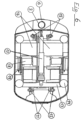
- the Fig.6 shows a top view of the kinematics of the transport vehicle 9.
- an adjusting element 17 In a central position in the longitudinal direction, an adjusting element 17 can be seen which, when extended in the longitudinal direction, causes the four circular centering elements 14 shown to be raised via lifting elements that are not visible in this illustration.
- the centering elements 14 fit into corresponding recesses in the carrier plate.
- the rear support plate suspension 12 and the front support plate suspension 15 can be seen as part of the lever elements mentioned.
- the adjusting element 17 rests on a wishbone 13 which is connected to the two rear lifting rod levers 11 via lifting elements that are not visible here.
- both servomotors for the two drive wheels can be seen, although only the left one is marked 18.
- the spring elements leading to both drive wheels ensure that the drive wheels maintain secure contact with the ground even on uneven ground via deflection levers (not visible here).
- only the spring element on the left in the direction of travel is marked 19.
- 16 represents a left-hand and a right-hand space for energy storage. These can be electric batteries or energy storage for other liquid or gaseous forms of energy.
- a laser scanner 3 and a light field sensor 6 are mounted on the front of the transport vehicle 9.
- both types of sensors can also be additionally mounted on the two sides and/or on the rear of a transport vehicle.
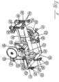
- the Fig.7 shows a detailed representation of the kinematics of the transport vehicle.
- This illustration shows the transport vehicle without the enclosing housing. Connections to the Housing is indicated at the appropriate point.
- the kinematics of the drive wheels are explained.
- In the foreground is the Fig. 2 known, left-hand drive wheel 5 and the associated rotation axis 32 can be seen, which is attached to the unspecified housing of the transport vehicle.
- the axle bearing 34 for the left-hand drive wheel 5 with its servo motor 18 above it, which serves as a drive for the drive wheel 5, are connected to form a functional unit by means of an angle plate, unspecified and only visible from the rear.
- a toothed belt runs in this angle plate, over which the servo motor 18 drives the rotation axis of the left-hand drive wheel 5.
- the corresponding servo motor 22 for the right-hand drive can be seen.
- the corresponding angle plate can be seen from the rear in the illustration shown.
- the corresponding toothed belt 20 running in this angle plate is marked.
- the entire functional unit, consisting of the drive wheel 5 with the axle bearing 34, the servo motor 18 and the angle plate with its toothed belt, can be pivoted about the above-mentioned axis of rotation 32 via an angle lever 31.
- the angle lever 31 is connected via a joint 30 to a U-shaped wishbone 13 that runs across almost the entire width of the transport vehicle, to the other end of which the right-hand drive wheel is attached accordingly.
- a spring element 19 is also mounted on the joint 30, the other bearing point of which is attached to the housing of the transport vehicle.
- this articulation point is shown as a block-shaped, barely recognizable bearing above the drive wheel 5.
- this point is designated as the articulation point 21 of the corresponding right spring element.
- the spring element 19 serves the purpose of pressing the drive wheel 5 onto the ground surface via the angle lever 31 and thus improving the ground contact of the drive wheel 5. The same applies to the opposite right drive wheel.
- the front lifting rods 40 and the rear lifting rods 26 serve this purpose in direct contact.
- the lifting rods 40 and 26 are raised and lowered by means of an actuating element 17, which in turn applies the necessary forces by means of a threaded spindle via a retractable and extendable cylinder via a joint head 39 and a hinged lifting rotary lever 38.
- the front lifting rods 40 each carry the corresponding front carrier plate suspension.
- a push rod 35 is articulated on the lifting-rotary lever 38, which transmits the movements of the lifting-rotary lever 38 via an axle lever 29 to a rear push rod lever 11.
- the movements of the rear push rod levers 11 lead to the necessary raising or lowering of the two rear lifting rods 26.
- the rear lifting rods 26 each carry the corresponding rear support plate suspension 25, a corresponding connecting element with the housing is designated with 28.
- the front support plate suspension is designated with 15.
- the movement of the actuating element 17, or its threaded spindle, takes place via a drive 23 and a force transmission 24 that redirects the force.
- the force transmission 24 is attached to the wishbone 13 by means of a fork head 33. Since the fork head 33 is rotatably mounted on the wishbone 13, the wishbone 13 can move as a connecting element between the angle levers 31 and its opposite counterpart, thus enabling the two drive wheels to carry out vertical pivoting movements independent of one another.
- the front lifting rods 40 and the rear lifting rods 26 each have additional adjusting elements which lift the entire carrier plate out of a locking position which serves to secure the position during driving before the actual process of lifting the transported goods begins.
- the adjusting elements 27 are shown here as an example for the rear lifting rods. The control of the adjusting elements mentioned can be carried out separately and independently of the lifting of the transported goods described above.
- a special sensor is used to detect the inclination of the transport vehicle and the transported goods, but this is not specifically labelled.
- the center of gravity of the load rack 1 is detected by means of sensors, and the result of such a center of gravity determination is used to control the actuating elements of the lifting rods 40 and 26.
- sensors are provided for detecting the rotational movement of the drive wheels 5, which can also determine the slip on each drive wheel 5 depending on the speed of the transport vehicle.
- the inclination of a load shelf 1 is determined by means of an inclination sensor.
- the application of the method described here concerned an AGV network in the Altenwerder container terminal in the port of Hamburg.
- the application of the same method for the trouble-free operation of automated guided vehicles in a warehouse appears to be new.
- the control of the complex movement processes and the signal processing of the sensors used require a special control program.
Landscapes
- Engineering & Computer Science (AREA)
- Transportation (AREA)
- Structural Engineering (AREA)
- Mechanical Engineering (AREA)
- Physics & Mathematics (AREA)
- Civil Engineering (AREA)
- Life Sciences & Earth Sciences (AREA)
- Geology (AREA)
- Radar, Positioning & Navigation (AREA)
- Remote Sensing (AREA)
- Aviation & Aerospace Engineering (AREA)
- General Physics & Mathematics (AREA)
- Automation & Control Theory (AREA)
- Optics & Photonics (AREA)
- Electromagnetism (AREA)
- Warehouses Or Storage Devices (AREA)
- Vehicle Body Suspensions (AREA)
Claims (4)
- Procédé de fonctionnement d'un véhicule de transport doté de deux roues motrices (5) et de deux roues d'appui (8) et destiné au transport sans encombre de rayonnages dans des halls d'usine en mode de fonctionnement partiellement autonome, présentant les caractéristiques suivantes :a) un centre de contrôle dans une zone de stockage reçoit la commande d'assurer le transport d'un rayonnage (1), sur lequel se trouve une marchandise à transporter (2), jusqu'à une destination souhaitée ;b) le centre de contrôle détermine quel véhicule de transport (9) est en mesure d'accomplir au plus vite la commande requise en se basant sur sa position actuelle et sur son présent carnet de commandes ;c) le véhicule de transport (9) reçoit ensuite du centre de contrôle la commande de rechercher le rayonnage (1) dans une aire d'une plus grande superficie d'une zone de stockage, de saisir le rayonnage (1) et de conduire le rayonnage (1) avec la marchandise à transporter (2) qui s'y trouve dessus jusqu'à la destination souhaitée ;d) le véhicule de transport (9) sélectionné par le centre de contrôle reçoit du centre de contrôle des instructions d'itinéraire déterminées au moyen d'un algorithme d'itinéraire spécifique et qui concernent l'itinéraire à parcourir et la vitesse à parcourir dans chaque tronçon de l'itinéraire afin d'atteindre la destination souhaitée dans une fenêtre de temps spécifique ;e) le véhicule de transport (9) détermine le rayonnage à saisir (1) au moyen d'un capteur 3D, sélectionne une position de départ qui est appropriée pour saisir le rayonnage (1), lui passe en dessous et le soulève en hauteur pour permettre son enlèvement,caractérisé en ce que :le rayonnage (1) peut être soulevé et descendu au moyen de deux tiges de levage avant et de deux tiges de levage arrière (40, 26) du véhicule de transport (9) via un élément de positionnement (17) ;un centre de gravité du rayonnage (1) est déterminé au moyen de capteurs ;le résultat d'une telle détermination de centre de gravité est utilisé afin de piloter des éléments de positionnement supplémentaires (27) pour les tiges de levage avant et arrière (40, 26) du véhicule de transport (9), dans lequel le pilotage des éléments de positionnement supplémentaires (27) est réalisé de manière séparée et indépendante du levage et de la descente du rayonnage ; etles deux roues motrices (5) sont pressées contre la surface du sol respectivement par un élément de ressort (19) via un levier coudé (31).
- Procédé selon la revendication 1, caractérisé en ce qu'une inclinaison du rayonnage (1) est déterminée au moyen d'un capteur d'inclinaison.
- Procédé selon la revendication 1 ou 2, caractérisé en ce qu'un mouvement de rotation des deux roues motrices (5) est détecté par des capteurs qui peuvent également déterminer le patinage au niveau de chaque roue motrice (5) en fonction de la vitesse du véhicule de transport.
- Procédé selon l'une des revendications 1 à 3, caractérisé en ce que le rayonnage (1) comporte un marquage sous la forme d'un code-barres ou d'un code de matrice de données sur tous les côtés de ses montants de rayonnage (7).
Applications Claiming Priority (3)
| Application Number | Priority Date | Filing Date | Title |
|---|---|---|---|
| DE102013016118.5A DE102013016118A1 (de) | 2013-09-26 | 2013-09-26 | Transportfahrzeug und Verfahren zum störungsfreien Transport von Lastregalen in Werkshallen mit teilweise autonomem Fahrbetrieb |
| EP14821486.9A EP3049879B1 (fr) | 2013-09-26 | 2014-08-19 | Véhicule de transport de rayonnages présentant un fonctionnement partiellement autonome |
| PCT/DE2014/000418 WO2015043561A2 (fr) | 2013-09-26 | 2014-08-19 | Véhicule de transport et procédé pour le transport sans perturbation de rayonnages de chargement dans des usines présentant un fonctionnement de roulage partiellement autonome |
Related Parent Applications (1)
| Application Number | Title | Priority Date | Filing Date |
|---|---|---|---|
| EP14821486.9A Division EP3049879B1 (fr) | 2013-09-26 | 2014-08-19 | Véhicule de transport de rayonnages présentant un fonctionnement partiellement autonome |
Publications (2)
| Publication Number | Publication Date |
|---|---|
| EP3425471A1 EP3425471A1 (fr) | 2019-01-09 |
| EP3425471B1 true EP3425471B1 (fr) | 2024-11-13 |
Family
ID=52278317
Family Applications (2)
| Application Number | Title | Priority Date | Filing Date |
|---|---|---|---|
| EP18191141.3A Active EP3425471B1 (fr) | 2013-09-26 | 2014-08-19 | Procédé de transport sans perturbations de rayonnages de chargement dans des usines à fonctionnement de roulage partiellement autonome |
| EP14821486.9A Active EP3049879B1 (fr) | 2013-09-26 | 2014-08-19 | Véhicule de transport de rayonnages présentant un fonctionnement partiellement autonome |
Family Applications After (1)
| Application Number | Title | Priority Date | Filing Date |
|---|---|---|---|
| EP14821486.9A Active EP3049879B1 (fr) | 2013-09-26 | 2014-08-19 | Véhicule de transport de rayonnages présentant un fonctionnement partiellement autonome |
Country Status (7)
| Country | Link |
|---|---|
| US (1) | US9823662B2 (fr) |
| EP (2) | EP3425471B1 (fr) |
| DE (1) | DE102013016118A1 (fr) |
| ES (1) | ES2694834T3 (fr) |
| PL (1) | PL3049879T3 (fr) |
| SI (1) | SI3049879T1 (fr) |
| WO (1) | WO2015043561A2 (fr) |
Families Citing this family (30)
| Publication number | Priority date | Publication date | Assignee | Title |
|---|---|---|---|---|
| GB201221298D0 (en) * | 2012-11-27 | 2013-01-09 | Mmd Design & Consult | Transporter |
| DE102013016118A1 (de) * | 2013-09-26 | 2015-03-26 | Grenzebach Maschinenbau Gmbh | Transportfahrzeug und Verfahren zum störungsfreien Transport von Lastregalen in Werkshallen mit teilweise autonomem Fahrbetrieb |
| DE102015010726A1 (de) * | 2015-08-17 | 2017-02-23 | Liebherr-Werk Biberach Gmbh | Verfahren zur Baustellenüberwachung, Arbeitsmaschine und System zur Baustellenüberwachung |
| EP3510358B1 (fr) | 2016-09-09 | 2021-11-10 | Dematic Corp. | Véhicule a guidage automatique |
| CN106909112A (zh) * | 2017-04-12 | 2017-06-30 | 东北农业大学 | 一种基于物联网的物品楼层智慧配送系统及其配送方式 |
| US10949940B2 (en) * | 2017-04-19 | 2021-03-16 | Global Tel*Link Corporation | Mobile correctional facility robots |
| US20180330325A1 (en) | 2017-05-12 | 2018-11-15 | Zippy Inc. | Method for indicating delivery location and software for same |
| US10997649B2 (en) * | 2017-06-12 | 2021-05-04 | Disney Enterprises, Inc. | Interactive retail venue |
| CN107728654A (zh) * | 2017-08-26 | 2018-02-23 | 黔西南州凌飞中草药开发有限公司 | 一种枇杷栽培种植台控制系统 |
| CN108062093A (zh) * | 2017-10-19 | 2018-05-22 | 真玫智能科技(深圳)有限公司 | 一种agv货架回收控制方法及控制系统 |
| CN107745908A (zh) * | 2017-11-30 | 2018-03-02 | 无锡凯乐士科技有限公司 | 一种新型物流穿梭车 |
| EP3560884B1 (fr) * | 2018-04-23 | 2024-10-30 | Toyota Material Handling Manufacturing Sweden AB | Véhicule de manipulation de matériaux et systèm de manipulation de matériaux comprenant un tel véhicule |
| DE102018118261B4 (de) * | 2018-07-27 | 2022-08-11 | HAWE Altenstadt Holding GmbH | Fahrerloses Transportsystem |
| US11590997B1 (en) | 2018-08-07 | 2023-02-28 | Staples, Inc. | Autonomous shopping cart |
| US11084410B1 (en) * | 2018-08-07 | 2021-08-10 | Staples, Inc. | Automated guided vehicle for transporting shelving units |
| US11630447B1 (en) | 2018-08-10 | 2023-04-18 | Staples, Inc. | Automated guided vehicle for transporting objects |
| USD907678S1 (en) * | 2018-08-21 | 2021-01-12 | Hangzhou Hikrobot Technology Co., Ltd. | Automatic guided transport vehicle |
| US10921819B2 (en) | 2018-08-28 | 2021-02-16 | Asi Technologies, Inc. | Automated guided vehicle system and automated guided vehicle for use therein |
| US11858573B2 (en) * | 2019-08-29 | 2024-01-02 | Conceptual Innovations, L.L.C. | Steerable drive wheel |
| CN111017066B (zh) * | 2019-11-05 | 2022-04-12 | 北部湾大学 | 一种智能agv仓储机器人 |
| KR102212917B1 (ko) * | 2020-05-15 | 2021-02-05 | 주식회사 모션디바이스 | 적재물 운반장치 |
| DE102020113811A1 (de) * | 2020-05-22 | 2021-11-25 | Liebherr-Werk Biberach Gmbh | Logistiktransporter und Aufbau für ein Baustellenlogistiksystem |
| US11887048B2 (en) * | 2020-10-28 | 2024-01-30 | United Parcel Service Of America, Inc. | Locating, identifying, and shifting objects in automated or semi-automated fashion including during transit |
| US12321889B2 (en) | 2020-10-28 | 2025-06-03 | United Parcel Service Of America, Inc. | Locating, identifying, and shifting objects in automated or semi-automated fashion including during transit |
| US11978012B2 (en) * | 2020-10-28 | 2024-05-07 | United Parcel Service Of America, Inc. | Locating, identifying, and shifting objects in automated or semi-automated fashion including during transit |
| CN112297989B (zh) * | 2020-11-02 | 2022-06-17 | 北京特种机械研究所 | 一种背负式轮对转运车及转运方法 |
| JP7591715B2 (ja) * | 2020-11-27 | 2024-11-29 | パナソニックIpマネジメント株式会社 | 移動体、搬送装置、部品実装システム及び移動体用の軸継手 |
| CN113306475A (zh) * | 2021-07-16 | 2021-08-27 | 北京京东乾石科技有限公司 | 底盘组件及自动导引车 |
| DE102023110320A1 (de) | 2023-04-24 | 2024-10-24 | Jungheinrich Aktiengesellschaft | Verfahren zum Befahren eines Anfahrtswegs eines Flurförderzeugs für eine Aufnahme oder eine Abgabe einer Last |
| IT202300014439A1 (it) * | 2023-07-11 | 2025-01-11 | Lizel S R L | Robot da magazzino |
Citations (1)
| Publication number | Priority date | Publication date | Assignee | Title |
|---|---|---|---|---|
| EP2045180A1 (fr) * | 2006-07-24 | 2009-04-08 | Equos Research Co., Ltd. | Véhicule |
Family Cites Families (13)
| Publication number | Priority date | Publication date | Assignee | Title |
|---|---|---|---|---|
| US4496274A (en) * | 1982-08-11 | 1985-01-29 | Eaton Corporation | Material handling vehicle |
| US5280431A (en) | 1985-08-30 | 1994-01-18 | Texas Instruments Incorporated | Method for controlling the movements of a mobile robot in a multiple node factory |
| US5610815A (en) * | 1989-12-11 | 1997-03-11 | Caterpillar Inc. | Integrated vehicle positioning and navigation system, apparatus and method |
| US6952488B2 (en) * | 2001-08-27 | 2005-10-04 | Carnegie Mellon University | System and method for object localization |
| DE102004047514A1 (de) * | 2004-09-28 | 2006-03-30 | N.Tec Gmbh | Verfahren zur Identifizierung von Transporteinheiten und Etikett zur Verwendung in dem Verfahren |
| US7826919B2 (en) * | 2006-06-09 | 2010-11-02 | Kiva Systems, Inc. | Method and system for transporting inventory items |
| US8220710B2 (en) * | 2006-06-19 | 2012-07-17 | Kiva Systems, Inc. | System and method for positioning a mobile drive unit |
| US7693757B2 (en) * | 2006-09-21 | 2010-04-06 | International Business Machines Corporation | System and method for performing inventory using a mobile inventory robot |
| WO2011066275A2 (fr) * | 2009-11-25 | 2011-06-03 | Massachusetts Institute Of Technology | Appareil de prise de vue à champ lumineux à ouverture adressable activement |
| US8965619B2 (en) * | 2010-12-15 | 2015-02-24 | Symbotic, LLC | Bot having high speed stability |
| DE102011118984B4 (de) * | 2011-11-19 | 2023-10-12 | Jungheinrich Aktiengesellschaft | Vorrichtung zur Messung von Last und Lastschwerpunktabstand bei einem Flurförderzeug |
| NO2966067T3 (fr) * | 2013-08-12 | 2018-03-24 | ||
| DE102013016118A1 (de) * | 2013-09-26 | 2015-03-26 | Grenzebach Maschinenbau Gmbh | Transportfahrzeug und Verfahren zum störungsfreien Transport von Lastregalen in Werkshallen mit teilweise autonomem Fahrbetrieb |
-
2013
- 2013-09-26 DE DE102013016118.5A patent/DE102013016118A1/de not_active Withdrawn
-
2014
- 2014-08-19 PL PL14821486T patent/PL3049879T3/pl unknown
- 2014-08-19 ES ES14821486.9T patent/ES2694834T3/es active Active
- 2014-08-19 US US15/022,782 patent/US9823662B2/en active Active
- 2014-08-19 WO PCT/DE2014/000418 patent/WO2015043561A2/fr not_active Ceased
- 2014-08-19 EP EP18191141.3A patent/EP3425471B1/fr active Active
- 2014-08-19 EP EP14821486.9A patent/EP3049879B1/fr active Active
- 2014-08-19 SI SI201430948T patent/SI3049879T1/sl unknown
Patent Citations (1)
| Publication number | Priority date | Publication date | Assignee | Title |
|---|---|---|---|---|
| EP2045180A1 (fr) * | 2006-07-24 | 2009-04-08 | Equos Research Co., Ltd. | Véhicule |
Also Published As
| Publication number | Publication date |
|---|---|
| SI3049879T1 (sl) | 2019-02-28 |
| ES2694834T3 (es) | 2018-12-27 |
| DE102013016118A1 (de) | 2015-03-26 |
| WO2015043561A3 (fr) | 2015-07-02 |
| EP3425471A1 (fr) | 2019-01-09 |
| EP3049879B1 (fr) | 2018-09-12 |
| EP3049879A2 (fr) | 2016-08-03 |
| US9823662B2 (en) | 2017-11-21 |
| WO2015043561A2 (fr) | 2015-04-02 |
| PL3049879T3 (pl) | 2019-03-29 |
| US20160231751A1 (en) | 2016-08-11 |
Similar Documents
| Publication | Publication Date | Title |
|---|---|---|
| EP3425471B1 (fr) | Procédé de transport sans perturbations de rayonnages de chargement dans des usines à fonctionnement de roulage partiellement autonome | |
| EP3636583B1 (fr) | Méthode pour le transport sans problème de racks de chargement dans des bâtiments d'usine avec ombrage radio et avec une conduite partiellement autonome. | |
| EP3071511B1 (fr) | Dispositif d'assemblage dans une large mesure automatisée de livraisons de marchandises dans des entrepôts | |
| EP3823916B1 (fr) | Procédé et entrepôt destiné à entreposer et à préparer des marchandises | |
| DE202019005946U1 (de) | Handhabungsroboter | |
| EP3571143B1 (fr) | Procédé et station de distribution de marchandises | |
| EP3033295B1 (fr) | Dispositif et procédé permettant de transporter des étagères au moyen d'un véhicule de transport sur une surface de sol inégale | |
| EP3470313B1 (fr) | Véhicule destiné au transport autonome d'un objet | |
| DE2949204A1 (de) | Anlage mit automatisch gesteuerten fahrzeugen | |
| WO2012048697A2 (fr) | Dispositif pour charger des marchandises dans un espace de chargement et/ou pour décharger des marchandises se trouvant dans un espace de chargement, en particulier un conteneur | |
| EP3378825A1 (fr) | Chariot de manutention pourvu d'un objet volant | |
| DE202013008718U1 (de) | Transportfahrzeug zum störungsfreien Transport von Lastregalen in Werkshallen mit Funkabschattungen und mit teilweise autonomem Fahrbetrieb | |
| DE202013010419U1 (de) | Vorrichtung zur weitgehend maschinellen Zusammenstellung von Warenlieferungen in Lagerhallen | |
| DE202013008609U1 (de) | Transportfahrzeug zum störungsfreien Transport von Lastregalen in Werkshallen mit teilweise autonomem Fahrbetrieb | |
| EP4365599B1 (fr) | Système de transport pour le transport d'échantillons dans un laboratoire d'analyse médicale | |
| DE102020108116A1 (de) | Autonomes, bodengebundenes Flurförderzeug und Verfahren zum Be- und/oder Entladen einer Ladeeinheit mit einem solchen Flurförderzeug | |
| AT528089B1 (de) | Arbeitsstation für ein optimiertes Beladen von Ladehilfsmitteln, Kommissioniersystem und Verfahren | |
| WO2025184679A1 (fr) | Poste de travail pour un chargement optimisé de moyens auxiliaires de chargement, système de préparation de commandes et procédé | |
| DE102023000658A1 (de) | Kollisionsvermeidung bei einem mit zumindest teilautonom fahrenden Hängetaschen ausgestatteten Hängetaschenlager | |
| EP4695177A2 (fr) | Véhicule de transport, poste de transfert, poste de travail pour un chargement optimisé d'aides au chargement et système de préparation de commande | |
| WO2024211953A2 (fr) | Véhicule de transport, poste de transfert, poste de travail pour un chargement optimisé d'aides au chargement et système de préparation de commande |
Legal Events
| Date | Code | Title | Description |
|---|---|---|---|
| PUAI | Public reference made under article 153(3) epc to a published international application that has entered the european phase |
Free format text: ORIGINAL CODE: 0009012 |
|
| STAA | Information on the status of an ep patent application or granted ep patent |
Free format text: STATUS: THE APPLICATION HAS BEEN PUBLISHED |
|
| AC | Divisional application: reference to earlier application |
Ref document number: 3049879 Country of ref document: EP Kind code of ref document: P |
|
| AK | Designated contracting states |
Kind code of ref document: A1 Designated state(s): AL AT BE BG CH CY CZ DE DK EE ES FI FR GB GR HR HU IE IS IT LI LT LU LV MC MK MT NL NO PL PT RO RS SE SI SK SM TR |
|
| STAA | Information on the status of an ep patent application or granted ep patent |
Free format text: STATUS: REQUEST FOR EXAMINATION WAS MADE |
|
| 17P | Request for examination filed |
Effective date: 20190222 |
|
| RBV | Designated contracting states (corrected) |
Designated state(s): AL AT BE BG CH CY CZ DE DK EE ES FI FR GB GR HR HU IE IS IT LI LT LU LV MC MK MT NL NO PL PT RO RS SE SI SK SM TR |
|
| STAA | Information on the status of an ep patent application or granted ep patent |
Free format text: STATUS: EXAMINATION IS IN PROGRESS |
|
| 17Q | First examination report despatched |
Effective date: 20200526 |
|
| P01 | Opt-out of the competence of the unified patent court (upc) registered |
Effective date: 20230524 |
|
| REG | Reference to a national code |
Ref country code: DE Ref legal event code: R079 Free format text: PREVIOUS MAIN CLASS: G05D0001020000 Ref country code: DE Ref legal event code: R079 Ref document number: 502014016888 Country of ref document: DE Free format text: PREVIOUS MAIN CLASS: G05D0001020000 Ipc: G05D0001000000 |
|
| GRAP | Despatch of communication of intention to grant a patent |
Free format text: ORIGINAL CODE: EPIDOSNIGR1 |
|
| STAA | Information on the status of an ep patent application or granted ep patent |
Free format text: STATUS: GRANT OF PATENT IS INTENDED |
|
| RIC1 | Information provided on ipc code assigned before grant |
Ipc: G05D 1/00 20060101AFI20240605BHEP |
|
| INTG | Intention to grant announced |
Effective date: 20240701 |
|
| GRAS | Grant fee paid |
Free format text: ORIGINAL CODE: EPIDOSNIGR3 |
|
| GRAA | (expected) grant |
Free format text: ORIGINAL CODE: 0009210 |
|
| STAA | Information on the status of an ep patent application or granted ep patent |
Free format text: STATUS: THE PATENT HAS BEEN GRANTED |
|
| AC | Divisional application: reference to earlier application |
Ref document number: 3049879 Country of ref document: EP Kind code of ref document: P |
|
| AK | Designated contracting states |
Kind code of ref document: B1 Designated state(s): AL AT BE BG CH CY CZ DE DK EE ES FI FR GB GR HR HU IE IS IT LI LT LU LV MC MK MT NL NO PL PT RO RS SE SI SK SM TR |
|
| REG | Reference to a national code |
Ref country code: GB Ref legal event code: FG4D Free format text: NOT ENGLISH |
|
| REG | Reference to a national code |
Ref country code: CH Ref legal event code: EP |
|
| REG | Reference to a national code |
Ref country code: DE Ref legal event code: R096 Ref document number: 502014016888 Country of ref document: DE |
|
| REG | Reference to a national code |
Ref country code: IE Ref legal event code: FG4D Free format text: LANGUAGE OF EP DOCUMENT: GERMAN |
|
| REG | Reference to a national code |
Ref country code: LT Ref legal event code: MG9D |
|
| REG | Reference to a national code |
Ref country code: NL Ref legal event code: MP Effective date: 20241113 |
|
| PG25 | Lapsed in a contracting state [announced via postgrant information from national office to epo] |
Ref country code: IS Free format text: LAPSE BECAUSE OF FAILURE TO SUBMIT A TRANSLATION OF THE DESCRIPTION OR TO PAY THE FEE WITHIN THE PRESCRIBED TIME-LIMIT Effective date: 20250313 Ref country code: HR Free format text: LAPSE BECAUSE OF FAILURE TO SUBMIT A TRANSLATION OF THE DESCRIPTION OR TO PAY THE FEE WITHIN THE PRESCRIBED TIME-LIMIT Effective date: 20241113 Ref country code: PT Free format text: LAPSE BECAUSE OF FAILURE TO SUBMIT A TRANSLATION OF THE DESCRIPTION OR TO PAY THE FEE WITHIN THE PRESCRIBED TIME-LIMIT Effective date: 20250313 |
|
| PG25 | Lapsed in a contracting state [announced via postgrant information from national office to epo] |
Ref country code: NL Free format text: LAPSE BECAUSE OF FAILURE TO SUBMIT A TRANSLATION OF THE DESCRIPTION OR TO PAY THE FEE WITHIN THE PRESCRIBED TIME-LIMIT Effective date: 20241113 Ref country code: FI Free format text: LAPSE BECAUSE OF FAILURE TO SUBMIT A TRANSLATION OF THE DESCRIPTION OR TO PAY THE FEE WITHIN THE PRESCRIBED TIME-LIMIT Effective date: 20241113 |
|
| PG25 | Lapsed in a contracting state [announced via postgrant information from national office to epo] |
Ref country code: BG Free format text: LAPSE BECAUSE OF FAILURE TO SUBMIT A TRANSLATION OF THE DESCRIPTION OR TO PAY THE FEE WITHIN THE PRESCRIBED TIME-LIMIT Effective date: 20241113 |
|
| PG25 | Lapsed in a contracting state [announced via postgrant information from national office to epo] |
Ref country code: ES Free format text: LAPSE BECAUSE OF FAILURE TO SUBMIT A TRANSLATION OF THE DESCRIPTION OR TO PAY THE FEE WITHIN THE PRESCRIBED TIME-LIMIT Effective date: 20241113 |
|
| PG25 | Lapsed in a contracting state [announced via postgrant information from national office to epo] |
Ref country code: NO Free format text: LAPSE BECAUSE OF FAILURE TO SUBMIT A TRANSLATION OF THE DESCRIPTION OR TO PAY THE FEE WITHIN THE PRESCRIBED TIME-LIMIT Effective date: 20250213 |
|
| PG25 | Lapsed in a contracting state [announced via postgrant information from national office to epo] |
Ref country code: GR Free format text: LAPSE BECAUSE OF FAILURE TO SUBMIT A TRANSLATION OF THE DESCRIPTION OR TO PAY THE FEE WITHIN THE PRESCRIBED TIME-LIMIT Effective date: 20250214 Ref country code: LV Free format text: LAPSE BECAUSE OF FAILURE TO SUBMIT A TRANSLATION OF THE DESCRIPTION OR TO PAY THE FEE WITHIN THE PRESCRIBED TIME-LIMIT Effective date: 20241113 |
|
| PG25 | Lapsed in a contracting state [announced via postgrant information from national office to epo] |
Ref country code: PL Free format text: LAPSE BECAUSE OF FAILURE TO SUBMIT A TRANSLATION OF THE DESCRIPTION OR TO PAY THE FEE WITHIN THE PRESCRIBED TIME-LIMIT Effective date: 20241113 |
|
| PG25 | Lapsed in a contracting state [announced via postgrant information from national office to epo] |
Ref country code: RS Free format text: LAPSE BECAUSE OF FAILURE TO SUBMIT A TRANSLATION OF THE DESCRIPTION OR TO PAY THE FEE WITHIN THE PRESCRIBED TIME-LIMIT Effective date: 20250213 |
|
| PG25 | Lapsed in a contracting state [announced via postgrant information from national office to epo] |
Ref country code: SM Free format text: LAPSE BECAUSE OF FAILURE TO SUBMIT A TRANSLATION OF THE DESCRIPTION OR TO PAY THE FEE WITHIN THE PRESCRIBED TIME-LIMIT Effective date: 20241113 |
|
| PG25 | Lapsed in a contracting state [announced via postgrant information from national office to epo] |
Ref country code: DK Free format text: LAPSE BECAUSE OF FAILURE TO SUBMIT A TRANSLATION OF THE DESCRIPTION OR TO PAY THE FEE WITHIN THE PRESCRIBED TIME-LIMIT Effective date: 20241113 |
|
| PG25 | Lapsed in a contracting state [announced via postgrant information from national office to epo] |
Ref country code: EE Free format text: LAPSE BECAUSE OF FAILURE TO SUBMIT A TRANSLATION OF THE DESCRIPTION OR TO PAY THE FEE WITHIN THE PRESCRIBED TIME-LIMIT Effective date: 20241113 |
|
| PG25 | Lapsed in a contracting state [announced via postgrant information from national office to epo] |
Ref country code: RO Free format text: LAPSE BECAUSE OF FAILURE TO SUBMIT A TRANSLATION OF THE DESCRIPTION OR TO PAY THE FEE WITHIN THE PRESCRIBED TIME-LIMIT Effective date: 20241113 |
|
| PG25 | Lapsed in a contracting state [announced via postgrant information from national office to epo] |
Ref country code: SK Free format text: LAPSE BECAUSE OF FAILURE TO SUBMIT A TRANSLATION OF THE DESCRIPTION OR TO PAY THE FEE WITHIN THE PRESCRIBED TIME-LIMIT Effective date: 20241113 |
|
| PG25 | Lapsed in a contracting state [announced via postgrant information from national office to epo] |
Ref country code: CZ Free format text: LAPSE BECAUSE OF FAILURE TO SUBMIT A TRANSLATION OF THE DESCRIPTION OR TO PAY THE FEE WITHIN THE PRESCRIBED TIME-LIMIT Effective date: 20241113 |
|
| PG25 | Lapsed in a contracting state [announced via postgrant information from national office to epo] |
Ref country code: IT Free format text: LAPSE BECAUSE OF FAILURE TO SUBMIT A TRANSLATION OF THE DESCRIPTION OR TO PAY THE FEE WITHIN THE PRESCRIBED TIME-LIMIT Effective date: 20241113 |
|
| REG | Reference to a national code |
Ref country code: DE Ref legal event code: R097 Ref document number: 502014016888 Country of ref document: DE |
|
| PG25 | Lapsed in a contracting state [announced via postgrant information from national office to epo] |
Ref country code: SE Free format text: LAPSE BECAUSE OF FAILURE TO SUBMIT A TRANSLATION OF THE DESCRIPTION OR TO PAY THE FEE WITHIN THE PRESCRIBED TIME-LIMIT Effective date: 20241113 |
|
| PLBE | No opposition filed within time limit |
Free format text: ORIGINAL CODE: 0009261 |
|
| STAA | Information on the status of an ep patent application or granted ep patent |
Free format text: STATUS: NO OPPOSITION FILED WITHIN TIME LIMIT |
|
| PGFP | Annual fee paid to national office [announced via postgrant information from national office to epo] |
Ref country code: DE Payment date: 20250819 Year of fee payment: 12 |
|
| 26N | No opposition filed |
Effective date: 20250814 |
|
| REG | Reference to a national code |
Ref country code: DE Ref legal event code: R082 Ref document number: 502014016888 Country of ref document: DE Representative=s name: GULDE & PARTNER PATENT- UND RECHTSANWALTSKANZL, DE |
|
| REG | Reference to a national code |
Ref country code: CH Ref legal event code: H13 Free format text: ST27 STATUS EVENT CODE: U-0-0-H10-H13 (AS PROVIDED BY THE NATIONAL OFFICE) Effective date: 20260324 |
|
| PG25 | Lapsed in a contracting state [announced via postgrant information from national office to epo] |
Ref country code: MC Free format text: LAPSE BECAUSE OF FAILURE TO SUBMIT A TRANSLATION OF THE DESCRIPTION OR TO PAY THE FEE WITHIN THE PRESCRIBED TIME-LIMIT Effective date: 20241113 |
|
| PG25 | Lapsed in a contracting state [announced via postgrant information from national office to epo] |
Ref country code: LU Free format text: LAPSE BECAUSE OF NON-PAYMENT OF DUE FEES Effective date: 20250819 |