EP3426524B1 - Kameraanordnungen für kraftfahrzeuge - Google Patents
Kameraanordnungen für kraftfahrzeuge Download PDFInfo
- Publication number
- EP3426524B1 EP3426524B1 EP17782865.4A EP17782865A EP3426524B1 EP 3426524 B1 EP3426524 B1 EP 3426524B1 EP 17782865 A EP17782865 A EP 17782865A EP 3426524 B1 EP3426524 B1 EP 3426524B1
- Authority
- EP
- European Patent Office
- Prior art keywords
- retainer
- front housing
- window
- opening
- camera
- Prior art date
- Legal status (The legal status is an assumption and is not a legal conclusion. Google has not performed a legal analysis and makes no representation as to the accuracy of the status listed.)
- Active
Links
Images


Classifications
-
- B—PERFORMING OPERATIONS; TRANSPORTING
- B60—VEHICLES IN GENERAL
- B60R—VEHICLES, VEHICLE FITTINGS, OR VEHICLE PARTS, NOT OTHERWISE PROVIDED FOR
- B60R11/00—Arrangements for holding or mounting articles, not otherwise provided for
- B60R11/04—Mounting of cameras operative during drive; Arrangement of controls thereof relative to the vehicle
-
- G—PHYSICS
- G03—PHOTOGRAPHY; CINEMATOGRAPHY; ANALOGOUS TECHNIQUES USING WAVES OTHER THAN OPTICAL WAVES; ELECTROGRAPHY; HOLOGRAPHY
- G03B—APPARATUS OR ARRANGEMENTS FOR TAKING PHOTOGRAPHS OR FOR PROJECTING OR VIEWING THEM; APPARATUS OR ARRANGEMENTS EMPLOYING ANALOGOUS TECHNIQUES USING WAVES OTHER THAN OPTICAL WAVES; ACCESSORIES THEREFOR
- G03B17/00—Details of cameras or camera bodies; Accessories therefor
- G03B17/02—Bodies
-
- G—PHYSICS
- G03—PHOTOGRAPHY; CINEMATOGRAPHY; ANALOGOUS TECHNIQUES USING WAVES OTHER THAN OPTICAL WAVES; ELECTROGRAPHY; HOLOGRAPHY
- G03B—APPARATUS OR ARRANGEMENTS FOR TAKING PHOTOGRAPHS OR FOR PROJECTING OR VIEWING THEM; APPARATUS OR ARRANGEMENTS EMPLOYING ANALOGOUS TECHNIQUES USING WAVES OTHER THAN OPTICAL WAVES; ACCESSORIES THEREFOR
- G03B17/00—Details of cameras or camera bodies; Accessories therefor
- G03B17/55—Details of cameras or camera bodies; Accessories therefor with provision for heating or cooling, e.g. in aircraft
-
- H—ELECTRICITY
- H04—ELECTRIC COMMUNICATION TECHNIQUE
- H04N—PICTORIAL COMMUNICATION, e.g. TELEVISION
- H04N23/00—Cameras or camera modules comprising electronic image sensors; Control thereof
- H04N23/50—Constructional details
- H04N23/51—Housings
-
- H—ELECTRICITY
- H04—ELECTRIC COMMUNICATION TECHNIQUE
- H04N—PICTORIAL COMMUNICATION, e.g. TELEVISION
- H04N23/00—Cameras or camera modules comprising electronic image sensors; Control thereof
- H04N23/50—Constructional details
- H04N23/52—Elements optimising image sensor operation, e.g. for electromagnetic interference [EMI] protection or temperature control by heat transfer or cooling elements
-
- H—ELECTRICITY
- H04—ELECTRIC COMMUNICATION TECHNIQUE
- H04N—PICTORIAL COMMUNICATION, e.g. TELEVISION
- H04N23/00—Cameras or camera modules comprising electronic image sensors; Control thereof
- H04N23/50—Constructional details
- H04N23/54—Mounting of pick-up tubes, electronic image sensors, deviation or focusing coils
-
- H—ELECTRICITY
- H04—ELECTRIC COMMUNICATION TECHNIQUE
- H04N—PICTORIAL COMMUNICATION, e.g. TELEVISION
- H04N23/00—Cameras or camera modules comprising electronic image sensors; Control thereof
- H04N23/50—Constructional details
- H04N23/55—Optical parts specially adapted for electronic image sensors; Mounting thereof
-
- H—ELECTRICITY
- H04—ELECTRIC COMMUNICATION TECHNIQUE
- H04N—PICTORIAL COMMUNICATION, e.g. TELEVISION
- H04N23/00—Cameras or camera modules comprising electronic image sensors; Control thereof
- H04N23/57—Mechanical or electrical details of cameras or camera modules specially adapted for being embedded in other devices
-
- B—PERFORMING OPERATIONS; TRANSPORTING
- B60—VEHICLES IN GENERAL
- B60R—VEHICLES, VEHICLE FITTINGS, OR VEHICLE PARTS, NOT OTHERWISE PROVIDED FOR
- B60R11/00—Arrangements for holding or mounting articles, not otherwise provided for
- B60R2011/0001—Arrangements for holding or mounting articles, not otherwise provided for characterised by position
- B60R2011/0003—Arrangements for holding or mounting articles, not otherwise provided for characterised by position inside the vehicle
- B60R2011/0026—Windows, e.g. windscreen
-
- B—PERFORMING OPERATIONS; TRANSPORTING
- B60—VEHICLES IN GENERAL
- B60R—VEHICLES, VEHICLE FITTINGS, OR VEHICLE PARTS, NOT OTHERWISE PROVIDED FOR
- B60R11/00—Arrangements for holding or mounting articles, not otherwise provided for
- B60R2011/0042—Arrangements for holding or mounting articles, not otherwise provided for characterised by mounting means
- B60R2011/0049—Arrangements for holding or mounting articles, not otherwise provided for characterised by mounting means for non integrated articles
- B60R2011/005—Connection with the vehicle part
- B60R2011/0059—Connection with the vehicle part using clips, clamps, straps or the like
Definitions
- the technical field relates generally to camera arrangements for motor vehicles, and more particularly relates to camera arrangements for motor vehicles including a front housing that at least partially encloses a camera system and a snapfit arrangement for engaging or attaching to the front housing.
- a camera is used to collect forward data in a vehicle running direction, e.g., forward direction, to provide information for safety to the driver and/or to facilitate automatically performing a vehicle control operation or the like.
- thermal imaging night vision cameras can be attached to the front end of motor vehicles for assisting drivers in detecting pedestrians and/or animals.
- Such cameras typically include a protective outer window that forms part of a sealed enclosure assembly system.
- a non-limiting example of a camera and a protective outer window that forms part of a sealed enclosure for the camera is described in U.S. Patent 7,329,869, filed September 13, 2005 , which is commonly owned by the assignee of the present application.
- a protective outer window is secured to a sealed enclosure using some form of threaded fastening arrangement (e.g. threaded fasteners, twist-on, or the like).
- threaded fastening arrangement e.g. threaded fasteners, twist-on, or the like.
- the sealed enclosure assembly system together with the camera is attached to the motor vehicle using an additional threaded fastening arrangement. There is a need to improve such attachment means so that the various attachments associated with the camera arrangement are relatively quick, simple and inexpensive, preferably without requiring any special tools to facilitate assembly of the camera arrangement and/or attachment of the camera arrangement to the motor vehicle.
- US 2010/194974 A discloses an imaging apparatus.
- US 2004/120701 A discloses a camera lens module having recyclable lens barrel cap.
- US 2007/132610 A discloses mounting of a rearview camera in a protection housing with a view window.
- This present invention provides a camera arrangement according to claim 1.
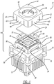
- Figure 1 shows a camera arrangement 10 for a motor vehicle 12 (schematically illustrated as dashed lines in Figure 8 ) in accordance with an exemplary embodiment.
- the camera arrangement 10 includes a sealed enclosure assembly 14 that at least partially encloses a camera system 16.
- a heatsink 18 Operatively coupled to the camera system 16 is a heatsink 18 to facilitate thermal management of the camera system 16.
- the camera system 16 is configured to collect incoming light as data when mounted on the motor vehicle 12 (see Figure 8 ).
- the term "light” is used broadly and is understood to mean visible light, thermal scene energy or electromagnetic radiation in the infrared (IR) spectrum (IR light) or other detectable frequencies of electromagnetic radiation used in various camera system known to those skilled in the art.
- the camera system 16 collects incoming light in a vehicle running direction (e.g., forward direction) to collect images of a forward road environment while running and provides an image signal to an image processing unit that converts the image signal to a various kind of forward data that can be used by one or more other devices and/or control units for driving support.
- the camera system 16 is a thermal imaging night vision camera system that includes an optical arrangement adapted to focus incoming light in a vehicle running direction onto an infrared (IR) sensing arrangement.
- the IR sensing arrangement generates an output signal and the camera system 16 further includes processing electronics to process the output signal for assisting a vehicle driver in detecting, for example, a pedestrian(s), an animal(s), and/or the like.
- the sealed enclosure assembly 14 includes a front housing 20 enclosing, for example, a forward facing portion of the camera system 16, a retainer 22, a window 24, and a sealing element 26.
- the heatsink 18 is attached to the front housing via threaded fasteners 28 (e.g., screws, bolts, or the like).
- the front housing 20 has a housing opening 30 formed therethrough that is positioned in front of the camera system 16.
- the housing opening 30 is sized to permit light to pass through the housing opening 30 to the camera system 16, e.g., an optical arrangement of the camera system 16, for collecting, focusing, and/or processing the light.
- the window 24 is at least partially transparent to allow at least a portion of the light to pass through the window 24 to the camera system 16.
- the window 24 allows IR light to pass through the window 24 to impinge on the optical arrangement of the camera system 16.
- the sealing element 26 is disposed between the window 24 and the front housing 20.
- the sealing element 26 can be a seal (e.g., ring type seal or the like), a gasket, a pressure sensitive adhesive, or the like.
- the sealing element 26 sealingly interfaces with the window 24 and the front housing 20 to provide a moisture-tight seal.
- the sealing element 26 is disposed laterally adjacent to and around the housing opening 30 and has a seal opening 32 that is aligned with the housing opening 30 to allow the light to pass by the sealing element 26 to the camera system 16.
- the retainer 22 is disposed adjacent to the window 24.
- the retainer 22 includes a plate 34 that defines a retainer opening 36 and that has a perimeter portion 38 surrounding the retainer opening 36.
- the plate 34 is disposed adjacent to the window 24 with the retainer opening 36 aligned with the housing opening 30 to allow the light to pass by the retainer 22 to the camera system 16.
- the retainer 22 includes a snapfit arrangement 40 that engages the front housing 20 to help hold the window 24 in place relative to the front housing 20 and the housing opening 30.
- the retainer 22 includes sidewalls 42 that extend rearwardly from the perimeter portion 38 of the plate 34.
- the sidewalls 42 define the snapfit arrangement 40 in which a plurality of slits or slots 44 are spaced apart and formed extending through the sidewalls 42 to define a plurality of cantilever clips 46.
- the cantilever clips 46 correspondingly have positive snapfit features 48 disposed distally on the cantilever clips 46 engaging recessed portions 50 formed in the front housing 20.
- the recessed portions 50 of the front housing 20 receive the positive snapfit features 48 when the retainer 22 is advanced towards and placed in position onto the front housing 20 to firmly hold the plate 34 of the retainer 22 against the outer surface of the window 24, thereby pressing the inside surface of the window 24 against the sealing element 26 to compress the sealing element 26 and form a good seal between the window 24 and the front housing 20.
- the front housing 20 includes raised inclined surfaces 51 adjacent to the recessed portions 50 to facilitate spreading of the cantilever clips 46 when the positive snapfit features 48 interfaced with the raised inclined surfaces 51 as the retainer 22 and the front housing 20 are moved together.
- the cantilever clips 46 snap back or return to their nominal position with the positive snapfit features 48 engaging the recessed portions 50 to couple (e.g., snapfit attach) the retainer 22 and the front housing 20 together.
- the retainer 22 is an external retainer 52 that mounts on an exterior 54 of the front housing 20 such that the retainer 22 is disposed outside of the front housing 20 with the plate 34 forward of the housing opening 30.
- the front housing 20 has forward projecting walls 56 with the recessed portions 50 on the exterior 54 of the forward projecting walls 56.
- the sidewalls 42 of the external retainer 52 extend rearwardly over the exterior 54 of the forward projecting walls 56.
- the positive snapfit features 48 of the cantilever clips 46 faced toward the exterior 54 of the front housing 20 so that the recessed portions 50 of the forward projecting walls 56 receive and retain the positive snapfit features 48 of the external retainer 52.
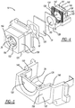
- the sealed enclosure assembly 140 includes a front housing 120, a sealing element 126, the window 24, a heater 128, and a retainer 122.
- the sealed enclosure assembly 140 shown in Figures 4-5 is similarly configured to the sealed enclosure assembly 14 shown in Figures 1-3 but with the exception that the sealed enclosure assembly 140 further includes the heater 128 and the retainer 122 is an internal retainer 152 that mounts inside on an interior 154 of the front housing 120 instead of on the front housing exterior.
- the heater 128 is disposed between the window 24 and the retainer 122 and is configured to heat the window 24.
- the heat 128 is configured to warm the window 24 during cold and/or wet weather conditions and to help keep the window 24 dry and free of ice buildup.
- the heater 128 is configured as a flat film resistive heater and directly interfaces with the window 24 and the retainer.
- the heater 128 is disposed laterally adjacent to the housing opening 30 and defines a heater opening 155 that is aligned with the housing opening 30 to allow the light to pass by the heater 128 to the camera system 16 (see Figure 1 ).
- the sealed enclosure assembly 14 may be similarly configured so as to include the heater 128.
- the sealing element 126 is illustrated having a substantially flat form with the seal opening 32 formed therethrough to allow light to pass by the sealing element 126 as described above in relation to the sealing element 26.
- the sealing element 126 performs substantially the same function as the sealing element 26 and is selected from the group consisting of a seal, a gasket, and/or a pressure sensitive adhesive.
- the internal retainer 152 includes a plate 134 that defines a retainer opening 136 and that has a perimeter portion 138 surrounding the retainer opening 136.
- the plate 134 is disposed adjacent to the window 24 with the retainer opening 136 aligned with the housing opening 30 to allow the light to pass by the retainer 122 to the camera system 16 (see Figure 1 ).
- the internal retainer 152 includes sidewalls 142 that extend rearwardly from the perimeter portion 138 of the plate 134.
- the sidewalls 142 define a snapfit arrangement 141 that includes a plurality of cantilever clips 146 with positive snapfit features 148 disposed distally on the cantilever clips 146 engaging recessed portions 150 formed in the front housing 120.
- the internal retainer 152 mounts inside the front housing 120 on the interior 154 with the plate 134 rearward of the housing opening 30.
- the sidewalls 142 are covered by the interior 154 of the front housing 120.
- the positive snapfit features 148 of the cantilever clips 146 faced toward the interior 154 of the front housing 120 so that the recessed portions 150 of the forward projecting walls 156 of the front housing 120 receive and retain the positive snapfit features 148 of the internal retainer 152 when the internal retainer 152 is advanced into position inside the interior 154 of the front housing 120.
- the cantilever clips 146 will bend inwardly as the positive snapfit features 148 are advanced over the distal portions of the front housing 120 adjacent to the recessed portions 150 and will snap in place into the recessed portions 150 when the internal retainer 152 is fully seated in position in the interior 154 of the front housing 120.
- the recessed portions 150 of the front housing 120 receive the positive snapfit features 148 to firmly hold the plate 134 of the retainer 122 against the inside surface of the window 24, thereby pressing the outside surface of the window 24 against the sealing element 126 to compress the sealing element 126 and form a good seal between the window 24 and the front housing 120.
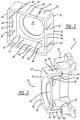
- the front housing 20 (and/or 120) of the camera arrangement 10 has one or more recessed portions 62 that correspondingly receive one or more positive snapfit features 64 of a snapfit arrangement 66 from a component 68 (e.g., front grill reinforcement structure or the like) of the motor vehicle 12 to mount the camera arrangement 10 on the component 68.
- the front housing 20, 120 includes raised portions 70 and 72 and the recessed portions 62 are correspondingly disposed between the raised portions 70 and 72.
- the recessed portions 62 include inclined surfaces 74 that facilitate spreading of the cantilever clips 76 of the component 68 when the positive snapfit features 64 interfaced with the inclined surfaces 74 as the camera arrangement 10 and the component 68 are moved together to position the camera arrangement 10 through the opening 78 of the component 68.
- the cantilever clips 76 snap back or return to their nominal position to couple (e.g., snapfit attach) the component 68 to the camera arrangement 10 such as illustrated in Figure 8 .
- the exemplary embodiments taught herein include a front housing that at least partially encloses a camera system and has a housing opening formed therethrough for allowing light to pass through to the camera system.
- the front housing is configured to engagingly receive a snapfit arrangement(s) from a window retainer that forms part of a sealed enclosure assembly system and/or from a component of a motor vehicle.
- the attachment means associated with the camera arrangement can be relatively quick, simple and inexpensive, without requiring any special tools to facilitate assembly of the camera arrangement and/or attachment of the camera arrangement to the motor vehicle.
Landscapes
- Engineering & Computer Science (AREA)
- Multimedia (AREA)
- Signal Processing (AREA)
- Physics & Mathematics (AREA)
- General Physics & Mathematics (AREA)
- Mechanical Engineering (AREA)
- Aviation & Aerospace Engineering (AREA)
- Electromagnetism (AREA)
- Studio Devices (AREA)
- Fittings On The Vehicle Exterior For Carrying Loads, And Devices For Holding Or Mounting Articles (AREA)
Claims (10)
- Kameraanordnung (10) für ein Kraftfahrzeug (12), wobei die Anordnung Folgendes umfasst:ein Frontgehäuse (20, 120), um ein Kamerasystem (16) zumindest teilweise einzuhausen, das eine Gehäuseöffnung (30) aufweist, die durch dieses hindurch ausgebildet ist, um zu ermöglichen, dass Licht durch das Kamerasystem (16) hindurchtritt;ein Fenster (24), das zumindest teilweise für das Licht durchlässig ist und die Gehäuseöffnung (30) abdeckt; undeine Rückhaltevorrichtung (22), die benachbart in Bezug auf das Fenster (24) angeordnet ist und eine Einschnappanordnung (40, 141) umfasst, die mit dem Frontgehäuse (20, 120) in Eingriff steht, um dabei zu helfen, das Fenster (24) in Bezug auf das Frontgehäuse (20, 120) an seinem Platz zu halten;wobei die Rückhaltevorrichtung (22) Folgendes umfasst:eine Platte (34, 134), die eine Rückhaltevorrichtungsöffnung (36, 136) definiert, die mit der Gehäuseöffnung (30) fluchtend ausgerichtet ist und einen Umfangsabschnitt (38, 138) aufweist, der die Rückhaltevorrichtungsöffnung (36, 136) umgibt; undSeitenwände (42, 142), die sich von dem Umfangsabschnitt (38, 138) im Allgemeinen quer zu der Platte (34, 134) erstrecken, wobei die Seitenwände (42, 142) die Einschnappanordnung (40, 140) definieren, die als eine Vielzahl auskragender Federklemmen (46, 146) ausgelegt ist und die entsprechend Formschluss-Einschnappelemente (48, 148) aufweist, die distal auf den auskragenden Federklemmen (46, 146) angeordnet sind, und wobei das Frontgehäuse (20, 120) vertiefte Abschnitte (50, 150) aufweist, die die Formschluss-Einschnappelemente (48, 148) aufnehmen,wobei die Rückhaltevorrichtung eine innere Rückhaltevorrichtung (152) ist, die an einer Innenseite (154) des Frontgehäuses (120) derart befestigt ist, dass die Rückhaltevorrichtung im Inneren des Frontgehäuses (120) angeordnet ist, wobei die Platte (134) hinter der Gehäuseöffnung (30) ist.
- Kameraanordnung (10) nach Anspruch 1, wobei das Fenster (24) zwischen dem Frontgehäuse (20, 120) und der Rückhaltevorrichtung (22) angeordnet ist.
- Kameraanordnung (10) nach Anspruch 2, die ferner ein Dichtelement (26, 126) umfasst, das zwischen dem Fenster (24) und dem Frontgehäuse (20, 120) angeordnet ist.
- Kameraanordnung (10) nach Anspruch 3, wobei das Dichtelement (26, 126) aus der aus einer Versiegelung, einer Dichtung und einem druckempfindlichen Haftmittel bestehenden Gruppe ausgewählt ist.
- Kameraanordnung (10) nach Anspruch 3, wobei das Dichtelement (26, 126) an das Fenster (24) und das Frontgehäuse (20, 120) dichtend anschließt.
- Kameraanordnung (10) nach Anspruch 3, wobei das Dichtelement (26, 126) lateral benachbart in Bezug auf die Gehäuseöffnung (30) angeordnet ist und eine Dichtungsöffnung (32) definiert, die mit der Gehäuseöffnung (30) fluchtend ausgerichtet ist, um zu ermöglichen, dass das Licht an dem Dichtelement (26) vorbei zu dem Kamerasystem (16) hindurchtritt.
- Kameraanordnung (10) nach Anspruch 1, die ferner ein Heizelement (128) umfasst, das zwischen dem Fenster (24) und der Rückhaltevorrichtung (22) angeordnet ist.
- Kameraanordnung (10) nach Anspruch 7, wobei das Heizelement (128) direkt an das Fenster (24) und die Rückhaltevorrichtung (22) anschließt.
- Kameraanordnung (10) nach Anspruch 7, wobei das Heizelement (128) lateral benachbart in Bezug auf die Gehäuseöffnung (30) angeordnet ist und eine Heizelementöffnung (155) definiert, die mit der Gehäuseöffnung (30) fluchtend ausgerichtet ist, um zu ermöglichen, dass das Licht an dem Heizelement (128) vorbei zu dem Kamerasystem (16) hindurchtritt.
- Kameraanordnung (10) nach Anspruch 1, wobei die Seitenwände (142) der inneren Rückhaltevorrichtung (152) sich nach hinten erstrecken und zumindest von einem Abschnitt des Inneren (154) des Frontgehäuses (120) bedeckt sind.
Applications Claiming Priority (2)
| Application Number | Priority Date | Filing Date | Title |
|---|---|---|---|
| US15/130,133 US10369936B2 (en) | 2016-04-15 | 2016-04-15 | Camera arrangements for motor vehicles |
| PCT/US2017/026265 WO2017180412A1 (en) | 2016-04-15 | 2017-04-06 | Camera arrangements for motor vehicles |
Publications (3)
| Publication Number | Publication Date |
|---|---|
| EP3426524A1 EP3426524A1 (de) | 2019-01-16 |
| EP3426524A4 EP3426524A4 (de) | 2020-01-08 |
| EP3426524B1 true EP3426524B1 (de) | 2021-09-01 |
Family
ID=60040262
Family Applications (1)
| Application Number | Title | Priority Date | Filing Date |
|---|---|---|---|
| EP17782865.4A Active EP3426524B1 (de) | 2016-04-15 | 2017-04-06 | Kameraanordnungen für kraftfahrzeuge |
Country Status (4)
| Country | Link |
|---|---|
| US (1) | US10369936B2 (de) |
| EP (1) | EP3426524B1 (de) |
| CN (1) | CN109070811B (de) |
| WO (1) | WO2017180412A1 (de) |
Families Citing this family (12)
| Publication number | Priority date | Publication date | Assignee | Title |
|---|---|---|---|---|
| US12060006B2 (en) * | 2012-01-24 | 2024-08-13 | SMR Patents S.à.r.l. | Camera cradle assembly for rear view device |
| US11453366B2 (en) * | 2018-11-06 | 2022-09-27 | Motherson Innovations Company Limited | Heatable device for use with a vehicle-mounted image acquisition unit |
| WO2020139471A1 (en) * | 2018-12-28 | 2020-07-02 | Flir Commercial Systems, Inc. | Integrated camera with embedded heater systems and methods |
| CN111600455A (zh) | 2019-02-21 | 2020-08-28 | 三赢科技(深圳)有限公司 | 音圈马达及应用其的摄像头模组和电子装置 |
| DE102020108771A1 (de) * | 2020-03-30 | 2021-09-30 | Connaught Electronics Ltd. | Verfahren zur Montage einer Kamera für ein Fahrzeug, Vormontagemodul für eine Kamera, sowie Kamera |
| US12253740B2 (en) * | 2020-12-08 | 2025-03-18 | Waymo Llc | Impact resistant heated window mount for thermal camera |
| CN116635782B (zh) | 2020-12-22 | 2026-04-03 | 金泰克斯公司 | 带加热元件的成像器组件 |
| US12581178B2 (en) * | 2021-06-22 | 2026-03-17 | Motherson Innovations Company Limited | Camera assembly arrangement for vehicle rear view cover and rear view device therewith |
| DE102021116131B4 (de) * | 2021-06-22 | 2024-07-25 | Motherson Innovations Company Limited | Kamerabaugruppenanordnung für eine Fahrzeugrückblickverkleidung |
| USD1069879S1 (en) * | 2023-02-27 | 2025-04-08 | e-con Systems India Private Limited | Camera enclosure |
| US12594893B2 (en) | 2024-06-14 | 2026-04-07 | Fca Us Llc | Vehicle camera mounting structure |
| USD1108528S1 (en) * | 2024-06-27 | 2026-01-06 | Amphenol Corporation | Camera housing assembly |
Family Cites Families (10)
| Publication number | Priority date | Publication date | Assignee | Title |
|---|---|---|---|---|
| US6832043B2 (en) | 2002-12-20 | 2004-12-14 | Eastman Kodak Company | Camera lens module having recyclable lens barrel cap |
| DE10319176A1 (de) | 2003-04-29 | 2004-11-18 | Robert Bosch Gmbh | Vorrichtung zur Kühlung einer Kamera |
| FR2861348B1 (fr) * | 2003-10-23 | 2006-12-08 | Valeo Systemes Dessuyage | Montage d'une camera de vision arriere dans un boitier de protection comportant une fenetre de vision |
| US7329869B2 (en) | 2005-09-13 | 2008-02-12 | Autoliv Development Ab | Camera system |
| JP4844829B2 (ja) * | 2006-10-27 | 2011-12-28 | ソニー株式会社 | カメラモジュール |
| JP4497193B2 (ja) | 2007-11-09 | 2010-07-07 | ソニー株式会社 | カメラ取り付け構造、カメラ取り付け方法および車両の外装パネル部品 |
| US7734171B2 (en) | 2008-01-29 | 2010-06-08 | Autoliv Asp, Inc. | Snap-in retainer for a sensor system |
| JP5333250B2 (ja) * | 2009-01-23 | 2013-11-06 | 株式会社ニコン | 撮像装置 |
| US8861951B2 (en) | 2011-12-05 | 2014-10-14 | Flextronics Ap, Llc | Two part camera module |
| US9621769B2 (en) | 2014-06-11 | 2017-04-11 | Magna Electronics Inc. | Camera module for vehicle vision system |
-
2016
- 2016-04-15 US US15/130,133 patent/US10369936B2/en active Active
-
2017
- 2017-04-06 CN CN201780023721.6A patent/CN109070811B/zh active Active
- 2017-04-06 EP EP17782865.4A patent/EP3426524B1/de active Active
- 2017-04-06 WO PCT/US2017/026265 patent/WO2017180412A1/en not_active Ceased
Also Published As
| Publication number | Publication date |
|---|---|
| EP3426524A1 (de) | 2019-01-16 |
| US20170297504A1 (en) | 2017-10-19 |
| CN109070811B (zh) | 2021-10-26 |
| EP3426524A4 (de) | 2020-01-08 |
| WO2017180412A1 (en) | 2017-10-19 |
| US10369936B2 (en) | 2019-08-06 |
| CN109070811A (zh) | 2018-12-21 |
Similar Documents
| Publication | Publication Date | Title |
|---|---|---|
| EP3426524B1 (de) | Kameraanordnungen für kraftfahrzeuge | |
| US11964617B2 (en) | Vehicular vision system with forward viewing camera module | |
| US20250240533A1 (en) | Vehicular camera module | |
| CN108696678B (zh) | 相机模块 | |
| JP6786629B2 (ja) | 自動車の光学検出システムを清掃するための装置 | |
| US20130107110A1 (en) | Camera module | |
| EP2965951B1 (de) | Vorrichtung zur verwendung im zusammenhang mit einem fahrzeug | |
| KR102363712B1 (ko) | 차량의 지원 시스템 | |
| US7734171B2 (en) | Snap-in retainer for a sensor system | |
| EP1056374A1 (de) | Auf einem kraftfahrzeug montierte optische anordnung | |
| SE526424C2 (sv) | Aktivt mörkerseendesystem för ett inre passagerarutrymme hos ett fordon samt metod för att styra nämnda system | |
| US20090289811A1 (en) | Display system and vehicle having the same | |
| US6795237B1 (en) | Overhead console active night vision system for an interior cabin of a vehicle | |
| US10057469B2 (en) | Camera shutter arrangements and camera arrangements including camera shutter arrangements | |
| US20190146066A1 (en) | Vehicle lidar sensing system with sensor module | |
| CN111301302B (zh) | 机动车-传感器件组合模块 | |
| CN113853323B (zh) | 车载相机设备 | |
| TWI777721B (zh) | 後視鏡系統及車輛 | |
| EP1626290A1 (de) | BILDERFASSUNGSMODUL, DAS F R DIE BERWACHUNG DES ûUSSEREN UMFELDS EINES FAHRZEUGS BESTIMMT IST | |
| KR102696361B1 (ko) | 차량에 장착하기 위한 카메라 배열체 | |
| US20190263330A1 (en) | Driver assist system | |
| KR20090022911A (ko) | 자동차 후방 감시 시스템 | |
| JPH06344827A (ja) | 車両左右方向死角モニター | |
| KR20170142286A (ko) | 자동차용 전방향 감시카메라 | |
| KR200443452Y1 (ko) | 차량용 후방감지카메라의 부착구조 |
Legal Events
| Date | Code | Title | Description |
|---|---|---|---|
| STAA | Information on the status of an ep patent application or granted ep patent |
Free format text: STATUS: THE INTERNATIONAL PUBLICATION HAS BEEN MADE |
|
| PUAI | Public reference made under article 153(3) epc to a published international application that has entered the european phase |
Free format text: ORIGINAL CODE: 0009012 |
|
| STAA | Information on the status of an ep patent application or granted ep patent |
Free format text: STATUS: REQUEST FOR EXAMINATION WAS MADE |
|
| 17P | Request for examination filed |
Effective date: 20181011 |
|
| AK | Designated contracting states |
Kind code of ref document: A1 Designated state(s): AL AT BE BG CH CY CZ DE DK EE ES FI FR GB GR HR HU IE IS IT LI LT LU LV MC MK MT NL NO PL PT RO RS SE SI SK SM TR |
|
| AX | Request for extension of the european patent |
Extension state: BA ME |
|
| DAV | Request for validation of the european patent (deleted) | ||
| DAX | Request for extension of the european patent (deleted) | ||
| A4 | Supplementary search report drawn up and despatched |
Effective date: 20191209 |
|
| RIC1 | Information provided on ipc code assigned before grant |
Ipc: G03B 17/02 20060101ALI20191203BHEP Ipc: H04N 5/33 20060101ALI20191203BHEP Ipc: G03B 17/55 20060101ALI20191203BHEP Ipc: H04N 5/225 20060101ALI20191203BHEP Ipc: B60R 11/04 20060101AFI20191203BHEP |
|
| STAA | Information on the status of an ep patent application or granted ep patent |
Free format text: STATUS: EXAMINATION IS IN PROGRESS |
|
| 17Q | First examination report despatched |
Effective date: 20201103 |
|
| RAP1 | Party data changed (applicant data changed or rights of an application transferred) |
Owner name: VEONEER US, INC. |
|
| GRAP | Despatch of communication of intention to grant a patent |
Free format text: ORIGINAL CODE: EPIDOSNIGR1 |
|
| STAA | Information on the status of an ep patent application or granted ep patent |
Free format text: STATUS: GRANT OF PATENT IS INTENDED |
|
| INTG | Intention to grant announced |
Effective date: 20210514 |
|
| GRAS | Grant fee paid |
Free format text: ORIGINAL CODE: EPIDOSNIGR3 |
|
| GRAA | (expected) grant |
Free format text: ORIGINAL CODE: 0009210 |
|
| STAA | Information on the status of an ep patent application or granted ep patent |
Free format text: STATUS: THE PATENT HAS BEEN GRANTED |
|
| AK | Designated contracting states |
Kind code of ref document: B1 Designated state(s): AL AT BE BG CH CY CZ DE DK EE ES FI FR GB GR HR HU IE IS IT LI LT LU LV MC MK MT NL NO PL PT RO RS SE SI SK SM TR |
|
| REG | Reference to a national code |
Ref country code: GB Ref legal event code: FG4D |
|
| REG | Reference to a national code |
Ref country code: CH Ref legal event code: EP Ref country code: AT Ref legal event code: REF Ref document number: 1425908 Country of ref document: AT Kind code of ref document: T Effective date: 20210915 |
|
| REG | Reference to a national code |
Ref country code: DE Ref legal event code: R096 Ref document number: 602017045261 Country of ref document: DE |
|
| REG | Reference to a national code |
Ref country code: IE Ref legal event code: FG4D |
|
| REG | Reference to a national code |
Ref country code: LT Ref legal event code: MG9D |
|
| REG | Reference to a national code |
Ref country code: NL Ref legal event code: MP Effective date: 20210901 |
|
| PG25 | Lapsed in a contracting state [announced via postgrant information from national office to epo] |
Ref country code: RS Free format text: LAPSE BECAUSE OF FAILURE TO SUBMIT A TRANSLATION OF THE DESCRIPTION OR TO PAY THE FEE WITHIN THE PRESCRIBED TIME-LIMIT Effective date: 20210901 Ref country code: SE Free format text: LAPSE BECAUSE OF FAILURE TO SUBMIT A TRANSLATION OF THE DESCRIPTION OR TO PAY THE FEE WITHIN THE PRESCRIBED TIME-LIMIT Effective date: 20210901 Ref country code: HR Free format text: LAPSE BECAUSE OF FAILURE TO SUBMIT A TRANSLATION OF THE DESCRIPTION OR TO PAY THE FEE WITHIN THE PRESCRIBED TIME-LIMIT Effective date: 20210901 Ref country code: LT Free format text: LAPSE BECAUSE OF FAILURE TO SUBMIT A TRANSLATION OF THE DESCRIPTION OR TO PAY THE FEE WITHIN THE PRESCRIBED TIME-LIMIT Effective date: 20210901 Ref country code: BG Free format text: LAPSE BECAUSE OF FAILURE TO SUBMIT A TRANSLATION OF THE DESCRIPTION OR TO PAY THE FEE WITHIN THE PRESCRIBED TIME-LIMIT Effective date: 20211201 Ref country code: NO Free format text: LAPSE BECAUSE OF FAILURE TO SUBMIT A TRANSLATION OF THE DESCRIPTION OR TO PAY THE FEE WITHIN THE PRESCRIBED TIME-LIMIT Effective date: 20211201 Ref country code: ES Free format text: LAPSE BECAUSE OF FAILURE TO SUBMIT A TRANSLATION OF THE DESCRIPTION OR TO PAY THE FEE WITHIN THE PRESCRIBED TIME-LIMIT Effective date: 20210901 Ref country code: FI Free format text: LAPSE BECAUSE OF FAILURE TO SUBMIT A TRANSLATION OF THE DESCRIPTION OR TO PAY THE FEE WITHIN THE PRESCRIBED TIME-LIMIT Effective date: 20210901 |
|
| REG | Reference to a national code |
Ref country code: AT Ref legal event code: MK05 Ref document number: 1425908 Country of ref document: AT Kind code of ref document: T Effective date: 20210901 |
|
| PG25 | Lapsed in a contracting state [announced via postgrant information from national office to epo] |
Ref country code: PL Free format text: LAPSE BECAUSE OF FAILURE TO SUBMIT A TRANSLATION OF THE DESCRIPTION OR TO PAY THE FEE WITHIN THE PRESCRIBED TIME-LIMIT Effective date: 20210901 Ref country code: LV Free format text: LAPSE BECAUSE OF FAILURE TO SUBMIT A TRANSLATION OF THE DESCRIPTION OR TO PAY THE FEE WITHIN THE PRESCRIBED TIME-LIMIT Effective date: 20210901 Ref country code: GR Free format text: LAPSE BECAUSE OF FAILURE TO SUBMIT A TRANSLATION OF THE DESCRIPTION OR TO PAY THE FEE WITHIN THE PRESCRIBED TIME-LIMIT Effective date: 20211202 |
|
| PG25 | Lapsed in a contracting state [announced via postgrant information from national office to epo] |
Ref country code: AT Free format text: LAPSE BECAUSE OF FAILURE TO SUBMIT A TRANSLATION OF THE DESCRIPTION OR TO PAY THE FEE WITHIN THE PRESCRIBED TIME-LIMIT Effective date: 20210901 |
|
| PG25 | Lapsed in a contracting state [announced via postgrant information from national office to epo] |
Ref country code: IS Free format text: LAPSE BECAUSE OF FAILURE TO SUBMIT A TRANSLATION OF THE DESCRIPTION OR TO PAY THE FEE WITHIN THE PRESCRIBED TIME-LIMIT Effective date: 20220101 Ref country code: SM Free format text: LAPSE BECAUSE OF FAILURE TO SUBMIT A TRANSLATION OF THE DESCRIPTION OR TO PAY THE FEE WITHIN THE PRESCRIBED TIME-LIMIT Effective date: 20210901 Ref country code: SK Free format text: LAPSE BECAUSE OF FAILURE TO SUBMIT A TRANSLATION OF THE DESCRIPTION OR TO PAY THE FEE WITHIN THE PRESCRIBED TIME-LIMIT Effective date: 20210901 Ref country code: RO Free format text: LAPSE BECAUSE OF FAILURE TO SUBMIT A TRANSLATION OF THE DESCRIPTION OR TO PAY THE FEE WITHIN THE PRESCRIBED TIME-LIMIT Effective date: 20210901 Ref country code: PT Free format text: LAPSE BECAUSE OF FAILURE TO SUBMIT A TRANSLATION OF THE DESCRIPTION OR TO PAY THE FEE WITHIN THE PRESCRIBED TIME-LIMIT Effective date: 20220103 Ref country code: NL Free format text: LAPSE BECAUSE OF FAILURE TO SUBMIT A TRANSLATION OF THE DESCRIPTION OR TO PAY THE FEE WITHIN THE PRESCRIBED TIME-LIMIT Effective date: 20210901 Ref country code: EE Free format text: LAPSE BECAUSE OF FAILURE TO SUBMIT A TRANSLATION OF THE DESCRIPTION OR TO PAY THE FEE WITHIN THE PRESCRIBED TIME-LIMIT Effective date: 20210901 Ref country code: CZ Free format text: LAPSE BECAUSE OF FAILURE TO SUBMIT A TRANSLATION OF THE DESCRIPTION OR TO PAY THE FEE WITHIN THE PRESCRIBED TIME-LIMIT Effective date: 20210901 Ref country code: AL Free format text: LAPSE BECAUSE OF FAILURE TO SUBMIT A TRANSLATION OF THE DESCRIPTION OR TO PAY THE FEE WITHIN THE PRESCRIBED TIME-LIMIT Effective date: 20210901 |
|
| REG | Reference to a national code |
Ref country code: DE Ref legal event code: R097 Ref document number: 602017045261 Country of ref document: DE |
|
| PLBE | No opposition filed within time limit |
Free format text: ORIGINAL CODE: 0009261 |
|
| STAA | Information on the status of an ep patent application or granted ep patent |
Free format text: STATUS: NO OPPOSITION FILED WITHIN TIME LIMIT |
|
| PG25 | Lapsed in a contracting state [announced via postgrant information from national office to epo] |
Ref country code: IT Free format text: LAPSE BECAUSE OF FAILURE TO SUBMIT A TRANSLATION OF THE DESCRIPTION OR TO PAY THE FEE WITHIN THE PRESCRIBED TIME-LIMIT Effective date: 20210901 Ref country code: DK Free format text: LAPSE BECAUSE OF FAILURE TO SUBMIT A TRANSLATION OF THE DESCRIPTION OR TO PAY THE FEE WITHIN THE PRESCRIBED TIME-LIMIT Effective date: 20210901 |
|
| 26N | No opposition filed |
Effective date: 20220602 |
|
| PG25 | Lapsed in a contracting state [announced via postgrant information from national office to epo] |
Ref country code: SI Free format text: LAPSE BECAUSE OF FAILURE TO SUBMIT A TRANSLATION OF THE DESCRIPTION OR TO PAY THE FEE WITHIN THE PRESCRIBED TIME-LIMIT Effective date: 20210901 |
|
| REG | Reference to a national code |
Ref country code: CH Ref legal event code: PL |
|
| REG | Reference to a national code |
Ref country code: BE Ref legal event code: MM Effective date: 20220430 |
|
| REG | Reference to a national code |
Ref country code: DE Ref legal event code: R081 Ref document number: 602017045261 Country of ref document: DE Owner name: VEONEER US, LLC (N.D.GES.D. STAATES DELAWARE),, US Free format text: FORMER OWNER: VEONEER US, INC., SOUTHFIELD, MICH., US Ref country code: DE Ref legal event code: R081 Ref document number: 602017045261 Country of ref document: DE Owner name: MAGNA ELECTRONICS, LLC (N.D.GES.D. STAATES DEL, US Free format text: FORMER OWNER: VEONEER US, INC., SOUTHFIELD, MICH., US |
|
| PG25 | Lapsed in a contracting state [announced via postgrant information from national office to epo] |
Ref country code: MC Free format text: LAPSE BECAUSE OF FAILURE TO SUBMIT A TRANSLATION OF THE DESCRIPTION OR TO PAY THE FEE WITHIN THE PRESCRIBED TIME-LIMIT Effective date: 20210901 Ref country code: LU Free format text: LAPSE BECAUSE OF NON-PAYMENT OF DUE FEES Effective date: 20220406 Ref country code: LI Free format text: LAPSE BECAUSE OF NON-PAYMENT OF DUE FEES Effective date: 20220430 Ref country code: CH Free format text: LAPSE BECAUSE OF NON-PAYMENT OF DUE FEES Effective date: 20220430 |
|
| PG25 | Lapsed in a contracting state [announced via postgrant information from national office to epo] |
Ref country code: BE Free format text: LAPSE BECAUSE OF NON-PAYMENT OF DUE FEES Effective date: 20220430 |
|
| PG25 | Lapsed in a contracting state [announced via postgrant information from national office to epo] |
Ref country code: IE Free format text: LAPSE BECAUSE OF NON-PAYMENT OF DUE FEES Effective date: 20220406 |
|
| REG | Reference to a national code |
Ref country code: DE Ref legal event code: R081 Ref document number: 602017045261 Country of ref document: DE Owner name: MAGNA ELECTRONICS, LLC (N.D.GES.D. STAATES DEL, US Free format text: FORMER OWNER: VEONEER US, LLC (N.D.GES.D. STAATES DELAWARE), SOUTHFIELD, MI, US |
|
| PG25 | Lapsed in a contracting state [announced via postgrant information from national office to epo] |
Ref country code: HU Free format text: LAPSE BECAUSE OF FAILURE TO SUBMIT A TRANSLATION OF THE DESCRIPTION OR TO PAY THE FEE WITHIN THE PRESCRIBED TIME-LIMIT; INVALID AB INITIO Effective date: 20170406 |
|
| PG25 | Lapsed in a contracting state [announced via postgrant information from national office to epo] |
Ref country code: MK Free format text: LAPSE BECAUSE OF FAILURE TO SUBMIT A TRANSLATION OF THE DESCRIPTION OR TO PAY THE FEE WITHIN THE PRESCRIBED TIME-LIMIT Effective date: 20210901 Ref country code: CY Free format text: LAPSE BECAUSE OF FAILURE TO SUBMIT A TRANSLATION OF THE DESCRIPTION OR TO PAY THE FEE WITHIN THE PRESCRIBED TIME-LIMIT Effective date: 20210901 |
|
| PG25 | Lapsed in a contracting state [announced via postgrant information from national office to epo] |
Ref country code: MT Free format text: LAPSE BECAUSE OF FAILURE TO SUBMIT A TRANSLATION OF THE DESCRIPTION OR TO PAY THE FEE WITHIN THE PRESCRIBED TIME-LIMIT Effective date: 20210901 |
|
| PGFP | Annual fee paid to national office [announced via postgrant information from national office to epo] |
Ref country code: DE Payment date: 20250417 Year of fee payment: 9 |
|
| PGFP | Annual fee paid to national office [announced via postgrant information from national office to epo] |
Ref country code: GB Payment date: 20250424 Year of fee payment: 9 |
|
| PGFP | Annual fee paid to national office [announced via postgrant information from national office to epo] |
Ref country code: FR Payment date: 20250422 Year of fee payment: 9 |
|
| PG25 | Lapsed in a contracting state [announced via postgrant information from national office to epo] |
Ref country code: TR Free format text: LAPSE BECAUSE OF FAILURE TO SUBMIT A TRANSLATION OF THE DESCRIPTION OR TO PAY THE FEE WITHIN THE PRESCRIBED TIME-LIMIT Effective date: 20210901 |