EP3431843B1 - Tiroir de valve - Google Patents
Tiroir de valve Download PDFInfo
- Publication number
- EP3431843B1 EP3431843B1 EP17461570.8A EP17461570A EP3431843B1 EP 3431843 B1 EP3431843 B1 EP 3431843B1 EP 17461570 A EP17461570 A EP 17461570A EP 3431843 B1 EP3431843 B1 EP 3431843B1
- Authority
- EP
- European Patent Office
- Prior art keywords
- spool
- land
- spool valve
- guiding
- housing
- Prior art date
- Legal status (The legal status is an assumption and is not a legal conclusion. Google has not performed a legal analysis and makes no representation as to the accuracy of the status listed.)
- Active
Links
Images


Classifications
-
- F—MECHANICAL ENGINEERING; LIGHTING; HEATING; WEAPONS; BLASTING
- F16—ENGINEERING ELEMENTS AND UNITS; GENERAL MEASURES FOR PRODUCING AND MAINTAINING EFFECTIVE FUNCTIONING OF MACHINES OR INSTALLATIONS; THERMAL INSULATION IN GENERAL
- F16K—VALVES; TAPS; COCKS; ACTUATING-FLOATS; DEVICES FOR VENTING OR AERATING
- F16K11/00—Multiple-way valves, e.g. mixing valves; Pipe fittings incorporating such valves
- F16K11/02—Multiple-way valves, e.g. mixing valves; Pipe fittings incorporating such valves with all movable sealing faces moving as one unit
- F16K11/06—Multiple-way valves, e.g. mixing valves; Pipe fittings incorporating such valves with all movable sealing faces moving as one unit comprising only sliding valves, i.e. sliding closure elements
- F16K11/065—Multiple-way valves, e.g. mixing valves; Pipe fittings incorporating such valves with all movable sealing faces moving as one unit comprising only sliding valves, i.e. sliding closure elements with linearly sliding closure members
- F16K11/07—Multiple-way valves, e.g. mixing valves; Pipe fittings incorporating such valves with all movable sealing faces moving as one unit comprising only sliding valves, i.e. sliding closure elements with linearly sliding closure members with cylindrical slides
- F16K11/0708—Multiple-way valves, e.g. mixing valves; Pipe fittings incorporating such valves with all movable sealing faces moving as one unit comprising only sliding valves, i.e. sliding closure elements with linearly sliding closure members with cylindrical slides comprising means to avoid jamming of the slide or means to modify the flow
-
- Y—GENERAL TAGGING OF NEW TECHNOLOGICAL DEVELOPMENTS; GENERAL TAGGING OF CROSS-SECTIONAL TECHNOLOGIES SPANNING OVER SEVERAL SECTIONS OF THE IPC; TECHNICAL SUBJECTS COVERED BY FORMER USPC CROSS-REFERENCE ART COLLECTIONS [XRACs] AND DIGESTS
- Y10—TECHNICAL SUBJECTS COVERED BY FORMER USPC
- Y10T—TECHNICAL SUBJECTS COVERED BY FORMER US CLASSIFICATION
- Y10T137/00—Fluid handling
- Y10T137/0318—Processes
- Y10T137/0402—Cleaning, repairing, or assembling
- Y10T137/0491—Valve or valve element assembling, disassembling, or replacing
- Y10T137/0502—Multi way valve
-
- Y—GENERAL TAGGING OF NEW TECHNOLOGICAL DEVELOPMENTS; GENERAL TAGGING OF CROSS-SECTIONAL TECHNOLOGIES SPANNING OVER SEVERAL SECTIONS OF THE IPC; TECHNICAL SUBJECTS COVERED BY FORMER USPC CROSS-REFERENCE ART COLLECTIONS [XRACs] AND DIGESTS
- Y10—TECHNICAL SUBJECTS COVERED BY FORMER USPC
- Y10T—TECHNICAL SUBJECTS COVERED BY FORMER US CLASSIFICATION
- Y10T137/00—Fluid handling
- Y10T137/8593—Systems
- Y10T137/86493—Multi-way valve unit
- Y10T137/86574—Supply and exhaust
- Y10T137/8667—Reciprocating valve
- Y10T137/86694—Piston valve
- Y10T137/8671—With annular passage [e.g., spool]
Definitions
- This disclosure relates to a spool for a spool valve, and a spool valve featuring the same. This disclosure also relates to a method of preventing deformation of a spool valve housing adjacent a control port.
- Such spool valves are often used in hydraulic systems for aerospace applications, for instance, in two stage servovalves.
- a typical spool valve 1 comprises a spool housing 2 having a spool cavity 3 defined by an inner surface 2a of the housing 2, and a spool 4 disposed within the spool cavity 3 having a plurality of lands 5 separated by a plurality of grooves 6.
- the spool 4 is moveable along its longitudinal axis L in response to actuation of the spool valve 1, and the lands 5 are in sliding contact with the inner surface 2a of the housing 2.
- the spool valve 1 further comprises a control port 7 passing through the inner surface 2a of the housing 2 in fluid communication with the spool cavity 3.
- a chamber 8 is defined between the groove 6, the land 5 and the inner surface 2a of the housing 2.
- the lands 5 have radially extending metering edges 9 (as are well-known in the art of spool valves) which permit or prevent fluid communication between the control port 7 and the chamber 8 depending on the longitudinal position of the spool 4 within the spool cavity 3. As shown in Figure 1a , the metering edges 9 are radially aligned with the edges of the control port 7, so no fluid communication is permitted between the control port 7 and the chamber 8.
- actuation of the spool valve 1 causing the spool 4 to move longitudinally (to the right as you look at the Figure) causing the metering edges 9 to become radially misaligned with the edges of the control port 7, which permits fluid communication between the control port 7 and the chamber 8.
- actuation of the spool valve 1 can be used to control fluid movement in a hydraulic system, such as a servovalve.
- the present disclosure aims to provide a spool that prevents the aforementioned spool housing deformation.
- the present disclosure relates to a spool valve in accordance with claim 1.
- land, groove and metering edge are well-known terms in the art of spool valves.
- the land is an increased diameter portion of the spool (compared to the groove) that blocks fluid flow through a spool valve and guides the spool as it moves in a housing of the spool valve;
- the groove is a reduced diameter portion of the spool (compared to the land) that allows fluid to flow around the spool and through the spool valve;
- the metering edge is the edge surface of the land that dictates whether fluid flow is blocked or allowed around/through the spool valve.
- substantially radially means that within the scope of this disclosure, in some embodiments, the metering edge extends in a purely radial direction (i.e. perpendicular to the longitudinal axis), but in other embodiments, may be slightly offset from the radial direction. This could mean, for instance, that the metering edge is aligned at an angle relative to the radial axis (e.g. leaning radially inwardly towards the groove) or has a camber (e.g. within manufacturing tolerances).
- substantially flush means that within the scope of the disclosure, in some embodiments, the guiding surfaces are precisely flush with the circumferential surface (within manufacturing tolerances), but in other embodiments may be slightly offset below the circumferential surface.
- the guiding section allowing fluid communication between the groove and the metering edge of the land, it is meant that at least a portion of the metering surface is exposed to the groove, such that fluid communication between the groove and the metering edge is not impeded by the guiding section. In other words, the guiding section does not fully cover the metering edge.
- the guiding section provides support against the spool housing when in use in a spool valve, which can prevent housing deformation (such as described above in the Background section).
- the web includes a surface, connecting adjacent guiding surfaces that is recessed radially inward from the circumferential surface. In this manner, the web provides a connecting surface between the adjacent guiding surfaces that forms a "pocket", or in other words, a portion of the metering edge that is exposed to the groove.
- the web includes a radially extending surface, which is planar, between the connecting surface and the groove.
- the connecting surface is a concave surface that may be contiguous with the adjacent metering edge.
- the concave surface may be curved.
- the recessed connecting surface need not be concave, and could be flat or convex instead, as long as a portion of the metering edge is exposed to the groove.
- the plurality of guiding surfaces are evenly spaced around the longitudinal axis of the spool.
- the plurality of guiding surfaces comprises at least three guiding surfaces. In further embodiments, the plurality of guiding surfaces comprises between three to six guiding surfaces, or in other words, any of three guiding surfaces, four guiding surfaces, five guiding surfaces or six guiding surfaces.
- the land comprises two opposing metering edges and two opposing guiding sections.
- any of the above spool valves there a plurality of pairs of lands, such as two pairs, wherein the lands in each pair are separated by a spacer groove and each land has a respective guiding section.
- the metering edges and guiding sections of the lands in each pair oppose each other.
- the spool comprises steel, such as a soft steel, and outer surfaces, such as the guiding surfaces, circumferential surfaces and/or the metering edges comprise a hardened steel.
- the present disclosure relates to a method of preventing deformation of a spool valve housing adjacent a control port in accordance with claim 10.
- FIG. 2 schematically illustrates an exemplary spool for a spool valve in accordance with an embodiment of the present disclosure.
- Spool 10 has a longitudinal axis L and comprises a plurality of lands 12 and grooves 14 spaced axially along the spool 10 and a plurality of guiding sections 16 located between the lands 12 and grooves 14.
- Lands 12 each include a radially extending metering edge 13 and a circumferential surface 15 circumscribing the spool 10.
- the "spacer groove” 19 is not present, and the circumferential surface 15 extends between two opposing guiding sections 16 forming a single land 12 with opposing guiding sections 16, rather than a separate pair of opposing lands 12 with a guiding section 16 each.
- the plurality of guiding sections 16 comprise a plurality of circumferentially spaced guiding surfaces 17 and a web 18 radially inward of the circumferential surface 15 connecting them.
- the guiding surfaces 17 extend axially and contiguously from the circumferential surface 15 of the land 12 and are flush therewith.
- the web 18 provides a curved surface 18a that connects circumferentially adjacent guiding surfaces 17. As shown in Figure 2 , this surface 8a curves radially inward providing a concave surface 8a. In this manner, the web 18 allows a portion of the metering edges 13 to be exposed to the grooves 14.
- the depicted web 18 or its particular shape is not an essential feature of the present disclosure, and, in arrangements outside the scope of the present invention, the guiding section 16 could instead feature discrete circumferentially spaced guiding surfaces 17 that are not connected to each other or a connecting web of any other suitable shape, as long as fluid communication is permitted between the grooves 14 and the metering edges 13. Nevertheless, a web may support guiding surfaces 17 and may make guiding surfaces 17 easier to manufacture, by allowing more simple machining of a portion of the land 12 to form them.
- any other suitable method for manufacturing the guiding section 16/guiding surfaces 17 is also within the scope of the disclosure, for instance, joining separate guiding sections 16/guiding surfaces 17 to lands 12, for instance by welding, or forming the guiding sections 16/guiding surfaces 17 onto the land 12, for instance by additive manufacturing.
- the depicted guiding sections 16 have six evenly spaced guiding surfaces 17 around the circumference of the spool axis L (i.e. at 60° intervals), which can provide adequate and even support to the housing 30 in the spool valve 20, as will become more clear from the description of spool valve operation in relation to Figures 3a-4b below.
- any number of guiding surfaces 17 can be used (as long as there are at least two), with any appropriate spacing around the land circumference (even or otherwise).
- two, three, four or five evenly spaced guiding surfaces 17 may be used instead of the six depicted. Even more guiding surfaces 17 could be used if extra support is required, however, there is a trade-off with ease of machining and weight considerations.
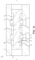
- Figures 3a-4b show a spool valve 20 that comprises the spool 10 disposed within a spool housing 30.
- the housing 30 has an inner surface 30a that defines a spool cavity 32.
- the spool 10 is disposed in the cavity 32 and is moveable along its longitudinal axis L therein. In this way, spool 10 can move in response to actuation of the spool valve 20.
- the circumferential surfaces 15 of the lands 12 and guiding surfaces 17 are in sliding contact with the housing inner surface 30a, and this contact keeps the spool 10 centred within the spool housing 30.
- sliding contact it is meant that the surfaces 15, 17 contact the inner surface 30a of the housing 30, but are permitted to slide against the inner surface 30a in response to actuation of the spool valve 20 (i.e. to permit movement of the spool 10).
- Chambers 33a, 33b and 33c are defined between respective grooves 14 and lands 12 and the inner surface 30a.
- the housing 30 includes control ports 34a, 34b passing through the housing 30 and having an opening through the inner surface 30a of the housing 30 such that the control ports 34a, 34b are in fluid communication with the spool cavity 32.
- a supply port 36 also passes through the housing 30 and has delivery channels 37a, 37b with openings through the inner surface 30a of the housing 30 to provide fluid communication with chambers 33a and 33c, respectively.
- a return port (not shown) is also provided through the housing 30 and is in fluid communication with chamber 33b in between the control ports 34.
- the spool valve 20 is in a neutral or closed position. In this position, fluid pressure on either side of the spool 10 (against metering edge 22a and metering edge 24a) is equal. This results in the spool 10 being unbiased and metering edges 13 being radially aligned with the edges of the control ports 34a, 34b, preventing fluid communication between the control ports 34a, 34b and chambers 33a, 33b, 33c.
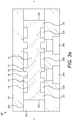
- guiding surfaces 17 remain in contact with the inner surface 30a. This permits fluid communication between control port 34a, chamber 33a and delivery channel 37a and permits fluid communication between the right hand control port 34b, chamber 33b and return port (not shown), whilst maintaining contact between the guiding surface 17 and the inner surface 30a of the housing 30. This permits pressurised fluid to flow from the control port 34a to the supply port 36 and from the control port 34b to the return port (not shown), whilst supporting the housing 30 to prevent deformation of the housing 30.
- Actuation of the spool valve 20 in the opposite direction is caused by providing a higher fluid pressure against metering edge 24a compared to metering edge 22a instead. This causes the spool 10 to move left, allowing fluid communication between control port 34b, chamber 33c and delivery channel 37b and between control port 34a, chamber 33b and return port (not shown). This permits pressurised fluid to flow from the control port 34a to the return port (not shown) and from the control port 34b to the supply port 36.
- spool valve 20 allows a relatively small, precise movement of spool 10 to result in a large movement of pressurised fluid for use in hydraulic systems.
- spool 10 comprises steel, such as a soft steel, and outer surfaces such as the guiding surfaces 17, circumferential surfaces 15 and metering edges 13 comprise a hardened steel, for instance, a case hardened steel. This provides a hard surface for contact with the inner surface 30a of the housing 30, and allows the metering edges 13 to cope with the high forces experienced due to high fluid pressures.
- spool 10 and/or outer surfaces may comprise a stainless steel to provide additional corrosion resistance against the fluid used in the spool valve 20.
Landscapes
- Engineering & Computer Science (AREA)
- General Engineering & Computer Science (AREA)
- Mechanical Engineering (AREA)
- Sliding Valves (AREA)
Claims (11)
- Tiroir de valve (20) comprenant :un boîtier (30) comportant une cavité de tiroir (32) à l'intérieur définie par une surface intérieure (30a) du boîtier (30) ; etun tiroir (10) ayant un axe longitudinal (L) disposé à l'intérieur de la cavité de tiroir (32), le tiroir (10) comprenant :une pluralité de plages (12) ayant chacune un bord de mesure s'étendant de manière sensiblement radiale (13) et une surface circonférentielle s'étendant axialement (15) ;une pluralité de rainures (14) séparant chacune de la pluralité de plages (12) ; etune section de guidage (16) située axialement entre au moins une plage (12) et une rainure adjacente (14), dans lequel :la section de guidage (16) comprend une pluralité de surfaces de guidage espacées circonférentiellement (17) étant sensiblement affleurantes et contiguës à la surface circonférentielle (15) de la plage (12) et une bande (18) s'étendant radialement vers l'intérieur de la surface circonférentielle (15) de la plage (12) et reliant la pluralité de surfaces de guidage (17) ; etla bande (18) comporte une surface de liaison (18a) reliant des surfaces de guidage adjacentes (17) qui est en retrait radialement vers l'intérieur depuis la surface circonférentielle (15), de sorte que la section de guidage (16) permet une communication fluidique entre la rainure (14) et le bord de mesure (13) de la plage (12) ;dans lequel le tiroir (10) est mobile le long de son axe longitudinal (L) en réponse à l'actionnement du tiroir de valve (20), et la surface circonférentielle (15) de la plage (12) et les surfaces de guidage (17) sont en contact coulissant avec la surface intérieure (30a) du boîtier (30) ; etle tiroir de valve (20) comprenant en outre :un orifice de commande (34a, 34b) traversant le boîtier (30) et en communication fluidique avec la cavité de tiroir (32) ; etune chambre (33a, 33b, 33c) définie entre la rainure (14), la plage (12) et la surface intérieure (30a) du boîtier (30) ; caractérisé en ce quele bord de mesure (13) de la plage (12) est configuré pour permettre ou empêcher une communication fluidique entre l'orifice de commande (34a, 34b) et la chambre (33a, 33b, 33c) en fonction de la position longitudinale du tiroir (10) à l'intérieur de la cavité de tiroir (32) ; et en ce quela bande (18) est définie par une surface plane s'étendant radialement.
- Tiroir de valve (20) selon la revendication 1, dans lequel le tiroir de valve (20) est configuré de sorte que, dans une position de tiroir neutre, le bord de mesure (13) est aligné radialement avec le bord de l'orifice de commande (34a, 34b) pour empêcher une communication fluidique entre l'orifice de commande (34a, 34b) et la chambre (33a, 33b, 33c).
- Tiroir de valve (20) selon la revendication 1 ou 2, dans lequel la surface de liaison (18a) est une surface concave incurvée.
- Tiroir de valve (20) selon une quelconque revendication précédente, dans lequel la pluralité de surfaces de guidage (17) sont espacées régulièrement, de manière circonférentielle, autour de l'axe longitudinal (L).
- Tiroir de valve (20) selon une quelconque revendication précédente, dans lequel la pluralité de surfaces de guidage (17) comprend au moins trois ou entre trois et six surfaces de guidage.
- Tiroir de valve (20) selon une quelconque revendication précédente, dans lequel la plage (12) comprend deux bords de mesure opposés (13) et deux sections de guidage opposées (16).
- Tiroir de valve (20) selon l'une quelconque des revendications 1 à 5, comprenant une pluralité de paires de plages (12), telles que deux paires, dans lequel les plages (12) dans chaque paire sont séparées par une rainure d'espacement (19) et chaque plage (12) a une section de guidage respective (16) .
- Tiroir de valve (20) selon la revendication 7, dans lequel les bords de mesure (13) et les sections de guidage (16) des plages (12) dans chaque paire s'opposent.
- Tiroir de valve (20) selon une quelconque revendication précédente, dans lequel le tiroir (10) comprend de l'acier et les surfaces de guidage (17), des surfaces circonférentielles (15) et des bords de mesure (13) comprennent un acier trempé.
- Procédé pour empêcher la déformation d'un boitier de tiroir de valve (30) adjacent à un orifice de commande (34a, 34b), comprenant :la fourniture d'une plage (12) d'un tiroir (10) avec une section de guidage (16) comprenant une pluralité de surfaces de guidage espacées circonférentiellement (17) étant sensiblement affleurantes et contiguës à la surface circonférentielle (15) de la plage (12) et une bande (18) s'étendant radialement vers l'intérieur de la surface circonférentielle (15) de la plage (12) et reliant la pluralité de surfaces de guidage (17), dans lequel la bande (18) comporte une surface de liaison (18a) reliant des surfaces de guidage adjacentes (17) qui est en retrait radialement vers l'intérieur depuis la surface circonférentielle (15), de sorte que la section de guidage (16) permet une communication fluidique entre la rainure (14) et le bord de mesure (13) de la plage (12) ;la disposition du tiroir (10) à l'intérieur d'une cavité de tiroir (32) dans le boîtier de tiroir de valve (30) de sorte que la surface circonférentielle (15) de la plage (12) et les surfaces de guidage (17) sont en contact coulissant avec une surface intérieure (30a) du boîtier (30) qui définit la cavité de tiroir (32), de sorte que, lorsque le bord de mesure (13) ouvre l'orifice de commande (34a, 34b), la surface intérieure (30a) du boîtier (30) est supportée par le contact avec les surfaces de guidage (17) ; et caractérisé parla configuration du bord de mesure (13) de la plage (12) pour permettre ou empêcher la communication fluidique entre l'orifice de commande (34a, 34b) et la chambre (33a, 33b, 33c) en fonction de la position longitudinale du tiroir (10) à l'intérieur la cavité de tiroir (32) ; et parla définition de la bande (18) par une surface plane s'étendant radialement.
- Procédé selon la revendication 10, comprenant en outre la configuration du tiroir de valve (20) de sorte que, dans une position de tiroir neutre, le bord de mesure (13) est aligné radialement avec le bord de l'orifice de commande (34a, 34b) pour empêcher une communication fluidique entre l'orifice de commande (34a, 34b) et la chambre (33a, 33b, 33c).
Priority Applications (2)
| Application Number | Priority Date | Filing Date | Title |
|---|---|---|---|
| EP17461570.8A EP3431843B1 (fr) | 2017-07-18 | 2017-07-18 | Tiroir de valve |
| US15/964,168 US10508746B2 (en) | 2017-07-18 | 2018-04-27 | Spool valve |
Applications Claiming Priority (1)
| Application Number | Priority Date | Filing Date | Title |
|---|---|---|---|
| EP17461570.8A EP3431843B1 (fr) | 2017-07-18 | 2017-07-18 | Tiroir de valve |
Publications (2)
| Publication Number | Publication Date |
|---|---|
| EP3431843A1 EP3431843A1 (fr) | 2019-01-23 |
| EP3431843B1 true EP3431843B1 (fr) | 2020-05-06 |
Family
ID=59384116
Family Applications (1)
| Application Number | Title | Priority Date | Filing Date |
|---|---|---|---|
| EP17461570.8A Active EP3431843B1 (fr) | 2017-07-18 | 2017-07-18 | Tiroir de valve |
Country Status (2)
| Country | Link |
|---|---|
| US (1) | US10508746B2 (fr) |
| EP (1) | EP3431843B1 (fr) |
Cited By (1)
| Publication number | Priority date | Publication date | Assignee | Title |
|---|---|---|---|---|
| DE102021111503A1 (de) | 2021-05-04 | 2022-11-10 | Schaeffler Technologies AG & Co. KG | Schieberventil |
Families Citing this family (6)
| Publication number | Priority date | Publication date | Assignee | Title |
|---|---|---|---|---|
| DE102019210488A1 (de) * | 2019-07-16 | 2021-01-21 | Robert Bosch Gmbh | Ventilkolben und Ventil mit dem Ventilkolben |
| WO2021128156A1 (fr) * | 2019-12-26 | 2021-07-01 | 博世力士乐(常州)有限公司 | Soupape à tiroir |
| US11680649B2 (en) * | 2020-11-16 | 2023-06-20 | Parker-Hannifin Corporstion | Proportional valve spool with linear flow gain |
| US11300222B1 (en) | 2020-11-18 | 2022-04-12 | Striped Monkey IP | Hydraulic valve spool assembly with metering land sections |
| US11788633B1 (en) | 2021-08-06 | 2023-10-17 | Caterpillar Inc. | Spools for spool valve assemblies and methods of fabricating spools |
| EP4390149A1 (fr) | 2022-12-23 | 2024-06-26 | Goodrich Actuation Systems Limited | Servovanne à deux étages |
Family Cites Families (17)
| Publication number | Priority date | Publication date | Assignee | Title |
|---|---|---|---|---|
| GB558363A (en) * | 1942-06-30 | 1944-01-03 | Keelavite Rotary Pumps & Motor | Improvements in or relating to fluid pressure apparatus |
| DE2038115B2 (de) * | 1970-07-31 | 1974-03-14 | G.L. Rexroth Gmbh, 8770 Lohr | Steuerventil mit geringem Durchflußwiderstand |
| US3717175A (en) * | 1971-04-08 | 1973-02-20 | Dowty Technical Dev Ltd | Selector valves |
| US3995532A (en) * | 1974-07-15 | 1976-12-07 | Caterpillar Tractor Co. | Proportional control valve with preconditioned inlet modulating relief valve |
| US4155535A (en) * | 1977-03-09 | 1979-05-22 | The Johns Hopkins University | Low axial force servo valve spool |
| US4245816A (en) * | 1978-04-19 | 1981-01-20 | Caterpillar Tractor Co. | Flow force balanced spool valve |
| DE3126269A1 (de) * | 1980-07-09 | 1982-04-01 | Barmag Barmer Maschinenfabrik Ag, 5630 Remscheid | "hydraulischer steuerkolben" |
| GB8717963D0 (en) * | 1987-07-29 | 1987-09-03 | Vickers Systems Ltd | Spool |
| DE3802672C2 (de) * | 1988-01-29 | 1993-12-16 | Danfoss As | Hydraulisches Steuerventil mit Druckfühleinrichtung |
| JPH0710650U (ja) * | 1993-07-26 | 1995-02-14 | 株式会社小松製作所 | 全油圧式ステアリングシステムの方向制御弁 |
| US6397890B1 (en) * | 1999-02-15 | 2002-06-04 | Case Corp. | Variable metering fluid control valve |
| DE10005290A1 (de) * | 2000-02-07 | 2001-08-09 | Mannesmann Rexroth Ag | Verfahren zur Herstellung eines Ventilkörpers |
| US6450194B1 (en) * | 2000-09-26 | 2002-09-17 | Case Corporation | Spool notch geometry for hydraulic spool valve |
| US6739293B2 (en) * | 2000-12-04 | 2004-05-25 | Sturman Industries, Inc. | Hydraulic valve actuation systems and methods |
| US6990996B2 (en) * | 2002-04-29 | 2006-01-31 | Sonnax Industries, Inc. | Torque converter clutch regulator valve assembly and method of installation |
| KR100793868B1 (ko) * | 2005-12-14 | 2008-01-10 | 현대자동차주식회사 | 무단 변속기 유압 제어시스템의 매뉴얼 밸브 |
| DE102007054138A1 (de) * | 2007-11-14 | 2009-05-28 | Hydac Filtertechnik Gmbh | Hydraulische Ventilvorrichtung |
-
2017
- 2017-07-18 EP EP17461570.8A patent/EP3431843B1/fr active Active
-
2018
- 2018-04-27 US US15/964,168 patent/US10508746B2/en active Active
Non-Patent Citations (1)
| Title |
|---|
| None * |
Cited By (1)
| Publication number | Priority date | Publication date | Assignee | Title |
|---|---|---|---|---|
| DE102021111503A1 (de) | 2021-05-04 | 2022-11-10 | Schaeffler Technologies AG & Co. KG | Schieberventil |
Also Published As
| Publication number | Publication date |
|---|---|
| US20190024806A1 (en) | 2019-01-24 |
| EP3431843A1 (fr) | 2019-01-23 |
| US10508746B2 (en) | 2019-12-17 |
Similar Documents
| Publication | Publication Date | Title |
|---|---|---|
| EP3431843B1 (fr) | Tiroir de valve | |
| CN105247259B (zh) | 滑阀 | |
| EP2827033B1 (fr) | Soupape de commutation | |
| KR101821827B1 (ko) | 일체화된 체크밸브를 가지는 비례 포핏밸브 | |
| EP2791515B1 (fr) | Tiroir de direction d'écoulement pour distributeur | |
| EP4019786B1 (fr) | Module de soupape multivoie de détection de charge | |
| CN108136499A (zh) | 通过加成制造方法制成的用于歧管组的歧管和阀外壳组合体 | |
| EP2115334B1 (fr) | Soupape à tiroir | |
| US20230349481A1 (en) | Device with a component and a valve housing | |
| US9429240B2 (en) | Valve device | |
| EP3892865B1 (fr) | Tiroir de distributeur hydraulique présentant des caractéristiques d'atténuation de force d'écoulement | |
| US5868216A (en) | Hydraulic rack-and-pinion steering assembly | |
| US10989324B2 (en) | Hydraulic spool valve | |
| EP3081820B1 (fr) | Actionneur hydraulique et son procédé de production | |
| US6994116B2 (en) | Distributing valve for the load-independent control of a hydraulic consumer in terms of direction and speed | |
| EP3348884B1 (fr) | Soupape d'amortissement hydraulique | |
| US6408877B2 (en) | Directional control valve | |
| RU2222702C2 (ru) | Четырехлинейный гидрораспределитель с плоским поворотным золотником | |
| US20190056036A1 (en) | Spool valve | |
| CN113302423B (zh) | 具有至少一个换向阀的阀组件以及具有这种阀组件的离合器装置 | |
| KR101690644B1 (ko) | 자동변속기용 슬리브 | |
| KR20180049088A (ko) | 유체압 실린더 | |
| RU2272182C1 (ru) | Четырехлинейный гидрораспределитель с плоским поворотным золотником | |
| US20090217983A1 (en) | Hydraulic valve assembly | |
| EP3377793B1 (fr) | Agencement d'indicateur d'actionneur de clapet |
Legal Events
| Date | Code | Title | Description |
|---|---|---|---|
| PUAI | Public reference made under article 153(3) epc to a published international application that has entered the european phase |
Free format text: ORIGINAL CODE: 0009012 |
|
| STAA | Information on the status of an ep patent application or granted ep patent |
Free format text: STATUS: THE APPLICATION HAS BEEN PUBLISHED |
|
| AK | Designated contracting states |
Kind code of ref document: A1 Designated state(s): AL AT BE BG CH CY CZ DE DK EE ES FI FR GB GR HR HU IE IS IT LI LT LU LV MC MK MT NL NO PL PT RO RS SE SI SK SM TR |
|
| AX | Request for extension of the european patent |
Extension state: BA ME |
|
| STAA | Information on the status of an ep patent application or granted ep patent |
Free format text: STATUS: REQUEST FOR EXAMINATION WAS MADE |
|
| 17P | Request for examination filed |
Effective date: 20190723 |
|
| RBV | Designated contracting states (corrected) |
Designated state(s): AL AT BE BG CH CY CZ DE DK EE ES FI FR GB GR HR HU IE IS IT LI LT LU LV MC MK MT NL NO PL PT RO RS SE SI SK SM TR |
|
| RIC1 | Information provided on ipc code assigned before grant |
Ipc: F16K 11/07 20060101AFI20191024BHEP |
|
| GRAP | Despatch of communication of intention to grant a patent |
Free format text: ORIGINAL CODE: EPIDOSNIGR1 |
|
| STAA | Information on the status of an ep patent application or granted ep patent |
Free format text: STATUS: GRANT OF PATENT IS INTENDED |
|
| INTG | Intention to grant announced |
Effective date: 20191210 |
|
| GRAS | Grant fee paid |
Free format text: ORIGINAL CODE: EPIDOSNIGR3 |
|
| GRAA | (expected) grant |
Free format text: ORIGINAL CODE: 0009210 |
|
| STAA | Information on the status of an ep patent application or granted ep patent |
Free format text: STATUS: THE PATENT HAS BEEN GRANTED |
|
| AK | Designated contracting states |
Kind code of ref document: B1 Designated state(s): AL AT BE BG CH CY CZ DE DK EE ES FI FR GB GR HR HU IE IS IT LI LT LU LV MC MK MT NL NO PL PT RO RS SE SI SK SM TR |
|
| REG | Reference to a national code |
Ref country code: GB Ref legal event code: FG4D |
|
| REG | Reference to a national code |
Ref country code: CH Ref legal event code: EP Ref country code: AT Ref legal event code: REF Ref document number: 1267282 Country of ref document: AT Kind code of ref document: T Effective date: 20200515 |
|
| REG | Reference to a national code |
Ref country code: IE Ref legal event code: FG4D |
|
| REG | Reference to a national code |
Ref country code: DE Ref legal event code: R096 Ref document number: 602017016183 Country of ref document: DE |
|
| REG | Reference to a national code |
Ref country code: LT Ref legal event code: MG4D |
|
| REG | Reference to a national code |
Ref country code: NL Ref legal event code: MP Effective date: 20200506 |
|
| PG25 | Lapsed in a contracting state [announced via postgrant information from national office to epo] |
Ref country code: SE Free format text: LAPSE BECAUSE OF FAILURE TO SUBMIT A TRANSLATION OF THE DESCRIPTION OR TO PAY THE FEE WITHIN THE PRESCRIBED TIME-LIMIT Effective date: 20200506 Ref country code: LT Free format text: LAPSE BECAUSE OF FAILURE TO SUBMIT A TRANSLATION OF THE DESCRIPTION OR TO PAY THE FEE WITHIN THE PRESCRIBED TIME-LIMIT Effective date: 20200506 Ref country code: NO Free format text: LAPSE BECAUSE OF FAILURE TO SUBMIT A TRANSLATION OF THE DESCRIPTION OR TO PAY THE FEE WITHIN THE PRESCRIBED TIME-LIMIT Effective date: 20200806 Ref country code: GR Free format text: LAPSE BECAUSE OF FAILURE TO SUBMIT A TRANSLATION OF THE DESCRIPTION OR TO PAY THE FEE WITHIN THE PRESCRIBED TIME-LIMIT Effective date: 20200807 Ref country code: PT Free format text: LAPSE BECAUSE OF FAILURE TO SUBMIT A TRANSLATION OF THE DESCRIPTION OR TO PAY THE FEE WITHIN THE PRESCRIBED TIME-LIMIT Effective date: 20200907 Ref country code: IS Free format text: LAPSE BECAUSE OF FAILURE TO SUBMIT A TRANSLATION OF THE DESCRIPTION OR TO PAY THE FEE WITHIN THE PRESCRIBED TIME-LIMIT Effective date: 20200906 Ref country code: FI Free format text: LAPSE BECAUSE OF FAILURE TO SUBMIT A TRANSLATION OF THE DESCRIPTION OR TO PAY THE FEE WITHIN THE PRESCRIBED TIME-LIMIT Effective date: 20200506 |
|
| PG25 | Lapsed in a contracting state [announced via postgrant information from national office to epo] |
Ref country code: LV Free format text: LAPSE BECAUSE OF FAILURE TO SUBMIT A TRANSLATION OF THE DESCRIPTION OR TO PAY THE FEE WITHIN THE PRESCRIBED TIME-LIMIT Effective date: 20200506 Ref country code: RS Free format text: LAPSE BECAUSE OF FAILURE TO SUBMIT A TRANSLATION OF THE DESCRIPTION OR TO PAY THE FEE WITHIN THE PRESCRIBED TIME-LIMIT Effective date: 20200506 Ref country code: HR Free format text: LAPSE BECAUSE OF FAILURE TO SUBMIT A TRANSLATION OF THE DESCRIPTION OR TO PAY THE FEE WITHIN THE PRESCRIBED TIME-LIMIT Effective date: 20200506 Ref country code: BG Free format text: LAPSE BECAUSE OF FAILURE TO SUBMIT A TRANSLATION OF THE DESCRIPTION OR TO PAY THE FEE WITHIN THE PRESCRIBED TIME-LIMIT Effective date: 20200806 |
|
| REG | Reference to a national code |
Ref country code: AT Ref legal event code: MK05 Ref document number: 1267282 Country of ref document: AT Kind code of ref document: T Effective date: 20200506 |
|
| PG25 | Lapsed in a contracting state [announced via postgrant information from national office to epo] |
Ref country code: NL Free format text: LAPSE BECAUSE OF FAILURE TO SUBMIT A TRANSLATION OF THE DESCRIPTION OR TO PAY THE FEE WITHIN THE PRESCRIBED TIME-LIMIT Effective date: 20200506 Ref country code: AL Free format text: LAPSE BECAUSE OF FAILURE TO SUBMIT A TRANSLATION OF THE DESCRIPTION OR TO PAY THE FEE WITHIN THE PRESCRIBED TIME-LIMIT Effective date: 20200506 |
|
| PG25 | Lapsed in a contracting state [announced via postgrant information from national office to epo] |
Ref country code: CZ Free format text: LAPSE BECAUSE OF FAILURE TO SUBMIT A TRANSLATION OF THE DESCRIPTION OR TO PAY THE FEE WITHIN THE PRESCRIBED TIME-LIMIT Effective date: 20200506 Ref country code: IT Free format text: LAPSE BECAUSE OF FAILURE TO SUBMIT A TRANSLATION OF THE DESCRIPTION OR TO PAY THE FEE WITHIN THE PRESCRIBED TIME-LIMIT Effective date: 20200506 Ref country code: AT Free format text: LAPSE BECAUSE OF FAILURE TO SUBMIT A TRANSLATION OF THE DESCRIPTION OR TO PAY THE FEE WITHIN THE PRESCRIBED TIME-LIMIT Effective date: 20200506 Ref country code: EE Free format text: LAPSE BECAUSE OF FAILURE TO SUBMIT A TRANSLATION OF THE DESCRIPTION OR TO PAY THE FEE WITHIN THE PRESCRIBED TIME-LIMIT Effective date: 20200506 Ref country code: DK Free format text: LAPSE BECAUSE OF FAILURE TO SUBMIT A TRANSLATION OF THE DESCRIPTION OR TO PAY THE FEE WITHIN THE PRESCRIBED TIME-LIMIT Effective date: 20200506 Ref country code: ES Free format text: LAPSE BECAUSE OF FAILURE TO SUBMIT A TRANSLATION OF THE DESCRIPTION OR TO PAY THE FEE WITHIN THE PRESCRIBED TIME-LIMIT Effective date: 20200506 Ref country code: SM Free format text: LAPSE BECAUSE OF FAILURE TO SUBMIT A TRANSLATION OF THE DESCRIPTION OR TO PAY THE FEE WITHIN THE PRESCRIBED TIME-LIMIT Effective date: 20200506 Ref country code: RO Free format text: LAPSE BECAUSE OF FAILURE TO SUBMIT A TRANSLATION OF THE DESCRIPTION OR TO PAY THE FEE WITHIN THE PRESCRIBED TIME-LIMIT Effective date: 20200506 |
|
| REG | Reference to a national code |
Ref country code: DE Ref legal event code: R097 Ref document number: 602017016183 Country of ref document: DE |
|
| PG25 | Lapsed in a contracting state [announced via postgrant information from national office to epo] |
Ref country code: PL Free format text: LAPSE BECAUSE OF FAILURE TO SUBMIT A TRANSLATION OF THE DESCRIPTION OR TO PAY THE FEE WITHIN THE PRESCRIBED TIME-LIMIT Effective date: 20200506 Ref country code: MC Free format text: LAPSE BECAUSE OF FAILURE TO SUBMIT A TRANSLATION OF THE DESCRIPTION OR TO PAY THE FEE WITHIN THE PRESCRIBED TIME-LIMIT Effective date: 20200506 Ref country code: SK Free format text: LAPSE BECAUSE OF FAILURE TO SUBMIT A TRANSLATION OF THE DESCRIPTION OR TO PAY THE FEE WITHIN THE PRESCRIBED TIME-LIMIT Effective date: 20200506 |
|
| REG | Reference to a national code |
Ref country code: CH Ref legal event code: PL |
|
| PLBE | No opposition filed within time limit |
Free format text: ORIGINAL CODE: 0009261 |
|
| STAA | Information on the status of an ep patent application or granted ep patent |
Free format text: STATUS: NO OPPOSITION FILED WITHIN TIME LIMIT |
|
| 26N | No opposition filed |
Effective date: 20210209 |
|
| REG | Reference to a national code |
Ref country code: BE Ref legal event code: MM Effective date: 20200731 |
|
| PG25 | Lapsed in a contracting state [announced via postgrant information from national office to epo] |
Ref country code: CH Free format text: LAPSE BECAUSE OF NON-PAYMENT OF DUE FEES Effective date: 20200731 Ref country code: LI Free format text: LAPSE BECAUSE OF NON-PAYMENT OF DUE FEES Effective date: 20200731 Ref country code: LU Free format text: LAPSE BECAUSE OF NON-PAYMENT OF DUE FEES Effective date: 20200718 |
|
| PG25 | Lapsed in a contracting state [announced via postgrant information from national office to epo] |
Ref country code: BE Free format text: LAPSE BECAUSE OF NON-PAYMENT OF DUE FEES Effective date: 20200731 Ref country code: SI Free format text: LAPSE BECAUSE OF FAILURE TO SUBMIT A TRANSLATION OF THE DESCRIPTION OR TO PAY THE FEE WITHIN THE PRESCRIBED TIME-LIMIT Effective date: 20200506 |
|
| PG25 | Lapsed in a contracting state [announced via postgrant information from national office to epo] |
Ref country code: IE Free format text: LAPSE BECAUSE OF NON-PAYMENT OF DUE FEES Effective date: 20200718 |
|
| PG25 | Lapsed in a contracting state [announced via postgrant information from national office to epo] |
Ref country code: TR Free format text: LAPSE BECAUSE OF FAILURE TO SUBMIT A TRANSLATION OF THE DESCRIPTION OR TO PAY THE FEE WITHIN THE PRESCRIBED TIME-LIMIT Effective date: 20200506 Ref country code: MT Free format text: LAPSE BECAUSE OF FAILURE TO SUBMIT A TRANSLATION OF THE DESCRIPTION OR TO PAY THE FEE WITHIN THE PRESCRIBED TIME-LIMIT Effective date: 20200506 Ref country code: CY Free format text: LAPSE BECAUSE OF FAILURE TO SUBMIT A TRANSLATION OF THE DESCRIPTION OR TO PAY THE FEE WITHIN THE PRESCRIBED TIME-LIMIT Effective date: 20200506 |
|
| PG25 | Lapsed in a contracting state [announced via postgrant information from national office to epo] |
Ref country code: MK Free format text: LAPSE BECAUSE OF FAILURE TO SUBMIT A TRANSLATION OF THE DESCRIPTION OR TO PAY THE FEE WITHIN THE PRESCRIBED TIME-LIMIT Effective date: 20200506 |
|
| P01 | Opt-out of the competence of the unified patent court (upc) registered |
Effective date: 20230522 |
|
| PGFP | Annual fee paid to national office [announced via postgrant information from national office to epo] |
Ref country code: GB Payment date: 20250619 Year of fee payment: 9 |
|
| PGFP | Annual fee paid to national office [announced via postgrant information from national office to epo] |
Ref country code: FR Payment date: 20250620 Year of fee payment: 9 |
|
| PGFP | Annual fee paid to national office [announced via postgrant information from national office to epo] |
Ref country code: DE Payment date: 20250620 Year of fee payment: 9 |