EP3434321A1 - Stimulation et enregistrement neuronaux, en particulier pour commande en boucle fermée de neuromodulation - Google Patents
Stimulation et enregistrement neuronaux, en particulier pour commande en boucle fermée de neuromodulation Download PDFInfo
- Publication number
- EP3434321A1 EP3434321A1 EP17192554.8A EP17192554A EP3434321A1 EP 3434321 A1 EP3434321 A1 EP 3434321A1 EP 17192554 A EP17192554 A EP 17192554A EP 3434321 A1 EP3434321 A1 EP 3434321A1
- Authority
- EP
- European Patent Office
- Prior art keywords
- stimulation
- anode
- cuff
- current
- threshold
- Prior art date
- Legal status (The legal status is an assumption and is not a legal conclusion. Google has not performed a legal analysis and makes no representation as to the accuracy of the status listed.)
- Withdrawn
Links
Images


Classifications
-
- A—HUMAN NECESSITIES
- A61—MEDICAL OR VETERINARY SCIENCE; HYGIENE
- A61N—ELECTROTHERAPY; MAGNETOTHERAPY; RADIATION THERAPY; ULTRASOUND THERAPY
- A61N1/00—Electrotherapy; Circuits therefor
- A61N1/18—Applying electric currents by contact electrodes
- A61N1/32—Applying electric currents by contact electrodes alternating or intermittent currents
- A61N1/36—Applying electric currents by contact electrodes alternating or intermittent currents for stimulation
- A61N1/3605—Implantable neurostimulators for stimulating central or peripheral nerve system
- A61N1/36128—Control systems
- A61N1/36132—Control systems using patient feedback
-
- A—HUMAN NECESSITIES
- A61—MEDICAL OR VETERINARY SCIENCE; HYGIENE
- A61N—ELECTROTHERAPY; MAGNETOTHERAPY; RADIATION THERAPY; ULTRASOUND THERAPY
- A61N1/00—Electrotherapy; Circuits therefor
- A61N1/02—Details
- A61N1/04—Electrodes
- A61N1/05—Electrodes for implantation or insertion into the body, e.g. heart electrode
- A61N1/0551—Spinal or peripheral nerve electrodes
-
- A—HUMAN NECESSITIES
- A61—MEDICAL OR VETERINARY SCIENCE; HYGIENE
- A61B—DIAGNOSIS; SURGERY; IDENTIFICATION
- A61B5/00—Measuring for diagnostic purposes; Identification of persons
- A61B5/24—Detecting, measuring or recording bioelectric or biomagnetic signals of the body or parts thereof
- A61B5/316—Modalities, i.e. specific diagnostic methods
- A61B5/388—Nerve conduction study, e.g. detecting action potential of peripheral nerves
-
- A—HUMAN NECESSITIES
- A61—MEDICAL OR VETERINARY SCIENCE; HYGIENE
- A61B—DIAGNOSIS; SURGERY; IDENTIFICATION
- A61B5/00—Measuring for diagnostic purposes; Identification of persons
- A61B5/40—Detecting, measuring or recording for evaluating the nervous system
- A61B5/4029—Detecting, measuring or recording for evaluating the nervous system for evaluating the peripheral nervous systems
- A61B5/4035—Evaluating the autonomic nervous system
-
- A—HUMAN NECESSITIES
- A61—MEDICAL OR VETERINARY SCIENCE; HYGIENE
- A61B—DIAGNOSIS; SURGERY; IDENTIFICATION
- A61B5/00—Measuring for diagnostic purposes; Identification of persons
- A61B5/48—Other medical applications
- A61B5/4836—Diagnosis combined with treatment in closed-loop systems or methods
-
- A—HUMAN NECESSITIES
- A61—MEDICAL OR VETERINARY SCIENCE; HYGIENE
- A61B—DIAGNOSIS; SURGERY; IDENTIFICATION
- A61B5/00—Measuring for diagnostic purposes; Identification of persons
- A61B5/68—Arrangements of detecting, measuring or recording means, e.g. sensors, in relation to patient
- A61B5/6846—Arrangements of detecting, measuring or recording means, e.g. sensors, in relation to patient specially adapted to be brought in contact with an internal body part, i.e. invasive
- A61B5/6847—Arrangements of detecting, measuring or recording means, e.g. sensors, in relation to patient specially adapted to be brought in contact with an internal body part, i.e. invasive mounted on an invasive device
- A61B5/686—Permanently implanted devices, e.g. pacemakers, other stimulators, biochips
-
- A—HUMAN NECESSITIES
- A61—MEDICAL OR VETERINARY SCIENCE; HYGIENE
- A61B—DIAGNOSIS; SURGERY; IDENTIFICATION
- A61B5/00—Measuring for diagnostic purposes; Identification of persons
- A61B5/68—Arrangements of detecting, measuring or recording means, e.g. sensors, in relation to patient
- A61B5/6846—Arrangements of detecting, measuring or recording means, e.g. sensors, in relation to patient specially adapted to be brought in contact with an internal body part, i.e. invasive
- A61B5/6867—Arrangements of detecting, measuring or recording means, e.g. sensors, in relation to patient specially adapted to be brought in contact with an internal body part, i.e. invasive specially adapted to be attached or implanted in a specific body part
- A61B5/6877—Nerve
-
- A—HUMAN NECESSITIES
- A61—MEDICAL OR VETERINARY SCIENCE; HYGIENE
- A61B—DIAGNOSIS; SURGERY; IDENTIFICATION
- A61B5/00—Measuring for diagnostic purposes; Identification of persons
- A61B5/72—Signal processing specially adapted for physiological signals or for diagnostic purposes
- A61B5/7203—Signal processing specially adapted for physiological signals or for diagnostic purposes for noise prevention, reduction or removal
- A61B5/7217—Signal processing specially adapted for physiological signals or for diagnostic purposes for noise prevention, reduction or removal of noise originating from a therapeutic or surgical apparatus, e.g. from a pacemaker
-
- A—HUMAN NECESSITIES
- A61—MEDICAL OR VETERINARY SCIENCE; HYGIENE
- A61N—ELECTROTHERAPY; MAGNETOTHERAPY; RADIATION THERAPY; ULTRASOUND THERAPY
- A61N1/00—Electrotherapy; Circuits therefor
- A61N1/18—Applying electric currents by contact electrodes
- A61N1/32—Applying electric currents by contact electrodes alternating or intermittent currents
- A61N1/36—Applying electric currents by contact electrodes alternating or intermittent currents for stimulation
- A61N1/3605—Implantable neurostimulators for stimulating central or peripheral nerve system
- A61N1/3606—Implantable neurostimulators for stimulating central or peripheral nerve system adapted for a particular treatment
- A61N1/36114—Cardiac control, e.g. by vagal stimulation
-
- A—HUMAN NECESSITIES
- A61—MEDICAL OR VETERINARY SCIENCE; HYGIENE
- A61N—ELECTROTHERAPY; MAGNETOTHERAPY; RADIATION THERAPY; ULTRASOUND THERAPY
- A61N1/00—Electrotherapy; Circuits therefor
- A61N1/18—Applying electric currents by contact electrodes
- A61N1/32—Applying electric currents by contact electrodes alternating or intermittent currents
- A61N1/36—Applying electric currents by contact electrodes alternating or intermittent currents for stimulation
- A61N1/3605—Implantable neurostimulators for stimulating central or peripheral nerve system
- A61N1/36128—Control systems
- A61N1/36135—Control systems using physiological parameters
- A61N1/36139—Control systems using physiological parameters with automatic adjustment
-
- A—HUMAN NECESSITIES
- A61—MEDICAL OR VETERINARY SCIENCE; HYGIENE
- A61B—DIAGNOSIS; SURGERY; IDENTIFICATION
- A61B5/00—Measuring for diagnostic purposes; Identification of persons
- A61B5/40—Detecting, measuring or recording for evaluating the nervous system
- A61B5/4029—Detecting, measuring or recording for evaluating the nervous system for evaluating the peripheral nervous systems
- A61B5/4041—Evaluating nerves condition
-
- A—HUMAN NECESSITIES
- A61—MEDICAL OR VETERINARY SCIENCE; HYGIENE
- A61B—DIAGNOSIS; SURGERY; IDENTIFICATION
- A61B5/00—Measuring for diagnostic purposes; Identification of persons
- A61B5/40—Detecting, measuring or recording for evaluating the nervous system
- A61B5/4076—Diagnosing or monitoring particular conditions of the nervous system
- A61B5/4094—Diagnosing or monitoring seizure diseases, e.g. epilepsy
-
- A—HUMAN NECESSITIES
- A61—MEDICAL OR VETERINARY SCIENCE; HYGIENE
- A61B—DIAGNOSIS; SURGERY; IDENTIFICATION
- A61B5/00—Measuring for diagnostic purposes; Identification of persons
- A61B5/68—Arrangements of detecting, measuring or recording means, e.g. sensors, in relation to patient
- A61B5/6846—Arrangements of detecting, measuring or recording means, e.g. sensors, in relation to patient specially adapted to be brought in contact with an internal body part, i.e. invasive
- A61B5/6867—Arrangements of detecting, measuring or recording means, e.g. sensors, in relation to patient specially adapted to be brought in contact with an internal body part, i.e. invasive specially adapted to be attached or implanted in a specific body part
- A61B5/6869—Heart
-
- A—HUMAN NECESSITIES
- A61—MEDICAL OR VETERINARY SCIENCE; HYGIENE
- A61N—ELECTROTHERAPY; MAGNETOTHERAPY; RADIATION THERAPY; ULTRASOUND THERAPY
- A61N1/00—Electrotherapy; Circuits therefor
- A61N1/02—Details
- A61N1/04—Electrodes
- A61N1/05—Electrodes for implantation or insertion into the body, e.g. heart electrode
- A61N1/0551—Spinal or peripheral nerve electrodes
- A61N1/0553—Paddle shaped electrodes, e.g. for laminotomy
-
- A—HUMAN NECESSITIES
- A61—MEDICAL OR VETERINARY SCIENCE; HYGIENE
- A61N—ELECTROTHERAPY; MAGNETOTHERAPY; RADIATION THERAPY; ULTRASOUND THERAPY
- A61N1/00—Electrotherapy; Circuits therefor
- A61N1/02—Details
- A61N1/04—Electrodes
- A61N1/05—Electrodes for implantation or insertion into the body, e.g. heart electrode
- A61N1/0551—Spinal or peripheral nerve electrodes
- A61N1/0556—Cuff electrodes
-
- A—HUMAN NECESSITIES
- A61—MEDICAL OR VETERINARY SCIENCE; HYGIENE
- A61N—ELECTROTHERAPY; MAGNETOTHERAPY; RADIATION THERAPY; ULTRASOUND THERAPY
- A61N1/00—Electrotherapy; Circuits therefor
- A61N1/18—Applying electric currents by contact electrodes
- A61N1/32—Applying electric currents by contact electrodes alternating or intermittent currents
- A61N1/36—Applying electric currents by contact electrodes alternating or intermittent currents for stimulation
- A61N1/36036—Applying electric currents by contact electrodes alternating or intermittent currents for stimulation of the outer, middle or inner ear
-
- A—HUMAN NECESSITIES
- A61—MEDICAL OR VETERINARY SCIENCE; HYGIENE
- A61N—ELECTROTHERAPY; MAGNETOTHERAPY; RADIATION THERAPY; ULTRASOUND THERAPY
- A61N1/00—Electrotherapy; Circuits therefor
- A61N1/18—Applying electric currents by contact electrodes
- A61N1/32—Applying electric currents by contact electrodes alternating or intermittent currents
- A61N1/36—Applying electric currents by contact electrodes alternating or intermittent currents for stimulation
- A61N1/3605—Implantable neurostimulators for stimulating central or peripheral nerve system
- A61N1/36128—Control systems
- A61N1/36146—Control systems specified by the stimulation parameters
- A61N1/3615—Intensity
- A61N1/36164—Sub-threshold or non-excitatory signals
-
- A—HUMAN NECESSITIES
- A61—MEDICAL OR VETERINARY SCIENCE; HYGIENE
- A61N—ELECTROTHERAPY; MAGNETOTHERAPY; RADIATION THERAPY; ULTRASOUND THERAPY
- A61N1/00—Electrotherapy; Circuits therefor
- A61N1/18—Applying electric currents by contact electrodes
- A61N1/32—Applying electric currents by contact electrodes alternating or intermittent currents
- A61N1/36—Applying electric currents by contact electrodes alternating or intermittent currents for stimulation
- A61N1/362—Heart stimulators
- A61N1/37—Monitoring; Protecting
- A61N1/371—Capture, i.e. successful stimulation
- A61N1/3716—Capture, i.e. successful stimulation with reduction of residual polarisation effects
Definitions
- neuronal depolarizations typically last one millisecond or less, and when sensed with far-field electrodes, develop amplitudes in the tens of microvolts.
- stimulation is typically associated with and accompanied by volt-level stimulation artifacts which may have frequency components similar to that of the evoked neural potentials.
- SA stimulation artifact
- a common approach is to employ charge-balanced biphasic stimulation in the hope that the symmetric nature of the stimulation will eliminate the SA.
- Faradaic reactions are typically required to elicit a physiological response via electrical stimulation.
- US 8,454,529 B2 discloses utilizing a compensatory stimulus (third phase) instead following biphasic stimulation in order to counteract the SA. US 8,454,529 B2 also discloses short-circuiting the stimulating electrodes for a very short period of time (approximately 1 ⁇ s) preferably immediately following the delivery of the compensatory stimulus.
- ECAP evoked compound action potential
- Direct current (DC) blocking capacitors are an important safety feature in the design of implantable pulse generators (IPGs). They are primarily placed to limit the charge per phase, reduce DC leakage and prevent DC from circulating through tissue under a fault condition, among other functions. Although various approaches have been proposed in the prior art for their elimination, given their typical sizes, reduced safety remains a concern and the reason why they continue to be employed in the design of IPGs for chronic human implants.
- ECAP recording electrodes far from the stimulation site is proposed in the prior art which requires greater surgical access to the nerve, often requiring much larger incision sites, additional surgical manipulation, and greater risk of infection and nerve damage in the case of peripheral nerves.
- a peripheral nerve cuff e.g. vagus nerve stimulation, VNS
- greatly expanded surgical access is required, such that most commonly, recording electrodes are not implanted and the therapy suffers from a lack of closed-loop feedback.
- spinal cord stimulation SCS
- DBS deep brain stimulation
- activation responses (second and third-order) from neurons other than the primary neurons of interest must be found and decoded; currently no device on the market supports this.
- ECAPs Evoked compound action potentials
- the problem to be solved by the present invention is therefore to provide a device for neurostimulation that is capable of allowing microvolt-level recordings during or immediately following volt-level stimulation without prolonging the charge-balance phase and thereby maintaining stimulation safety.
- Yet another objective of the present invention is to propose a method to record any remnant stimulation artifact (SA) that may be present, including the front-end sensing amplifier transient response caused by stimulation (residual SA), for subsequent subtraction from a signal that includes the ECAP of interest.
- SA remnant stimulation artifact
- a device for neurostimulation comprising an electrode structure for delivering stimulation pulses to a nerve as well as for receiving evoked compound action potentials, wherein the electrode structure comprises a first anode, a second anode opposing the first anode and at least one cathode arranged between said anodes, wherein said cathode(s) are asymmetrically arranged with respect to said first and/or second anode.
- the present invention discloses devices and methods for stimulation artifact (SA) elimination using particularly a multi-stage mixed-domain approach.
- SA stimulation artifact
- a balance phase of a stimulation pulse/phase may be automatically determined to return the electrode potential post stimulation close to the open circuit potential (OCP) to minimize the SA.
- OCP open circuit potential
- the stimulation utilizes an asymmetric guarded-cathode configuration where current sources are forced via the anodes.
- the anodes are connected to the inputs of an AC-coupled sensing front-end. Mismatches between the different electrode-tissue impedances, and sensing components, may be compensated via adjustment of the current sources flowing through the anodes to have similar voltage profiles at the inputs of the sensing front-end.
- CMRR common mode rejection ratio
- neuron have a threshold of activation under which they cannot fire an action potential as a result of stimulation. Stimulation with amplitude below this level is referred to as sub-threshold stimulation. Above the amplitude required to activate neurons, stimulation is referred to as supra-threshold.
- the residual SA is first recorded and digitized utilizing a sub-threshold pulse followed by a supra-threshold and the two subtracted to obtain the desired evoked compound action potential (ECAP).
- ECAP evoked compound action potential
- a forward-masking subtraction method as utilized in cochlear implants ([ Hughes M., "Fundamentals of Clinical ECAP Measures in Cochlear Implants: Part 1: Use of the ECAP in Speech Processor Programming (2nd Ed.)", AudiologyOnline, Nov. 2010. (http://www.audiologyonline.com/articles/fundamentals-clinical-ecap-measures-in-846 )) can be utilized to isolate the residual SA.
- this method utilizes two supra-threshold pulses, i.e. a probe pulse and a masker pulse. A probe pulse is delivered first and the SA plus ECAP recorded and digitized.
- a masker pulse followed by a probe pulse is delivered next.
- the time between the masker and probe pulses is such that the latter is delivered during the refractory period of the fibers recruited by the former.
- the masker pulse only generates a residual SA which is recorded and digitized.
- the digitized signal that contains the residual SA plus ECAP is then subtracted from this latter digitized signal that only contains the residual SA to obtain the desired ECAP.
- an analog SA simulation circuit is iteratively tuned via feedback through an analog-to-digital converter (ADC) under the control of the implantable pulse generator's (IPG) control unit.
- ADC analog-to-digital converter
- IPG implantable pulse generator's
- the tuning adjusts the analog SA simulator so that it generates waveforms which match the sub-threshold (and later, supra-threshold) SA.
- the output of this analog SA simulation circuit is then subtracted from the received analog signal, resulting in a signal comprised mainly of ECAPs (if stimulation is supra-threshold).
- the two anodes are coaxially arranged with respect to an axis, and wherein the cathodes are arranged spaced apart from said axis (A).
- said electrode structure comprises a cuff (e.g. out of an electrically insulating material) for enclosing said nerve to be stimulated and carrying said anodes and cathodes.
- a cuff e.g. out of an electrically insulating material
- said cuff extends along said axis (which may form a cylinder and/or longitudinal axis of the cuff) from a first end section of the cuff to a second end section of the cuff.
- the cuff comprises an inside facing said nerve when the cuff encloses said nerve to be electrically stimulated.
- the first anode is an annular first anode (e.g. a ring) that extends circumferentially in a peripheral direction of the cuff along said inside of the cuff on said first end section of the cuff
- the second anode is an annular second anode (e.g. a ring) that extends circumferentially in said peripheral direction of the cuff along said inside of the cuff on said second end section of the cuff.
- said cathodes are arranged on said inside along said peripheral direction, wherein particularly said cathodes are equidistantly spaced apart in said peripheral direction.
- the cathodes may be arranged in a common plane extending perpendicular to said axis (or extending parallel to said annular anodes).
- the anodes and cathodes are connected to the cuff such that when the cuff encloses said nerve, said cathodes and anodes contact the nerve to be stimulated.
- the electrode structure comprises at least three or exactly three cathodes.
- the second anode is configured to be arranged proximal to the vagus heart innervation.
- the first and second anodes are asymmetrically positioned with respect to the cathodes location.
- the electrode structure comprises an additional electrode located outside said cuff.
- the first and the second annular electrode can also be formed out of individual segmented electrodes in a circumferential arrangement so that when they are driven in synchrony, the electrical field effectively matches that formed by a complete annular electrode.
- the electrode structure comprises a multi-electrode percutaneous or paddle lead (e.g. those used for SCS or PNS) with a first anode being one of the electrodes on the lead, and wherein a second anode is another electrode on the lead.
- the cathode is an electrode or electrodes in between the two anodes which together implement a guarded-cathode configuration for stimulation.
- the anodes are positioned or selected to be positioned asymmetrically with respect to the cathode.
- the electrode structure comprises a percutaneous lead placed in the vicinity of the nerve.
- the percutaneous lead carries said at least two anodes and at least one cathode, wherein said percutaneous lead extends along an axis A.
- the electrode structure comprises a paddle lead carrying said at least first and second anodes and at least one cathode, wherein the paddle lead comprises an inside which faces said nerve.
- the at least first and second anodes and at least one cathode are located on the inside and face the nerve when the paddle lead is deployed in the patient body.
- the device comprises an implantable pulse generator (IPG), the IPG comprising at least one stimulation unit or a plurality of stimulation units for generating stimulation pulses, and a control unit for controlling the at least one stimulation unit or said plurality of stimulation units, wherein the at least one stimulation unit or said plurality of stimulation units are configured to generate stimulation pulses and to deliver such stimulation pulses to at least one of the first anode; the second anode; the respective cathode (e.g. to any of the cathodes).
- IPG implantable pulse generator
- control unit may be further connected to a subcutaneous (sECG) sensing unit that is configured to generate a signal representing heart activity.
- a subcutaneous (sECG) sensing unit that is configured to generate a signal representing heart activity.
- one input of this unit is preferably connected to said further electrode described above and the other input of this unit is connected to a case of the to IPG.
- the sECG sensing unit is configured to supply an sECG signal to the control unit.
- the sECG signal represents the heart activity of a patient. From this signal, inter alia a heart rate of a patient can be determined.
- the implantable pulse generator comprises a sensing front-end (e.g. comprising or formed by an amplifier) for recording evoked compound action potentials (ECAPs), wherein the first and the second anode are AC-coupled (i.e. connected via at least one capacitor) to the (e.g. inverting and non-inverting) inputs of said front-end.
- a sensing front-end e.g. comprising or formed by an amplifier
- ECAPs evoked compound action potentials
- the control unit and the at least one stimulation unit or the respective stimulation unit associated to the respective (first or second) anode is configured to inject a first current as stimulation pulse through the first anode (as well as particularly a succeeding balance phase) and a simultaneous second current as stimulation pulse (as well as particularly a succeeding balance phase) through the second anode, which currents add up to said desired current that exits the selected cathode (see also below regarding suitable amounts of electrical current and particularly regarding the splitting of the current onto the two anodes).
- the device is configured to adjust said currents to be injected/delivered to the respective anode, so as to adapt voltage profiles at the inputs of the front-end to one another, particularly for reducing a stimulation artifact (SA) at an output of the front-end to yield a residual SA.
- SA stimulation artifact
- the residual SA becomes of the same order of magnitude as the ECAP signal to be recorded, which can then be extracted from the super-imposed signal using e.g. subtraction methods or alternative processes.
- the device for adjusting said currents, is configured to measure a first impedance from the first anode to a case of the implantable pulse generator (IPG), as well as a second impedance from the second anode to said case, wherein the device is configured to determine a ratio of the resistive part of the first impedance and the resistive part of the second impedance, and wherein the device (particularly control unit) is configured to adjust said currents such that a ratio of the first anode current and the second anode current corresponds to said ratio of the resistive parts of the second and the first impedance.
- IPG implantable pulse generator
- neurons have a threshold of activation under which they cannot fire an action potential as a result of stimulation. Stimulation with amplitude below this level is referred to as sub-threshold stimulation. Above the amplitude required to activate neurons, stimulation is referred to as supra-threshold.
- the device for extracting an evoked compound action potential (ECAP) signal, is configured to inject a first current in form of a sub-threshold stimulation pulse as well as a succeeding balancing phase through the first anode, and to simultaneously inject a second current in the form of a sub-threshold stimulation pulse as well as a succeeding balancing phase through the second anode, wherein said currents are adjusted such that a ratio of the first current and the second current corresponds to a ratio of the resistive part of the impedance from the second anode to a case of the implantable pulse generator (IPG) and of the resistive part of the impedance from the first anode to said case.
- IPG implantable pulse generator
- the device is configured to record the generated (sub-threshold) residual SA at the output of the front-end. Furthermore, after having injected said sub-threshold stimulation pulses, the device is configured to inject a further first current in form of a supra-threshold stimulation pulse as well as a succeeding balancing phase through the first anode, and to simultaneously inject a further second current in the form of a supra-threshold stimulation pulse as well as a succeeding balancing phase through the second anode.
- said further currents are adjusted such that a ratio of the further first current and the further second current corresponds to a ratio of the resistive part of the impedance from the second anode to the case of the implantable pulse generator (IPG) and of the resistive part of the impedance from the first anode to said case.
- the device is configured to record the resulting super-imposed signal comprising the generated (supra-threshold) residual SA and the generated ECAP signal at the output of the sensing front-end and to subtract the (sub-threshold) SA from said super-imposed signal to obtain the desired ECAP signal.
- the sub-threshold and the supra-threshold residual SA are essentially identical.
- the device for extracting an ECAP signal, comprises an analog SA simulation circuit, wherein the device is configured to iteratively tune said circuit via feedback through an analog-to-digital converter (ADC) under the control of the implantable pulse generator's (IPG) control unit, wherein said tuning adjusts said circuit so that it generates waveforms which match generated sub-threshold SAs, and wherein the device is further configured to subtract an output of said circuit from an analog response signal to a supra-threshold stimulation pulse, which response signal is received by the front-end, so as to yield a resulting signal representing the desired ECAP signal.
- ADC analog-to-digital converter
- IPG implantable pulse generator's
- the final result as per the devices and methods of the present invention is a clean digital signal representing neuronal activation presence or absence which may be used for closed-loop control of the stimulation amplitude in order to optimize therapy delivery to a therapeutic window, and/or reduce side effects and unnecessary battery drain.
- the present invention provides a solution which allows acquisition of evoked neural potentials without significant distance between stimulation and recording electrodes, permitting an all-in-one nerve cuff or stimulation electrode and enabling the use of evoked compound action potentials (ECAPs) in a wide range of neurostimulation therapies where previously it was not possible.
- ECAPs evoked compound action potentials
- Examples include axonal stimulation targets: vagus nerve stimulation (VNS), spinal cord stimulation (SCS) using kHz stimulation, peripheral nerve stimulation (PNS), as well as somatic neuron targets: deep brain stimulation (DBS).
- the present invention will minimize the stimulation artifact (SA) as it will stop all chemical reactions that may occur during stimulation.
- SA stimulation artifact
- the consumption overhead associated with information processing for the purpose of determining the adequate balancing phase shall be minimal in order not to impact the lifetime of the IPG.
- VNS vagus nerve stimulation
- CHF congestive heart failure
- IPG implantable pulse generator
- SCS spinal cord stimulation
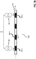
- the electrode structure 100 comprises a nerve cuff 103 that may be constructed using a silicone rubber tube 103, with e.g. centered exposed Pt/Ir, fractal Ir, or similar contacts 104 (three minimum) in its interior wall distributed circumferentially (i.e. along the peripheral direction U), and two annular rings 105.1 and 105.2 placed towards the edge (e.g. arranged on opposing end sections 103b, 103c of the cuff 103) with the latter ring 105.2 proximal to the vagus heart innervation, all in contact with the right vagus nerve 106 surface.
- a nerve cuff 103 may be constructed using a silicone rubber tube 103, with e.g. centered exposed Pt/Ir, fractal Ir, or similar contacts 104 (three minimum) in its interior wall distributed circumferentially (i.e. along the peripheral direction U), and two annular rings 105.1 and 105.2 placed towards the edge (e.g. arranged on opposing end sections 103b,
- Contacts 104.1, 104.2, 104.3 are the stimulating electrodes which are asymmetrically positioned inside the nerve cuff 103a towards the first annular anode 105.1.
- An additional electrode 107 is located outside the nerve cuff 103, its purpose to be described later on.
- the nerve cuff 103 may be self-coiling or it may include other closing mechanisms such as a piano hinge with a nylon suture (not shown).
- Biocompatible strings 108 may be built on the nerve cuff 103 outer wall to open it for easy implantation around the nerve 106.
- rings 105.1, 105.2 may be formed out of individual segmented electrodes in a circumferential arrangement (i.e. along the peripheral direction U) so that when they are driven in synchrony, the electrical field effectively matches that formed by a complete ring electrode.
- the electrode structure 100 is connected to IPG 102, located in the patient's chest area, via a subcutaneously-implanted isolated multi-wire 101 which provides electrical connection to the contacts 104, 107 and rings 105.
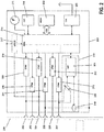
- the IPG 102 in a preferred embodiment of the present invention comprises a case (IPG case) 200 and a header 201 (see also Figure 1 ) for connection of electric conduit 101.
- Header 201 comprises a number of connectors, in the example 202,..., 207, that can electrically connect to connectors of the electrical conduit 101.
- an electric connection between connectors 202,..., 207 and electrodes (contacts, rings, and further electrode) 104, 105, and 107 respectively, of electrode structure 100 can be made.
- one or more stimulation units 208,..., 213 are arranged that are electrically connected to connectors 202,..., 207 respectively, and configured to generate stimulation pulses and to deliver such stimulation pulses via a respective connector 202,...., 207.
- a single stimulation unit and a switch matrix can be provided instead of one stimulation unit for each connector and thus for each electrode 104, 107 and 105.
- delivery of stimulation pulses via selective connectors 202,..., 207 and thus via selected electrodes 104, 107 and 105 can be achieved by the switch matrix.
- all contacts 104 are switched in parallel to each other and thus only one connector and one stimulation unit is needed for them. In the latter embodiment, no selection of contacts 104 for delivery of stimulation pulses is possible.
- the IPG case 200 may participate in the stimulation as a return electrode.
- each stimulation unit 208,..., 213 is connected to and controlled by a control unit 214.
- Control unit 214 controls generation and triggers delivery of stimulation pulses by stimulation units 208,.., 213.
- the stimulation pulses to be generated and triggered by each stimulation unit 208,..., 213 may be tailored for vagus nerve stimulation (VNS), spinal cord stimulation (SCS), or other neurostimulation applications.
- Control unit 214 is further connected to a time signal generator 215 that supplies a time base to control unit 214.
- an activity sensing unit 216 may be provided for sensing movements of the patient via movements of the IPG 102, preferably in three spatial dimensions. This activity sensor would deliver the activity signal to control unit 214.
- Control unit 214 may be further connected to a sub-cutaneous (sECG) sensing unit 217 that is configured to generate a signal representing heart activity.
- a sub-cutaneous (sECG) sensing unit 217 that is configured to generate a signal representing heart activity.
- one input of unit 217 is preferably connected to connector 204 that connects to electrode 107 and the other input to IPG case 200.
- the sECG sensing unit 217 is configured to supply a sECG signal to control unit 214.
- the sECG signal represents the heart activity of a patient. From this signal, inter alia a heart rate of a patient can be determined.
- Control unit 214 may further be connected to an impedance measuring unit 218 that comprises a constant current source 219 for generating and delivering biphasic impedance measuring pulses.
- Current source 219 may electrically connect to IPG case 200 and to at least one of connectors 202,..., 207 and thus to at least one of the electrodes 104, 105 or 107 of nerve cuff electrode 100.
- Impedance measurement unit 218 further comprises a voltage sensing unit 220 that is configured to measure a voltage difference between at least one electrode 104, 105 or 107 of electrode structure 100 and the IPG case 200, or between at least two electrodes 104, 105, or 107, in response to delivery of current pulses by the current source 219.
- Impedance determination unit 221 is configured to generate an impedance signal depending on the voltages measured by voltage sensing unit 220 and to supply such impedance signal to control unit 214.
- the impedance signal generated by impedance measurement unit 218 allows assessing the status of electrodes 104, 105 and 107.
- Control unit 214 may be further connected to a memory unit 222 that may serve to store signals recorded by control unit 214 or programs that control the operation of control unit 214.
- At least a telemetry unit 223 is provided that is also connected to control unit 214.
- Figure 3a shows an embodiment of a guarded-cathode configuration for delivering vagus nerve stimulation (VNS) by IPG 102
- Figure 3b shows the same configuration for the case of spinal cord stimulation (SCS) via an electrode structure 100 implemented using a percutaneous lead 310.
- VNS vagus nerve stimulation
- SCS spinal cord stimulation
- the control unit 214 splits the desired therapy current and injects electrical pulses 300.1, 300.2 (preferably current-based) via rings (i.e. annular anodes) 105.
- the control unit 214 will inject currents 300.1, 300.2 of approximately 1 mA through each ring 105.1, 105.2 so that the current exiting cathode 104.1 equals the desired 2 mA.
- the determination of the difference between the actual currents to flow 300.1 and 300.2 is described below.
- the stimulation is preferably delivered synchronized with cardiac activity for improved therapy outcome and to minimize evoked compound action potential (ECAP) recording contamination by heart activity.
- ECAP recording is preferably performed during the cardiac refractory period.
- sECG may be recorded between the IPG case 200 and any unused electrode on the lead 310.
- ECAPs evoked compound action potentials
- the ECAP will arrive at ring 105.2 typically within 200 ⁇ s.
- stimulation pulse widths for VNS therapy are typically hundreds of ⁇ s long, ECAP recording will overlap with the stimulation pulse itself or it associated balance phase.
- a similar reasoning can be applied to the configuration shown in Figure 3b .
- the sensing front-end 401 is preferably AC-coupled via capacitors 402.1 and 402.2 in a preferred embodiment of the present invention to avoid direct current (DC) leakage, and although these capacitors are of the same nominal value, their actual values may be different given component tolerance. Hence, compensation is required to make the voltages at the inputs of the sensing front-end 401 follow similar voltage transitories during stimulation and balance phases so they can be rejected by the high CMRR of the sensing front-end 401.
- DC direct current
- the ECAP bandwidth of the sensing front-end 401 is typically from tens of Hz to a few kHz.
- capacitors 402 are in the tens of nF range whereas resistors 403.1, 403.2 (nominally equal) are in the hundred kHz range.
- Resistor 404 is in the tens of M ⁇ and permits maintaining the high CMRR of the sensing front-end 401 given tolerances in the components 402, 403.
- capacitors 402.1 and 402.2 are in the tens of pF range and resistors 403.1, 403.2 and 404 implemented via transconductors or other pseudo-resistor techniques.
- Amplifier 401 may utilize a chopper or similar technique for flicker noise reduction.
- compensation of misbalances across the components mentioned and shown in Figure 4 is performed via adjustment of currents 300.1, 300.2 for the stimulation phase (and 405.1, 405.2 for the balance phase accordingly).
- impedance measurements from each ring 105.1, 105.2 to the IPG case 200 are performed. Since the IPG case 200 has much larger area compared to the rings 105.1, 105.2, the impedance measurement ring 105 - IPG case 200 primarily reflects the local impedance seen at each ring 105.1, 105.2.
- the ratio of the resistive part of these impedances is determined and currents 300.1, 300.2 are split such that their ratio corresponds to the inverse ratio of the resistive parts of said impedances and such that the total current that exits cathode 104.1 is met (depolarizing current for therapy).
- the resistive part of the impedance from ring 105.1 and 105.2 to IPG case 200 is 1.9 k ⁇ and 2.0 k ⁇ respectively and both 300.1, 300.2 are to be programmed equal to 1 mA (i.e. 2 mA therapy current is desired).
- the actual current 300.1 will be programmed equal to 1,025 ⁇ A and 300.2 equal to 975 ⁇ A instead.
- auxiliary currents (not shown in Figure 4 for simplicity) may be utilized for compensation. This compensation permits having symmetric or asymmetric balance phases (where currents 405.1 and 405.2 are adjusted accordingly).
- the pulse width is programmed larger than the one used for stimulation resulting in lower balancing currents 405.1, 405.2.
- dummy loads may be utilized to settle the stimulation and balance currents 300 and 405 before switching them to tissue.
- FIG. 5 shows the reduction in resulting stimulation artifact (SA) at the output 406 of the sensing front-end 401 in the case for example of a symmetric balance phase.
- SA stimulation artifact
- Waveform 500 is the SA when stimulation currents 300.1 and 300.2 are both programmed with the desired nominal 1 mA
- 501 is the SA in the case 300.1 is programmed with 975 ⁇ A and 300.2 with 1,025 ⁇ A.
- the residual SA 501 becomes of the same order of magnitude as the evoked compound action potential (ECAP) signal to be recorded. Further methods, as described below, permit extracting a clean ECAP signal of interest.
- ECAP evoked compound action potential
- neurons have a threshold of activation under which they cannot fire an action potential as a result of stimulation. Stimulation with amplitude below this level is referred to as sub-threshold stimulation. Above the amplitude required to activate neurons, stimulation is referred to as supra-threshold.
- the residual SA 501 as shown in Figure 5 is first recorded and digitized (ADC) utilizing a sub-threshold stimulation pulse 300.1, 300.2 and associated balance phase 405.1, 405.2.
- ADC digitized
- sub-threshold pulse is determined to be 1.5 mA through cathode 104.1.
- current 300.1 will be programmed as approximately 769 ⁇ A
- current 300.2 will be programmed as 731 ⁇ A (i.e same difference as for the 2 mA desired therapy).
- the sub-threshold stimulation is expected to generate a very similar SA to the supra-threshold stimulation.
- the desired supra-threshold stimulation pulse (2 mA through cathode 104.1) and balance phase are delivered, the total SA+ECAP signal (block 600, see Figure 6 ) is recorded and subtracted to the sub-threshold one (501) to obtain the desired ECAP 601.
- the time between the sub-threshold and supra-threshold pulses is such that the impedances can be considered invariant.
- a classical forward-masking subtraction method is utilized to isolate the residual SA as shown in Figure 7 .
- This method utilizes two supra-threshold stimulation pulses, i.e. a probe pulse with its associated balance phase 700 and a masker pulse with its associated balance phase 701.
- Probe 700 is delivered first and the SA+ECAP 702 recorded and digitized.
- Masker 701, followed by a probe 703 (identical to probe 700) is delivered next.
- the time between the masker 701 and probe 703 is such that the latter (703) is delivered during the refractory period of the fibers recruited by the former (701).
- the probe 703 only generates a residual SA 704 which is recorded and digitized.
- the digitized signal that contains the residual SA+ECAP 702 is then subtracted from this latter digitized signal 704 that only contains the residual SA to obtain the desired ECAP 601.
- an analog SA simulation circuit is iteratively tuned via feedback through an analog-to-digital converter (ADC) under the control of the implantable pulse generator's (IPG) control unit.
- ADC analog-to-digital converter
- IPG implantable pulse generator's
- the tuning adjusts the analog SA simulator so that it generates waveforms which match the sub-threshold (and later, supra-threshold) SA.
- the output of this analog SA simulation circuit is then subtracted from the received analog signal, resulting in a signal comprised mainly of ECAPs (if stimulation is supra-threshold).
- This embodiment is particular useful for spinal cord stimulation (SCS) therapy delivered to the dorsal columns of the spinal cord through leads connected to an IPG as it is desirable for said IPG to determine the activation level of the dorsal columns in a dynamic way to maintain consistent stimulation.
- SCS spinal cord stimulation
- This adjustment compensates for the dynamic distance between the stimulation electrodes and the dorsal columns during normal patient activity and motion.
- ECAPs evoked compound action potentials
- this alternative embodiment stimulates (by the way of STIM block) via electrodes 800 and senses (by the way of SENSE block) on nearby electrodes 801.
- the IPG's 802 control unit (CTRL) tunes a SA rejection circuit by applying stimulation pulses which may be sub-threshold to the neurons of interest, building an analog cancellation parameter set which is used to control an analog SA simulation circuit 803 which generates an artificial SA matched to the recorded SA from the sensing electrodes 801.
- the analog SA simulation circuit 803 comprises adjustable parameters which model capacitance of electrode-tissue interfaces, tissue resistance, electrochemical reactions, and coupling components in the stimulation and recording circuitry which induce SAs via internal paths.
- the analog SA simulation circuit 803 is able to adjust its artificial SA amplitude and shape to match the amplitude of incoming SAs based on: 1) iterative model tuning and 2) programmed stimulation output amplitude.
- the analog SA simulation circuit 803 may be a group of switchable analog passive components, or a filtered digital-to-analog converter (DAC) which outputs a burst of samples, or a combination thereof.
- DAC digital-to-analog converter
- This artificially produced analog SA 804 is subtracted 805 from the incoming SA signal 806 (generated by a sub-threshold pulse) such that the resulting residual SA is below the amplitude required to resolve the ECAP within the dynamic range of the ADC 807 after amplification 808.
- the resulting residual comprising remaining SA and (if stimulation is supra-threshold) ECAP
Landscapes
- Health & Medical Sciences (AREA)
- Life Sciences & Earth Sciences (AREA)
- Engineering & Computer Science (AREA)
- General Health & Medical Sciences (AREA)
- Biomedical Technology (AREA)
- Veterinary Medicine (AREA)
- Public Health (AREA)
- Animal Behavior & Ethology (AREA)
- Neurology (AREA)
- Heart & Thoracic Surgery (AREA)
- Biophysics (AREA)
- Neurosurgery (AREA)
- Molecular Biology (AREA)
- Physics & Mathematics (AREA)
- Pathology (AREA)
- Medical Informatics (AREA)
- Surgery (AREA)
- Nuclear Medicine, Radiotherapy & Molecular Imaging (AREA)
- Radiology & Medical Imaging (AREA)
- Physiology (AREA)
- Signal Processing (AREA)
- Cardiology (AREA)
- Orthopedic Medicine & Surgery (AREA)
- Artificial Intelligence (AREA)
- Computer Vision & Pattern Recognition (AREA)
- Psychiatry (AREA)
- Electrotherapy Devices (AREA)
Applications Claiming Priority (1)
| Application Number | Priority Date | Filing Date | Title |
|---|---|---|---|
| US201762537003P | 2017-07-26 | 2017-07-26 |
Publications (1)
| Publication Number | Publication Date |
|---|---|
| EP3434321A1 true EP3434321A1 (fr) | 2019-01-30 |
Family
ID=59955415
Family Applications (1)
| Application Number | Title | Priority Date | Filing Date |
|---|---|---|---|
| EP17192554.8A Withdrawn EP3434321A1 (fr) | 2017-07-26 | 2017-09-22 | Stimulation et enregistrement neuronaux, en particulier pour commande en boucle fermée de neuromodulation |
Country Status (2)
| Country | Link |
|---|---|
| US (1) | US10842996B2 (fr) |
| EP (1) | EP3434321A1 (fr) |
Cited By (3)
| Publication number | Priority date | Publication date | Assignee | Title |
|---|---|---|---|---|
| WO2021162794A1 (fr) * | 2020-02-14 | 2021-08-19 | Boston Scientific Neuromodulation Corporation | Systèmes et méthodes d'utilisation de signaux d'électrospinogramme pour une régulation en boucle fermée dans une thérapie de stimulation de la moelle épinière |
| WO2022155032A1 (fr) * | 2021-01-13 | 2022-07-21 | Medtronic, Inc. | Commande ratiométrique pour stimulation électrique |
| WO2025027523A1 (fr) * | 2023-08-01 | 2025-02-06 | Medtronic, Inc. | Optimisation de thérapies de neuromodulation selon les périodes réfractaires cardiaques |
Families Citing this family (34)
| Publication number | Priority date | Publication date | Assignee | Title |
|---|---|---|---|---|
| US9872990B2 (en) | 2011-05-13 | 2018-01-23 | Saluda Medical Pty Limited | Method and apparatus for application of a neural stimulus |
| JP6096759B2 (ja) | 2011-05-13 | 2017-03-15 | サルーダ・メディカル・ピーティーワイ・リミテッド | 神経応答の測定のための方法および装置 |
| WO2012155189A1 (fr) | 2011-05-13 | 2012-11-22 | National Ict Australia Ltd | Méthode et appareil d'estimation du recrutement neuronal-f |
| WO2012155185A1 (fr) | 2011-05-13 | 2012-11-22 | National Ict Australia Ltd | Méthode et appareil de mesure de la réponse neuronale |
| AU2013344311B2 (en) | 2012-11-06 | 2017-11-30 | Saluda Medical Pty Ltd | Method and system for controlling electrical conditions of tissue |
| AU2014351064B2 (en) | 2013-11-15 | 2019-07-04 | Closed Loop Medical Pty Ltd | Monitoring brain neural potentials |
| CA2929874C (fr) | 2013-11-22 | 2023-06-13 | Saluda Medical Pty Ltd | Procede et dispositif de detection d'une reponse neurale dans une mesure neurale |
| WO2015143509A1 (fr) | 2014-03-28 | 2015-10-01 | Saluda Medical Pty Ltd | Évaluation de l'état neuronal à partir de potentiels d'action |
| WO2015168735A1 (fr) | 2014-05-05 | 2015-11-12 | Saluda Medical Pty Ltd | Mesure neuronale amelioree |
| AU2015349614B2 (en) | 2014-11-17 | 2020-10-22 | Saluda Medical Pty Ltd | Method and device for detecting a neural response in neural measurements |
| EP3218046B1 (fr) | 2014-12-11 | 2024-04-17 | Saluda Medical Pty Ltd | Dispositif et programme informatique pour la commande de rétroaction de stimulation neuronale |
| US10588698B2 (en) | 2014-12-11 | 2020-03-17 | Saluda Medical Pty Ltd | Implantable electrode positioning |
| WO2016161484A2 (fr) | 2015-04-09 | 2016-10-13 | Saluda Medical Pty Ltd | Estimation de distance électrode-nerf |
| WO2016191807A1 (fr) | 2015-05-31 | 2016-12-08 | Saluda Medical Pty Ltd | Fixation d'électrode de neurostimulateur cérébral |
| WO2017044904A1 (fr) | 2015-09-11 | 2017-03-16 | Nalu Medical, Inc. | Appareil de stimulation périphérique ou spinale |
| US11191966B2 (en) | 2016-04-05 | 2021-12-07 | Saluda Medical Pty Ltd | Feedback control of neuromodulation |
| EP3474747B1 (fr) | 2016-06-24 | 2026-04-22 | Saluda Medical Pty Ltd | Stimulation neurale pour un artéfact réduit |
| EP4434461A3 (fr) | 2018-04-27 | 2025-03-05 | Saluda Medical Pty Ltd | Neurostimulation de nerfs mixtes |
| CA3117230A1 (fr) * | 2018-10-23 | 2020-04-30 | Saluda Medical Pty Ltd | Procede et dispositif pour stimulation neuronale controlee |
| US11552715B2 (en) * | 2019-06-07 | 2023-01-10 | Korea Advanced Institute Of Science And Technology | Body channel communication method and apparatus for performing the same |
| US20220233125A1 (en) * | 2019-06-07 | 2022-07-28 | The Johns Hopkins University | Intraoperative 'non-lifting' peripheral nerve action potential recording |
| EP4041374A4 (fr) * | 2019-10-04 | 2024-01-24 | Nalu Medical, Inc. | Appareil de stimulation |
| US11260231B2 (en) | 2020-01-24 | 2022-03-01 | Medtronic, Inc. | Electrical stimulation modulation |
| US11491326B2 (en) | 2020-04-30 | 2022-11-08 | Medtronic, Inc. | Stimulation lead with electrodes configured for sensing and stimulation over a partial circumference |
| US11559258B2 (en) | 2020-04-30 | 2023-01-24 | Medtronic, Inc. | Stimulation lead with electrodes configured for sensing and stimulation over a partial circumference |
| US20230337962A1 (en) | 2020-08-28 | 2023-10-26 | Saluda Medical Pty Ltd | Improved Feedback Control of Neurostimulation |
| US20240075286A1 (en) * | 2021-02-24 | 2024-03-07 | Medtronic, Inc. | Electrode selection based on impedance for sensing or stimulation |
| EP4313260A1 (fr) | 2021-03-31 | 2024-02-07 | BIOTRONIK SE & Co. KG | Thérapie de stimulation multi-électrodes de moelle épinière |
| CN113940689B (zh) * | 2021-09-14 | 2023-05-05 | 复旦大学 | 一种闭环深部脑刺激伪迹抑制系统 |
| US12569684B2 (en) | 2021-09-24 | 2026-03-10 | Boston Scientific Neuromodulation Corporation | Calibration of stimulation circuitry in an implantable stimulator device using sensed neural responses to stimulation |
| US20250010077A1 (en) | 2021-11-23 | 2025-01-09 | Biotronik Se & Co. Kg | Stimulation therapy with reduced energy |
| US20250256104A1 (en) * | 2022-04-26 | 2025-08-14 | Nervonik Inc. | Systems and methods for closed loop neuromodulation |
| WO2024002822A1 (fr) | 2022-07-01 | 2024-01-04 | Biotronik Se & Co. Kg | Système et procédé de commande de rétroaction de stimulation neuronale |
| AU2023333902B2 (en) | 2022-08-31 | 2026-03-26 | Boston Scientific Neuromodulation Corporation | Template based artifact reduction in neuromodulation applications |
Citations (7)
| Publication number | Priority date | Publication date | Assignee | Title |
|---|---|---|---|---|
| US20060106441A1 (en) * | 2004-11-15 | 2006-05-18 | Shai Ayal | Techniques for nerve stimulation |
| WO2009090398A2 (fr) * | 2008-01-16 | 2009-07-23 | Cambridge Enterprise Limited | Interface neuronale |
| US20110098796A1 (en) * | 2003-05-23 | 2011-04-28 | Tamir Ben-David | Electrode cuffs |
| US8454529B2 (en) | 2001-04-18 | 2013-06-04 | Cochlear Limited | Minimization of electrical stimulus artifact during measurement of evoked neural response |
| US20130218248A1 (en) * | 2008-09-04 | 2013-08-22 | Boston Scientific Neuromodulation Corporation | Multiple tunable central cathodes on a paddle for increased medial-lateral and rostral-caudal flexibility via current steering |
| US20140039578A1 (en) * | 2002-06-20 | 2014-02-06 | Boston Scientific Neuromodulation Corporation | Implantable microstimulators and methods for unidirectional propagation of action potentials |
| US20150290461A1 (en) * | 2014-04-14 | 2015-10-15 | Xiaoyi Min | Methods and systems for monitoring electrical stimulation using paddle lead |
Family Cites Families (3)
| Publication number | Priority date | Publication date | Assignee | Title |
|---|---|---|---|---|
| US7203548B2 (en) * | 2002-06-20 | 2007-04-10 | Advanced Bionics Corporation | Cavernous nerve stimulation via unidirectional propagation of action potentials |
| US8504161B1 (en) * | 2012-08-07 | 2013-08-06 | Medtronic, Inc. | Modulate vagal signals to reduce inflammation |
| US9895542B2 (en) * | 2015-04-22 | 2018-02-20 | Biotronik Se & Co. Kg | Device and method for selective nerve stimulation |
-
2017
- 2017-09-22 EP EP17192554.8A patent/EP3434321A1/fr not_active Withdrawn
-
2018
- 2018-07-11 US US16/032,701 patent/US10842996B2/en active Active
Patent Citations (7)
| Publication number | Priority date | Publication date | Assignee | Title |
|---|---|---|---|---|
| US8454529B2 (en) | 2001-04-18 | 2013-06-04 | Cochlear Limited | Minimization of electrical stimulus artifact during measurement of evoked neural response |
| US20140039578A1 (en) * | 2002-06-20 | 2014-02-06 | Boston Scientific Neuromodulation Corporation | Implantable microstimulators and methods for unidirectional propagation of action potentials |
| US20110098796A1 (en) * | 2003-05-23 | 2011-04-28 | Tamir Ben-David | Electrode cuffs |
| US20060106441A1 (en) * | 2004-11-15 | 2006-05-18 | Shai Ayal | Techniques for nerve stimulation |
| WO2009090398A2 (fr) * | 2008-01-16 | 2009-07-23 | Cambridge Enterprise Limited | Interface neuronale |
| US20130218248A1 (en) * | 2008-09-04 | 2013-08-22 | Boston Scientific Neuromodulation Corporation | Multiple tunable central cathodes on a paddle for increased medial-lateral and rostral-caudal flexibility via current steering |
| US20150290461A1 (en) * | 2014-04-14 | 2015-10-15 | Xiaoyi Min | Methods and systems for monitoring electrical stimulation using paddle lead |
Non-Patent Citations (3)
| Title |
|---|
| BLUM ET AL.: "Models of Stimulation Artifacts Applied to Integrated Circuit Design", PROCEEDINGS OF THE 26TH ANNUAL INTERNATIONAL CONFERENCE OF THE IEEE EMBS, September 2004 (2004-09-01), pages 4075 - 78 |
| HUGHES M.: "Audio logyOnline", November 2010, article "Funda-mentals of Clinical ECAP Measures in Cochlear Implants: Part 1: Use of the ECAP in Speech Processor Programming (2nd Ed." |
| NAG ET AL.: "Sensing of Stimulus Artifact Suppressed Signals from Electrode Interfaces", IEEE SENSORS JOURNAL, vol. 15, no. 7, July 2015 (2015-07-01), pages 3734 - 42, XP011581162, DOI: doi:10.1109/JSEN.2015.2399248 |
Cited By (4)
| Publication number | Priority date | Publication date | Assignee | Title |
|---|---|---|---|---|
| WO2021162794A1 (fr) * | 2020-02-14 | 2021-08-19 | Boston Scientific Neuromodulation Corporation | Systèmes et méthodes d'utilisation de signaux d'électrospinogramme pour une régulation en boucle fermée dans une thérapie de stimulation de la moelle épinière |
| US11998743B2 (en) | 2020-02-14 | 2024-06-04 | Boston Scientific Neuromodulation Corporation | Systems and methods for using electrospinogram signals for closed loop control in Spinal Cord Stimulation therapy |
| WO2022155032A1 (fr) * | 2021-01-13 | 2022-07-21 | Medtronic, Inc. | Commande ratiométrique pour stimulation électrique |
| WO2025027523A1 (fr) * | 2023-08-01 | 2025-02-06 | Medtronic, Inc. | Optimisation de thérapies de neuromodulation selon les périodes réfractaires cardiaques |
Also Published As
| Publication number | Publication date |
|---|---|
| US10842996B2 (en) | 2020-11-24 |
| US20190030339A1 (en) | 2019-01-31 |
Similar Documents
| Publication | Publication Date | Title |
|---|---|---|
| US10842996B2 (en) | Neural stimulation and recording, particularly for neuromodulation closed-loop control | |
| US12433528B2 (en) | Neural stimulation for reduced artefact | |
| US20250295340A1 (en) | Method and apparatus for estimating neural recruitment | |
| CN113226449B (zh) | 用于受控神经刺激的方法和设备 | |
| US10183168B2 (en) | Systems and methods for automated charge balancing of multiple electrodes for uninterrupted therapy and evoked response sensing | |
| EP3870275B1 (fr) | Minimisation d'artefact de neurostimulation | |
| US7171261B1 (en) | Forward masking method for estimating neural response | |
| US20240033522A1 (en) | Intra-Stimulus Recruitment Control | |
| US20230200738A1 (en) | Neural Recording with Stimulus Crosstalk Compensation | |
| US20240189599A1 (en) | Methods and Apparatus for Improved Measurement of Compound Action Potentials | |
| US7283877B1 (en) | Method of measuring neural responses | |
| Butz | Design and implementation of cause-based and consequence-based control circuits for active charge balancing in CMOS integrated neural stimulator | |
| US20250331763A1 (en) | Methods and systems for measuring evoked neural responses | |
| WO2025039032A1 (fr) | Mesure améliorée de réponses évoquées à une stimulation neuronale |
Legal Events
| Date | Code | Title | Description |
|---|---|---|---|
| PUAI | Public reference made under article 153(3) epc to a published international application that has entered the european phase |
Free format text: ORIGINAL CODE: 0009012 |
|
| AK | Designated contracting states |
Kind code of ref document: A1 Designated state(s): AL AT BE BG CH CY CZ DE DK EE ES FI FR GB GR HR HU IE IS IT LI LT LU LV MC MK MT NL NO PL PT RO RS SE SI SK SM TR |
|
| AX | Request for extension of the european patent |
Extension state: BA ME |
|
| STAA | Information on the status of an ep patent application or granted ep patent |
Free format text: STATUS: THE APPLICATION IS DEEMED TO BE WITHDRAWN |
|
| 18D | Application deemed to be withdrawn |
Effective date: 20190731 |