EP3434972A1 - Deckel für einen einseitig nach oben offenen hohlkörper - Google Patents
Deckel für einen einseitig nach oben offenen hohlkörper Download PDFInfo
- Publication number
- EP3434972A1 EP3434972A1 EP18181492.2A EP18181492A EP3434972A1 EP 3434972 A1 EP3434972 A1 EP 3434972A1 EP 18181492 A EP18181492 A EP 18181492A EP 3434972 A1 EP3434972 A1 EP 3434972A1
- Authority
- EP
- European Patent Office
- Prior art keywords
- lid
- slot
- jacket
- hollow body
- horizontal plane
- Prior art date
- Legal status (The legal status is an assumption and is not a legal conclusion. Google has not performed a legal analysis and makes no representation as to the accuracy of the status listed.)
- Granted
Links
Images

Classifications
-
- F—MECHANICAL ENGINEERING; LIGHTING; HEATING; WEAPONS; BLASTING
- F21—LIGHTING
- F21V—FUNCTIONAL FEATURES OR DETAILS OF LIGHTING DEVICES OR SYSTEMS THEREOF; STRUCTURAL COMBINATIONS OF LIGHTING DEVICES WITH OTHER ARTICLES, NOT OTHERWISE PROVIDED FOR
- F21V37/00—Details of lighting devices employing combustion as light source, not otherwise provided for
- F21V37/02—Special adaptation for protection against draughts ; Draft controllers
-
- F—MECHANICAL ENGINEERING; LIGHTING; HEATING; WEAPONS; BLASTING
- F21—LIGHTING
- F21L—LIGHTING DEVICES OR SYSTEMS THEREOF, BEING PORTABLE OR SPECIALLY ADAPTED FOR TRANSPORTATION
- F21L19/00—Lanterns, e.g. hurricane lamps or candle lamps
-
- F—MECHANICAL ENGINEERING; LIGHTING; HEATING; WEAPONS; BLASTING
- F21—LIGHTING
- F21V—FUNCTIONAL FEATURES OR DETAILS OF LIGHTING DEVICES OR SYSTEMS THEREOF; STRUCTURAL COMBINATIONS OF LIGHTING DEVICES WITH OTHER ARTICLES, NOT OTHERWISE PROVIDED FOR
- F21V35/00—Candle holders
Definitions
- the invention relates to a lid for a hollow body which is open on one side and in which a candle is arranged, in particular a lid for a grave light.
- Grave lights usually consist of a cup (may be made of different materials) filled with fuel mass (usually mineral or organic waxes) and having a centered wick. For weather protection and optical reasons usually a lid (often made of metal or plastic) is placed on top. Grave lights are usually fired outdoors and are fully exposed to the elements.
- lids for one-sided upwardly open hollow body in which a candle is arranged, wherein the lid is a downwardly open hollow body and can be plugged or screwed onto the upwardly open hollow body, wherein the jacket of the lid in attached state the shell of the upwardly open hollow body projects beyond the top, wherein the jacket of the lid is provided with openings.
- the openings are designed as vertically extending openings which are formed by openings in the shell of the lid, for example by punching circular surfaces.
- the disadvantage is that through such openings precipitate can easily penetrate, which is then derive between the lid and the one-sided upwardly open hollow body.
- the one-sided open hollow body is usually equipped with an upwardly tapering upper end, so that through the lid penetrating water between the lid and the tapered end portion is derived.
- the object underlying the invention is to provide a cover which is better protected against the ingress of precipitate.
- At least one opening is formed by the jacket of the cover having a slot between two points lying on a horizontal plane and that the material of the jacket being formed below the slot into the interior of the hollow body of the cover, so that a substantially horizontally extending opening extends between the upper edge formed by the slot and the lower edge formed by the slot.
- the cover may preferably be made of plastic or more preferably of metal.
- the lid has side openings which are constructed so that a part of the side wall or skirt inclines inwardly only along a horizontal slot and thus the resulting opening faces up and overlaps the lid top.
- rainwater runoff on the lid can not penetrate into the interior of the lid since it drips off at the upper edge of the horizontal slot and is discharged from the sidewall to the outside.
- wind can make direct impact on the flame, as it is deflected and attenuated by the sidewall.
- the openings are mounted in different numbers on the side wall of the lid around at lateral intervals and preferably in two rows. Due to the openings thus arranged, mainly exhaust air from the candle flame exits through the upper row, and through the lower row mainly supply air into the light interior. Thus, the controlled burn of the light is ensured.
- a lid is proposed according to claim 11 for solving the problem.
- this variant is less preferred, because the resulting outwardly projecting Ausdellungen are disadvantageous in handling and packaging.
- the cover 1 has an upper cover surface 2 and a jacket 3 which extends downwards from the edge of the cover surface 2, so that the cover 1 is a hollow body open on one side, as shown, preferably in the form of a hollow cylinder, ie with a circular shape Top surface 2.
- This mold is particularly easy to manufacture and easy to handle.
- the hollow body can also be present as a prism with a polygon, an oval or an ellipse as a base.
- the lid 1 could taper upwards and be present as a hollow cone or hollow truncated cone or hollow pyramid or hollow truncated pyramid.
- an upwardly widening cover 1 is conceivable.
- the jacket 3 of the cover 1 has indentations 4, at the upper end of which there is an approximately horizontally extending opening.
- the cover 1 preferably has vertically extending grooves 7, which provide a way for the water flowing out between the webs 5.
- the grooves 7 can be made by embossing. Seen in the vertical direction, the webs 5 are located above the indentations 4 and thus over the approximately horizontally extending openings, with a web 5 preferably extending over the entire length of a horizontally extending opening. Preferably, the webs 5 seen in the circumferential direction are slightly longer than the openings.
- the top surface 2 is preferably formed rising to its center, so that can collect on this no water. As shown, the top surface 2 may be formed by one or more annular regions, one or more hollow frusto-conical regions, and a raised central circular region 8.
- At the lower end of the edge of the shell 3 may be formed widened, for example, by the material is folded upwards and outwards or rolled as a bead 6 is present.
- the stability of the lid 1 is increased and avoided a sharp edge, which facilitates placement of the lid 1 on the one-sided upwardly open hollow body and avoids injuries, in particular to lids 1 made of metal.
- the openings are formed by the fact that the shell 3 has a slot between each two lying on a horizontal plane points and that the material of the shell 3 is formed below the slot into the interior of the hollow body of the lid 1, so that between the formed by the slot upper edge 9 and the bottom edge formed by the slot 10 extends a substantially horizontally extending opening.
- the upper edge 9 is preferably horizontal.
- the upper edges 9 of successive openings of a peripheral region of the shell 3 are preferably on one level.
- the lower edge 10 extends along an arc from one of the two lying on a horizontal plane points of the slot starting from the jacket 3 first toward the interior of the lid 1 and then out again in the direction of the jacket 3 to the second of the two on a horizontal plane lying points of the slot.
- the lower edge 10 of each slot extends along an arc from one of the two points of the slot lying on a horizontal plane, starting first sloping and then rising again to the second of the two on a horizontal plane lying points of the slot.
- Fig. 3 Therefore, a gap between the two edges 9, 10 visible.
- the lower edge 10 is the upper edge of the indentation 4, the indentation 4 preferably merges along the arcuate path of its lower edge 11 into the jacket 3, which first descends from one of the two points of the slot lying on a horizontal plane and then again rising to the second of the two lying on a horizontal plane points of the slot and wherein the indentation 4 is inclined starting from its lower edge 11 relative to the casing 3 into the interior of the lid 1.
- the lid 1 preferably has six openings according to the invention, which lie along a peripheral region of the jacket 3.
- more or less such openings are also conceivable, for example four or eight.
- At least four, in particular at least six openings per row are preferably present. With an even number of openings per row, these are preferably diametrically opposite each other.
- the second row is preferably identical to the first row and arranged in phase with this.
- the material of the lid 1 is preferably metal, for example steel or aluminum, alternatively it may be formed of heat-resistant plastic.
- a hollow cylinder open on one side is preferably used as the starting base for producing, which is provided with slots by punching or cutting and is provided with the indentations 4 by plastic deformation.
- the webs 5 and grooves 7, as well as the survey of the top surface 2 can also be formed by plastic deformation, such as embossing. It becomes advantageous in a first step embossed the top surface 2 together with webs 5 and only then the indentations 4 and 7 grooves formed.
- Fig. 3 the attachment of the cover 1 is illustrated on the hollow body of a grave light.
- the upwardly one-sided open hollow body no special requirements are made, since the by embossing inside protruding grooves 7 and / or the depressions 4 form a stop for the edge of the upwardly open on one side hollow body, so that they cover 1 in fix the intended position.
- the upwardly open on one side hollow body can thus preferably be present as a hollow body whose outer circumference is slightly less than the inner diameter of the shell 3, or precisely fitting this.
- the upwardly one-sided open hollow body does not need to have upwardly tapering area and no stop for the cover 1, so it is very inexpensive to produce.
- At least one opening could also be formed by the shell 3 having a slot between two points lying on a horizontal plane and the material of the shell 3 being formed above the slot outwardly by the hollow body of the cover 1, so that extending between the upper edge 9 formed by the slot and the lower edge 10 formed by the slot has a substantially horizontally extending opening.
- the lower edge 10 is horizontal.
- the upper edge 9 then extends along an arc from one of the two lying on a horizontal plane points of the slot starting first rising and then descending again to the second of the two lying on a horizontal plane points of the slot.
- the upper edge 9 is the lower edge of a Ausdellung, wherein the Ausdellung goes along the arc of its upper edge in the shell 3, which starting from one of the two lying on a horizontal plane points of the slot first rising and then sloping back to second of the two lying on a horizontal plane points of the slot and wherein the Ausdellung starting from their upper edge opposite the jacket 3 of the lid 1 is inclined outwards.
- An opening formed in accordance with this less preferred variant may be provided instead of one of the openings shown in the figures. All openings of this less preferred variant can be designed accordingly. There may be openings of this less preferred variant in combination with openings of the preferred variant on a cover 1. On a horizontal slot also a dent 4 according to the preferred variant and a Ausdellung according to the less preferred variant may be present together.
Landscapes
- Engineering & Computer Science (AREA)
- General Engineering & Computer Science (AREA)
- Chemical & Material Sciences (AREA)
- Combustion & Propulsion (AREA)
- Closures For Containers (AREA)
Abstract
Description
- Die Erfindung betrifft einen Deckel für einen einseitig nach oben offenen Hohlkörper, in dem eine Kerze angeordnet ist, insbesondere einen Deckel für ein Grablicht.
- Grablichter bestehen üblicherweise aus einem Becher (kann aus unterschiedlichen Materialien bestehen) der mit Brennmasse gefüllt ist (üblicherweise mineralische oder organische Wachse) und einen zentriert angebrachten Docht aufweist. Gegen Witterungsschutz und aus optischen Gründen wird üblicherweise ein Deckel (oft aus Metall oder Kunststoff) oben aufgesetzt. Grablichter werden üblicherweise im Freien gebrannt und sind der Witterung voll ausgesetzt.
- Nach dem Stand der Technik sind Deckel für einseitig nach oben offene Hohlkörper bekannt, in denen eine Kerze angeordnet ist, wobei der Deckel ein nach unten offener Hohlkörper ist und auf den nach oben offenen Hohlkörper aufgesteckt oder aufgeschraubt werden kann, wobei der Mantel des Deckels im angebrachten Zustand den Mantel des nach oben offenen Hohlkörpers nach oben hin überragt, wobei der Mantel des Deckels mit Öffnungen versehen ist. Die Öffnungen sind dabei als vertikal verlaufende Öffnungen ausgeführt, welche durch Öffnungen im Mantel des Deckels gebildet sind, beispielsweise durch das Ausstanzen von Kreisflächen. Nachteilig ist, dass durch solche Öffnungen Niederschlag leicht eindringen kann, welcher dann zwischen Deckel und dem einseitig nach oben offenen Hohlkörper abzuleiten ist. Dazu ist der einseitig offene Hohlkörper meist mit einem sich nach oben verjüngenden oberen Endbereich ausgestattet, sodass durch den Deckel eindringendes Wasser zwischen Deckel und dem sich verjüngenden Endbereich abgeleitet wird.
- Die der Erfindung zu Grunde liegende Aufgabe besteht darin, einen Deckel bereit zu stellen, welcher besser gegen das Eindringen von Niederschlag geschützt ist.
- Für das Lösen der Aufgabe wird vorgeschlagen, dass zumindest eine Öffnung dadurch gebildet ist, dass der Mantel des Deckels zwischen zwei auf einer horizontalen Ebene liegenden Punkten einen Schlitz aufweist und dass das Material des Mantels unterhalb des Schlitzes ins Innere des Hohlkörpers des Deckels eingeformt ist, sodass sich zwischen der durch den Schlitz gebildeten oberen Kante und der durch den Schlitz gebildeten unteren Kante eine im Wesentlichen horizontal verlaufende Öffnung erstreckt.
- Der Deckel kann bevorzugt aus Kunststoff oder besonders bevorzugt aus Metall gebildet sein. Der Deckel weist seitliche Öffnungen auf, die so konstruiert sind, dass sich ein Teil der Seitenwand bzw. des Mantels nur entlang eines horizontalen Schlitzes nach innen neigt und somit die sich ergebende Öffnung nach oben zeigt und vom Deckeloberteil überlappt wird. Somit kann am Deckel abrinnendes Regenwasser nicht in den Innenraum des Deckels eindringen, da es an der oberen Kante des horizontalen Schlitzes abtropft und von der Seitenwand nach außen abgeleitet wird. Da die Öffnungen nach oben zeigen, kann Wind erschwert direkt auf die Flamme treffen, da er von der Seitenwand abgelenkt und abgeschwächt wird. Die Öffnungen sind in unterschiedlicher Anzahl an der Seitenwand des Deckels rundherum in seitlichen Abständen und bevorzugt in zwei Reihen angebracht. Durch die so angebrachten Öffnungen tritt durch die obere Reihe hauptsächlich Abluft der Kerzenflamme aus, und durch die untere Reihe hauptsächlich Zuluft in den Lichtinnenraum ein. Somit wird der geregelte Abbrand des Lichtes sichergestellt.
- Weniger bevorzugt wird für das Lösen der Aufgabe ein Deckel gemäß Anspruch 11 vorgeschlagen. Unter anderem ist diese Variante weniger bevorzugt, weil die resultierenden nach außen abstehenden Ausdellungen bei der Handhabung und Verpackung nachteilig sind.
- Eine bevorzugte Ausführungsvariante des erfindungsgemäßen Deckels wird an Hand von Zeichnungen veranschaulicht:
- Fig. 1:
- Zeigt den bevorzugten erfindungsgemäßen Deckel in perspektivischer Ansicht von schräg oben.
- Fig. 2:
- Zeigt den bevorzugten erfindungsgemäßen Deckel in perspektivischer Ansicht von schräg unten.
- Fig. 3:
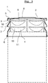
- Zeigt den bevorzugten erfindungsgemäßen Deckel in seitlicher Schnittansicht mit strichliert veranschaulichtem Hohlkörper eines Grablichts.
- Wie in den
Fig. 1-3 veranschaulicht ist, weist der Deckel 1 eine obere Deckfläche 2 und einen Mantel 3 auf, welcher sich vom Rand der Deckfläche 2 nach unten hin erstreckt, sodass der Deckel 1 ein einseitig offener Hohlkörper ist, wie dargestellt bevorzugt in Form eines Hohlzylinders, also mit kreisförmiger Deckfläche 2. Diese Form ist besonders einfach in der Herstellung und gut zu handhaben. Weniger bevorzugt kann der Hohlkörper auch als Prisma mit einem Polygon, einem Oval oder einer Ellipse als Grundfläche vorliegen. Zudem könnte sich der Deckel 1 nach oben hin verjüngen und als hohler Kegel oder hohler Kegelstumpf oder hohle Pyramide oder hohler Pyramidenstumpf vorliegen. Außerdem ist auch ein sich nach oben verbreiternder Deckel 1 denkbar. - Der Mantel 3 des Deckels 1 weist Eindellungen 4 auf, an deren oberen Ende jeweils eine in etwa horizontal verlaufende Öffnung vorliegt.
- Am Rand der Deckfläche 2 sind bevorzugt Stege 5 angeordnet, welche sich aus der Deckfläche 2 nach oben erheben und welche im Bereich der Eindellungen 4 vorliegen, sodass von der Deckfläche 2 abfließendes Wasser nicht über die Eindellungen 4 abfließt, sondern in den Bereichen zwischen jeweils aufeinanderfolgenden Eindellungen 4. In den Bereichen zwischen den Eindellungen 4 weist der Deckel 1 bevorzugt vertikal verlaufende Rinnen 7 auf, welche einen Weg für das zwischen den Stegen 5 abfließende Wasser vorgeben. Die Rinnen 7 können durch Prägung hergestellt werden. Die Stege 5 liegen in vertikaler Richtung gesehen über den Eindellungen 4 und somit über den in etwa horizontal verlaufenden Öffnungen, wobei sich bevorzugt jeweils ein Steg 5 über die gesamte Länge einer horizontal verlaufenden Öffnung erstreckt. Bevorzugt sind die Stege 5 in Umfangsrichtung gesehen etwas länger als die Öffnungen.
- Die Deckfläche 2 ist bevorzugt zu ihrem Zentrum hin ansteigend ausgebildet, damit sich auf dieser kein Wasser sammeln kann. Wie dargestellt kann die Deckfläche 2 durch einen oder mehrere ringförmige Bereiche, einen oder mehrere hohlkegelstumpfförmige Bereiche und einen erhöhten zentralen kreisförmigen Bereich 8 gebildet sein.
- Am unteren Ende kann der Rand des Mantels 3 verbreitert ausgebildet sein, beispielsweise indem dessen Material nach oben und außen gefaltet oder gerollt als Wulst 6 vorliegt. Dadurch wird die Stabilität des Deckels 1 erhöht und eine scharfe Kante vermieden, was ein Aufsetzen des Deckels 1 auf den einseitig nach oben offenen Hohlkörper erleichtert und Verletzungen insbesondere an Deckeln 1 aus Metall vermeidet.
- Wie in den
Fig. 1-3 zu erkennen ist, sind die Öffnungen dadurch gebildet, dass der Mantel 3 zwischen jeweils zwei auf einer horizontalen Ebene liegenden Punkten einen Schlitz aufweist und dass das Material des Mantels 3 unterhalb des Schlitzes ins Innere des Hohlkörpers des Deckels 1 eingeformt ist, sodass sich zwischen der durch den Schlitz gebildeten oberen Kante 9 und der durch den Schlitz gebildeten unteren Kante 10 eine im Wesentlichen horizontal verlaufende Öffnung erstreckt. Wie dargestellt verläuft die obere Kante 9 bevorzugt horizontal. Die oberen Kanten 9 aufeinanderfolgender Öffnungen eines Umfangsbereichs des Mantels 3 liegen bevorzugt auf einer Ebene. - Die untere Kante 10 verläuft entlang eines Bogens von einem der beiden auf einer horizontalen Ebene liegenden Punkte des Schlitzes ausgehend weg vom Mantel 3 zuerst in Richtung des Inneren des Deckels 1 und dann wieder heraus in Richtung des Mantels 3 zum zweiten der beiden auf einer horizontalen Ebene liegenden Punkte des Schlitzes.
- Bevorzugt verläuft die unter Kante 10 jedes Schlitzes entlang eines Bogens von einem der beiden auf einer horizontalen Ebene liegenden Punkte des Schlitzes ausgehend zuerst abfallend und dann wieder ansteigend zum zweiten der beiden auf einer horizontalen Ebene liegenden Punkte des Schlitzes. In
Fig. 3 ist daher ein Spalt zwischen den beiden Kanten 9, 10 sichtbar. - Die untere Kante 10 ist die obere Kante der Eindellung 4, wobei die Eindellung 4 bevorzugt entlang der Bogenbahn ihrer unteren Kante 11 in den Mantel 3 über geht, welche ausgehend von einem der beiden auf einer horizontalen Ebene liegenden Punkte des Schlitzes zuerst abfallend und dann wieder ansteigend zum zweiten der beiden auf einer horizontalen Ebene liegenden Punkte des Schlitzes verläuft und wobei die Eindellung 4 ausgehend von ihrer unteren Kante 11 gegenüber dem Mantel 3 ins Innere des Deckels 1 geneigt ist.
- Wie dargestellt weist der Deckel 1 vorzugsweise sechs erfindungsgemäße Öffnungen auf, die entlang eines Umfangsbereichs des Mantels 3 liegen. Denkbar sind aber auch mehr oder weniger solche Öffnungen, beispielsweise vier oder acht. Bevorzugt sind zumindest vier, insbesondere zumindest 6 Öffnungen je Reihe vorhanden. Bei einer geraden Anzahl von Öffnungen je Reihe liegen sich diese bevorzugt jeweils diametral gegenüber.
- Bevorzugt ist eine zweite Reihe von Öffnungen vorhanden, die vertikal beabstandet zur ersten Reihe vorliegt. Auch mehr als zwei Reihen sind denkbar, wobei zwei Reihen aufgrund der eingangs beschriebenen Luftzirkulation als technisch vorteilhaft angesehen werden. Die zweite Reihe ist bevorzugt ident zur ersten Reihe ausgeführt und phasengleich zu dieser angeordnet.
- Das Material des Deckels 1 ist bevorzugt Metall, beispielsweise Stahl oder Aluminium, alternativ kann er aus hitzebeständigem Kunststoff gebildet sein.
- Bei einer Ausführung aus Metall wird zur Herstellung vorzugsweise als Ausgangsbasis ein einseitig offener Hohlzylinder verwendet, welcher durch Stanzen oder Schneiden mit Schlitzen versehen wird und durch plastische Verformung mit den Eindellungen 4 versehen wird. Die Stege 5 und Rinnen 7, sowie die Erhebung der Deckfläche 2 können ebenfalls durch plastische Verformung, beispielsweise Prägen gebildet werden. Vorteilhaft wird in einem ersten Schritt die Deckfläche 2 samt Stege 5 geprägt und erst nachfolgend die Eindellungen 4 und Rinnen 7 geformt.
- In
Fig. 3 ist das Anbringen des Deckels 1 am Hohlkörper eines Grablichts veranschaulicht. An den nach oben hin einseitig offenen Hohlkörper sind dabei keine speziellen Anforderungen gestellt, da die durchs Prägen nach Innen vorstehenden Rinnen 7 und/oder die Eindellungen 4 einen Anschlag für den Rand des nach oben hin einseitig offenen Hohlkörpers bilden, sodass diese den Deckel 1 in der vorgesehenen Position fixieren. Der nach oben hin einseitig offene Hohlkörper kann somit bevorzugt als Hohlkörper vorliegen, dessen Außenumfang etwas geringer als der Innendurchmesser des Mantels 3, oder passgenau zu diesem vorliegt. Der nach oben hin einseitig offene Hohlkörper braucht keinen sich nach oben hin verjüngenden Bereich und keinen Anschlag für den Deckel 1 aufzuweisen, ist also sehr kostengünstig herstellbar. - In einer weniger bevorzugten Ausführungsvariante könnte zumindest eine Öffnung auch dadurch gebildet sein, dass der Mantel 3 zwischen zwei auf einer horizontalen Ebene liegenden Punkten einen Schlitz aufweist und dass das Material des Mantels 3 oberhalb des Schlitzes nach außen vom Hohlkörper des Deckels 1 ausgeformt ist, sodass sich zwischen der durch den Schlitz gebildeten oberen Kante 9 und der durch den Schlitz gebildeten unteren Kante 10 eine im Wesentlichen horizontal verlaufende Öffnung erstreckt. Bevorzugt verläuft dann die untere Kante 10 horizontal. Bevorzugt verläuft dann die obere Kante 9 entlang eines Bogens von einem der beiden auf einer horizontalen Ebene liegenden Punkte des Schlitzes ausgehend zuerst ansteigend und dann wieder absteigend zum zweiten der beiden auf einer horizontalen Ebene liegenden Punkte des Schlitzes. Bevorzugt ist dann die obere Kante 9 die untere Kante einer Ausdellung, wobei die Ausdellung entlang der Bogenbahn ihrer oberen Kante in den Mantel 3 über geht, welche ausgehend von einem der beiden auf einer horizontalen Ebene liegenden Punkte des Schlitzes zuerst ansteigend und dann wieder abfallend zum zweiten der beiden auf einer horizontalen Ebene liegenden Punkte des Schlitzes verläuft und wobei die Ausdellung ausgehend von ihrer oberen Kante gegenüber dem Mantel 3 des Deckels 1 nach außen geneigt ist. Eine gemäß dieser weniger bevorzugten Variante gebildete Öffnungen kann anstelle einer der in den Figuren abgebildeten Öffnungen vorgesehen sein. Es können alle Öffnungen dieser weniger bevorzugten Variante entsprechend ausgeführt sein. Es können Öffnungen dieser weniger bevorzugten Variante in Kombination mit Öffnungen der bevorzugten Variante an einem Deckel 1 vorhanden sein. An einem horizontalen Schlitz können auch eine Eindellung 4 gemäß der bevorzugten Variante und eine Ausdellung gemäß der weniger bevorzugten Variante gemeinsam vorliegen.
Claims (14)
- Deckel (1) für einen einseitig nach oben offenen Hohlkörper, in dem eine Kerze angeordnet ist, wobei der Deckel (1) ein nach unten offener Hohlkörper ist und auf den nach oben offenen Hohlkörper aufgesteckt oder aufgeschraubt werden kann, wobei der Mantel (3) des Deckels (1) im angebrachten Zustand den Mantel des nach oben offenen Hohlkörpers nach oben hin überragt, wobei der Mantel (3) des Deckels (1) mit Öffnungen versehen ist,
dadurch gekennzeichnet, dass
zumindest eine Öffnung dadurch gebildet ist, dass der Mantel (3) zwischen zwei auf einer horizontalen Ebene liegenden Punkten einen Schlitz aufweist und dass das Material des Mantels (3) unterhalb des Schlitzes ins Innere des Hohlkörpers des Deckels (1) eingeformt ist, sodass sich zwischen der durch den Schlitz gebildeten oberen Kante (9) und der durch den Schlitz gebildeten unteren Kante (10) eine im Wesentlichen horizontal verlaufende Öffnung erstreckt. - Deckel (1) nach Anspruch 1, dadurch gekennzeichnet, dass die obere Kante (9) horizontal verläuft.
- Deckel (1) nach einem der Ansprüche 1 bis 2, dadurch gekennzeichnet, dass die unter Kante (10) entlang eines Bogens von einem der beiden auf einer horizontalen Ebene liegenden Punkte des Schlitzes ausgehend zuerst abfallend und dann wieder ansteigend zum zweiten der beiden auf einer horizontalen Ebene liegenden Punkte des Schlitzes verläuft.
- Deckel (1) nach einem der Ansprüche 1 bis 3, dadurch gekennzeichnet, dass die unter Kante (10) die obere Kante einer Eindellung (4) ist, wobei die Eindellung (4) entlang der Bogenbahn ihrer unteren Kante (11) in den Mantel (3) über geht, welche ausgehend von einem der beiden auf einer horizontalen Ebene liegenden Punkte des Schlitzes zuerst abfallend und dann wieder ansteigend zum zweiten der beiden auf einer horizontalen Ebene liegenden Punkte des Schlitzes verläuft und wobei die Eindellung (4) ausgehend von ihrer unteren Kante (11) gegenüber dem Mantel (3) ins Innere des Deckels (1) geneigt ist.
- Deckel (1) nach einem der Ansprüche 1 bis 4, dadurch gekennzeichnet, dass zumindest vier, vorzugsweise zumindest sechs erfindungsgemäße Öffnungen entlang eines Umfangsbereichs des Mantels (3) liegen.
- Deckel (1) nach Anspruch 5, dadurch gekennzeichnet, dass weitere zumindest vier, vorzugsweise zumindest sechs erfindungsgemäße Öffnungen entlang eines weiteren Umfangsbereichs des Mantels (3) liegen, wobei die beiden Umfangsbereiche vertikal zueinander beabstandet sind.
- Deckel (1) nach einem der Ansprüche 5 bis 6, dadurch gekennzeichnet, dass im Bereich zwischen zwei jeweils in Umfangsrichtung aneinander anschließenden Öffnungen eine vertikale Rinne (7) im Mantel (3) verläuft.
- Deckel (1) nach einem der Ansprüche 1 bis 7, dadurch gekennzeichnet, dass der Rand der Deckfläche (2) des Deckels (1) mit erhabenen Stegen (5) versehen ist, wobei zwischen zwei jeweils in Umfangsrichtung aneinander anschließenden Stegen (5) Abläufe definiert sind, sodass durch diese Wasser von der Deckfläche (2) abfließen kann.
- Deckel (1) nach Anspruch 8, dadurch gekennzeichnet, dass die Stege (5) in vertikaler Richtung gesehen über erfindungsgemäßen Öffnungen liegen und jeweils ein Steg (5) über die gesamte Länge einer erfindungsgemäßen Öffnung verläuft.
- Deckel (1) nach einem der Ansprüche 1 bis 9, dadurch gekennzeichnet, dass dieser ein einseitig offener Hohlzylinder ist.
- Deckel (1) für einen einseitig nach oben offenen Hohlkörper, in dem eine Kerze angeordnet ist, wobei der Deckel (1) ein nach unten offener Hohlkörper ist und auf den nach oben offenen Hohlkörper aufgesteckt oder aufgeschraubt werden kann, wobei der Mantel (3) des Deckels (1) im angebrachten Zustand den Mantel des nach oben offenen Hohlkörpers nach oben hin überragt, wobei der Mantel (3) des Deckels (1) mit Öffnungen versehen ist,
dadurch gekennzeichnet, dass
zumindest eine Öffnung dadurch gebildet ist, dass der Mantel (3) zwischen zwei auf einer horizontalen Ebene liegenden Punkten einen Schlitz aufweist und dass das Material des Mantels (3) oberhalb des Schlitzes nach außen vom Hohlkörper des Deckels (1) ausgeformt ist, sodass sich zwischen der durch den Schlitz gebildeten oberen Kante (9) und der durch den Schlitz gebildeten unteren Kante (10) eine im Wesentlichen horizontal verlaufende Öffnung erstreckt. - Deckel (1) nach Anspruch 11, dadurch gekennzeichnet, dass die untere Kante (10) horizontal verläuft.
- Deckel (1) nach einem der Ansprüche 11 bis 12, dadurch gekennzeichnet, dass die obere Kante (9) entlang eines Bogens von einem der beiden auf einer horizontalen Ebene liegenden Punkte des Schlitzes ausgehend zuerst ansteigend und dann wieder abfallend zum zweiten der beiden auf einer horizontalen Ebene liegenden Punkte des Schlitzes verläuft.
- Deckel (1) nach einem der Ansprüche 11 bis 13, dadurch gekennzeichnet, dass die obere Kante (9) die untere Kante einer Ausdellung ist, wobei die Ausdellung entlang der Bogenbahn ihrer oberen Kante in den Mantel (3) über geht, welche ausgehend von einem der beiden auf einer horizontalen Ebene liegenden Punkte des Schlitzes zuerst ansteigend und dann wieder abfallend zum zweiten der beiden auf einer horizontalen Ebene liegenden Punkte des Schlitzes verläuft und wobei die Ausdellung ausgehend von ihrer oberen Kante gegenüber dem Mantel (3) des Deckels (1) nach außen geneigt ist.
Priority Applications (2)
| Application Number | Priority Date | Filing Date | Title |
|---|---|---|---|
| SI201830048T SI3434972T1 (sl) | 2017-07-06 | 2018-07-03 | Pokrov za enostransko, navzgor odprto votlo telo |
| PL18181492T PL3434972T3 (pl) | 2017-07-06 | 2018-07-03 | Pokrywka pustego korpusu otwartego z jednej strony od góry |
Applications Claiming Priority (1)
| Application Number | Priority Date | Filing Date | Title |
|---|---|---|---|
| ATA50561/2017A AT519549B1 (de) | 2017-07-06 | 2017-07-06 | Deckel für einen einseitig nach oben offenen Hohlkörper |
Publications (2)
| Publication Number | Publication Date |
|---|---|
| EP3434972A1 true EP3434972A1 (de) | 2019-01-30 |
| EP3434972B1 EP3434972B1 (de) | 2020-02-05 |
Family
ID=62846075
Family Applications (1)
| Application Number | Title | Priority Date | Filing Date |
|---|---|---|---|
| EP18181492.2A Active EP3434972B1 (de) | 2017-07-06 | 2018-07-03 | Deckel für einen einseitig nach oben offenen hohlkörper |
Country Status (6)
| Country | Link |
|---|---|
| EP (1) | EP3434972B1 (de) |
| AT (1) | AT519549B1 (de) |
| DK (1) | DK3434972T3 (de) |
| HU (1) | HUE049410T2 (de) |
| PL (1) | PL3434972T3 (de) |
| SI (1) | SI3434972T1 (de) |
Cited By (2)
| Publication number | Priority date | Publication date | Assignee | Title |
|---|---|---|---|---|
| EP3736490A1 (de) * | 2019-05-08 | 2020-11-11 | HMB Ges.m.b.H. | Vorrichtung umfassend einen nach oben offenen hohlkörper und einen abnehmbaren deckel |
| NL2025525B1 (en) * | 2020-05-08 | 2021-11-23 | Bolsius Int B V | Assembly for candle holder and its use |
Citations (4)
| Publication number | Priority date | Publication date | Assignee | Title |
|---|---|---|---|---|
| DE8814266U1 (de) * | 1988-11-15 | 1989-02-16 | Ahorn - Metallwarengesellschaft mbH & Co KG, 5860 Iserlohn | Abdeckungen (Deckel) für Grablichter |
| DE20100017U1 (de) * | 2001-01-04 | 2001-08-30 | Kommanditgesellschaft AETERNA Lichte GmbH & Co., 20539 Hamburg | Schutzhaube für Windlichte, insbesondere Grablichte |
| US20040125598A1 (en) * | 2002-12-16 | 2004-07-01 | Bryce Corazon D. N. | Candleholder |
| JP2014210184A (ja) * | 2013-04-19 | 2014-11-13 | 李 大範 | 香り付きキャンドル容器 |
Family Cites Families (2)
| Publication number | Priority date | Publication date | Assignee | Title |
|---|---|---|---|---|
| DE9311551U1 (de) * | 1993-08-03 | 1994-08-04 | Ahorn - Metallwarengesellschaft mbH & Co KG, 58640 Iserlohn | Abdeckungen (Deckel) für Grab- und Windlichter |
| AT515798B1 (de) * | 2014-06-11 | 2015-12-15 | Nifra Parfümerie Ges M B H Nachfolger Panny Kg | Grabkerze |
-
2017
- 2017-07-06 AT ATA50561/2017A patent/AT519549B1/de not_active IP Right Cessation
-
2018
- 2018-07-03 EP EP18181492.2A patent/EP3434972B1/de active Active
- 2018-07-03 PL PL18181492T patent/PL3434972T3/pl unknown
- 2018-07-03 DK DK18181492.2T patent/DK3434972T3/da active
- 2018-07-03 SI SI201830048T patent/SI3434972T1/sl unknown
- 2018-07-03 HU HUE18181492A patent/HUE049410T2/hu unknown
Patent Citations (4)
| Publication number | Priority date | Publication date | Assignee | Title |
|---|---|---|---|---|
| DE8814266U1 (de) * | 1988-11-15 | 1989-02-16 | Ahorn - Metallwarengesellschaft mbH & Co KG, 5860 Iserlohn | Abdeckungen (Deckel) für Grablichter |
| DE20100017U1 (de) * | 2001-01-04 | 2001-08-30 | Kommanditgesellschaft AETERNA Lichte GmbH & Co., 20539 Hamburg | Schutzhaube für Windlichte, insbesondere Grablichte |
| US20040125598A1 (en) * | 2002-12-16 | 2004-07-01 | Bryce Corazon D. N. | Candleholder |
| JP2014210184A (ja) * | 2013-04-19 | 2014-11-13 | 李 大範 | 香り付きキャンドル容器 |
Cited By (2)
| Publication number | Priority date | Publication date | Assignee | Title |
|---|---|---|---|---|
| EP3736490A1 (de) * | 2019-05-08 | 2020-11-11 | HMB Ges.m.b.H. | Vorrichtung umfassend einen nach oben offenen hohlkörper und einen abnehmbaren deckel |
| NL2025525B1 (en) * | 2020-05-08 | 2021-11-23 | Bolsius Int B V | Assembly for candle holder and its use |
Also Published As
| Publication number | Publication date |
|---|---|
| DK3434972T3 (da) | 2020-05-04 |
| PL3434972T3 (pl) | 2020-09-07 |
| SI3434972T1 (sl) | 2020-07-31 |
| EP3434972B1 (de) | 2020-02-05 |
| AT519549B1 (de) | 2018-08-15 |
| AT519549A4 (de) | 2018-08-15 |
| HUE049410T2 (hu) | 2020-10-28 |
Similar Documents
| Publication | Publication Date | Title |
|---|---|---|
| DE4121951C1 (de) | ||
| DE1901855A1 (de) | Doppelwandiger Behaelter | |
| WO2015124237A1 (de) | Strömungsgleichrichter sowie lüfteranordnung mit strömungsgleichrichter | |
| EP3434972B1 (de) | Deckel für einen einseitig nach oben offenen hohlkörper | |
| EP0306878B1 (de) | Deckel eines mindestens einen Spund aufweisenden Behälters | |
| EP3736490B1 (de) | Vorrichtung umfassend einen nach oben offenen hohlkörper und einen abnehmbaren deckel | |
| AT525343B1 (de) | Grablicht | |
| DE2701827A1 (de) | Dose fuer unter ueberdruck stehende verpackungsgueter | |
| DE2231964A1 (de) | Baustrebe | |
| EP3894326B1 (de) | Tubenhalter für eine tubenfüllmaschine | |
| AT519550B1 (de) | Nach oben offener Hohlkörper mit Deckel | |
| DE4435498C2 (de) | Rahmen einer runden Schachtabdeckung | |
| CH492933A (de) | Aufsatz für Abgasleitungen | |
| DE1939305U (de) | Vorrichtung zur dachdurchfuehrung von entlueftungsrohren. | |
| DE102005062559B4 (de) | Teelichthülle bzw. Verfahren zum Herstellen einer Teelichthülle | |
| DE3639428C1 (de) | Verfahren zum Herstellen eines mit einem eindrueckbaren OEffnungslappen versehenen Dosendeckels aus Blech | |
| DE102023115744A1 (de) | Garvorrichtung | |
| DE102015206223B4 (de) | Wälzlagerkäfig | |
| DE1609096C (de) | Aus Rahmen und Deckel bestehende run de Schachtabdeckung aus Gußeisen | |
| DE146386C (de) | ||
| EP2207460B1 (de) | Spülbeckeneinlage | |
| DE19538356A1 (de) | Dacheindeckungsplatte mit Lüftungsstutzen | |
| AT14639U1 (de) | Schalungselement | |
| DE202005020246U1 (de) | Teelichthülle | |
| DE8234443U1 (de) | Ein grablicht umhuellendes huelsenartiges gehaeuse |
Legal Events
| Date | Code | Title | Description |
|---|---|---|---|
| PUAI | Public reference made under article 153(3) epc to a published international application that has entered the european phase |
Free format text: ORIGINAL CODE: 0009012 |
|
| STAA | Information on the status of an ep patent application or granted ep patent |
Free format text: STATUS: THE APPLICATION HAS BEEN PUBLISHED |
|
| AK | Designated contracting states |
Kind code of ref document: A1 Designated state(s): AL AT BE BG CH CY CZ DE DK EE ES FI FR GB GR HR HU IE IS IT LI LT LU LV MC MK MT NL NO PL PT RO RS SE SI SK SM TR |
|
| AX | Request for extension of the european patent |
Extension state: BA ME |
|
| STAA | Information on the status of an ep patent application or granted ep patent |
Free format text: STATUS: REQUEST FOR EXAMINATION WAS MADE |
|
| 17P | Request for examination filed |
Effective date: 20190717 |
|
| RBV | Designated contracting states (corrected) |
Designated state(s): AL AT BE BG CH CY CZ DE DK EE ES FI FR GB GR HR HU IE IS IT LI LT LU LV MC MK MT NL NO PL PT RO RS SE SI SK SM TR |
|
| RIC1 | Information provided on ipc code assigned before grant |
Ipc: F21V 37/02 20060101AFI20190731BHEP Ipc: F21V 35/00 20060101ALN20190731BHEP |
|
| RIC1 | Information provided on ipc code assigned before grant |
Ipc: F21V 35/00 20060101ALN20190806BHEP Ipc: F21V 37/02 20060101AFI20190806BHEP |
|
| GRAP | Despatch of communication of intention to grant a patent |
Free format text: ORIGINAL CODE: EPIDOSNIGR1 |
|
| STAA | Information on the status of an ep patent application or granted ep patent |
Free format text: STATUS: GRANT OF PATENT IS INTENDED |
|
| INTG | Intention to grant announced |
Effective date: 20190920 |
|
| GRAS | Grant fee paid |
Free format text: ORIGINAL CODE: EPIDOSNIGR3 |
|
| GRAA | (expected) grant |
Free format text: ORIGINAL CODE: 0009210 |
|
| STAA | Information on the status of an ep patent application or granted ep patent |
Free format text: STATUS: THE PATENT HAS BEEN GRANTED |
|
| AK | Designated contracting states |
Kind code of ref document: B1 Designated state(s): AL AT BE BG CH CY CZ DE DK EE ES FI FR GB GR HR HU IE IS IT LI LT LU LV MC MK MT NL NO PL PT RO RS SE SI SK SM TR |
|
| REG | Reference to a national code |
Ref country code: GB Ref legal event code: FG4D Free format text: NOT ENGLISH |
|
| REG | Reference to a national code |
Ref country code: AT Ref legal event code: REF Ref document number: 1230174 Country of ref document: AT Kind code of ref document: T Effective date: 20200215 |
|
| REG | Reference to a national code |
Ref country code: DE Ref legal event code: R096 Ref document number: 502018000723 Country of ref document: DE |
|
| REG | Reference to a national code |
Ref country code: IE Ref legal event code: FG4D Free format text: LANGUAGE OF EP DOCUMENT: GERMAN |
|
| REG | Reference to a national code |
Ref country code: CH Ref legal event code: EP |
|
| REG | Reference to a national code |
Ref country code: NL Ref legal event code: FP |
|
| REG | Reference to a national code |
Ref country code: DK Ref legal event code: T3 Effective date: 20200428 Ref country code: NO Ref legal event code: T2 Effective date: 20200205 |
|
| REG | Reference to a national code |
Ref country code: SE Ref legal event code: TRGR |
|
| PG25 | Lapsed in a contracting state [announced via postgrant information from national office to epo] |
Ref country code: PT Free format text: LAPSE BECAUSE OF FAILURE TO SUBMIT A TRANSLATION OF THE DESCRIPTION OR TO PAY THE FEE WITHIN THE PRESCRIBED TIME-LIMIT Effective date: 20200628 Ref country code: FI Free format text: LAPSE BECAUSE OF FAILURE TO SUBMIT A TRANSLATION OF THE DESCRIPTION OR TO PAY THE FEE WITHIN THE PRESCRIBED TIME-LIMIT Effective date: 20200205 Ref country code: RS Free format text: LAPSE BECAUSE OF FAILURE TO SUBMIT A TRANSLATION OF THE DESCRIPTION OR TO PAY THE FEE WITHIN THE PRESCRIBED TIME-LIMIT Effective date: 20200205 |
|
| REG | Reference to a national code |
Ref country code: LT Ref legal event code: MG4D |
|
| PG25 | Lapsed in a contracting state [announced via postgrant information from national office to epo] |
Ref country code: GR Free format text: LAPSE BECAUSE OF FAILURE TO SUBMIT A TRANSLATION OF THE DESCRIPTION OR TO PAY THE FEE WITHIN THE PRESCRIBED TIME-LIMIT Effective date: 20200506 Ref country code: HR Free format text: LAPSE BECAUSE OF FAILURE TO SUBMIT A TRANSLATION OF THE DESCRIPTION OR TO PAY THE FEE WITHIN THE PRESCRIBED TIME-LIMIT Effective date: 20200205 Ref country code: LV Free format text: LAPSE BECAUSE OF FAILURE TO SUBMIT A TRANSLATION OF THE DESCRIPTION OR TO PAY THE FEE WITHIN THE PRESCRIBED TIME-LIMIT Effective date: 20200205 Ref country code: BG Free format text: LAPSE BECAUSE OF FAILURE TO SUBMIT A TRANSLATION OF THE DESCRIPTION OR TO PAY THE FEE WITHIN THE PRESCRIBED TIME-LIMIT Effective date: 20200505 Ref country code: IS Free format text: LAPSE BECAUSE OF FAILURE TO SUBMIT A TRANSLATION OF THE DESCRIPTION OR TO PAY THE FEE WITHIN THE PRESCRIBED TIME-LIMIT Effective date: 20200605 |
|
| REG | Reference to a national code |
Ref country code: HU Ref legal event code: AG4A Ref document number: E049410 Country of ref document: HU |
|
| PG25 | Lapsed in a contracting state [announced via postgrant information from national office to epo] |
Ref country code: ES Free format text: LAPSE BECAUSE OF FAILURE TO SUBMIT A TRANSLATION OF THE DESCRIPTION OR TO PAY THE FEE WITHIN THE PRESCRIBED TIME-LIMIT Effective date: 20200205 Ref country code: LT Free format text: LAPSE BECAUSE OF FAILURE TO SUBMIT A TRANSLATION OF THE DESCRIPTION OR TO PAY THE FEE WITHIN THE PRESCRIBED TIME-LIMIT Effective date: 20200205 Ref country code: SK Free format text: LAPSE BECAUSE OF FAILURE TO SUBMIT A TRANSLATION OF THE DESCRIPTION OR TO PAY THE FEE WITHIN THE PRESCRIBED TIME-LIMIT Effective date: 20200205 Ref country code: RO Free format text: LAPSE BECAUSE OF FAILURE TO SUBMIT A TRANSLATION OF THE DESCRIPTION OR TO PAY THE FEE WITHIN THE PRESCRIBED TIME-LIMIT Effective date: 20200205 Ref country code: EE Free format text: LAPSE BECAUSE OF FAILURE TO SUBMIT A TRANSLATION OF THE DESCRIPTION OR TO PAY THE FEE WITHIN THE PRESCRIBED TIME-LIMIT Effective date: 20200205 Ref country code: SM Free format text: LAPSE BECAUSE OF FAILURE TO SUBMIT A TRANSLATION OF THE DESCRIPTION OR TO PAY THE FEE WITHIN THE PRESCRIBED TIME-LIMIT Effective date: 20200205 |
|
| REG | Reference to a national code |
Ref country code: DE Ref legal event code: R097 Ref document number: 502018000723 Country of ref document: DE |
|
| PLBE | No opposition filed within time limit |
Free format text: ORIGINAL CODE: 0009261 |
|
| STAA | Information on the status of an ep patent application or granted ep patent |
Free format text: STATUS: NO OPPOSITION FILED WITHIN TIME LIMIT |
|
| 26N | No opposition filed |
Effective date: 20201106 |
|
| PG25 | Lapsed in a contracting state [announced via postgrant information from national office to epo] |
Ref country code: MC Free format text: LAPSE BECAUSE OF FAILURE TO SUBMIT A TRANSLATION OF THE DESCRIPTION OR TO PAY THE FEE WITHIN THE PRESCRIBED TIME-LIMIT Effective date: 20200205 |
|
| REG | Reference to a national code |
Ref country code: BE Ref legal event code: MM Effective date: 20200731 |
|
| PG25 | Lapsed in a contracting state [announced via postgrant information from national office to epo] |
Ref country code: IE Free format text: LAPSE BECAUSE OF NON-PAYMENT OF DUE FEES Effective date: 20200703 Ref country code: LU Free format text: LAPSE BECAUSE OF NON-PAYMENT OF DUE FEES Effective date: 20200703 |
|
| PG25 | Lapsed in a contracting state [announced via postgrant information from national office to epo] |
Ref country code: BE Free format text: LAPSE BECAUSE OF NON-PAYMENT OF DUE FEES Effective date: 20200731 |
|
| REG | Reference to a national code |
Ref country code: CH Ref legal event code: PL |
|
| PG25 | Lapsed in a contracting state [announced via postgrant information from national office to epo] |
Ref country code: LI Free format text: LAPSE BECAUSE OF NON-PAYMENT OF DUE FEES Effective date: 20210731 Ref country code: CH Free format text: LAPSE BECAUSE OF NON-PAYMENT OF DUE FEES Effective date: 20210731 |
|
| PG25 | Lapsed in a contracting state [announced via postgrant information from national office to epo] |
Ref country code: TR Free format text: LAPSE BECAUSE OF FAILURE TO SUBMIT A TRANSLATION OF THE DESCRIPTION OR TO PAY THE FEE WITHIN THE PRESCRIBED TIME-LIMIT Effective date: 20200205 Ref country code: MT Free format text: LAPSE BECAUSE OF FAILURE TO SUBMIT A TRANSLATION OF THE DESCRIPTION OR TO PAY THE FEE WITHIN THE PRESCRIBED TIME-LIMIT Effective date: 20200205 Ref country code: CY Free format text: LAPSE BECAUSE OF FAILURE TO SUBMIT A TRANSLATION OF THE DESCRIPTION OR TO PAY THE FEE WITHIN THE PRESCRIBED TIME-LIMIT Effective date: 20200205 |
|
| PG25 | Lapsed in a contracting state [announced via postgrant information from national office to epo] |
Ref country code: MK Free format text: LAPSE BECAUSE OF FAILURE TO SUBMIT A TRANSLATION OF THE DESCRIPTION OR TO PAY THE FEE WITHIN THE PRESCRIBED TIME-LIMIT Effective date: 20200205 Ref country code: AL Free format text: LAPSE BECAUSE OF FAILURE TO SUBMIT A TRANSLATION OF THE DESCRIPTION OR TO PAY THE FEE WITHIN THE PRESCRIBED TIME-LIMIT Effective date: 20200205 |
|
| PGFP | Annual fee paid to national office [announced via postgrant information from national office to epo] |
Ref country code: NL Payment date: 20240719 Year of fee payment: 7 |
|
| PGFP | Annual fee paid to national office [announced via postgrant information from national office to epo] |
Ref country code: DK Payment date: 20240726 Year of fee payment: 7 |
|
| PGFP | Annual fee paid to national office [announced via postgrant information from national office to epo] |
Ref country code: GB Payment date: 20240725 Year of fee payment: 7 |
|
| PGFP | Annual fee paid to national office [announced via postgrant information from national office to epo] |
Ref country code: FR Payment date: 20240730 Year of fee payment: 7 |
|
| PGFP | Annual fee paid to national office [announced via postgrant information from national office to epo] |
Ref country code: HU Payment date: 20240723 Year of fee payment: 7 |
|
| PGFP | Annual fee paid to national office [announced via postgrant information from national office to epo] |
Ref country code: NO Payment date: 20240723 Year of fee payment: 7 Ref country code: SE Payment date: 20240719 Year of fee payment: 7 |
|
| PGFP | Annual fee paid to national office [announced via postgrant information from national office to epo] |
Ref country code: PL Payment date: 20250624 Year of fee payment: 8 |
|
| PGFP | Annual fee paid to national office [announced via postgrant information from national office to epo] |
Ref country code: CZ Payment date: 20250625 Year of fee payment: 8 |
|
| PGFP | Annual fee paid to national office [announced via postgrant information from national office to epo] |
Ref country code: SI Payment date: 20250619 Year of fee payment: 8 |
|
| PGFP | Annual fee paid to national office [announced via postgrant information from national office to epo] |
Ref country code: DE Payment date: 20250722 Year of fee payment: 8 |
|
| PGFP | Annual fee paid to national office [announced via postgrant information from national office to epo] |
Ref country code: IT Payment date: 20250724 Year of fee payment: 8 |
|
| PGFP | Annual fee paid to national office [announced via postgrant information from national office to epo] |
Ref country code: AT Payment date: 20250605 Year of fee payment: 8 |
|
| REG | Reference to a national code |
Ref country code: DK Ref legal event code: EBP Effective date: 20250731 |
|
| REG | Reference to a national code |
Ref country code: NL Ref legal event code: MM Effective date: 20250801 |
|
| PG25 | Lapsed in a contracting state [announced via postgrant information from national office to epo] |
Ref country code: HU Free format text: LAPSE BECAUSE OF NON-PAYMENT OF DUE FEES Effective date: 20250704 |
|
| GBPC | Gb: european patent ceased through non-payment of renewal fee |
Effective date: 20250703 |
|
| PG25 | Lapsed in a contracting state [announced via postgrant information from national office to epo] |
Ref country code: GB Free format text: LAPSE BECAUSE OF NON-PAYMENT OF DUE FEES Effective date: 20250703 |
|
| PG25 | Lapsed in a contracting state [announced via postgrant information from national office to epo] |
Ref country code: NO Free format text: LAPSE BECAUSE OF NON-PAYMENT OF DUE FEES Effective date: 20250731 |
|
| PG25 | Lapsed in a contracting state [announced via postgrant information from national office to epo] |
Ref country code: NL Free format text: LAPSE BECAUSE OF NON-PAYMENT OF DUE FEES Effective date: 20250801 |
|
| PG25 | Lapsed in a contracting state [announced via postgrant information from national office to epo] |
Ref country code: FR Free format text: LAPSE BECAUSE OF NON-PAYMENT OF DUE FEES Effective date: 20250731 |