EP3437962A1 - Vehicle wheel positioning and steering apparatus - Google Patents
Vehicle wheel positioning and steering apparatus Download PDFInfo
- Publication number
- EP3437962A1 EP3437962A1 EP18183122.3A EP18183122A EP3437962A1 EP 3437962 A1 EP3437962 A1 EP 3437962A1 EP 18183122 A EP18183122 A EP 18183122A EP 3437962 A1 EP3437962 A1 EP 3437962A1
- Authority
- EP
- European Patent Office
- Prior art keywords
- chassis
- steering
- actuators
- support legs
- wheel assemblies
- Prior art date
- Legal status (The legal status is an assumption and is not a legal conclusion. Google has not performed a legal analysis and makes no representation as to the accuracy of the status listed.)
- Granted
Links
Images


Classifications
-
- B—PERFORMING OPERATIONS; TRANSPORTING
- B60—VEHICLES IN GENERAL
- B60G—VEHICLE SUSPENSION ARRANGEMENTS
- B60G17/00—Resilient suspensions having means for adjusting the spring or vibration-damper characteristics, for regulating the distance between a supporting surface and a sprung part of vehicle or for locking suspension during use to meet varying vehicular or surface conditions, e.g. due to speed or load
- B60G17/015—Resilient suspensions having means for adjusting the spring or vibration-damper characteristics, for regulating the distance between a supporting surface and a sprung part of vehicle or for locking suspension during use to meet varying vehicular or surface conditions, e.g. due to speed or load the regulating means comprising electric or electronic elements
- B60G17/0152—Resilient suspensions having means for adjusting the spring or vibration-damper characteristics, for regulating the distance between a supporting surface and a sprung part of vehicle or for locking suspension during use to meet varying vehicular or surface conditions, e.g. due to speed or load the regulating means comprising electric or electronic elements characterised by the action on a particular type of suspension unit
-
- B—PERFORMING OPERATIONS; TRANSPORTING
- B66—HOISTING; LIFTING; HAULING
- B66F—HOISTING, LIFTING, HAULING OR PUSHING, NOT OTHERWISE PROVIDED FOR, e.g. DEVICES WHICH APPLY A LIFTING OR PUSHING FORCE DIRECTLY TO THE SURFACE OF A LOAD
- B66F11/00—Lifting devices specially adapted for particular uses not otherwise provided for
- B66F11/04—Lifting devices specially adapted for particular uses not otherwise provided for for movable platforms or cabins, e.g. on vehicles, permitting workmen to place themselves in any desired position for carrying out required operations
- B66F11/044—Working platforms suspended from booms
-
- B—PERFORMING OPERATIONS; TRANSPORTING
- B60—VEHICLES IN GENERAL
- B60B—VEHICLE WHEELS; CASTORS; AXLES FOR WHEELS OR CASTORS; INCREASING WHEEL ADHESION
- B60B35/00—Axle units; Parts thereof ; Arrangements for lubrication of axles
- B60B35/02—Dead axles, i.e. not transmitting torque
- B60B35/10—Dead axles, i.e. not transmitting torque adjustable for varying track
- B60B35/1036—Dead axles, i.e. not transmitting torque adjustable for varying track operated with power assistance
- B60B35/1054—Dead axles, i.e. not transmitting torque adjustable for varying track operated with power assistance hydraulically
-
- B—PERFORMING OPERATIONS; TRANSPORTING
- B60—VEHICLES IN GENERAL
- B60G—VEHICLE SUSPENSION ARRANGEMENTS
- B60G3/00—Resilient suspensions for a single wheel
- B60G3/02—Resilient suspensions for a single wheel with a single pivoted arm
-
- B—PERFORMING OPERATIONS; TRANSPORTING
- B60—VEHICLES IN GENERAL
- B60G—VEHICLE SUSPENSION ARRANGEMENTS
- B60G7/00—Pivoted suspension arms; Accessories thereof
- B60G7/001—Suspension arms, e.g. constructional features
-
- B—PERFORMING OPERATIONS; TRANSPORTING
- B62—LAND VEHICLES FOR TRAVELLING OTHERWISE THAN ON RAILS
- B62D—MOTOR VEHICLES; TRAILERS
- B62D5/00—Power-assisted or power-driven steering
- B62D5/06—Power-assisted or power-driven steering fluid, i.e. using a pressurised fluid for most or all the force required for steering a vehicle
- B62D5/20—Power-assisted or power-driven steering fluid, i.e. using a pressurised fluid for most or all the force required for steering a vehicle specially adapted for particular type of steering gear or particular application
- B62D5/26—Power-assisted or power-driven steering fluid, i.e. using a pressurised fluid for most or all the force required for steering a vehicle specially adapted for particular type of steering gear or particular application for pivoted axles
-
- B—PERFORMING OPERATIONS; TRANSPORTING
- B62—LAND VEHICLES FOR TRAVELLING OTHERWISE THAN ON RAILS
- B62D—MOTOR VEHICLES; TRAILERS
- B62D7/00—Steering linkage; Stub axles or their mountings
- B62D7/06—Steering linkage; Stub axles or their mountings for individually-pivoted wheels, e.g. on king-pins
-
- B—PERFORMING OPERATIONS; TRANSPORTING
- B62—LAND VEHICLES FOR TRAVELLING OTHERWISE THAN ON RAILS
- B62D—MOTOR VEHICLES; TRAILERS
- B62D7/00—Steering linkage; Stub axles or their mountings
- B62D7/06—Steering linkage; Stub axles or their mountings for individually-pivoted wheels, e.g. on king-pins
- B62D7/14—Steering linkage; Stub axles or their mountings for individually-pivoted wheels, e.g. on king-pins the pivotal axes being situated in more than one plane transverse to the longitudinal centre line of the vehicle, e.g. all-wheel steering
- B62D7/15—Steering linkage; Stub axles or their mountings for individually-pivoted wheels, e.g. on king-pins the pivotal axes being situated in more than one plane transverse to the longitudinal centre line of the vehicle, e.g. all-wheel steering characterised by means varying the ratio between the steering angles of the steered wheels
- B62D7/1509—Steering linkage; Stub axles or their mountings for individually-pivoted wheels, e.g. on king-pins the pivotal axes being situated in more than one plane transverse to the longitudinal centre line of the vehicle, e.g. all-wheel steering characterised by means varying the ratio between the steering angles of the steered wheels with different steering modes, e.g. crab-steering, or steering specially adapted for reversing of the vehicle
-
- B—PERFORMING OPERATIONS; TRANSPORTING
- B62—LAND VEHICLES FOR TRAVELLING OTHERWISE THAN ON RAILS
- B62D—MOTOR VEHICLES; TRAILERS
- B62D7/00—Steering linkage; Stub axles or their mountings
- B62D7/16—Arrangement of linkage connections
-
- B—PERFORMING OPERATIONS; TRANSPORTING
- B66—HOISTING; LIFTING; HAULING
- B66F—HOISTING, LIFTING, HAULING OR PUSHING, NOT OTHERWISE PROVIDED FOR, e.g. DEVICES WHICH APPLY A LIFTING OR PUSHING FORCE DIRECTLY TO THE SURFACE OF A LOAD
- B66F11/00—Lifting devices specially adapted for particular uses not otherwise provided for
- B66F11/04—Lifting devices specially adapted for particular uses not otherwise provided for for movable platforms or cabins, e.g. on vehicles, permitting workmen to place themselves in any desired position for carrying out required operations
-
- B—PERFORMING OPERATIONS; TRANSPORTING
- B60—VEHICLES IN GENERAL
- B60G—VEHICLE SUSPENSION ARRANGEMENTS
- B60G2200/00—Indexing codes relating to suspension types
- B60G2200/40—Indexing codes relating to the wheels in the suspensions
- B60G2200/44—Indexing codes relating to the wheels in the suspensions steerable
-
- B—PERFORMING OPERATIONS; TRANSPORTING
- B60—VEHICLES IN GENERAL
- B60G—VEHICLE SUSPENSION ARRANGEMENTS
- B60G2202/00—Indexing codes relating to the type of spring, damper or actuator
- B60G2202/40—Type of actuator
- B60G2202/41—Fluid actuator
- B60G2202/413—Hydraulic actuator
-
- B—PERFORMING OPERATIONS; TRANSPORTING
- B60—VEHICLES IN GENERAL
- B60G—VEHICLE SUSPENSION ARRANGEMENTS
- B60G2300/00—Indexing codes relating to the type of vehicle
- B60G2300/40—Variable track or wheelbase vehicles
-
- B—PERFORMING OPERATIONS; TRANSPORTING
- B60—VEHICLES IN GENERAL
- B60Y—INDEXING SCHEME RELATING TO ASPECTS CROSS-CUTTING VEHICLE TECHNOLOGY
- B60Y2200/00—Type of vehicle
- B60Y2200/40—Special vehicles
- B60Y2200/49—Movable platforms, Load ramps, e.g. working platforms
-
- B—PERFORMING OPERATIONS; TRANSPORTING
- B66—HOISTING; LIFTING; HAULING
- B66F—HOISTING, LIFTING, HAULING OR PUSHING, NOT OTHERWISE PROVIDED FOR, e.g. DEVICES WHICH APPLY A LIFTING OR PUSHING FORCE DIRECTLY TO THE SURFACE OF A LOAD
- B66F11/00—Lifting devices specially adapted for particular uses not otherwise provided for
- B66F11/04—Lifting devices specially adapted for particular uses not otherwise provided for for movable platforms or cabins, e.g. on vehicles, permitting workmen to place themselves in any desired position for carrying out required operations
- B66F11/044—Working platforms suspended from booms
- B66F11/046—Working platforms suspended from booms of the telescoping type
Definitions
- This disclosure pertains to wheel extension and steering apparatus, particularlyuseful for aerial work platform machines such as articulated and telescopic boom lifts which raise a work platform to desired elevation.
- the apparatus comprises a chassis and chassis support legs pivotally connected to the chassis to position steerable wheels at the ends of the chassis support legs whereby the wheels may be moved between transport positions close to the chassis and working positions at greater distance from the chassis to provide vehicle stability.
- linear actuators usually hydraulic, for steering the wheels are aligned generally transverse to the longitudinal axis of the vehicle since they must overcome considerable moment resistance as the extremes of steering angle are approached. Orientation of the linear actuators transversely to the longitudinal axis of the vehicle necessarily exposes the full length of the steering actuators to damage during movement of the vehicle.
- a vehicle wheel positioning and steering apparatus comprising a support chassis, chassis support legs pivotally connected to the chassis, steerable wheel assemblies operably connected at outer ends of the support legs, powered actuators operably connected to the chassis and legs for pivotally moving the legs and wheel assemblies relative to the chassis between transport and working positions and powered linear wheel steering actuators, the steering linear actuators comprising first bars of four bar parallelogram steering linkages between the chassis and wheel assemblies and the support legs comprising second bars of the four bar parallelogram steering linkages.
- the vehicle wheel position and steering apparatus of the preceding paragraph is particularly useful in a mobile aerial work platform apparatus which includes a work platform mounted on the chassis and means such as an articulated boom or a telescopic boom for raising and lowering the aerial work platform relative to the chassis.
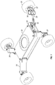
- chassis 10 for supporting an aerial work platform apparatus such as an extendable boom lift for elevating and lowering a work platform.
- An aerial work platform apparatus such as an extendable boom lift for elevating and lowering a work platform.
- chassis support legs 20 are pivotally connected to the chassis.
- Wheel assemblies 30 affixed at the outer ends of the support legs are laterally positioned relative to the chassis 10 as desired by linear actuators such that each of the wheel assemblies can be moved between a position close to the chassis 10 for transporting the apparatus on a trailer and a more stable working position in which the wheel assemblies are spaced further from the chassis.
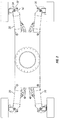
- FIGS 2 and 3 show the angular range of movement of the chassis support legs 20 and of the wheel assemblies 30.
- Support leg deployment actuators 40 preferably comprise hydraulic piston/cylinder units 40 having cylinder ends 44 pivotally connected to the chassis by pins 46 supported in end brackets 47 welded to the body of the chassis. Piston ends 42 of the deployment actuators are pivotally connected to the support legs 20 at 48.
- the chassis support legs 20 pivot relative to the chassis over a range of angles from less than 15° (transport position) to the chassis longitudinal centerline to a working width of about 45 ° to the chassis centerline to attain a transport width across the tires of about 8 1 ⁇ 2 feet and a working width of about 13 feet.
- the chassis support legs 20 are preferably rectangular in cross section comprised of flat upper, lower and side plates of steel to provide interior space adequate for protective containment of the linear actuators 50 which steer the wheels.
- the ends of the steering cylinders 54 are pivotally connected to inner end brackets 60 welded or otherwise rigidly affixed to the body of the chassis 10 and, referring to Figs. 4 and 5 , the ends of the steering pistons 52 are connected to steering pins 36 at the steering yokes 32 for positioning the steering angle of the wheels whereby the steering actuators 50 are protectively positioned in the support legs 20.
- FIG. 1 one chassis support leg 20 is partially broken away, revealing a wheel steering linear actuator 50 positioned in a new and beneficial protected location interiorly of the support leg 20.
- Each steerable wheel assembly 30 includes a wheel and a steering yoke 32.
- an end of the piston 52 of the associated linear wheel steering actuator 50 is pivotally connected to the yoke 32.
- all four wheel assemblies are steerable.
- FIG. 4 and 5 Pivotal connections of the chassis support legs 20 with the wheel assemblies 30 and pivotal connections of the wheel steering linear actuators 50 are shown in Figs. 4 and 5 .
- a parallelogram linkage seen in dashed lines in Fig. 5 is provided by: (a) the fixed length chassis support legs 20 between 22 and 34; (b) the straight ahead steering length between 36 and 58 of the steering linear actuators 50; (c) the fixed length of the steering yokes 32 between the kingpins 34 and the steering pins 36; and (d) the fixed length between the pivotal connections of the support legs 20 to the chassis and the pivotal connections of the steering actuators 50 to the inner end brackets 60.
- the parallelogram linkage remains in a fixed configuration to maintain a straight ahead steering direction of the wheel assemblies 30 during deployment of the chassis support legs 20 from the transport to the working position.
- the steering angle of the wheels 23 may then be selected by varying the length of the linear actuators 50 once the support legs have been deployed to the working position,
- Steering cylinders for aerial work platform apparatus are conventionally located close to the wheels with the hydraulic steer cylinders oriented substantially perpendicular to the maj or axis of the vehicle. This places the steer cylinder units in positions vulnerable to impact damage and sturdy framework must be used to protect the steering cylinder units from damage in the event of an impact.
- the deployment or retraction of the chassis support legs 20 necessitates slow forward or rearward driving while simultaneously operating the leg deployment actuators 40.
- Safe practice and operation requires that the apparatus be driven in a straight direction.
- the parallelogram linkage disclosed herein is employed to prevent the wheels from changing direction as they move between transport and working locations by freezing, i.e., preventing any change in length, of the wheel steering actuator 50 in the four bar linkage.
- the steering actuators 50 located inside the large hollow chassis support legs, they are not only well protected but present a significantly smaller frontal area subject to impacts.
- Use of the steering actuators 50 as one link of the 4-bar parallelogram linkages inherently self-maintains the steering wheels in the same straight ahead wheel direction during chassis support leg deployment and retraction.
- Chassis support leg extension or retraction is initiated as the machine is driven forward or backward in slow speed by simultaneously supplying pressurized hydraulic fluid to each of the four support leg deployment cylinders preferably only when the machine is in motion.
- the support legs sequentially deploy in an order depending on the load in each cylinder such that the lightest loaded will reach full deployment first. During deployment as the vehicle slowly moves, the wheels thereby roll in a diagonal direction leaving insignificant evidence of scrubbing action on the support surface.
Landscapes
- Engineering & Computer Science (AREA)
- Mechanical Engineering (AREA)
- Structural Engineering (AREA)
- Chemical & Material Sciences (AREA)
- Combustion & Propulsion (AREA)
- Transportation (AREA)
- Life Sciences & Earth Sciences (AREA)
- Geology (AREA)
- Steering-Linkage Mechanisms And Four-Wheel Steering (AREA)
- Forklifts And Lifting Vehicles (AREA)
Abstract
Description
- This disclosure pertains to wheel extension and steering apparatus, particularlyuseful for aerial work platform machines such as articulated and telescopic boom lifts which raise a work platform to desired elevation. The apparatus comprises a chassis and chassis support legs pivotally connected to the chassis to position steerable wheels at the ends of the chassis support legs whereby the wheels may be moved between transport positions close to the chassis and working positions at greater distance from the chassis to provide vehicle stability. In apparatus of this type, linear actuators, usually hydraulic, for steering the wheels are aligned generally transverse to the longitudinal axis of the vehicle since they must overcome considerable moment resistance as the extremes of steering angle are approached. Orientation of the linear actuators transversely to the longitudinal axis of the vehicle necessarily exposes the full length of the steering actuators to damage during movement of the vehicle.
- Disclosed herein is a vehicle wheel positioning and steering apparatus comprising a support chassis, chassis support legs pivotally connected to the chassis, steerable wheel assemblies operably connected at outer ends of the support legs, powered actuators operably connected to the chassis and legs for pivotally moving the legs and wheel assemblies relative to the chassis between transport and working positions and powered linear wheel steering actuators, the steering linear actuators comprising first bars of four bar parallelogram steering linkages between the chassis and wheel assemblies and the support legs comprising second bars of the four bar parallelogram steering linkages.
- The vehicle wheel position and steering apparatus of the preceding paragraph is particularly useful in a mobile aerial work platform apparatus which includes a work platform mounted on the chassis and means such as an articulated boom or a telescopic boom for raising and lowering the aerial work platform relative to the chassis.
-
-
Figure 1 is a perspective view of a support chassis for an aerial work platform apparatus. -
Figure 2 is a plan view of the chassis with the wheels in straight ahead steering position and the chassis support legs in a retracted transport position. -
Figure 3 is a plan view of the chassis showing the wheels in a straight ahead steering position and the chassis support legs in an extended working position. -
Figure 4 is a perspective view to an enlarged scale partly broken away to show connections of a chassis support leg and wheel assembly. -
Figure 5 is a partial plan view with dashed lines indicating parallelogram steering linkage. -
Fig. 6 is an enlarged perspective, partly broken away, of the inner end connections of one of the support legs and interiorly positioned linear steering actuators to the chassis. -
Fig. 7 is a cross sectional elevation view taken at lines 7-7 ofFig. 6 . - As seen in
Fig. 1 rigid chassis 10 for supporting an aerial work platform apparatus such as an extendable boom lift for elevating and lowering a work platform. Fourchassis support legs 20 are pivotally connected to the chassis. -
Wheel assemblies 30 affixed at the outer ends of the support legs are laterally positioned relative to thechassis 10 as desired by linear actuators such that each of the wheel assemblies can be moved between a position close to thechassis 10 for transporting the apparatus on a trailer and a more stable working position in which the wheel assemblies are spaced further from the chassis. -
Figures 2 and3 show the angular range of movement of thechassis support legs 20 and of thewheel assemblies 30. Supportleg deployment actuators 40 preferably comprise hydraulic piston/cylinder units 40 havingcylinder ends 44 pivotally connected to the chassis bypins 46 supported inend brackets 47 welded to the body of the chassis. Piston ends 42 of the deployment actuators are pivotally connected to thesupport legs 20 at 48. In the presently preferred design, thechassis support legs 20 pivot relative to the chassis over a range of angles from less than 15° (transport position) to the chassis longitudinal centerline to a working width of about 45 ° to the chassis centerline to attain a transport width across the tires of about 8 ½ feet and a working width of about 13 feet. - The
chassis support legs 20 are preferably rectangular in cross section comprised of flat upper, lower and side plates of steel to provide interior space adequate for protective containment of thelinear actuators 50 which steer the wheels. As seen inFig. 6 , in the presently preferred embodiment, the ends of thesteering cylinders 54 are pivotally connected toinner end brackets 60 welded or otherwise rigidly affixed to the body of thechassis 10 and, referring toFigs. 4 and5 , the ends of thesteering pistons 52 are connected tosteering pins 36 at thesteering yokes 32 for positioning the steering angle of the wheels whereby thesteering actuators 50 are protectively positioned in thesupport legs 20. - In
Fig. 1 , onechassis support leg 20 is partially broken away, revealing a wheel steeringlinear actuator 50 positioned in a new and beneficial protected location interiorly of thesupport leg 20. Eachsteerable wheel assembly 30 includes a wheel and asteering yoke 32. As shown inFig. 4 , an end of thepiston 52 of the associated linearwheel steering actuator 50 is pivotally connected to theyoke 32. Preferably, all four wheel assemblies are steerable. - Pivotal connections of the
chassis support legs 20 with thewheel assemblies 30 and pivotal connections of the wheel steeringlinear actuators 50 are shown inFigs. 4 and5 . A parallelogram linkage seen in dashed lines inFig. 5 , is provided by: (a) the fixed lengthchassis support legs 20 between 22 and 34; (b) the straight ahead steering length between 36 and 58 of the steeringlinear actuators 50; (c) the fixed length of thesteering yokes 32 between thekingpins 34 and thesteering pins 36; and (d) the fixed length between the pivotal connections of thesupport legs 20 to the chassis and the pivotal connections of thesteering actuators 50 to theinner end brackets 60. The parallelogram linkage remains in a fixed configuration to maintain a straight ahead steering direction of the wheel assemblies 30 during deployment of thechassis support legs 20 from the transport to the working position. The steering angle of the wheels 23 may then be selected by varying the length of thelinear actuators 50 once the support legs have been deployed to the working position, - Steering cylinders for aerial work platform apparatus are conventionally located close to the wheels with the hydraulic steer cylinders oriented substantially perpendicular to the maj or axis of the vehicle. This places the steer cylinder units in positions vulnerable to impact damage and sturdy framework must be used to protect the steering cylinder units from damage in the event of an impact.
- The deployment or retraction of the
chassis support legs 20 necessitates slow forward or rearward driving while simultaneously operating theleg deployment actuators 40. Safe practice and operation requires that the apparatus be driven in a straight direction. The parallelogram linkage disclosed herein is employed to prevent the wheels from changing direction as they move between transport and working locations by freezing, i.e., preventing any change in length, of thewheel steering actuator 50 in the four bar linkage. With thesteering actuators 50 located inside the large hollow chassis support legs, they are not only well protected but present a significantly smaller frontal area subject to impacts. Use of thesteering actuators 50 as one link of the 4-bar parallelogram linkages inherently self-maintains the steering wheels in the same straight ahead wheel direction during chassis support leg deployment and retraction. - Neither the vehicle operator nor an intervention from the machine control system is needed to adjust the wheel steering angle since the machine wheels should be in the straight ahead position prior to deployment of the wheels to the working position. The steering function can still be enabled if the operator needs to make a steering correction. Chassis support leg extension or retraction is initiated as the machine is driven forward or backward in slow speed by simultaneously supplying pressurized hydraulic fluid to each of the four support leg deployment cylinders preferably only when the machine is in motion. The support legs sequentially deploy in an order depending on the load in each cylinder such that the lightest loaded will reach full deployment first. During deployment as the vehicle slowly moves, the wheels thereby roll in a diagonal direction leaving insignificant evidence of scrubbing action on the support surface.
- Persons skilled in the art will also appreciate that various additional modifications can be made in the preferred embodiment shown and described above and that the scope of protection is limited only by the wording of the claims which follow.
Claims (15)
- A vehicle wheel positioning and steering apparatus comprising a support chassis, chassis support legs pivotally connected to the chassis, steerable wheel assemblies operably connected at outer ends of said support legs, powered actuators operably connected to said chassis and said legs for pivotally moving said legs and wheel assemblies relative to said chassis between transport and working positions and powered linear wheel steering actuators, said linear actuators comprising first bars of four bar parallelogram steering linkages between said chassis and said wheel assemblies and said support legs comprising second bars of said four bar parallelogram steering linkages.
- The apparatus of claim 1, further comprising inner end brackets pivotally connected to said chassis and a linear actuator, said inner end brackets comprising third bars of said four bar parallelogram steering linkages.
- The apparatus of claim 2, wherein said wheel assemblies each include a yoke having pivotal connections to a support leg and a steering actuator, said yokes comprising fourth bars of said four bar parallelogram steering linkage.
- The apparatus of claim 3, wherein said steering actuators are positioned in protected locations in said support legs.
- The apparatus of claim 4, wherein said steering actuators have piston ends pivotally connected to said yokes and cylinder ends pivotally connected to said chassis.
- The apparatus of claim 5, wherein said steering actuators comprise hydraulic piston/cylinder units.
- The apparatus of claim 6, further including powered actuators for positioning said support legs and wheel assemblies relative to said chassis, said powered actuators comprising linear actuators pivotally connected between said chassis and said support legs.
- The apparatus of claim 7, wherein there are four of said chassis support legs and wheel assemblies.
- A mobile aerial work platform apparatus including a support chassis, a work platform mounted on said chassis, means for raising and lowering the platform relative to said chassis, chassis support legs pivotally connected to the chassis, steerable wheel assemblies operably connected at outer ends of said support legs, powered actuators operably connected to said chassis and said legs for pivotally moving said legs and wheel assemblies relative to said chassis between transport and working positions and powered linear wheel steering actuators, said linear actuators comprising first bars of four bar parallelogram steering linkages between said chassis and said wheel assemblies and said support legs comprising second bars of said four bar parallelogram steering linkages.
- The apparatus of claim 9, further comprising inner end brackets pivotally connected to said chassis and a linear actuator, said inner end brackets comprising third bars of said four bar parallelogram steering linkages.
- The apparatus of claim 10, wherein said wheel assemblies each include a yoke having pivotal connections to a support leg and a steering actuator, said yokes comprising fourth bars of said four bar parallelogram steering linkage.
- The apparatus of claim 11, wherein said steering actuators are positioned in protected locations in said support legs.
- The apparatus of claim 12, wherein said steering actuators have piston ends pivotally connected to said yokes and cylinder ends pivotally connected to said chassis.
- The apparatus of claim 13, wherein said steering actuators comprise hydraulic piston/cylinder units.
- The apparatus of claim 14, further including powered actuators for positioning said support legs and wheel assemblies relative to said chassis, said powered actuators comprising linear actuators pivotally connected between said chassis and said support legs.
Applications Claiming Priority (2)
| Application Number | Priority Date | Filing Date | Title |
|---|---|---|---|
| US201762540373P | 2017-08-02 | 2017-08-02 | |
| US15/849,751 US10562364B2 (en) | 2017-08-02 | 2017-12-21 | Vehicle wheel positioning and steering apparatus |
Publications (2)
| Publication Number | Publication Date |
|---|---|
| EP3437962A1 true EP3437962A1 (en) | 2019-02-06 |
| EP3437962B1 EP3437962B1 (en) | 2021-09-01 |
Family
ID=62947997
Family Applications (1)
| Application Number | Title | Priority Date | Filing Date |
|---|---|---|---|
| EP18183122.3A Active EP3437962B1 (en) | 2017-08-02 | 2018-07-12 | Vehicle wheel positioning and steering apparatus |
Country Status (3)
| Country | Link |
|---|---|
| US (1) | US10562364B2 (en) |
| EP (1) | EP3437962B1 (en) |
| CA (1) | CA3011992C (en) |
Cited By (3)
| Publication number | Priority date | Publication date | Assignee | Title |
|---|---|---|---|---|
| CN110539820A (en) * | 2019-09-16 | 2019-12-06 | 北京理工大学 | vehicle with a steering wheel |
| CN110667702A (en) * | 2019-09-16 | 2020-01-10 | 中联重科股份有限公司 | Swing arm structure and machineshop car of machineshop car |
| DE102020130811A1 (en) | 2020-11-20 | 2022-05-25 | Teupen Maschinenbau Gmbh | chassis and its use |
Families Citing this family (15)
| Publication number | Priority date | Publication date | Assignee | Title |
|---|---|---|---|---|
| BE1022561A9 (en) * | 2014-10-14 | 2016-11-30 | Reybrouck Consulting & Innovation Bvba | Wheel suspension |
| US10197049B2 (en) * | 2016-06-16 | 2019-02-05 | D3 Innovation Inc. | Portable storage device for bicycle tools |
| BR112019014450A2 (en) * | 2017-01-13 | 2020-04-28 | Triggo S A | suspension system for a vehicle |
| GB2560328B (en) * | 2017-03-07 | 2021-12-15 | Niftylift Ltd | Base unit for a vehicle |
| CA3118724C (en) | 2018-11-05 | 2024-06-11 | Oshkosh Corporation | Leveling system for lift device |
| US11730073B2 (en) * | 2018-11-28 | 2023-08-22 | Agco Corporation | Mounting assembly for a steerable wheel with variable track width |
| US11608126B2 (en) | 2020-01-16 | 2023-03-21 | Xtreme Manufacturing, Llc | Expendable wheel base chassis |
| US11679625B2 (en) * | 2020-08-28 | 2023-06-20 | Zoomlion Heavy Industry N.A, Inc. | Offset extendable axle with wheels on common centerline |
| US11785886B1 (en) * | 2020-09-01 | 2023-10-17 | Bad Boy Mowers, Llc | Zero-turn-radius riding mower front wheel positioning system |
| AT17140U3 (en) * | 2021-02-23 | 2021-11-15 | Kaiser Ag | Walking excavator |
| CN113152549B (en) * | 2021-03-04 | 2022-05-17 | 中国人民解放军63983部队 | Control method of wheel-leg combined type excavator autonomous displacement control system |
| CN113022220B (en) * | 2021-03-24 | 2022-04-15 | 燕山大学 | A high-passage multi-mode walking chassis |
| US20240342895A1 (en) * | 2023-04-06 | 2024-10-17 | Verifi Technologies, Llc | Deployable robotic arm mount |
| CN116674649A (en) * | 2023-06-05 | 2023-09-01 | 三峡大学 | An articulated chassis with variable wheelbase for parallel moving wheels |
| US20250136423A1 (en) * | 2023-10-26 | 2025-05-01 | Oshkosh Corporation | Vehicle with pendulum axles |
Citations (5)
| Publication number | Priority date | Publication date | Assignee | Title |
|---|---|---|---|---|
| US5137101A (en) * | 1989-09-28 | 1992-08-11 | Hans Schaeff | Cross-country vehicle with stepwise locomotion |
| US6443687B1 (en) * | 1997-05-23 | 2002-09-03 | Kaiser Aktiengesellschaft | Excavator-hoist |
| US20040129491A1 (en) * | 2003-01-07 | 2004-07-08 | Bean Andrew J. | Vehicle with offset extendible axles and independent four-wheel steering control |
| EP2641860A1 (en) * | 2012-03-19 | 2013-09-25 | JLG Industries Inc. | Pivoting axle system |
| EP3023544A1 (en) * | 2014-11-13 | 2016-05-25 | Wirtgen GmbH | Transport mode conversion |
Family Cites Families (13)
| Publication number | Priority date | Publication date | Assignee | Title |
|---|---|---|---|---|
| US3899037A (en) * | 1973-07-16 | 1975-08-12 | Paul A Yuker | Chassis apparatus for all terrain vehicles |
| AT375703B (en) * | 1979-12-24 | 1984-09-10 | Kaiser Josef | EXCAVATOR |
| PT74697B (en) * | 1981-05-15 | 1983-10-25 | Menzi Ag Ernst | DREDGING |
| US4558758A (en) * | 1983-12-02 | 1985-12-17 | Erwin Littman | Prime mover |
| JPH0784186B2 (en) * | 1985-08-13 | 1995-09-13 | ウェルダ−,マルティン | Slope running vehicle |
| US6119882A (en) | 1998-12-04 | 2000-09-19 | Upright, Inc. | Self-propelled boom with extendible axles |
| US6293579B1 (en) * | 1999-03-08 | 2001-09-25 | Karl Schaeff Gmbh & Co Maschinenfabrik | Mobile rig on wheels with transverse motion |
| DE10009736B4 (en) * | 2000-02-23 | 2004-04-15 | Atecs Mannesmann Ag | Mobile harbor crane for combined container and bulk handling |
| US7198278B2 (en) | 2004-03-24 | 2007-04-03 | Genie Industries, Inc. | Vehicle support system |
| US9434412B2 (en) * | 2010-08-23 | 2016-09-06 | Terex South Dakota, Inc. | Apparatuses and methods for steering a vehicle |
| US9174488B2 (en) | 2012-03-19 | 2015-11-03 | Jlg Industries, Inc. | Pivoting axle system |
| US9387881B2 (en) * | 2013-11-18 | 2016-07-12 | Terra Drive Systems, Inc. | Land vehicle steering system including selective inboard and outboard wheels adjustment |
| US9499348B2 (en) * | 2014-05-23 | 2016-11-22 | Ty-Crop Manufacturing Ltd. | Material handling conveyor vehicle |
-
2017
- 2017-12-21 US US15/849,751 patent/US10562364B2/en active Active
-
2018
- 2018-07-12 EP EP18183122.3A patent/EP3437962B1/en active Active
- 2018-07-20 CA CA3011992A patent/CA3011992C/en active Active
Patent Citations (5)
| Publication number | Priority date | Publication date | Assignee | Title |
|---|---|---|---|---|
| US5137101A (en) * | 1989-09-28 | 1992-08-11 | Hans Schaeff | Cross-country vehicle with stepwise locomotion |
| US6443687B1 (en) * | 1997-05-23 | 2002-09-03 | Kaiser Aktiengesellschaft | Excavator-hoist |
| US20040129491A1 (en) * | 2003-01-07 | 2004-07-08 | Bean Andrew J. | Vehicle with offset extendible axles and independent four-wheel steering control |
| EP2641860A1 (en) * | 2012-03-19 | 2013-09-25 | JLG Industries Inc. | Pivoting axle system |
| EP3023544A1 (en) * | 2014-11-13 | 2016-05-25 | Wirtgen GmbH | Transport mode conversion |
Cited By (8)
| Publication number | Priority date | Publication date | Assignee | Title |
|---|---|---|---|---|
| CN110539820A (en) * | 2019-09-16 | 2019-12-06 | 北京理工大学 | vehicle with a steering wheel |
| CN110667702A (en) * | 2019-09-16 | 2020-01-10 | 中联重科股份有限公司 | Swing arm structure and machineshop car of machineshop car |
| DE102020130811A1 (en) | 2020-11-20 | 2022-05-25 | Teupen Maschinenbau Gmbh | chassis and its use |
| WO2022106280A1 (en) * | 2020-11-20 | 2022-05-27 | Teupen Maschinenbau Gmbh | Chassis and use thereof |
| CN116457222A (en) * | 2020-11-20 | 2023-07-18 | 德国拓鹏机械有限公司 | Chassis and application thereof |
| AU2021381549B2 (en) * | 2020-11-20 | 2024-03-28 | Zhejiang Dingli Machinery Co., Ltd | Chassis and use thereof |
| AU2021381549A9 (en) * | 2020-11-20 | 2024-10-24 | Zhejiang Dingli Machinery Co., Ltd | Chassis and use thereof |
| CN116457222B (en) * | 2020-11-20 | 2025-10-28 | 浙江鼎力机械股份有限公司 | Chassis and its applications |
Also Published As
| Publication number | Publication date |
|---|---|
| CA3011992A1 (en) | 2019-02-02 |
| US20190039430A1 (en) | 2019-02-07 |
| US10562364B2 (en) | 2020-02-18 |
| EP3437962B1 (en) | 2021-09-01 |
| CA3011992C (en) | 2023-10-03 |
Similar Documents
| Publication | Publication Date | Title |
|---|---|---|
| CA3011992C (en) | Vehicle wheel positioning and steering apparatus | |
| US5489114A (en) | Tie rod extendable and retractable telescopic axle assembly | |
| US8944466B2 (en) | Vehicle outrigger and stabilized vehicle using same | |
| US6616398B2 (en) | Lift boom assembly | |
| US9340956B2 (en) | Boom lock system for work machine | |
| EP3538475B1 (en) | Base unit for a lifting vehicle | |
| US12084120B2 (en) | Extendable wheel base chassis and methods of operating same | |
| US9834423B2 (en) | Lift truck equipped with stabilizer means | |
| US20180170322A1 (en) | Powered rear outrigger systems | |
| EP1531141B1 (en) | Piggyback forklift truck | |
| ES2710208T3 (en) | Low frame semi-trailer | |
| US7721831B2 (en) | Construction machinery and pivoting device | |
| GB2082986A (en) | Variable Track Width Steering Systems | |
| KR20090061601A (en) | Elevated Aerial Devices and Vehicles Where They Are Installed | |
| US11597435B2 (en) | Drilling rig | |
| CA3102301C (en) | Operating machine with improved stabilisers | |
| US3338442A (en) | Loading apparatus | |
| JP2023150116A (en) | boom sprayer | |
| JP3958607B2 (en) | Work equipment | |
| JPS60213699A (en) | Height service car |
Legal Events
| Date | Code | Title | Description |
|---|---|---|---|
| PUAI | Public reference made under article 153(3) epc to a published international application that has entered the european phase |
Free format text: ORIGINAL CODE: 0009012 |
|
| STAA | Information on the status of an ep patent application or granted ep patent |
Free format text: STATUS: THE APPLICATION HAS BEEN PUBLISHED |
|
| AK | Designated contracting states |
Kind code of ref document: A1 Designated state(s): AL AT BE BG CH CY CZ DE DK EE ES FI FR GB GR HR HU IE IS IT LI LT LU LV MC MK MT NL NO PL PT RO RS SE SI SK SM TR |
|
| AX | Request for extension of the european patent |
Extension state: BA ME |
|
| STAA | Information on the status of an ep patent application or granted ep patent |
Free format text: STATUS: REQUEST FOR EXAMINATION WAS MADE |
|
| 17P | Request for examination filed |
Effective date: 20190308 |
|
| RBV | Designated contracting states (corrected) |
Designated state(s): AL AT BE BG CH CY CZ DE DK EE ES FI FR GB GR HR HU IE IS IT LI LT LU LV MC MK MT NL NO PL PT RO RS SE SI SK SM TR |
|
| STAA | Information on the status of an ep patent application or granted ep patent |
Free format text: STATUS: EXAMINATION IS IN PROGRESS |
|
| 17Q | First examination report despatched |
Effective date: 20200331 |
|
| GRAP | Despatch of communication of intention to grant a patent |
Free format text: ORIGINAL CODE: EPIDOSNIGR1 |
|
| STAA | Information on the status of an ep patent application or granted ep patent |
Free format text: STATUS: GRANT OF PATENT IS INTENDED |
|
| INTG | Intention to grant announced |
Effective date: 20210319 |
|
| GRAS | Grant fee paid |
Free format text: ORIGINAL CODE: EPIDOSNIGR3 |
|
| GRAA | (expected) grant |
Free format text: ORIGINAL CODE: 0009210 |
|
| STAA | Information on the status of an ep patent application or granted ep patent |
Free format text: STATUS: THE PATENT HAS BEEN GRANTED |
|
| AK | Designated contracting states |
Kind code of ref document: B1 Designated state(s): AL AT BE BG CH CY CZ DE DK EE ES FI FR GB GR HR HU IE IS IT LI LT LU LV MC MK MT NL NO PL PT RO RS SE SI SK SM TR |
|
| REG | Reference to a national code |
Ref country code: GB Ref legal event code: FG4D |
|
| REG | Reference to a national code |
Ref country code: CH Ref legal event code: EP Ref country code: AT Ref legal event code: REF Ref document number: 1425957 Country of ref document: AT Kind code of ref document: T Effective date: 20210915 |
|
| REG | Reference to a national code |
Ref country code: DE Ref legal event code: R096 Ref document number: 602018022695 Country of ref document: DE |
|
| REG | Reference to a national code |
Ref country code: IE Ref legal event code: FG4D |
|
| REG | Reference to a national code |
Ref country code: NL Ref legal event code: FP |
|
| REG | Reference to a national code |
Ref country code: SE Ref legal event code: TRGR |
|
| REG | Reference to a national code |
Ref country code: LT Ref legal event code: MG9D |
|
| PG25 | Lapsed in a contracting state [announced via postgrant information from national office to epo] |
Ref country code: RS Free format text: LAPSE BECAUSE OF FAILURE TO SUBMIT A TRANSLATION OF THE DESCRIPTION OR TO PAY THE FEE WITHIN THE PRESCRIBED TIME-LIMIT Effective date: 20210901 Ref country code: HR Free format text: LAPSE BECAUSE OF FAILURE TO SUBMIT A TRANSLATION OF THE DESCRIPTION OR TO PAY THE FEE WITHIN THE PRESCRIBED TIME-LIMIT Effective date: 20210901 Ref country code: ES Free format text: LAPSE BECAUSE OF FAILURE TO SUBMIT A TRANSLATION OF THE DESCRIPTION OR TO PAY THE FEE WITHIN THE PRESCRIBED TIME-LIMIT Effective date: 20210901 Ref country code: FI Free format text: LAPSE BECAUSE OF FAILURE TO SUBMIT A TRANSLATION OF THE DESCRIPTION OR TO PAY THE FEE WITHIN THE PRESCRIBED TIME-LIMIT Effective date: 20210901 Ref country code: LT Free format text: LAPSE BECAUSE OF FAILURE TO SUBMIT A TRANSLATION OF THE DESCRIPTION OR TO PAY THE FEE WITHIN THE PRESCRIBED TIME-LIMIT Effective date: 20210901 Ref country code: BG Free format text: LAPSE BECAUSE OF FAILURE TO SUBMIT A TRANSLATION OF THE DESCRIPTION OR TO PAY THE FEE WITHIN THE PRESCRIBED TIME-LIMIT Effective date: 20211201 Ref country code: NO Free format text: LAPSE BECAUSE OF FAILURE TO SUBMIT A TRANSLATION OF THE DESCRIPTION OR TO PAY THE FEE WITHIN THE PRESCRIBED TIME-LIMIT Effective date: 20211201 |
|
| REG | Reference to a national code |
Ref country code: AT Ref legal event code: MK05 Ref document number: 1425957 Country of ref document: AT Kind code of ref document: T Effective date: 20210901 |
|
| PG25 | Lapsed in a contracting state [announced via postgrant information from national office to epo] |
Ref country code: PL Free format text: LAPSE BECAUSE OF FAILURE TO SUBMIT A TRANSLATION OF THE DESCRIPTION OR TO PAY THE FEE WITHIN THE PRESCRIBED TIME-LIMIT Effective date: 20210901 Ref country code: LV Free format text: LAPSE BECAUSE OF FAILURE TO SUBMIT A TRANSLATION OF THE DESCRIPTION OR TO PAY THE FEE WITHIN THE PRESCRIBED TIME-LIMIT Effective date: 20210901 Ref country code: GR Free format text: LAPSE BECAUSE OF FAILURE TO SUBMIT A TRANSLATION OF THE DESCRIPTION OR TO PAY THE FEE WITHIN THE PRESCRIBED TIME-LIMIT Effective date: 20211202 |
|
| PG25 | Lapsed in a contracting state [announced via postgrant information from national office to epo] |
Ref country code: AT Free format text: LAPSE BECAUSE OF FAILURE TO SUBMIT A TRANSLATION OF THE DESCRIPTION OR TO PAY THE FEE WITHIN THE PRESCRIBED TIME-LIMIT Effective date: 20210901 |
|
| PG25 | Lapsed in a contracting state [announced via postgrant information from national office to epo] |
Ref country code: IS Free format text: LAPSE BECAUSE OF FAILURE TO SUBMIT A TRANSLATION OF THE DESCRIPTION OR TO PAY THE FEE WITHIN THE PRESCRIBED TIME-LIMIT Effective date: 20220101 Ref country code: SM Free format text: LAPSE BECAUSE OF FAILURE TO SUBMIT A TRANSLATION OF THE DESCRIPTION OR TO PAY THE FEE WITHIN THE PRESCRIBED TIME-LIMIT Effective date: 20210901 Ref country code: SK Free format text: LAPSE BECAUSE OF FAILURE TO SUBMIT A TRANSLATION OF THE DESCRIPTION OR TO PAY THE FEE WITHIN THE PRESCRIBED TIME-LIMIT Effective date: 20210901 Ref country code: RO Free format text: LAPSE BECAUSE OF FAILURE TO SUBMIT A TRANSLATION OF THE DESCRIPTION OR TO PAY THE FEE WITHIN THE PRESCRIBED TIME-LIMIT Effective date: 20210901 Ref country code: PT Free format text: LAPSE BECAUSE OF FAILURE TO SUBMIT A TRANSLATION OF THE DESCRIPTION OR TO PAY THE FEE WITHIN THE PRESCRIBED TIME-LIMIT Effective date: 20220103 Ref country code: EE Free format text: LAPSE BECAUSE OF FAILURE TO SUBMIT A TRANSLATION OF THE DESCRIPTION OR TO PAY THE FEE WITHIN THE PRESCRIBED TIME-LIMIT Effective date: 20210901 Ref country code: CZ Free format text: LAPSE BECAUSE OF FAILURE TO SUBMIT A TRANSLATION OF THE DESCRIPTION OR TO PAY THE FEE WITHIN THE PRESCRIBED TIME-LIMIT Effective date: 20210901 Ref country code: AL Free format text: LAPSE BECAUSE OF FAILURE TO SUBMIT A TRANSLATION OF THE DESCRIPTION OR TO PAY THE FEE WITHIN THE PRESCRIBED TIME-LIMIT Effective date: 20210901 |
|
| REG | Reference to a national code |
Ref country code: DE Ref legal event code: R097 Ref document number: 602018022695 Country of ref document: DE |
|
| PLBE | No opposition filed within time limit |
Free format text: ORIGINAL CODE: 0009261 |
|
| STAA | Information on the status of an ep patent application or granted ep patent |
Free format text: STATUS: NO OPPOSITION FILED WITHIN TIME LIMIT |
|
| PG25 | Lapsed in a contracting state [announced via postgrant information from national office to epo] |
Ref country code: IT Free format text: LAPSE BECAUSE OF FAILURE TO SUBMIT A TRANSLATION OF THE DESCRIPTION OR TO PAY THE FEE WITHIN THE PRESCRIBED TIME-LIMIT Effective date: 20210901 Ref country code: DK Free format text: LAPSE BECAUSE OF FAILURE TO SUBMIT A TRANSLATION OF THE DESCRIPTION OR TO PAY THE FEE WITHIN THE PRESCRIBED TIME-LIMIT Effective date: 20210901 |
|
| 26N | No opposition filed |
Effective date: 20220602 |
|
| PG25 | Lapsed in a contracting state [announced via postgrant information from national office to epo] |
Ref country code: SI Free format text: LAPSE BECAUSE OF FAILURE TO SUBMIT A TRANSLATION OF THE DESCRIPTION OR TO PAY THE FEE WITHIN THE PRESCRIBED TIME-LIMIT Effective date: 20210901 |
|
| PG25 | Lapsed in a contracting state [announced via postgrant information from national office to epo] |
Ref country code: MC Free format text: LAPSE BECAUSE OF FAILURE TO SUBMIT A TRANSLATION OF THE DESCRIPTION OR TO PAY THE FEE WITHIN THE PRESCRIBED TIME-LIMIT Effective date: 20210901 |
|
| REG | Reference to a national code |
Ref country code: CH Ref legal event code: PL |
|
| REG | Reference to a national code |
Ref country code: BE Ref legal event code: MM Effective date: 20220731 |
|
| PG25 | Lapsed in a contracting state [announced via postgrant information from national office to epo] |
Ref country code: LU Free format text: LAPSE BECAUSE OF NON-PAYMENT OF DUE FEES Effective date: 20220712 Ref country code: LI Free format text: LAPSE BECAUSE OF NON-PAYMENT OF DUE FEES Effective date: 20220731 Ref country code: CH Free format text: LAPSE BECAUSE OF NON-PAYMENT OF DUE FEES Effective date: 20220731 |
|
| PG25 | Lapsed in a contracting state [announced via postgrant information from national office to epo] |
Ref country code: BE Free format text: LAPSE BECAUSE OF NON-PAYMENT OF DUE FEES Effective date: 20220731 |
|
| REG | Reference to a national code |
Ref country code: DE Ref legal event code: R082 Ref document number: 602018022695 Country of ref document: DE Representative=s name: MEISSNER BOLTE PATENTANWAELTE RECHTSANWAELTE P, DE |
|
| PG25 | Lapsed in a contracting state [announced via postgrant information from national office to epo] |
Ref country code: IE Free format text: LAPSE BECAUSE OF NON-PAYMENT OF DUE FEES Effective date: 20220712 |
|
| PG25 | Lapsed in a contracting state [announced via postgrant information from national office to epo] |
Ref country code: HU Free format text: LAPSE BECAUSE OF FAILURE TO SUBMIT A TRANSLATION OF THE DESCRIPTION OR TO PAY THE FEE WITHIN THE PRESCRIBED TIME-LIMIT; INVALID AB INITIO Effective date: 20180712 |
|
| PG25 | Lapsed in a contracting state [announced via postgrant information from national office to epo] |
Ref country code: MK Free format text: LAPSE BECAUSE OF FAILURE TO SUBMIT A TRANSLATION OF THE DESCRIPTION OR TO PAY THE FEE WITHIN THE PRESCRIBED TIME-LIMIT Effective date: 20210901 Ref country code: CY Free format text: LAPSE BECAUSE OF FAILURE TO SUBMIT A TRANSLATION OF THE DESCRIPTION OR TO PAY THE FEE WITHIN THE PRESCRIBED TIME-LIMIT Effective date: 20210901 |
|
| PG25 | Lapsed in a contracting state [announced via postgrant information from national office to epo] |
Ref country code: TR Free format text: LAPSE BECAUSE OF FAILURE TO SUBMIT A TRANSLATION OF THE DESCRIPTION OR TO PAY THE FEE WITHIN THE PRESCRIBED TIME-LIMIT Effective date: 20210901 |
|
| PG25 | Lapsed in a contracting state [announced via postgrant information from national office to epo] |
Ref country code: MT Free format text: LAPSE BECAUSE OF FAILURE TO SUBMIT A TRANSLATION OF THE DESCRIPTION OR TO PAY THE FEE WITHIN THE PRESCRIBED TIME-LIMIT Effective date: 20210901 |
|
| PGFP | Annual fee paid to national office [announced via postgrant information from national office to epo] |
Ref country code: FR Payment date: 20250616 Year of fee payment: 8 |
|
| PGFP | Annual fee paid to national office [announced via postgrant information from national office to epo] |
Ref country code: NL Payment date: 20250724 Year of fee payment: 8 |
|
| PGFP | Annual fee paid to national office [announced via postgrant information from national office to epo] |
Ref country code: DE Payment date: 20250716 Year of fee payment: 8 |
|
| PGFP | Annual fee paid to national office [announced via postgrant information from national office to epo] |
Ref country code: GB Payment date: 20250818 Year of fee payment: 8 |
|
| PGFP | Annual fee paid to national office [announced via postgrant information from national office to epo] |
Ref country code: SE Payment date: 20251022 Year of fee payment: 8 |