EP3444146A1 - Energieabsorptionsstruktur - Google Patents
Energieabsorptionsstruktur Download PDFInfo
- Publication number
- EP3444146A1 EP3444146A1 EP16898647.9A EP16898647A EP3444146A1 EP 3444146 A1 EP3444146 A1 EP 3444146A1 EP 16898647 A EP16898647 A EP 16898647A EP 3444146 A1 EP3444146 A1 EP 3444146A1
- Authority
- EP
- European Patent Office
- Prior art keywords
- energy
- absorbing
- absorbing member
- load
- members
- Prior art date
- Legal status (The legal status is an assumption and is not a legal conclusion. Google has not performed a legal analysis and makes no representation as to the accuracy of the status listed.)
- Granted
Links
Images


Classifications
-
- B—PERFORMING OPERATIONS; TRANSPORTING
- B60—VEHICLES IN GENERAL
- B60R—VEHICLES, VEHICLE FITTINGS, OR VEHICLE PARTS, NOT OTHERWISE PROVIDED FOR
- B60R19/00—Wheel guards; Radiator guards, e.g. grilles; Obstruction removers; Fittings damping bouncing force in collisions
- B60R19/02—Bumpers, i.e. impact receiving or absorbing members for protecting vehicles or fending off blows from other vehicles or objects
- B60R19/24—Arrangements for mounting bumpers on vehicles
- B60R19/26—Arrangements for mounting bumpers on vehicles comprising yieldable mounting means
- B60R19/34—Arrangements for mounting bumpers on vehicles comprising yieldable mounting means destroyed upon impact, e.g. one-shot type
-
- B—PERFORMING OPERATIONS; TRANSPORTING
- B60—VEHICLES IN GENERAL
- B60R—VEHICLES, VEHICLE FITTINGS, OR VEHICLE PARTS, NOT OTHERWISE PROVIDED FOR
- B60R19/00—Wheel guards; Radiator guards, e.g. grilles; Obstruction removers; Fittings damping bouncing force in collisions
- B60R19/02—Bumpers, i.e. impact receiving or absorbing members for protecting vehicles or fending off blows from other vehicles or objects
- B60R19/18—Bumpers, i.e. impact receiving or absorbing members for protecting vehicles or fending off blows from other vehicles or objects characterised by the cross-section; Means within the bumper to absorb impact
Definitions
- the present invention relates to an energy-absorbing structure that uses an energy-absorbing member made of fiber-reinforced resin.
- Patent Document 1 discloses an energy-absorbing member made of fiber-reinforced resin that is used in a front side member of the front frame structure of a vehicle body. At the time of a front-end collision of a vehicle the collision load acts on the energy-absorbing member, and the collision energy is absorbed by the crushing of the energy-absorbing member.
- Patent Document 1 Japanese Patent No. 4440683
- An energy-absorbing member made of fiber-reinforced resin absorbs collision energy by means of the deformation of a matrix resin with impregnated reinforcing fibers at the time that the energy-absorbing member is crushed.
- the reinforcing fibers themselves do not readily rupture, the energy absorption efficiency can be further enhanced by causing the reinforcing fibers to rupture.
- an object of the present invention is to further increase the energy absorption efficiency of an energy-absorbing member made of a fiber-reinforced resin.
- a tearing element which tears the energy-absorbing member when a collision load is input from a load-receiving member onto the energy-absorbing member, is provided adjacent the end portion of the energy-absorbing member that corresponds to at least one of the load-receiving member and a frame member.
- the tearing element tears the energy-absorbing member.
- the reinforcing fibers that extend in a direction that intersects the input direction of the impact load are severed, the energy absorption efficiency is further enhanced.
- FIG. 1 illustrates the lower portion of a vehicle body equipped with energy-absorbing members 1 according to a first embodiment of the present invention.
- the energy-absorbing members 1 are a fiber-reinforced resin material formed by impregnating reinforcing fibers, for example carbon fibers, in a matrix resin that is a resin for impregnation.
- the direction indicated by the arrow FR is the front of the vehicle body
- the direction indicated by the arrow LH is the left side of the vehicle body
- the direction indicated by the arrow UP is the up direction of the vehicle body.
- a pair of left and right front side members 3 are disposed on both sides of the front of the vehicle body in the vehicle width direction, along the longitudinal direction of the vehicle body.
- the front side members 3 each constitutes a frame member that forms the frame of the vehicle body and bends downward adjacent the location corresponding to the dash panel 5 and is joined to the lower surface of the floor panel 7.
- the dash panel 5 separates the vehicle cabin 9 and the engine compartment 11.
- Side sills 13 are disposed on both sides of the floor panel 7 in the vehicle width direction along the longitudinal direction of the vehicle body, and a hood ledge panels 15 are disposed on the upper portion of the front side members 3 on the engine compartment side.
- the energy-absorbing members 1 are attached to the front-end portion of the front side members 3.
- a bumper reinforcement 17 is attached to the front-end portion of the energy-absorbing member 1 on the opposite side of the front side members 3.
- the bumper reinforcement 17 is disposed along the vehicle width direction, and both ends thereof project farther outwardly in the vehicle width direction than the energy-absorbing member 1.
- a bumper fascia is attached to the bumper reinforcement 17.
- the front side members 3 are formed in the shape of a quadrangular prism, and includes a front-end flange 3f at the front-end portion on the energy-absorbing member 1 side, as illustrated in Figure 2 .
- a rear-end flange 1f is provided on the rear-end portion of the energy-absorbing member 1 on the side with the front side members 3.
- the front side members 3 and the energy-absorbing members 1 are fixed by causing the front-end flange 3f and the rear-end flange 1f to abut against each other and fastening them with a plurality of nuts 21 and a plurality of bolts 19.
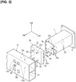
- the energy-absorbing members 1 and the bumper reinforcement 17 are fixed via connecting members 23, as illustrated in Figures 2 and 3 .
- the bumper reinforcement 17 and the connecting members 23 constitute a load-receiving member.
- the energy-absorbing members 1 each have the shape of a quadrangular prism tube, in the same manner as the front side members 3, as illustrated in Figure 3 .
- the connecting members 23 have a quadrangular shape that is larger than the energy-absorbing members 1 in a front view as seen from the front of the vehicle body.
- the connecting members 23 include an end surface portion 25 that abuts the rear surface of the bumper reinforcement 17, and side wall portions 27 that are bent from the four peripheral edges of the end surface portion 25 and that project toward the energy-absorbing member 1.
- the inner side of the bent portion between the end surface portion 25 and the side wall portions 27 forms a concave curved surface portion 29 over the entire perimeter, as illustrated in Figure 2 .
- the bumper reinforcement 17 is a hollow member whose cross-sectional shape is long vertically and has a partition wall 31 in the center in the vertical direction, and spaces having a cross section that is essentially square are formed above and below the partition wall 31.
- Four through-holes 17a are provided on the rear surface of the bumper reinforcement 17, and stud bolts 33 are provided on the end surface portion 25 of the connecting members 23 corresponding to the through-holes 17a.
- the bumper reinforcement 17 and the connecting members 23 are fixed and integrated by inserting the stud bolts 33 into the through-holes 17a, and fastening nuts 35 to the stud bolts 33 by utilizing working holes 17b on the front surface.
- the connecting members 23 When the connecting members 23 are fastened to the energy-absorbing members 1, the four side wall portions 27 in the periphery of the connecting members 23 are attached, so as to cover the peripheral edges of the front-end portion of the energy-absorbing members 1 from the outside. At that time, the side-wall portions 27 of the connecting members 23 overlap the side surfaces 37 as the surface portions of the energy-absorbing members 1 from the outer side adjacent the front-end portion to form overlapping portions 39, as illustrated in Figure 2 . In the overlapping portions 39, the side-wall portions 27 of the connecting members 23 and the side surfaces 37 of the energy-absorbing members 1 overlap in an orthogonal direction that intersects the input direction of the impact load, which is described below.
- a plurality of bolt insertion holes 37a are formed that extend through the side surfaces 37 of the energy-absorbing members 1 in the overlapping portions 39, and nuts 41 are attached on the inner sides of the side surfaces 37 in the periphery of the bolt insertion holes 37a.
- Bolt insertion holes 27a are formed that pass through the side wall portions 27 of the connecting members 23 corresponding to the bolt insertion holes 37a.
- the connecting members 23 and the energy-absorbing members 1 are fixed by inserting bolts 43 as fasteners into the bolt insertion holes 27a, 37a and fastening the bolts to the nuts 41, as illustrated in Figure 2 .
- the bolt insertion holes 27a, 37a constitute mounting holes, which extend through in the overlapping direction of the overlapping portions 39.
- a gap is formed between peripheral front ends 1a of the energy-absorbing members 1 and the end surface portions 25 of the connecting members 23, as illustrated in Figure 2 .
- the curved surface portions 29 of the connecting members 23 are positioned in front of the peripheral front ends 1a of the energy-absorbing members 1, and the peripheral front ends 1a and the curved surface portions 29 face each other.
- the curved surface portions 29 each have a cross section in the form of a quarter arc of a circle.
- the outer surfaces of the side surfaces 37 of the energy-absorbing members 1 are essentially positioned on a line tangent to the end portion of the arc.
- the impact load that is received by the bumper reinforcement 17 when the automobile undergoes a front-end collision is transmitted to the energy-absorbing members 1 via the connecting members 23.
- the energy-absorbing members 1 are crushed and deformed between the bumper reinforcement 17 and the front side members 3, thereby absorbing the impact.
- the impact load is applied to the energy-absorbing members 1 via the fastening portion configured by the bolts 43 of the overlapping portions 39.
- the shaft portions 43a of the bolts 43 are inserted into the bolt insertion holes 27a, 37a.
- the shaft portions 43a of the bolts 43 concentrate the stress in the bolt insertion holes 37a with respect to the energy-absorbing members 1 and becomes the point of origin when the energy-absorbing members 1 is crushed.
- the bolts 43 are provided in two or three locations on one side surface 37 of the energy-absorbing members 1.
- the impact load that is concentrated at and imparted to the bolt insertion holes 37a reaches the side surfaces 37 of the energy-absorbing members 1 for each of the plurality of the bolt insertion holes 37a, as indicated by the arrows P.
- the energy-absorbing members 1 are crushed and torn into multiple pieces along the load input direction with the bolt insertion holes 37a as the points of origin, due to the impact load that is imparted to each of the plurality of the bolt insertion holes 37a. That is, the bolts 43 are provided adjacent the end portion of the energy-absorbing members 1 and function as a tearing element that tears the energy-absorbing members 1 along the load input direction.
- the connecting members 23 moves in the direction toward the front side members 3 and transitions from the state before the impact load is received shown in Figure 5 to the state shown in Figure 6 , so as to crush the energy-absorbing members 1.
- the energy-absorbing members 1 absorb the impact by the inward displacement of the peripheral front ends 1a while being guided by the curved surface portions 29 of the connecting members 23 over the entire perimeter.
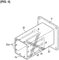
- stud bolts 33 that are similar to those of the connecting members 23 in Figure 3 are omitted.
- reinforcing fibers 47 indicated by the chain double-dashed lines are arranged so as to extend in a direction that intersects the load input direction, which is essentially the same direction as that indicated by the arrows P, at, for example, an approximately 45° angle, as illustrated in Figure 4 .
- the reinforcing fibers 47 are also severed, thereby absorbing the impact load.
- the energy absorption efficiency of the energy-absorbing members 1 is increased.
- Figure 4 and Figure 11 which is described below, only a portion of the reinforcing fibers 47 is shown, but in fact, the reinforcing fibers 47 are provided over the entirety of the energy-absorbing members 1.
- a tearing element that tears the energy-absorbing member 1 is composed of the bolts 43 that fasten and fix the energy-absorbing member 1 and the connecting member 23 on the side of the bumper reinforcement 17.
- the energy-absorbing members 1 have a tubular form, and the side wall portions 27 of the connecting members 23 are attached so as to cover the outer perimeter sides of the tubular energy-absorbing members 1 to form the overlapping portion 39.
- the energy-absorbing members 1 are crushed essentially uniformly over the entire perimeter between the connecting members 23 and the energy-absorbing members, by being displaced inwardly so as to be enveloped by the side wall portions 27 from the outside at the time of collapse, further enhancing the energy absorption efficiency.
- the inner side of the bent portion between the end surface portions 25 and the side wall portions 27 of the connecting members 23 forms a concave curved surface portions 29.
- the energy-absorbing members 1 absorb the impact load more efficiently by the peripheral front ends 1a being smoothly displaced inwardly while being guided by the curved surface portions 29 of the connecting members 23.
- the energy-absorbing members 1 have a prismatic tubular shape, and the bolts 43 that constitute the tearing element are provided at corresponding positions on the side surfaces 37 of the energy-absorbing members 1 formed in a prismatic tubular shape.
- stress can be concentrated not only at the corners of the prismatic tube where stress tends to concentrate but also on the side surfaces 37, which are surface portions, thereby tearing and crushing not only the corners but also the side surfaces 37.
- the tubular energy-absorbing members 1 are crushed essentially uniformly over the entire perimeter, and the energy absorption efficiency becomes extremely high.
- Figures 7 and 8 illustrate a second embodiment of the present invention.
- the shape of the connecting member 23A is different from the connecting members 23 of the first embodiment, as illustrated in Figure 7 .
- the other configurations such as the energy-absorbing members 1 are the same as those of the first embodiment, and the same components have been assigned the same reference symbols, and detailed descriptions thereof have been omitted.
- the side wall portions 27A are positioned farther inward than the outer peripheral edge of the end surface portion 25A.
- the end surface portion 25A has a projecting portion 23Aa whose outer peripheral edge projects outwardly with respect to the side wall portions 27A over the entire perimeter.
- the outer side of the bent portion between the side wall portions 27A and the projecting portion 23Aa forms a concave curved surface portion 29A over the entire perimeter.
- stud bolts 33 that are similar to those of the connecting member 23 in Figure 3 are omitted.
- the quadrangular side wall portions 27A will be inserted inside the energy-absorbing member 1. That is, unlike the first embodiment, in the present embodiment, the side wall portions 27A of the connecting member 23A are overlapped by the side surfaces 37 of the energy-absorbing member 1 from the outside adjacent the front-end portion to form an overlapping portion 39A.
- the curved surface portion 29A of the connecting member 23A is positioned in front of the peripheral front end 1a of the energy-absorbing member 1, and the peripheral front end 1a and the curved surface portion 29A face each other.
- the curved surface portion 29A has a cross section in the form of a quarter arc of a circle.
- the outer surface of the side surfaces 37 of the energy-absorbing member 1 is essentially positioned on a line tangent to the end portion of the arc.
- Bolt insertion holes 27Aa are formed to pass through the side wall portions 27A of the connecting member 23A, corresponding to the bolt insertion holes 37a of the energy-absorbing member 1. Nuts 41 are fixed on the inner sides of the periphery of the bolt insertion holes 27Aa. The connecting member 23A and the energy-absorbing member 1 are fixed by inserting bolts 43 into the bolt insertion holes 37a, 27Aa and fastening the nuts 41 on the bolts.
- the impact load that is received by the bumper reinforcement 17 is transmitted to the energy-absorbing member 1 via the connecting member 23A in the state shown in Figure 7 .
- the energy-absorbing member 1 is crushed and deformed between the bumper reinforcement 17 and the front side members 3 to absorb the impact.
- the impact load is input to the energy-absorbing member 1 via the fastening portion configured by the bolts 43 of the overlapping portion 39A.
- the shaft portions 43a of the bolts 43 are inserted into the bolt insertion holes 27Aa, 37a.
- the shaft portion 43a of the bolt 43 concentrates the stress in the bolt insertion hole 37a and becomes the point of origin when the energy-absorbing member 1 is crushed.
- a plurality of bolts 43 are also provided in the same positions as in the first embodiment, as in Figure 4 , the impact load that is imparted to a bolt insertion hole 37a reaches the side surface 37 of the energy-absorbing member 1 for each of the plurality of bolt insertion holes 37a, as indicated by the arrows P.
- the energy-absorbing member 1 is crushed so as to be torn into multiple pieces along the load input direction with the bolt insertion holes 37a as the points of origin, due to the impact load that is imparted to each of the plurality of bolt insertion holes 37a. That is, the shaft portion 43a of the bolt 43 functions as a tearing element that tears the energy-absorbing member 1.
- the energy-absorbing member 1 is positioned on the outer side of the side wall portions 27A of the connecting member 23A.
- the connecting member 23A moves in the direction toward the front side members 3 and transitions from the state before the impact load is received, as shown in Figure 7 to the state shown in Figure 8 , thereby crushing the energy-absorbing member 1.
- the energy-absorbing member 1 efficiently absorbs the impact by the outward displacement of the peripheral front end 1a while being guided by the curved surface portion 29A of the connecting member 23A over the entire perimeter.
- reinforcing fibers 47 indicated by the chain double-dashed lines are arranged in a direction that intersects the load input direction, which is essentially the same direction as that indicated by the arrows P, at, for example, an approximately 45° angle, as illustrated in Figure 4 .
- the reinforcing fibers 47 are also severed, thereby absorbing the impact load. As a result, the energy absorption efficiency of the energy-absorbing member 1 is increased.
- Figures 9-11 illustrate a third embodiment of the present invention.
- the shape of the connecting member 23B is different from the connecting member 23 of the first embodiment.
- the other configurations such as the energy-absorbing member 1 are the same as those of the first embodiment, and the same components have been assigned the same reference symbols, and the detailed descriptions thereof have been omitted.
- the connecting member 23B is provided with a plurality of projections 49 as a tearing element that projects toward the energy-absorbing member 1 on the inner side of the end surface portion 25B.
- the distal ends of the projections 49 have curved convex surfaces.
- Bolt insertion holes are not provided on the side wall portions 27B.
- stud bolts 33 that are similar to those of the connecting member 23 in Figure 3 are omitted.
- the projections 49 are positioned at the inner corners between the end surface portion 25B and the side wall portions 27B, and the distal ends of the curved convex surfaces described above abut the peripheral front end 1a of the energy-absorbing member 1.
- the projections 49 are provided at two or three locations on one side surface 37 of the energy-absorbing member 1.
- the circumferential positions of the plurality of projections 49 with respect to the energy-absorbing member 1 are essentially the same as the positions of the plurality of bolt insertion holes 37a of the first embodiment.
- the peripheral front end 1a abuts the projections 49, and the outer circumferential surface is essentially in close contact with the inner surfaces of the side wall portions 27B.
- the side wall portions 27B and the energy-absorbing member 1 are bonded and fixed by using, for example, an adhesive.
- the projections 49 act as a tearing element instead of the bolts 43 in the first and second embodiments.
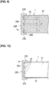
- the impact load that is received by the connecting member 23B will be in a state in which stress is concentrated at the peripheral front end 1a due to the plurality of projections 49, as illustrated in Figure 11 .
- the impact load reaches the side surfaces 37 of the energy-absorbing member 1 for each of the plurality of projections 49, as indicated by the arrows P.
- the energy-absorbing member 1 is torn into multiple pieces along the load input direction with the projections 49 as the points of origin. That is, the projections 49 function as a tearing element that tears the energy-absorbing member 1.
- the connecting member 23B moves in the direction toward the front side members 3 and transitions from the state before the impact load is received shown in Figure 9 , so as to crush the energy-absorbing member 1.
- the energy-absorbing member 1 absorbs the impact by being inwardly displaced as it tears.
- reinforcing fibers 47 indicated by the chain double-dashed lines are arranged in a direction that intersects the load input direction, which is essentially the same direction as that indicated by the arrows P, at an approximately 45° angle, for example, as illustrated in Figure 11 .
- the reinforcing fibers 47 are also severed, thereby absorbing the impact load. As a result, the energy absorption efficiency of the energy-absorbing member 1 is increased.
- the side wall portions 27B of the connecting member 23B are attached so as to cover the outer perimeter side of the energy-absorbing member 1.
- the energy-absorbing member 1 is crushed essentially uniformly over the entire perimeter between the connecting member 23B and the energy-absorbing member, by being displaced inwardly so as to be enveloped by the side wall portions 27B from the outer side at the time of collapse, further enhancing the energy absorption efficiency.
- projections 49 that are integral with the connecting member 23B are provided as the tearing element, instead of the bolts 43 that are used in the first and second embodiments.
- numerous bolts 43, etc. become unnecessary, which correspondingly reduces the parts count and improves the assembly workability.
- the connecting member 23B and the energy-absorbing member 1 are fixed by means of an adhesive, for example, four appropriate peripheral locations may be fixed using bolts and nuts.
- the third embodiment may also be configured such that the side wall portions 27B of the connecting member 23B are inserted into the inner side of the energy-absorbing member 1, in the same manner as shown in Figure 7 of the second embodiment.
- projections that abut the peripheral front end 1a are provided in a portion corresponding to the projecting portions 23Aa of Figure 7 , in front of the peripheral front end 1 a of the energy-absorbing member 1.
- the tearing element constituted by the bolts 43 in the first and second embodiments or the projections 49 in the third embodiment, is provided on the bumper reinforcement 17 side of the energy-absorbing member 1.
- the tearing element can be provided on the side of the energy-absorbing member 1 adjacent the front side members 3, or provided on both the side of the bumper reinforcement 17 and the side of the front side members 3.
- the stud bolts 33 are set in positions corresponding to the bolts 19 in Figure 2 and made to abut the front-end flange 3f of the front side members 3, and the nuts 21 are fastened to the stud bolts 33.
- the energy-absorbing member 1 is not provided with the rear end flange 1f as shown in Figures 2 and 3 , and the shapes of both the front and rear end portions are made the same.
- the attachment structure of the rear end portion of the energy-absorbing member 1 with respect to the front side members 3 is the same as when the tearing element described above is only provided on the side of the front side members 3 of the energy-absorbing member 1.
- the energy-absorbing member 1 is configured to have the form of a quadrangular prism tube, but the shape may be a polygonal shape or a columnar tube shape, other than the form of a quadrangular prism.
- the shapes of the connecting members 23, 23A, 23B are similarly changed in accordance with the shape of the energy-absorbing member 1.
- reinforcing fibers 47 are arranged in a direction that intersects the load input direction, at an angle of approximately 45°, which is essentially the same direction as that indicated by the arrows P, as illustrated in Figures 4 and 11 .
- the angle of intersection is not limited to 45°.
- the reinforcing fibers 47 may intersect the load input direction at a 90° angle, for example. In other words, the reinforcing fibers 47 need only intersect the load input direction in essentially the same direction as that indicated by the arrows P. Because the reinforcing fibers 47 cross the load input direction, the reinforcing fibers are severed by the tearing element.
- the first embodiment, which employs bolts 43, and the third embodiment, which employs projections 49 can be combined.
- the bolts 43 and the projections 49 are prevented from overlapping along the load input direction.
- the bolts 43 in the second embodiment shown in Figure 7 and the projections that are provided in front of the peripheral front end 1a of the energy-absorbing member 1 can be combined as well.
- the present invention is applied to an energy-absorbing structure that uses an energy-absorbing member made of fiber-reinforced resin.
Landscapes
- Engineering & Computer Science (AREA)
- Mechanical Engineering (AREA)
- Vibration Dampers (AREA)
- Body Structure For Vehicles (AREA)
Applications Claiming Priority (1)
| Application Number | Priority Date | Filing Date | Title |
|---|---|---|---|
| PCT/JP2016/062095 WO2017179187A1 (ja) | 2016-04-15 | 2016-04-15 | エネルギ吸収構造 |
Publications (3)
| Publication Number | Publication Date |
|---|---|
| EP3444146A1 true EP3444146A1 (de) | 2019-02-20 |
| EP3444146A4 EP3444146A4 (de) | 2019-02-20 |
| EP3444146B1 EP3444146B1 (de) | 2020-04-08 |
Family
ID=60041520
Family Applications (1)
| Application Number | Title | Priority Date | Filing Date |
|---|---|---|---|
| EP16898647.9A Active EP3444146B1 (de) | 2016-04-15 | 2016-04-15 | Energieabsorptionsstruktur |
Country Status (5)
| Country | Link |
|---|---|
| US (1) | US10710532B2 (de) |
| EP (1) | EP3444146B1 (de) |
| JP (1) | JP6569804B2 (de) |
| CN (1) | CN109070820B (de) |
| WO (1) | WO2017179187A1 (de) |
Families Citing this family (5)
| Publication number | Priority date | Publication date | Assignee | Title |
|---|---|---|---|---|
| JP6581686B1 (ja) * | 2018-03-30 | 2019-09-25 | 株式会社Uacj | バンパー構造体 |
| JP7065689B2 (ja) * | 2018-05-24 | 2022-05-12 | 三菱重工業株式会社 | 衝撃吸収部材、及び緩衝体 |
| FR3116491B1 (fr) * | 2020-11-26 | 2023-03-10 | Valeo Systemes Thermiques | Dispositif absorbeur d’énergie. |
| JP7505510B2 (ja) * | 2022-01-14 | 2024-06-25 | トヨタ自動車株式会社 | 車両構造及び車両の製造方法 |
| CN115370688B (zh) * | 2022-07-25 | 2025-06-20 | 中南大学 | 一种金属圆管的撕裂弯曲式吸能结构 |
Family Cites Families (16)
| Publication number | Priority date | Publication date | Assignee | Title |
|---|---|---|---|---|
| JP3144054B2 (ja) * | 1992-05-28 | 2001-03-07 | 株式会社豊田自動織機製作所 | エネルギー吸収部材 |
| DE4425829C1 (de) * | 1994-07-21 | 1995-10-12 | Daimler Benz Aerospace Ag | Strukturelement im Sandwich-Form |
| DE19623449A1 (de) * | 1996-06-12 | 1998-01-02 | Daimler Benz Ag | Stoßenergie absorbierendes Rohrelement |
| US5914163A (en) * | 1997-10-10 | 1999-06-22 | General Motors Corporation | Reduced crush initiation force composite tube |
| US6601886B1 (en) * | 2002-05-31 | 2003-08-05 | Hexcel Corporation | Energy absorbing composite tube |
| DE10243460A1 (de) * | 2002-09-19 | 2004-04-01 | Rehau Ag + Co. | Polymerer Energieabsorber für Kraftfahrzeuge und Stoßfängersystem |
| NO20032896D0 (no) * | 2003-06-23 | 2003-06-23 | Norsk Hydro As | Energiabsorberende system |
| JP2005247096A (ja) | 2004-03-03 | 2005-09-15 | Nippon Gmt Kk | 車両用衝撃吸収体及び車両用衝撃吸収装置 |
| JP4440683B2 (ja) | 2004-03-26 | 2010-03-24 | 日産自動車株式会社 | 繊維強化プラスチック製エネルギー吸収部材の取付け構造 |
| EP2511141B1 (de) * | 2011-04-13 | 2014-01-22 | Volvo Car Corporation | Aufprallenergieabsobierende Vorrichtung und Verfahren zur Steuerung der bei einem Aufprall auf ein Fahrzeug übertragenen Energie |
| DE102012200410A1 (de) * | 2012-01-12 | 2013-07-18 | Thermoplast Composite Gmbh | Energie absorbierende Tragstruktur sowie Verfahren zur Herstellung von dieser |
| DE102012214751A1 (de) * | 2012-08-20 | 2014-06-05 | Bayerische Motoren Werke Aktiengesellschaft | Fahrzeug |
| WO2014042211A1 (ja) * | 2012-09-13 | 2014-03-20 | 本田技研工業株式会社 | 自動車の車体前部構造 |
| DE102013200678A1 (de) * | 2013-01-17 | 2014-07-17 | Bayerische Motoren Werke Aktiengesellschaft | Energieaufnahmestruktur für ein Fahrzeug |
| JP2015085788A (ja) * | 2013-10-30 | 2015-05-07 | いすゞ自動車株式会社 | 車両の所定部品の支持構造 |
| CN104691467B (zh) * | 2015-01-06 | 2016-11-02 | 华侨大学 | 碰撞复合吸能装置和用途 |
-
2016
- 2016-04-15 WO PCT/JP2016/062095 patent/WO2017179187A1/ja not_active Ceased
- 2016-04-15 US US16/093,159 patent/US10710532B2/en active Active
- 2016-04-15 EP EP16898647.9A patent/EP3444146B1/de active Active
- 2016-04-15 CN CN201680084637.0A patent/CN109070820B/zh active Active
- 2016-04-15 JP JP2018511849A patent/JP6569804B2/ja active Active
Also Published As
| Publication number | Publication date |
|---|---|
| US10710532B2 (en) | 2020-07-14 |
| US20190135210A1 (en) | 2019-05-09 |
| WO2017179187A1 (ja) | 2017-10-19 |
| EP3444146A4 (de) | 2019-02-20 |
| JPWO2017179187A1 (ja) | 2019-02-21 |
| JP6569804B2 (ja) | 2019-09-04 |
| CN109070820A (zh) | 2018-12-21 |
| EP3444146B1 (de) | 2020-04-08 |
| CN109070820B (zh) | 2021-07-06 |
Similar Documents
| Publication | Publication Date | Title |
|---|---|---|
| EP3444146B1 (de) | Energieabsorptionsstruktur | |
| JP5954312B2 (ja) | 車両前部構造 | |
| JP6136187B2 (ja) | 車両用電池搭載構造 | |
| EP3604044B1 (de) | Stossdämpfungselement für fahrzeuge | |
| EP3009307A1 (de) | Vorderkonstruktion einer fahrzeugkarosserie | |
| JP5862555B2 (ja) | 自動車の車体構造 | |
| JP6562064B2 (ja) | 車両の衝撃吸収構造 | |
| CN106585542A (zh) | 带冲击吸收部件的车身构造 | |
| JP2016002817A (ja) | 車両用骨格構造 | |
| JP2015209111A (ja) | 車両前部構造 | |
| CN111629921A (zh) | 冲击吸收部件 | |
| JP6070481B2 (ja) | 接合構造 | |
| KR102699017B1 (ko) | 차량의 전방 바디 | |
| KR20210106010A (ko) | 충격 흡수 부재 | |
| JP6520694B2 (ja) | 車両前部構造 | |
| JP6102817B2 (ja) | 車両後部構造 | |
| KR101374737B1 (ko) | 차량용 도어 충격 흡수부재 | |
| EP3446929A1 (de) | Energieabsorptionsstruktur | |
| JP2018176889A (ja) | バンパリインフォースメント | |
| JP2009286245A (ja) | 車両用フード構造 | |
| KR20240104916A (ko) | 차량의 사이드실 어셈블리 | |
| WO2014097765A1 (ja) | 自動車の車体構造 | |
| JP4973045B2 (ja) | 車両前部構造 | |
| JP6566018B2 (ja) | 車両の衝撃吸収構造 | |
| JP6112002B2 (ja) | 車両カウルサイド構造 |
Legal Events
| Date | Code | Title | Description |
|---|---|---|---|
| STAA | Information on the status of an ep patent application or granted ep patent |
Free format text: STATUS: THE INTERNATIONAL PUBLICATION HAS BEEN MADE |
|
| PUAI | Public reference made under article 153(3) epc to a published international application that has entered the european phase |
Free format text: ORIGINAL CODE: 0009012 |
|
| STAA | Information on the status of an ep patent application or granted ep patent |
Free format text: STATUS: REQUEST FOR EXAMINATION WAS MADE |
|
| 17P | Request for examination filed |
Effective date: 20181113 |
|
| A4 | Supplementary search report drawn up and despatched |
Effective date: 20181217 |
|
| AK | Designated contracting states |
Kind code of ref document: A1 Designated state(s): AL AT BE BG CH CY CZ DE DK EE ES FI FR GB GR HR HU IE IS IT LI LT LU LV MC MK MT NL NO PL PT RO RS SE SI SK SM TR |
|
| AX | Request for extension of the european patent |
Extension state: BA ME |
|
| DAV | Request for validation of the european patent (deleted) | ||
| DAX | Request for extension of the european patent (deleted) | ||
| GRAP | Despatch of communication of intention to grant a patent |
Free format text: ORIGINAL CODE: EPIDOSNIGR1 |
|
| STAA | Information on the status of an ep patent application or granted ep patent |
Free format text: STATUS: GRANT OF PATENT IS INTENDED |
|
| INTG | Intention to grant announced |
Effective date: 20191022 |
|
| GRAS | Grant fee paid |
Free format text: ORIGINAL CODE: EPIDOSNIGR3 |
|
| GRAA | (expected) grant |
Free format text: ORIGINAL CODE: 0009210 |
|
| STAA | Information on the status of an ep patent application or granted ep patent |
Free format text: STATUS: THE PATENT HAS BEEN GRANTED |
|
| AK | Designated contracting states |
Kind code of ref document: B1 Designated state(s): AL AT BE BG CH CY CZ DE DK EE ES FI FR GB GR HR HU IE IS IT LI LT LU LV MC MK MT NL NO PL PT RO RS SE SI SK SM TR |
|
| RAP1 | Party data changed (applicant data changed or rights of an application transferred) |
Owner name: RENAULT S.A.S. Owner name: NISSAN MOTOR CO., LTD. |
|
| REG | Reference to a national code |
Ref country code: CH Ref legal event code: EP Ref country code: AT Ref legal event code: REF Ref document number: 1253961 Country of ref document: AT Kind code of ref document: T Effective date: 20200415 |
|
| REG | Reference to a national code |
Ref country code: DE Ref legal event code: R096 Ref document number: 602016033887 Country of ref document: DE |
|
| REG | Reference to a national code |
Ref country code: IE Ref legal event code: FG4D |
|
| REG | Reference to a national code |
Ref country code: NL Ref legal event code: MP Effective date: 20200408 |
|
| REG | Reference to a national code |
Ref country code: LT Ref legal event code: MG4D |
|
| PG25 | Lapsed in a contracting state [announced via postgrant information from national office to epo] |
Ref country code: NL Free format text: LAPSE BECAUSE OF FAILURE TO SUBMIT A TRANSLATION OF THE DESCRIPTION OR TO PAY THE FEE WITHIN THE PRESCRIBED TIME-LIMIT Effective date: 20200408 Ref country code: SE Free format text: LAPSE BECAUSE OF FAILURE TO SUBMIT A TRANSLATION OF THE DESCRIPTION OR TO PAY THE FEE WITHIN THE PRESCRIBED TIME-LIMIT Effective date: 20200408 Ref country code: FI Free format text: LAPSE BECAUSE OF FAILURE TO SUBMIT A TRANSLATION OF THE DESCRIPTION OR TO PAY THE FEE WITHIN THE PRESCRIBED TIME-LIMIT Effective date: 20200408 Ref country code: GR Free format text: LAPSE BECAUSE OF FAILURE TO SUBMIT A TRANSLATION OF THE DESCRIPTION OR TO PAY THE FEE WITHIN THE PRESCRIBED TIME-LIMIT Effective date: 20200709 Ref country code: NO Free format text: LAPSE BECAUSE OF FAILURE TO SUBMIT A TRANSLATION OF THE DESCRIPTION OR TO PAY THE FEE WITHIN THE PRESCRIBED TIME-LIMIT Effective date: 20200708 Ref country code: IS Free format text: LAPSE BECAUSE OF FAILURE TO SUBMIT A TRANSLATION OF THE DESCRIPTION OR TO PAY THE FEE WITHIN THE PRESCRIBED TIME-LIMIT Effective date: 20200808 Ref country code: LT Free format text: LAPSE BECAUSE OF FAILURE TO SUBMIT A TRANSLATION OF THE DESCRIPTION OR TO PAY THE FEE WITHIN THE PRESCRIBED TIME-LIMIT Effective date: 20200408 Ref country code: PT Free format text: LAPSE BECAUSE OF FAILURE TO SUBMIT A TRANSLATION OF THE DESCRIPTION OR TO PAY THE FEE WITHIN THE PRESCRIBED TIME-LIMIT Effective date: 20200817 |
|
| REG | Reference to a national code |
Ref country code: AT Ref legal event code: MK05 Ref document number: 1253961 Country of ref document: AT Kind code of ref document: T Effective date: 20200408 |
|
| PG25 | Lapsed in a contracting state [announced via postgrant information from national office to epo] |
Ref country code: LV Free format text: LAPSE BECAUSE OF FAILURE TO SUBMIT A TRANSLATION OF THE DESCRIPTION OR TO PAY THE FEE WITHIN THE PRESCRIBED TIME-LIMIT Effective date: 20200408 Ref country code: RS Free format text: LAPSE BECAUSE OF FAILURE TO SUBMIT A TRANSLATION OF THE DESCRIPTION OR TO PAY THE FEE WITHIN THE PRESCRIBED TIME-LIMIT Effective date: 20200408 Ref country code: BG Free format text: LAPSE BECAUSE OF FAILURE TO SUBMIT A TRANSLATION OF THE DESCRIPTION OR TO PAY THE FEE WITHIN THE PRESCRIBED TIME-LIMIT Effective date: 20200708 Ref country code: HR Free format text: LAPSE BECAUSE OF FAILURE TO SUBMIT A TRANSLATION OF THE DESCRIPTION OR TO PAY THE FEE WITHIN THE PRESCRIBED TIME-LIMIT Effective date: 20200408 |
|
| REG | Reference to a national code |
Ref country code: CH Ref legal event code: PL |
|
| PG25 | Lapsed in a contracting state [announced via postgrant information from national office to epo] |
Ref country code: AL Free format text: LAPSE BECAUSE OF FAILURE TO SUBMIT A TRANSLATION OF THE DESCRIPTION OR TO PAY THE FEE WITHIN THE PRESCRIBED TIME-LIMIT Effective date: 20200408 |
|
| REG | Reference to a national code |
Ref country code: DE Ref legal event code: R097 Ref document number: 602016033887 Country of ref document: DE |
|
| PG25 | Lapsed in a contracting state [announced via postgrant information from national office to epo] |
Ref country code: RO Free format text: LAPSE BECAUSE OF FAILURE TO SUBMIT A TRANSLATION OF THE DESCRIPTION OR TO PAY THE FEE WITHIN THE PRESCRIBED TIME-LIMIT Effective date: 20200408 Ref country code: CZ Free format text: LAPSE BECAUSE OF FAILURE TO SUBMIT A TRANSLATION OF THE DESCRIPTION OR TO PAY THE FEE WITHIN THE PRESCRIBED TIME-LIMIT Effective date: 20200408 Ref country code: LU Free format text: LAPSE BECAUSE OF NON-PAYMENT OF DUE FEES Effective date: 20200415 Ref country code: DK Free format text: LAPSE BECAUSE OF FAILURE TO SUBMIT A TRANSLATION OF THE DESCRIPTION OR TO PAY THE FEE WITHIN THE PRESCRIBED TIME-LIMIT Effective date: 20200408 Ref country code: AT Free format text: LAPSE BECAUSE OF FAILURE TO SUBMIT A TRANSLATION OF THE DESCRIPTION OR TO PAY THE FEE WITHIN THE PRESCRIBED TIME-LIMIT Effective date: 20200408 Ref country code: IT Free format text: LAPSE BECAUSE OF FAILURE TO SUBMIT A TRANSLATION OF THE DESCRIPTION OR TO PAY THE FEE WITHIN THE PRESCRIBED TIME-LIMIT Effective date: 20200408 Ref country code: SM Free format text: LAPSE BECAUSE OF FAILURE TO SUBMIT A TRANSLATION OF THE DESCRIPTION OR TO PAY THE FEE WITHIN THE PRESCRIBED TIME-LIMIT Effective date: 20200408 Ref country code: EE Free format text: LAPSE BECAUSE OF FAILURE TO SUBMIT A TRANSLATION OF THE DESCRIPTION OR TO PAY THE FEE WITHIN THE PRESCRIBED TIME-LIMIT Effective date: 20200408 Ref country code: ES Free format text: LAPSE BECAUSE OF FAILURE TO SUBMIT A TRANSLATION OF THE DESCRIPTION OR TO PAY THE FEE WITHIN THE PRESCRIBED TIME-LIMIT Effective date: 20200408 Ref country code: LI Free format text: LAPSE BECAUSE OF NON-PAYMENT OF DUE FEES Effective date: 20200430 Ref country code: MC Free format text: LAPSE BECAUSE OF FAILURE TO SUBMIT A TRANSLATION OF THE DESCRIPTION OR TO PAY THE FEE WITHIN THE PRESCRIBED TIME-LIMIT Effective date: 20200408 Ref country code: CH Free format text: LAPSE BECAUSE OF NON-PAYMENT OF DUE FEES Effective date: 20200430 |
|
| REG | Reference to a national code |
Ref country code: BE Ref legal event code: MM Effective date: 20200430 |
|
| PLBE | No opposition filed within time limit |
Free format text: ORIGINAL CODE: 0009261 |
|
| STAA | Information on the status of an ep patent application or granted ep patent |
Free format text: STATUS: NO OPPOSITION FILED WITHIN TIME LIMIT |
|
| PG25 | Lapsed in a contracting state [announced via postgrant information from national office to epo] |
Ref country code: PL Free format text: LAPSE BECAUSE OF FAILURE TO SUBMIT A TRANSLATION OF THE DESCRIPTION OR TO PAY THE FEE WITHIN THE PRESCRIBED TIME-LIMIT Effective date: 20200408 Ref country code: SK Free format text: LAPSE BECAUSE OF FAILURE TO SUBMIT A TRANSLATION OF THE DESCRIPTION OR TO PAY THE FEE WITHIN THE PRESCRIBED TIME-LIMIT Effective date: 20200408 Ref country code: BE Free format text: LAPSE BECAUSE OF NON-PAYMENT OF DUE FEES Effective date: 20200430 |
|
| 26N | No opposition filed |
Effective date: 20210112 |
|
| PG25 | Lapsed in a contracting state [announced via postgrant information from national office to epo] |
Ref country code: IE Free format text: LAPSE BECAUSE OF NON-PAYMENT OF DUE FEES Effective date: 20200415 |
|
| PG25 | Lapsed in a contracting state [announced via postgrant information from national office to epo] |
Ref country code: SI Free format text: LAPSE BECAUSE OF FAILURE TO SUBMIT A TRANSLATION OF THE DESCRIPTION OR TO PAY THE FEE WITHIN THE PRESCRIBED TIME-LIMIT Effective date: 20200408 |
|
| PG25 | Lapsed in a contracting state [announced via postgrant information from national office to epo] |
Ref country code: TR Free format text: LAPSE BECAUSE OF FAILURE TO SUBMIT A TRANSLATION OF THE DESCRIPTION OR TO PAY THE FEE WITHIN THE PRESCRIBED TIME-LIMIT Effective date: 20200408 Ref country code: MT Free format text: LAPSE BECAUSE OF FAILURE TO SUBMIT A TRANSLATION OF THE DESCRIPTION OR TO PAY THE FEE WITHIN THE PRESCRIBED TIME-LIMIT Effective date: 20200408 Ref country code: CY Free format text: LAPSE BECAUSE OF FAILURE TO SUBMIT A TRANSLATION OF THE DESCRIPTION OR TO PAY THE FEE WITHIN THE PRESCRIBED TIME-LIMIT Effective date: 20200408 |
|
| PG25 | Lapsed in a contracting state [announced via postgrant information from national office to epo] |
Ref country code: MK Free format text: LAPSE BECAUSE OF FAILURE TO SUBMIT A TRANSLATION OF THE DESCRIPTION OR TO PAY THE FEE WITHIN THE PRESCRIBED TIME-LIMIT Effective date: 20200408 |
|
| PGFP | Annual fee paid to national office [announced via postgrant information from national office to epo] |
Ref country code: DE Payment date: 20250319 Year of fee payment: 10 |
|
| PGFP | Annual fee paid to national office [announced via postgrant information from national office to epo] |
Ref country code: GB Payment date: 20260319 Year of fee payment: 11 |
|
| PGFP | Annual fee paid to national office [announced via postgrant information from national office to epo] |
Ref country code: FR Payment date: 20260320 Year of fee payment: 11 |