EP3444549A1 - Wurfblech und trocknungseinheit mit mehreren derartigen wurfblechen - Google Patents
Wurfblech und trocknungseinheit mit mehreren derartigen wurfblechen Download PDFInfo
- Publication number
- EP3444549A1 EP3444549A1 EP18167705.5A EP18167705A EP3444549A1 EP 3444549 A1 EP3444549 A1 EP 3444549A1 EP 18167705 A EP18167705 A EP 18167705A EP 3444549 A1 EP3444549 A1 EP 3444549A1
- Authority
- EP
- European Patent Office
- Prior art keywords
- throwing
- drying unit
- rotation
- axis
- plates
- Prior art date
- Legal status (The legal status is an assumption and is not a legal conclusion. Google has not performed a legal analysis and makes no representation as to the accuracy of the status listed.)
- Granted
Links
Images


Classifications
-
- F—MECHANICAL ENGINEERING; LIGHTING; HEATING; WEAPONS; BLASTING
- F27—FURNACES; KILNS; OVENS; RETORTS
- F27B—FURNACES, KILNS, OVENS OR RETORTS IN GENERAL; OPEN SINTERING OR LIKE APPARATUS
- F27B7/00—Rotary-drum furnaces, i.e. horizontal or slightly inclined
- F27B7/14—Rotary-drum furnaces, i.e. horizontal or slightly inclined with means for agitating or moving the charge
- F27B7/16—Rotary-drum furnaces, i.e. horizontal or slightly inclined with means for agitating or moving the charge the means being fixed relatively to the drum, e.g. composite means
- F27B7/161—Rotary-drum furnaces, i.e. horizontal or slightly inclined with means for agitating or moving the charge the means being fixed relatively to the drum, e.g. composite means the means comprising projections jutting out from the wall
-
- F—MECHANICAL ENGINEERING; LIGHTING; HEATING; WEAPONS; BLASTING
- F26—DRYING
- F26B—DRYING SOLID MATERIALS OR OBJECTS BY REMOVING LIQUID THEREFROM
- F26B11/00—Machines or apparatus for drying solid materials or objects with movement which is non-progressive
- F26B11/02—Machines or apparatus for drying solid materials or objects with movement which is non-progressive in moving drums or other mainly-closed receptacles
- F26B11/04—Machines or apparatus for drying solid materials or objects with movement which is non-progressive in moving drums or other mainly-closed receptacles rotating about a horizontal or slightly-inclined axis
- F26B11/0404—Machines or apparatus for drying solid materials or objects with movement which is non-progressive in moving drums or other mainly-closed receptacles rotating about a horizontal or slightly-inclined axis with internal subdivision of the drum, e.g. for subdividing or recycling the material to be dried
- F26B11/0409—Machines or apparatus for drying solid materials or objects with movement which is non-progressive in moving drums or other mainly-closed receptacles rotating about a horizontal or slightly-inclined axis with internal subdivision of the drum, e.g. for subdividing or recycling the material to be dried the subdivision consisting of a plurality of substantially radially oriented internal walls, e.g. forming multiple sector-shaped chambers
-
- F—MECHANICAL ENGINEERING; LIGHTING; HEATING; WEAPONS; BLASTING
- F26—DRYING
- F26B—DRYING SOLID MATERIALS OR OBJECTS BY REMOVING LIQUID THEREFROM
- F26B23/00—Heating arrangements
- F26B23/02—Heating arrangements using combustion heating
-
- F—MECHANICAL ENGINEERING; LIGHTING; HEATING; WEAPONS; BLASTING
- F26—DRYING
- F26B—DRYING SOLID MATERIALS OR OBJECTS BY REMOVING LIQUID THEREFROM
- F26B3/00—Drying solid materials or objects by processes involving the application of heat
- F26B3/02—Drying solid materials or objects by processes involving the application of heat by convection, i.e. heat being conveyed from a heat source to the materials or objects to be dried by a gas or vapour, e.g. air
- F26B3/04—Drying solid materials or objects by processes involving the application of heat by convection, i.e. heat being conveyed from a heat source to the materials or objects to be dried by a gas or vapour, e.g. air the gas or vapour circulating over or surrounding the materials or objects to be dried
-
- F—MECHANICAL ENGINEERING; LIGHTING; HEATING; WEAPONS; BLASTING
- F27—FURNACES; KILNS; OVENS; RETORTS
- F27B—FURNACES, KILNS, OVENS OR RETORTS IN GENERAL; OPEN SINTERING OR LIKE APPARATUS
- F27B7/00—Rotary-drum furnaces, i.e. horizontal or slightly inclined
- F27B7/14—Rotary-drum furnaces, i.e. horizontal or slightly inclined with means for agitating or moving the charge
- F27B7/16—Rotary-drum furnaces, i.e. horizontal or slightly inclined with means for agitating or moving the charge the means being fixed relatively to the drum, e.g. composite means
- F27B7/161—Rotary-drum furnaces, i.e. horizontal or slightly inclined with means for agitating or moving the charge the means being fixed relatively to the drum, e.g. composite means the means comprising projections jutting out from the wall
- F27B7/162—Rotary-drum furnaces, i.e. horizontal or slightly inclined with means for agitating or moving the charge the means being fixed relatively to the drum, e.g. composite means the means comprising projections jutting out from the wall the projections consisting of separate lifting elements, e.g. lifting shovels
-
- F—MECHANICAL ENGINEERING; LIGHTING; HEATING; WEAPONS; BLASTING
- F27—FURNACES; KILNS; OVENS; RETORTS
- F27B—FURNACES, KILNS, OVENS OR RETORTS IN GENERAL; OPEN SINTERING OR LIKE APPARATUS
- F27B7/00—Rotary-drum furnaces, i.e. horizontal or slightly inclined
- F27B7/02—Rotary-drum furnaces, i.e. horizontal or slightly inclined of multiple-chamber or multiple-drum type
- F27B7/04—Rotary-drum furnaces, i.e. horizontal or slightly inclined of multiple-chamber or multiple-drum type with longitudinal divisions
- F27B2007/046—Radial partitions
-
- F—MECHANICAL ENGINEERING; LIGHTING; HEATING; WEAPONS; BLASTING
- F27—FURNACES; KILNS; OVENS; RETORTS
- F27B—FURNACES, KILNS, OVENS OR RETORTS IN GENERAL; OPEN SINTERING OR LIKE APPARATUS
- F27B7/00—Rotary-drum furnaces, i.e. horizontal or slightly inclined
- F27B7/14—Rotary-drum furnaces, i.e. horizontal or slightly inclined with means for agitating or moving the charge
- F27B7/16—Rotary-drum furnaces, i.e. horizontal or slightly inclined with means for agitating or moving the charge the means being fixed relatively to the drum, e.g. composite means
- F27B7/161—Rotary-drum furnaces, i.e. horizontal or slightly inclined with means for agitating or moving the charge the means being fixed relatively to the drum, e.g. composite means the means comprising projections jutting out from the wall
- F27B7/162—Rotary-drum furnaces, i.e. horizontal or slightly inclined with means for agitating or moving the charge the means being fixed relatively to the drum, e.g. composite means the means comprising projections jutting out from the wall the projections consisting of separate lifting elements, e.g. lifting shovels
- F27B2007/163—Rotary-drum furnaces, i.e. horizontal or slightly inclined with means for agitating or moving the charge the means being fixed relatively to the drum, e.g. composite means the means comprising projections jutting out from the wall the projections consisting of separate lifting elements, e.g. lifting shovels using only a ring of lifting elements to lift the charge
Definitions
- the invention relates to a throwing plate and a drying unit with a plurality of such throwing sheets.
- a drying unit in the form of a rotary kiln is used for example in plants for the production of asphalt.
- a rotary kiln is from the GB 1 396 402 A known.
- the rotary kiln is used for heating and mixing old asphalt granulate, so-called recycled (RC) material.
- the material is conveyed during drying and heating by the drying unit, which rotates about a longitudinal axis. This will mix the material.
- the material adheres to the inside of the drying unit, in particular to throwing sheets.
- caking There are so-called caking.
- the material is affected on the inside of the drying unit and on the throwing sheets. The caking in particular hinder the flow of material in the drying unit. The caking ultimately leads to malfunction of the drying unit.
- the US 2016136597 A1 discloses a mixing unit for preventing segregation.
- the invention has for its object to improve the heating of material in a drying unit.
- a throwing sheet having the features of claim 1.
- the essence of the invention consists in that a throwing plate has an edge-free contour in a plane oriented perpendicularly to a material-throwing-sheet conveying direction. According to the invention, it was found that the cause of caking on conventional throwing sheets was due to edges of the throwing sheets. The fact that the throwing plate has an edge-free contour, the risk of caking is reduced and especially excluded.
- the throwing plate is used for a drying unit, which can be used in particular in a plant for the production of asphalt, in particular for drying and heating of Altasphaltmaterial in countercurrent or DC process.
- a material throwing sheet conveying direction the direction is understood, along which the material is conveyed by means of the throwing plate.
- the material throwing sheet conveying direction is independent of the orientation of the throwing sheet in the drying unit.
- the throwing plate is designed in the plane oriented perpendicular to the material throwing sheet conveying direction, in particular with an uneven contour.
- the throwing sheet acts in particular as a bulk material chute along which the material throwing-sheet conveying direction is predetermined.
- the bulk material channel By means of the bulk material channel, the material can be selectively supplied to another bulk material channel.
- the bulk material gutters are arranged axially offset from one another.
- a contour of the throwing plate according to claim 2 ensures a trouble-free material transport.
- the throwing plate allows in particular targeted collection and / or collection of material, in particular from a preceding throwing sheet.
- a throwing sheet with a semicircular contour is thus designed in the shape of a half cylinder shell.
- Such a throwing plate can be made particularly uncomplicated, for example, by a cylinder tube is separated along the longitudinal axis.
- the contour of a throwing sheet according to claim 3 enables uncomplicated and cost-effective production, especially in large quantities of the throwing sheet.
- the throwing plate can be made directly from a cylinder tube.
- the conveying conditions for the material during the conveyance along the material throwing sheet conveying direction are constant.
- a drying unit according to claim 4 with a plurality of throwing sheets essentially has the advantages of the throwing sheets themselves.
- the drying unit is designed in particular as a drying drum and serves for drying and / or heating of the material for the production of asphalt.
- the drying drum with the throwing sheets guarantees a reliable and trouble-free heating of the material.
- the drying unit has a hollow cylindrical housing, which is also referred to as a drum.
- the drum is rotatably driven about its axis of rotation.
- the throwing plates are attached.
- the throwing sheets are arranged in the housing such that the material throwing sheet conveying direction is oriented in each case transversely to the axis of rotation.
- the material sheet conveying direction has a directional portion which is oriented radially to the axis of rotation.
- the throwing plates are oriented with the material throwing sheet conveying direction perpendicular to the axis of rotation.
- the throwing plates form cylindrical half-shell-shaped chutes through which the material is poured around the longitudinal axis as a result of the rotation of the housing and passes into the next throwing plate.
- the litter sheets are used in particular for targeted material delivery within the drying unit.
- the material is prevented by the throwing plates to fall automatically due to gravity uncontrollably on the subsequent throwing sheet.
- the litter plates force a guided material conveyance along the material lapping conveyor direction. The material falls due to gravity on or in a subsequent throwing sheet when the material has passed through the oriented in material throw plate conveying direction end.
- An adjustment of the inclination angle of the throwing plates relative to the axis of rotation of the housing according to claim 5 allows influencing the Ausg cash s of the material.
- the smaller the angle of inclination is selected the sooner the material to be heated is poured out of the throwing plate into the next throwing plate when the housing is rotated.
- the pouring behavior of the material changes.
- the material veil is to be understood as optimal in the context of the application, when the material veil covers the inner surface along the circumference of the drum as evenly as possible during the rotation of the drum. This improves heat transfer from the drum to the material.
- the material veil has gaps along the circumference, ie the inner surface of the drum remains free in regions and is not covered with material in these areas, the heat can not be transferred to the material in these free areas or only to a limited extent. This leads to increased exhaust gas temperatures and to a reduced material temperature. The efficiency of material heating would be reduced. The improved material veil enhances the material heating efficiency improved.
- the material throwing sheet conveying direction is oriented perpendicular to the axis of rotation.
- a drying unit according to claim 6 has a better mixing ratio.
- the staggered arrangement of the launcher layers according to claim 8 was determined as a particularly advantageous distance between the laths of different Throwblechlagen.
- caking is prevented from occurring in the particularly critical area of the drying unit.
- the material temperature is typically between 60 ° Celsius and 90 ° Celsius.
- the material to be dried is fed to the drying unit.
- the material In the inlet area, the material is still free-flowing. Caking practically does not occur.
- the material In a hot region downstream of the plasticization zone, the material is heated so that the material becomes approximately molten and begins to flow. The risk of caking is reduced in this material condition.
- the plastication area is arranged along the axis of rotation in the material conveying direction between the inlet area and the warm area.
- FIG. 1 An in Fig. 1 schematically illustrated drying unit 1 is used for drying and / or heating of material, in particular Altasphaltmaterial for asphalt production.
- the drying unit 1 is part of a plant, not shown, for the production of asphalt.
- the drying unit 1 is also called a drying drum.
- the drying unit 1 has a hollow cylindrical housing 2, which is also referred to as a drum.
- the housing 2 is rotatably driven about a rotation axis 3 by means of a drive 4.
- the rotation axis 3 is inclined with respect to a horizontal 40 with an inclination angle h.
- the angle of inclination h is 3 °.
- the angle of inclination h is advantageously set between 1 ° and 10 ° and in particular between 2 ° and 5 °. By varying the angle of inclination h, the material conveying speed can be adjusted in a targeted manner.
- a heat source 5 is arranged in the form of a burner. The heat is supplied by means of the burner 5, starting from the first end wall 11 of the housing. 2
- a material inlet 6 is arranged, by means of which the material to be heated and / or to be dried is supplied to the housing 2.
- a material outlet 7 is provided, via which the heated material can be removed from the drying unit 1 and transported further by means of an arbitrary conveyor 8.
- a material conveying direction 9 is fixed, which is oriented parallel to the axis of rotation 3. Opposite to the material conveying direction 9, the heat supply direction 10 is oriented.
- the drying unit 1 is operated in countercurrent process.
- Fig. 2 shows a settlement of the inside of the housing 2. That means that the hollow cylindrical housing 2 is cut along a generatrix parallel to the axis of rotation 3 and shown in a plane.
- the second end wall 12 on which the material inlet 6 is arranged, shown on the left. Accordingly, the first end wall 11 is opposite in FIG Fig. 2 shown on the right.
- the direction of rotation, with which the housing 2 rotates about the axis of rotation 3, is symbolized by the arrow 13.
- the drying unit 1 has three areas. Facing the second end wall 12 is an inlet region 14. A hot region 15 faces the first end wall 11. Between the inlet region 14 and the warm region 15, a plastication region 16 is arranged along the axis of rotation 3. Along the material conveying direction 9, first the inlet area 14, then the plasticizing area 16 and then the warm area 15 are arranged.
- the inlet region 14 has a first cone section 17, which is composed of nine interconnected cone segments 18.
- the first cone section 17 is designed to widen conically along the material conveying direction 9.
- the smaller cross-sectional area of the cone which is oriented perpendicular to the axis of rotation 3, is arranged on the second end wall 12 and serves as a mouth opening for the drum.
- the first cone section 17 is followed by a protective section 19.
- a plurality, in particular eighteen drum saver 21 are arranged on the inside of the Schonabitess 19 .
- the drum saver 21 are designed as elongated plates which have along their longitudinal axis at the center line a survey. The survey is carried out by a kink at the midline.
- the drum saver 21 additionally attached flat iron. This prevents the Altasphaltmaterial comes into direct contact with the drying drum.
- the drum saver 21 protect the inside of the Schonabitess 19 of the drying unit 1 from wear. The service life of the drying unit 1 is thereby increased.
- the drum saver 21 can be removed and replaced when worn. The replacement of the entire drying unit, which is complicated and expensive, is thereby avoided.
- the positive mixing sections 20 are made substantially identical.
- eight positive linear plates 22 are arranged in each case.
- the positive linear plates 22 are used for mixing the material supplied in the drying unit 1.
- the positive linear plates 22 serve as throwing sheets for substantially not yet plasticized material.
- the positive linear plates 22 are designed as flat sheet metal sections which are fastened with a wall distance on the inside of the housing 2.
- the wall distance is in particular between 20 mm and 100 mm, in particular between 40 mm and 80 mm and in particular about 60 mm.
- the positive linear plates 22 are each arranged with a positive angle of attack a p with respect to the axis of rotation 3.
- the positive angle of attack a p is according to the embodiment shown 10 °.
- the positive angle of attack a p can be between 0 ° and 20 °, in particular between 5 ° and 15 °.
- the inclination of the positive linear plates 22 is oriented in the material conveying direction 9, so that material disposed on the positive linear plate 22 is automatically conveyed in the material conveying direction 9 due to the inclining force on the positive linear plate 22 due to gravity.
- the positive linear plates 22 of a positive mixing section 20 are arranged at equal intervals along the inner circumference of the housing 2. It is also possible to arrange individual positive linear plates 22 with an irregular spacing with respect to the other positive linear plates 22, so that the intermediate area between two adjacent positive linear plates 22 is made different in size.
- the positive mixing sections 20 are designed essentially identically, in particular with an identical number of positive linear plates 22 and identical positive angle of attack a p .
- the positive linear plates 22 of adjacent positive mixing sections 20 are offset relative to one another with respect to the direction of rotation of the axis of rotation 3. As a result, material conveyed from one positive linear plate 22 of the upstream positive mixing section 20 in the material direction 9 can reach the next positive linear plate 22 of the downstream positive mixing section 20. The material delivery is thereby improved.
- the warm area 15 has two negative mixing sections 23.
- the negative mixing portions 23 are made similar to the positive mixing portions 20.
- the negative mixing sections 23 have negative linear plates 24, which are arranged inclined at a negative angle of attack of -10 ° with respect to the axis of rotation.
- the negative linear plates 24 are disposed within a negative mixing portion 23 equidistantly along the rotational direction about the rotation axis 3.
- the negative linear plates 24 of the adjacent negative mixing sections 23 are arranged offset relative to one another with respect to the direction of rotation about the axis of rotation 3.
- the negative linear plates 24 are arranged at a radial distance to the inside of the drying unit 1.
- the radial distance is about 40 mm to 100 mm, in particular 50 mm to 90 mm and in particular 60 mm to 80 mm.
- Material having a grain size smaller than the radial distance passes through the gap formed between the negative linear plate 24 and the drying unit 1 due to the radial clearance, and is conveyed against the horizontal 40 due to the inclination of the drying unit 1.
- Material conglomerates which are larger than the radial distance are promoted by the negative angle of attack against the material conveying direction 9 back into the plastication section 16 and further heated. As a result of further heating, the material conglomerates split.
- the divided material conglomerates can leave the drying unit 1 only along the material conveying direction 9, if their size is smaller than the radial distance.
- the radial distance defines a maximum grain size for the material that can leave the drying unit 1. This prevents the material conglomerates of larger diameter from leaving the drying unit 1. For large material conglomerates sufficient heating can not be guaranteed. Material conglomerates, which are not heated to the core, can cause quality losses, in particular in the form of voids, in a subsequent mixing process. The arrangement of the negative linear plates 24 with the radial distance such quality losses are excluded. The quality of the material heated in the drying unit 1 is increased. Downstream of the material conveying direction 9, a further protective section 25 is provided in the negative mixing sections 23, which extends to the first end wall 11. The Schonabites 25 is performed substantially identical to the Schonabêt 19 and has eighteen drum saver 21. The axial length of the protective section 25 is reduced with respect to the axial length of the protective section 19.
- the plastication region 16 has eight, essentially identically designed, plasticizing sections 26. Each plasticizing section 26 has several according to the illustrated embodiment 8, throw plates 27. The throwing plates 27 within a plasticizing section 26 are fixed along the direction of rotation 13 equidistant to the inside of the housing 2. The lintels 27 within a plasticizing section 26 form an annular lath sheet.
- the Turfblechlagen are each performed substantially identical, wherein along the material conveying direction 9 adjacent Turfblechlagen are offset from one another.
- the offset along the direction of rotation 13 between the throwing sheets 27 of adjacent throwing sheet layers can be determined essentially as desired. It has proven to be particularly advantageous that the offset is set in such a way that the arrangement of the first and the fifth sheet metal layers along the material direction 9 is again identical. Accordingly, the second and the sixth Throwblechlage, the third and the seventh Throwblechlage and the fourth and the eighth Throwblechlage are identical with respect to their relative position along the direction of rotation 13 arranged.
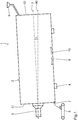
- Fig. 3 to 5 the structure and the arrangement of the throwing plates 27 on the inside of the housing 2 explained in more detail.
- 2 fastening elements 28 are provided on the inside of the housing.
- the fastening elements 28 are in particular welded to the inside of the housing 2.
- a throwing plate 27 in particular two identically designed fastening elements 28 are provided, which are along the axis of rotation 3, that is in a direction perpendicular to the plane of the Fig. 4 are arranged in alignment.
- the fasteners 28 are designed as metal strips.
- the fastening elements 28 have a pivot bore 29 into which a pivot pin 30 is inserted.
- the fastening elements 28 also each have a guide bore 31 into which a guide pin 32 is inserted.
- the pivot pin 30 defines a pivot axis 33 which extends parallel to the axis of rotation 3.
- the guide pin 32 is oriented along the axis of rotation 3.
- the mounting plate 34 is designed as a metal strip and has a pivot receiving bore 35 into which the pivot pin 30 protrudes.
- the mounting plate 34 has a slot-like guide recess 36.
- the guide recess 36 is executed in a circular arc with respect to the pivot axis 33.
- the guide pin 32 projects into the guide recess 36.
- the mounting plate 34 and the fastener 28 are adjacent along the axis of rotation 3, in particular adjacent to each other, arranged.
- the diameter of the guide pin 32 substantially corresponds to the width of the guide recess 36.
- the throw plates 27 are each inclined at an angle n of 15 ° relative to the radial direction 37.
- the inclination angle n is maximum. This can be seen from the fact that the guide pin 32 is disposed at the respective right end of the guide recess 36. Further pivoting of the throwing plate 27 towards larger angles of inclination n is mechanically blocked. The end of the guide recess 36 forms a mechanical stop. In this arrangement, the throwing plate 27 is positioned in an end position. The throwing plate 27 is in a stable arrangement.
- the maximum angle of inclination can also be greater than 15 °.
- the throwing plates 27 are arranged with a rotational angle spacing w, which in particular is identical for all throwing plates 27.
- the angular distance w can also vary.
- the guide pin 32 is designed such that any inclination angle between 0 ° and the maximum inclination angle, here 15 °, can be locked continuously.
- the guide pin 32 spring loaded and / or be designed as a threaded bolt, which is locked with a fastening and an additional lock nut on a rear side of the mounting plate 34.
- the mounting plate 34 and the fastening element 28 are clamped, so that unintentional tilting of the throwing plates 27, in particular during operation of the drying unit 1, is precluded.
- the throwing plates 27 In order to enable collision-free pivoting of the throwing plates 27, they have a chamfer 38 on one of the inside of the housing 2 facing end face.
- the throwing plates 27 each define a material throwing sheet conveying direction 39, which is inclined in particular according to the angle of inclination n with respect to the radial direction 37.
- the throwing plate 27 has a semicircular contour.
- the throwing plate 27 is designed as a cylinder half-shell.
- the throwing plate 27 has a concavely curved surface, so that the material can be conveyed along the material throwing sheet conveying direction 39 unhindered and in particular along an edge-free contour. The risk of caking is reduced.
- the cylindrical half-shell-shaped throwing plates 27 each have a throwing plate diameter Dw, which in the exemplary embodiment shown is between 375 mm and 500 mm. Two shells according to the invention can replace a classic installation.
- the throwing plates 27 have a throwing plate height Hw which, according to the embodiment shown, is between 200 mm and 600 mm.
- the throw plate height Hw also depends on the inner diameter of the drying unit 1, which is between 2000 mm and 3000 mm according to the embodiment shown.
- the operation of the drying unit 1 will be explained in more detail below.
- the housing 2 of the drying unit 1 is rotationally driven about the rotation axis 3 by means of the drive 4.
- the axis of rotation 3 of the drying unit 1 is arranged in particular inclined relative to the horizontal, wherein the inclination is carried out sloping in particular from the material inlet 6 to the material outlet 7.
- the material promotion along the material conveying direction 9, in particular the superposition with the rotary movement of the housing 2 favors.
- the material is slightly heated. In the area the material is still free-flowing. Caking practically does not occur.
- the material is heated to a critical temperature, which is in particular in Altasphaltgranulat between 60 ° C and 90 ° C. Due to the heating of the material and its material properties, it becomes sticky and tends to build up. The material falls from a throwing sheet 27 of a throwing sheet layer into a throwing sheet 27 of the next, downstream arranged throwing sheet layer. Due to the fact that the throwing plates 27 have an edge-free contour, the plasticized material, in spite of its tendency to stick, is moved along the direction of the material-conveying sheet conveying direction 39 promoted substantially without caking along the throwing plate 27.
- a critical temperature which is in particular in Altasphaltgranulat between 60 ° C and 90 ° C. Due to the heating of the material and its material properties, it becomes sticky and tends to build up. The material falls from a throwing sheet 27 of a throwing sheet layer into a throwing sheet 27 of the next, downstream arranged throwing sheet layer. Due to the fact that the throwing plates 27 have an edge-free contour, the plasticized material, in spite of its
- the material conveying speed within the drum can be influenced. This makes it possible to adjust the material properties of the heated material targeted.
Landscapes
- Engineering & Computer Science (AREA)
- Mechanical Engineering (AREA)
- General Engineering & Computer Science (AREA)
- Life Sciences & Earth Sciences (AREA)
- Sustainable Development (AREA)
- Microbiology (AREA)
- Chemical & Material Sciences (AREA)
- Combustion & Propulsion (AREA)
- Drying Of Solid Materials (AREA)
- Road Paving Machines (AREA)
- Processing And Handling Of Plastics And Other Materials For Molding In General (AREA)
Abstract
Description
- Der Inhalt der deutschen Patentanmeldung
DE 10 2017 214 234.0 wird durch Bezugnahme hierin aufgenommen. - Die Erfindung betrifft ein Wurfblech und eine Trocknungseinheit mit mehreren derartigen Wurfblechen.
- Eine Trocknungseinheit in Form eines Drehrohrofens wird beispielsweise in Anlagen zur Herstellung von Asphalt eingesetzt. Ein Drehrohrofen ist aus der
GB 1 396 402 A - Die
US 2016136597 A1 offenbart eine Mischeinheit zur Verhinderung von Segregationen. - Der Erfindung liegt die Aufgabe zugrunde, die Erwärmung von Material in einer Trocknungseinheit zu verbessern.
- Diese Aufgabe ist durch ein Wurfblech mit den Merkmalen des Anspruchs 1 gelöst. Der Kern der Erfindung besteht darin, dass ein Wurfblech in einer senkrecht zu einer Materialwurfblechförderrichtung orientierten Ebene eine kantenfreie Kontur aufweist. Erfindungsgemäß wurde gefunden, dass die Ursache für Anbackungen an herkömmlichen Wurfblechen auf Kanten der Wurfbleche zurückzuführen war. Dadurch, dass das Wurfblech eine kantenfreie Kontur aufweist, ist das Risiko von Anbackungen reduziert und insbesondere ausgeschlossen. Das Wurfblech dient für eine Trocknungseinheit, die insbesondere in einer Anlage zur Asphaltherstellung, insbesondere zum Trocknen und Erwärmen von Altasphaltmaterial im Gegenstrom- oder im Gleichstrom-Verfahren eingesetzt werden kann. Als Materialwurfblechförderrichtung wird die Richtung verstanden, entlang der das Material mittels des Wurfblechs gefördert wird. Insbesondere ist die Materialwurfblechförderrichtung unabhängig von der Orientierung des Wurfblechs in der Trocknungseinheit. Das Wurfblech ist in der senkrecht zur Materialwurfblechförderrichtung orientierten Ebene insbesondere mit einer unebenen Kontur ausgeführt. Das Wurfblech fungiert insbesondere als Schüttgutrinne entlang der die Materialwurfblechförderrichtung vorgegeben ist. Mittels der Schüttgutrinne kann das Material gezielt einer anderen Schüttgutrinne zugeführt werden. In axialer Richtung bezogen auf die Drehachse der Trocknungseinheit ist ein Weitertransport des Materials dadurch möglich, dass die Schüttgutrinnen axial versetzt zueinander angeordnet sind.
- Eine Kontur des Wurfblechs gemäß Anspruch 2 gewährleistet einen störungsfreien Materialtransport. Dadurch, dass die Kontur konkav ausgeführt ist, ist eine gezielte Materialförderung möglich. Das Wurfblech ermöglicht insbesondere ein gezieltes Auffangen und/oder Sammeln von Material, insbesondere aus einem vorangehenden Wurfblech. Ein Wurfblech mit halbkreisförmiger Kontur ist also zylinderhalbschalenförmig ausgeführt. Ein derartiges Wurfblech kann besonders unkompliziert hergestellt werden, indem beispielsweise ein Zylinderrohr entlang der Längsachse getrennt wird.
- Die Kontur eines Wurfblechs gemäß Anspruch 3 ermöglicht eine unkomplizierte und kostengünstige Fertigung, insbesondere bei großen Stückzahlen des Wurfblechs. Das Wurfblech kann unmittelbar aus einem Zylinderrohr hergestellt werden. Die Förderbedingungen für das Material bei der Förderung entlang der Materialwurfblechförderrichtung sind konstant.
- Eine Trocknungseinheit gemäß Anspruch 4 mit mehreren Wurfblechen weist im Wesentlichen die Vorteile der Wurfbleche selbst auf. Die Trocknungseinheit ist insbesondere als Trockentrommel ausgeführt und dient zum Trocknen und/oder Erwärmen des Materials für die Asphaltherstellung. Die Trockentrommel mit den Wurfblechen garantiert eine zuverlässige und störungsfreie Materialerwärmung. Die Trocknungseinheit weist ein hohlzylindrisches Gehäuse auf, das auch als Trommel bezeichnet wird. Die Trommel ist um ihre Drehachse drehantreibbar. In dem Gehäuse sind die Wurfbleche befestigt. Die Wurfbleche sind in dem Gehäuse derart angeordnet, dass die Materialwurfblechförderrichtung jeweils quer zur Drehachse orientiert ist. Die Materialwurfblechförderrichtung weist einen Richtungsanteil auf, der radial zur Drehachse orientiert ist. Insbesondere sind die Wurfbleche mit der Materialwurfblechförderrichtung senkrecht zur Drehachse orientiert. Die Wurfbleche bilden zylinderhalbschalenförmige Schüttrinnen, durch die das Material infolge der Drehung des Gehäuses um die Längsachse geschüttet wird und in das nächste Wurfblech gelangt.
- Die Wurfbleche dienen insbesondere zur gezielten Materialförderung innerhalb der Trocknungseinheit. Insbesondere ist das Material durch die Wurfbleche gehindert, selbsttätig infolge der Schwerkraft unkontrolliert auf das nachfolgende Wurfblech zu fallen. Die Wurfbleche erzwingen eine geführte Materialförderung entlang der Materialwurfblechförderrichtung. Das Material fällt infolge der Schwerkraft auf bzw. in ein nachfolgendes Wurfblech, wenn das Material das in Materialwurfblechförderrichtung orientierte Ende passiert hat.
- Eine Verstellung des Neigungswinkels der Wurfbleche gegenüber der Drehachse des Gehäuses gemäß Anspruch 5 ermöglicht eine Beeinflussung des Ausgießverhaltens des Materials. Je kleiner der Neigungswinkel gewählt wird, desto früher wird das zu erwärmende Material bei einer Drehung des Gehäuses aus dem Wurfblech in das nächste Wurfblech ausgegossen. Durch eine Anordnung der Wurfbleche mit einem von null verschiedenen Neigungswinkel verändert sich das Ausgießverhalten des Materials. Insbesondere ist es möglich, einen optimalen Materialschleier einzustellen. Der Materialschleier ist als optimal im Sinne der Anmeldung zu verstehen, wenn der Materialschleier bei der Drehung der Trommel möglichst gleichmäßig die Innenfläche entlang des Umfangs der Trommel bedeckt. Dadurch ist die Wärmeübertragung von der Trommel auf das Material verbessert. Wenn der Materialschleier entlang des Umfangs Lücken aufweist, also die Innenfläche der Trommel bereichsweise freibleibt und in diesen Bereichen nicht mit Material bedeckt ist, kann in diesen freien Bereichen die Wärme auf das Material nicht oder nur eingeschränkt übertragen werden. Dies führt zu erhöhten Abgastemperaturen und zu einer reduzierten Materialtemperatur. Die Effizienz der Materialerwärmung wäre reduziert. Durch den verbesserten Materialschleier ist die Effizienz der Materialerwärmung verbessert. Bei einer Anordnung der Wurfbleche mit einem Neigungswinkel von 0° ist die Materialwurfblechförderrichtung senkrecht zur Drehachse orientiert.
- Eine Trocknungseinheit gemäß Anspruch 6 weist ein besseres Mischungsverhältnis auf.
- Bei einer Trocknungseinheit gemäß Anspruch 7 ist die Durchmischung des Materials verbessert.
- Die versetzte Anordnung der Wurfblechlagen gemäß Anspruch 8 wurde als besonders vorteilhafter Abstand zwischen den Wurfblechen der verschiedenen Wurfblechlagen ermittelt.
- Bei der Trocknungseinheit gemäß Anspruch 9 ist verhindert, dass in dem besonders kritischen Bereich der Trocknungseinheit Anbackungen auftreten. In dem Plastifizierungsbereich beträgt die Materialtemperatur typischerweise zwischen 60° Celsius und 90° Celsius. In einem stromaufwärts gelegenen Einlaufbereich wird das zu trocknende Material der Trocknungseinheit zugeführt. In dem Einlaufbereich ist das Material noch rieselfähig. Anbackungen treten praktisch nicht auf. In einem dem Plastifizierungsbereich stromabwärts angeordneten Warmbereich ist das Material derart erwärmt, dass das Material annähernd schmelzflüssig wird und zu fließen beginnt. Die Gefahr der Anbackungen ist in diesem Materialzustand reduziert. Der Plastifizierungsbereich ist entlang der Drehachse in Materialförderrichtung zwischen dem Einlaufbereich und dem Warmbereich angeordnet.
- Weitere Vorteile, Merkmale und Einzelheiten der Erfindung ergeben sich aus der Beschreibung eines Ausführungsbeispiels anhand der Zeichnung. Es zeigen:
- Fig. 1
- eine schematische Seitenansicht einer Trocknungseinheit,
- Fig. 2
- eine Abwicklung der Innenseite des Gehäuses der Trocknungseinheit gemäß
Fig. 1 , - Fig. 3
- eine vergrößerte Detail-Schnittdarstellung gemäß Schnittstelle III-III in
Fig. 2 , - Fig. 4
- eine
Fig. 3 entsprechende Seitenansicht eines erfindungsgemäßen Wurfblechs und - Fig. 5
- eine Ansicht des Wurfblechs gemäß
Fig. 4 entlang einer Materialwurfblechförderrichtung. - Eine in
Fig. 1 schematisch dargestellte Trocknungseinheit 1 dient zum Trocknen und/oder Erwärmen von Material, insbesondere von Altasphaltmaterial, für die Asphaltherstellung. Die Trocknungseinheit 1 ist Bestandteil einer nicht näher dargestellten Anlage zur Herstellung von Asphalt. Die Trocknungseinheit 1 wird auch als Trockentrommel bezeichnet. - Die Trocknungseinheit 1 weist ein hohlzylindrisches Gehäuse 2 auf, das auch als Trommel bezeichnet wird. Das Gehäuse 2 ist um eine Drehachse 3 mittels eines Antriebs 4 drehantreibbar. Die Drehachse 3 ist gegenüber einer Horizontalen 40 mit einem Neigungswinkel h geneigt. Gemäß dem gezeigten Ausführungsbeispiel beträgt der Neigungswinkel h 3°. Der Neigungswinkel h ist vorteilhaft zwischen 1° und 10° und insbesondere zwischen 2° und 5° festgelegt. Durch die Variation des Neigungswinkels h kann die Materialfördergeschwindigkeit gezielt eingestellt werden.
- An einer ersten, in
Fig. 1 links dargestellten Stirnwand 11 des Gehäuses 2 ist eine Wärmequelle 5 in Form eines Brenners angeordnet. Die Wärmezufuhr erfolgt mittels des Brenners 5 ausgehend von der ersten Stirnwand 11 des Gehäuses 2. - An einer zweiten Stirnwand 12 des Gehäuses 2, die der ersten Stirnwand 11, an der der Brenner 5 angeordnet ist, gegenüber liegt, ist ein Materialzulauf 6 angeordnet, mittels dem das zu erwärmende und/oder zu trocknende Material dem Gehäuse 2 zugeführt wird. An der ersten Stirnwand 11 des Gehäuses 2 ist ein Materialauslauf 7 vorgesehen, über den das erwärmte Material aus der Trocknungseinheit 1 abgeführt und mittels einer beliebigen Fördereinrichtung 8 weiter transportiert werden kann. Durch den Materialzulauf 6 und den Materialauslauf 7 an den gegenüber liegenden Stirnwänden des Gehäuses 2 ist eine Materialförderrichtung 9 festgelegt, die parallel zur Drehachse 3 orientiert ist. Entgegengesetzt zu der Materialförderrichtung 9 ist die Wärmezuführrichtung 10 orientiert. Die Trocknungseinheit 1 wird im Gegenstromverfahren betrieben.
-
Fig. 2 zeigt eine Abwicklung der Innenseite des Gehäuses 2. Das bedeutet, dass das hohlzylindrische Gehäuse 2 entlang einer Mantellinie parallel zur Drehachse 3 aufgeschnitten und in einer Ebene dargestellt ist. InFig. 2 ist die zweite Stirnwand 12, an der der Materialzulauf 6 angeordnet ist, links dargestellt. Entsprechend ist die erste Stirnwand 11 gegenüberliegend inFig. 2 rechts dargestellt. Die Drehrichtung, mit der das Gehäuse 2 um die Drehachse 3 dreht, ist durch den Pfeil 13 symbolisiert. - Entlang der Drehachse 3 weist die Trocknungseinheit 1 drei Bereiche auf. Der zweiten Stirnwand 12 zugewandt ist ein Einlaufbereich 14. Der ersten Stirnwand 11 zugewandt ist ein Warmbereich 15. Zwischen dem Einlaufbereich 14 und dem Warmbereich 15 ist entlang der Drehachse 3 ein Plastifizierungsbereich 16 angeordnet. Entlang der Materialförderrichtung 9 ist zuerst der Einlaufbereich 14, dann der Plastifizierungsbereich 16 und danach der Warmbereich 15 angeordnet.
- Der Einlaufbereich 14 weist einen ersten Konusabschnitt 17 auf, der aus neun miteinander verbundenen Konussegmenten 18 zusammengesetzt ist. Der erste Konusabschnitt 17 ist entlang der Materialförderrichtung 9 konisch aufweitend ausgeführt. Die kleinere Querschnittsfläche des Konus, die senkrecht zur Drehachse 3 orientiert ist, ist an der zweiten Stirnwand 12 angeordnet und dient als Mündungsöffnung für die Trommel.
- Entlang der Materialförderrichtung 9 schließt sich dem ersten Konusabschnitt 17 ein Schonabschnitt 19 an. An der Innenseite des Schonabschnitts 19 sind mehrere, insbesondere achtzehn Trommelschoner 21 angeordnet. Die Trommelschoner 21 sind als längliche Bleche ausgeführt, die entlang ihrer Längsachse an der Mittellinie eine Erhebung aufweisen. Die Erhebung ist durch eine Kantung an der Mittellinie ausgeführt.
- Als Verschleißschutz weisen die Trommelschoner 21 zusätzlich angebrachte Flacheisen auf. Dadurch wird verhindert, dass das Altasphaltmaterial mit der Trockentrommel in direkten Kontakt kommt. Die Trommelschoner 21 schützen die Innenseite des Schonabschnitts 19 der Trocknungseinheit 1 vor Verschleiß. Die Standzeit der Trocknungseinheit 1 ist dadurch erhöht. Die Trommelschoner 21 können bei Verschleiß demontiert und ausgetauscht werden. Der Austausch der gesamten Trocknungseinheit, der aufwendig und kostenintensiv ist, wird dadurch vermieden.
- Dem Schonabschnitt 19 nachfolgend entlang der Materialförderrichtung 9 sind zwei Positivmischabschnitte 20 angeordnet. Die Positivmischabschnitte 20 sind im Wesentlichen identisch ausgeführt. In den Positivmischabschnitten 20 sind jeweils acht Positivlinearbleche 22 angeordnet. Die Positivlinearbleche 22 dienen zum Durchmischen des in der Trocknungseinheit 1 zugeführten Materials.
- Die Positivlinearbleche 22 dienen als Wurfbleche für im Wesentlichen noch nicht plastifiziertes Material. Die Positivlinearbleche 22 sind als ebene Blechabschnitte ausgeführt, die mit einem Wandabstand an der Innenseite des Gehäuses 2 befestigt sind. Der Wandabstand beträgt insbesondere zwischen 20 mm und 100 mm, insbesondere zwischen 40 mm und 80 mm und insbesondere etwa 60 mm.
- Die Positivlinearbleche 22 sind jeweils mit einem positiven Anstellwinkel ap gegenüber der Drehachse 3 angeordnet. Der positive Anstellwinkel ap beträgt gemäß dem gezeigten Ausführungsbeispiel 10°. Der positive Anstellwinkel ap kann zwischen 0° und 20° betragen, insbesondere zwischen 5° und 15°. Die Neigung der Positivlinearbleche 22 ist in Materialförderrichtung 9 orientiert, sodass Material, das auf dem Positivlinearblech 22 angeordnet ist, infolge der Hangabtriebskraft an dem Positivlinearblech 22 infolge der Schwerkraft selbstständig in Materialförderrichtung 9 gefördert wird.
- Die Positivlinearbleche 22 eines Positivmischabschnitts 20 sind entlang des inneren Umfangs des Gehäuses 2 gleich beabstandet angeordnet. Es ist auch möglich, einzelne Positivlinearbleche 22 mit unregelmäßigem Abstand gegenüber den anderen Positivlinearblechen 22 anzuordnen, sodass der Zwischenbereich zwischen zwei benachbarten Positivlinearblechen 22 unterschiedlich groß ausgeführt ist.
- Die Positivmischabschnitte 20 sind im Wesentlichen identisch ausgeführt, insbesondere mit identischer Anzahl an Positivlinearblechen 22 und identischem positiven Anstellwinkel ap.
- Die Positivlinearbleche 22 benachbarter Positivmischabschnitte 20 sind bezogen auf die Drehrichtung der Drehachse 3 versetzt zueinander angeordnet. Dadurch kann Material, das von einem Positivlinearblech 22 des stromaufwärts gelegenen Positivmischabschnitts 20 in Materialrichtung 9 gefördert wird auf das nächste Positivlinearblech 22 des stromabwärts gelegenen Positivmischabschnitts 20 gelangen. Die Materialförderung ist dadurch verbessert.
- Der Warmbereich 15 weist zwei Negativmischabschnitte 23 auf. Die Negativmischabschnitte 23 sind ähnlich den Positivmischabschnitten 20 ausgeführt. Die Negativmischabschnitte 23 weisen Negativlinearbleche 24 auf, die mit einem negativen Anstellwinkel an von -10° gegenüber der Drehachse geneigt angeordnet sind. Die Negativlinearbleche 24 sind innerhalb eines Negativmischabschnitts 23 gleich beabstandet entlang der Drehrichtung um die Drehachse 3 angeordnet. Die Negativlinearbleche 24 der benachbarten Negativmischabschnitte 23 sind versetzt zueinander bezüglich der Drehrichtung um die Drehachse 3 angeordnet.
- Die Negativlinearbleche 24 sind mit einem Radialabstand zu der Innenseite der Trocknungseinheit 1 angeordnet. Der Radialabstand beträgt etwa 40 mm bis 100 mm, insbesondere 50 mm bis 90 mm und insbesondere 60 mm bis 80 mm.
- Material, das eine Korngröße aufweist, die kleiner ist als der Radialabstand, gelangt durch den infolge des Radialabstands gebildeten Spalt zwischen dem Negativlinearblech 24 und der Trocknungseinheit 1 hindurch und wird infolge der Neigung der Trocknungseinheit 1 gegenüber der Horizontalen 40 gefördert. Materialkonglomerate, die größer sind als der Radialabstand, werden durch den negativen Anstellwinkel an entgegen der Materialförderrichtung 9 zurück in den Plastifizierungsabschnitt 16 gefördert und weiterhin erwärmt. Infolge der weiteren Erwärmung teilen sich die Materialkonglomerate auf. Die aufgeteilten Materialkonglomerate können die Trocknungseinheit 1 erst dann entlang der Materialförderrichtung 9 verlassen, wenn deren Größe kleiner ist als der Radialabstand.
- Der Radialabstand definiert eine maximale Korngröße für das Material, das die Trocknungseinheit 1 verlassen kann. Dadurch wird verhindert, dass die Materialkonglomerate größeren Durchmessers die Trocknungseinheit 1 verlassen. Bei großen Materialkonglomeraten kann eine ausreichende Durchwärmung nicht gewährleistet werden. Materialkonglomerate, die nicht bis zum Kern durchgeheizt werden, können in einem anschließenden Mischprozess Qualitätseinbußen, insbesondere in Form von Lunkern, verursachen. Durch die Anordnung der Negativlinearbleche 24 mit dem Radialabstand sind derartige Qualitätseinbußen ausgeschlossen. Die Qualität des in der Trocknungseinheit 1 erwärmten Materials ist erhöht. Stromabwärts bezogen auf die Materialförderrichtung 9 ist bei den Negativmischabschnitten 23 ein weiterer Schonabschnitt 25 vorgesehen, der sich bis zur ersten Stirnwand 11 erstreckt. Der Schonabschnitt 25 ist im Wesentlichen identisch zu dem Schonabschnitt 19 ausgeführt und weist achtzehn Trommelschoner 21 auf. Die axiale Länge des Schonabschnitts 25 ist gegenüber der axialen Länge des Schonabschnitts 19 reduziert.
- Der Plastifizierungsbereich 16 weist acht, im Wesentlichen identisch ausgeführte, Plastifizierungsabschnitte 26 auf. Jeder Plastifizierungsabschnitt 26 weist mehrere gemäß dem gezeigten Ausführungsbeispiel 8, Wurfbleche 27 auf. Die Wurfbleche 27 innerhalb eines Plastifizierungsabschnitts 26 sind entlang der Drehrichtung 13 gleich beabstandet an der Innenseite des Gehäuses 2 befestigt. Die Wurfbleche 27 innerhalb eines Plastifizierungsabschnitts 26 bilden eine ringförmige Wurfblechlage.
- Entlang der Drehachse 3 sind hintereinander mehrere Wurfblechlagen angeordnet. Die Wurfblechlagen sind jeweils im Wesentlichen identisch ausgeführt, wobei entlang der Materialförderrichtung 9 benachbarte Wurfblechlagen versetzt zueinander angeordnet sind. Der Versatz entlang der Drehrichtung 13 zwischen den Wurfblechen 27 benachbarter Wurfblechlagen kann im Wesentlichen beliebig festgelegt werden. Als besonders vorteilhaft hat gezeigt, dass der Versatz derart eingestellt wird, dass die Anordnung der ersten und der fünften Wurfblechlage entlang der Materialrichtung 9 wieder identisch ist. Entsprechend sind die zweite und die sechste Wurfblechlage, die dritte und die siebte Wurfblechlage und die vierte und die achte Wurfblechlage identisch bezüglich ihrer Relativposition entlang der Drehrichtung 13 angeordnet.
- Nachfolgend werden anhand von
Fig. 3 bis 5 der Aufbau und die Anordnung der Wurfbleche 27 an der Innenseite des Gehäuses 2 näher erläutert. Um die Wurfbleche 27 an der Innenseite des Gehäuses 2 zu befestigen, sind an der Innenseite des Gehäuses 2 Befestigungselemente 28 vorgesehen. Die Befestigungselemente 28 sind an der Innenseite des Gehäuses 2 insbesondere angeschweißt. Zur Befestigung eines Wurfblechs 27 sind insbesondere zwei identisch ausgeführte Befestigungselemente 28 vorgesehen, die entlang der Drehachse 3, also in einer Richtung senkrecht zur Zeichenebene derFig. 4 fluchtend angeordnet sind. - Die Befestigungselemente 28 sind als Metallstreifen ausgeführt. Die Befestigungselemente 28 weisen eine Schwenkbohrung 29 auf, in die ein Schwenkbolzen 30 eingesetzt ist. Die Befestigungselemente 28 weisen ferner jeweils eine Führungsbohrung 31 auf, in die ein Führungsbolzen 32 eingesetzt ist. Der Schwenkbolzen 30 legt eine Schwenkachse 33 fest, die sich parallel zur Drehachse 3 erstreckt. Der Führungsbolzen 32 ist entlang der Drehachse 3 orientiert.
- An jedem Wurfblech sind zwei Montageplatten 34 befestigt, insbesondere angeschweißt. Die Montageplatte 34 ist als Metallstreifen ausgeführt und weist eine Schwenkaufnahmebohrung 35 auf, in die der Schwenkbolzen 30 hineinragt.
- Die Montageplatte 34 weist eine langlochartige Führungsausnehmung 36 auf. Die Führungsausnehmung 36 ist kreisbogenförmig bezüglich der Schwenkachse 33 ausgeführt. Der Führungsbolzen 32 ragt in die Führungsausnehmung 36 hinein.
- Die Montageplatte 34 und das Befestigungselement 28 sind entlang der Drehachse 3 benachbart, insbesondere aneinander anliegend, angeordnet. Der Durchmesser des Führungsbolzens 32 entspricht im Wesentlichen der Breite der Führungsausnehmung 36. Durch die Kopplung des Befestigungselements 28 mit der Montageplatte 34 über den Schwenkbolzen 30 und den Führungsbolzen 32 ist eine geführte Schwenkbarkeit der Wurfbleche 27 gegeben.
- In der in
Fig. 3 gezeigten Anordnung sind die Wurfbleche 27 mit jeweils einem Neigungswinkel n von 15° gegenüber der Radialrichtung 37 geneigt angeordnet. In dieser Anordnung ist der Neigungswinkel n maximal. Dies ist daraus erkennbar, dass der Führungsbolzen 32 an dem jeweils rechten Ende der Führungsausnehmung 36 angeordnet ist. Ein weiteres Verschwenken des Wurfblechs 27 hin zu größeren Neigungswinkeln n ist mechanisch blockiert. Das Ende der Führungsausnehmung 36 bildet einen mechanischen Anschlag. In dieser Anordnung ist das Wurfblech 27 in einer Endlage positioniert. Das Wurfblech 27 ist in einer stabilen Anordnung. - Es ist denkbar, die Montageplatte 34 anders auszuführen, sodass insbesondere größere Neigungswinkel n möglich sind. Der maximale Neigungswinkel kann auch größer sein als 15°.
- Entlang der Drehrichtung 13 sind die Wurfbleche 27 mit einem Drehwinkelabstand w angeordnet, der insbesondere identisch für alle Wurfbleche 27 ausgeführt ist. Der Drehwinkelabstand w kann auch variieren.
- Der Führungsbolzen 32 ist derart ausgeführt, dass jeder beliebige Neigungswinkel zwischen 0° und dem maximalen Neigungswinkel, hier 15°, stufenlos arretiert werden kann. Dazu kann der Führungsbolzen 32 federbelastet und/oder als Schraubbolzen ausgeführt sein, der mit einer Befestigungs- und einer zusätzlichen Kontermutter an einer Rückseite der Montageplatte 34 arretiert wird. Dadurch werden die Montageplatte 34 und das Befestigungselement 28 geklemmt, sodass ein unbeabsichtigtes Neigen der Wurfbleche 27, insbesondere während des Betriebs der Trocknungseinheit 1, ausgeschlossen ist.
- Um kollisionsfreie Schwenkbarkeit der Wurfbleche 27 zu ermöglichen, weisen diese an einer der Innenseite des Gehäuses 2 zugewandten Stirnseite eine Abschrägung 38 auf. Die Wurfbleche 27 legen jeweils eine Materialwurfblechförderrichtung 39 fest, die insbesondere gemäß dem Neigungswinkel n gegenüber der Radialrichtung 37 geneigt ist.
- In einer Ebene senkrecht zur Materialwurfblechförderrichtung 39, die der Zeichenebene gemäß
Fig. 5 entspricht, weist das Wurfblech 27 eine halbkreisförmige Kontur auf. Das Wurfblech 27 ist als Zylinderhalbschale ausgeführt. Das Wurfblech 27 weist eine konkav gekrümmte Oberfläche auf, sodass die Materialförderung entlang der Materialwurfblechförderrichtung 39 ungehindert und insbesondere entlang einer kantenfreien Kontur erfolgen kann. Das Risiko von Anbackungen ist reduziert. Die zylinderhalbschalenförmigen Wurfbleche 27 weisen jeweils einen Wurfblech-Durchmesser Dw auf, welcher im gezeigten Ausführungsbeispiel zwischen 375 mm und 500 mm beträgt. Zwei erfindungsgemäße Halbschalen können einen klassischen Einbau ersetzen. Die Wurfbleche 27 weisen eine Wurfblechhöhe Hw auf, die gemäß dem gezeigten Ausführungsbeispiel zwischen 200 mm und 600 mm beträgt. Die Wurfblechhöhe Hw hängt auch von dem Innendurchmesser der Trocknungseinheit 1 ab, die gemäß dem gezeigten Ausführungsbeispiel zwischen 2000 mm und 3000 mm beträgt. Nachfolgend wird der Betrieb der Trocknungseinheit 1 näher erläutert. Zum Trocknen und Erwärmen von Material, insbesondere Altasphaltgranulat, wird dieses der Trocknungseinheit 1, insbesondere dem Gehäuse 2, über den Materialzulauf 6 zugeführt und entlang der Materialförderrichtung 9 durch das Gehäuse 2 gefördert. Von der gegenüberliegenden, ersten Stirnwand 11 wird Wärme entlang der Wärmezuführrichtung 10 mittels des Brenners 5 zugeführt und dadurch das Material erwärmt. - Das Gehäuse 2 der Trocknungseinheit 1 wird mittels des Antriebs 4 um die Drehachse 3 drehangetrieben. Die Drehachse 3 der Trocknungseinheit 1 ist insbesondere gegenüber der Horizontalen geneigt angeordnet, wobei die Neigung insbesondere von dem Materialzulauf 6 zu dem Materialauslauf 7 abfallend ausgeführt ist. Dadurch wird die Materialförderung entlang der Materialförderrichtung 9, insbesondere die Überlagerung mit der Drehbewegung des Gehäuses 2, begünstigt.
- Innerhalb des Einlaufbereichs 14 wird das Material leicht erwärmt. In dem Bereich ist das Material noch rieselfähig. Anbackungen treten praktisch nicht auf.
- Innerhalb des Plastifizierungsbereichs 16 wird das Material auf eine kritische Temperatur erwärmt, die insbesondere bei Altasphaltgranulat zwischen 60° C und 90° C liegt. Aufgrund der Erwärmung des Materials und seiner Materialeigenschaften, wird diese klebrig und neigt zu Anhaftungen. Das Material fällt von einem Wurfblech 27 einer Wurfblechlage in ein Wurfblech 27 der nächsten, stromabwärts angeordneten Wurfblechlage. Dadurch, dass die Wurfbleche 27 eine kantenfreie Kontur aufweisen, wird das plastifizierte Material trotz seiner Anhaftneigung entlang der Materialwurfblechförderrichtung 39 im Wesentlichen ohne Anbackungen entlang des Wurfblechs 27 gefördert.
- Durch die Veränderung des Neigungswinkels n der Wurfbleche 27 gegenüber der Radialrichtung 37 kann die Materialfördergeschwindigkeit innerhalb der Trommel beeinflusst werden. Dadurch ist es möglich, die Materialeigenschaften des erwärmten Materials gezielt einzustellen.
Claims (9)
- Wurfblech für eine Trocknungseinheit (1), wobei das Wurfblech (27) eine Materialwurfblechförderrichtung (39) vorgibt und wobei das Wurfblech (27) in einer senkrecht zu der Materialwurfblechförderrichtung (39) orientierten Ebene eine kantenfreie Kontur aufweist.
- Wurfblech gemäß Anspruch 1, dadurch gekennzeichnet, dass die Kontur konkav, insbesondere halbkreisförmig, ausgeführt ist.
- Wurfblech gemäß einem der vorstehenden Ansprüche, dadurch gekennzeichnet, dass die Kontur entlang der Materialwurfblechförderrichtung (39) konstant ist.
- Trocknungseinheit (1) zum Trocknen und/oder Erwärmen von Material umfassenda. ein um eine Drehachse (3) drehantreibbares hohlzylindrisches Gehäuse (2),b. mehrere in dem Gehäuse (2) befestigte Wurfbleche (27) gemäß einem der vorstehenden Ansprüche,wobei die Materialwurfblechförderrichtung (39) der Wurfbleche (27) jeweils quer zur Drehachse (3) orientiert ist.
- Trocknungseinheit gemäß Anspruch 4, dadurch gekennzeichnet, dass die Wurfbleche (27) jeweils in einer senkrecht zur Drehachse (3) orientierten Ebene bezüglich eines Neigungswinkels (n) gegenüber der Drehachse (3) veränderlich einstellbar angeordnet sind.
- Trocknungseinheit gemäß Anspruch 4 oder 5, dadurch gekennzeichnet, dass mehrere, insbesondere acht, Wurfbleche (27) in einer Ebene senkrecht zur Drehachse (3) in einer Wurfblechlage angeordnet sind.
- Trocknungseinheit gemäß Anspruch 6, gekennzeichnet durch mehrere, entlang der Drehachse (3) hintereinander angeordnete Wurfblechlagen.
- Trocknungseinheit gemäß Anspruch 7, dadurch gekennzeichnet, dass die Wurfbleche (27) benachbarter Wurfblechlagen versetzt zueinander angeordnet sind.
- Trocknungseinheit gemäß einem der Ansprüche 4 bis 8, dadurch gekennzeichnet, dass die Wurfbleche (27) in einem Plastifizierungsbereich (16) angeordnet sind, wobei insbesondere der Plastifizierungsbereich (16) entlang der Drehachse (3) in Materialförderrichtung (9) zwischen einem Einlaufbereich (14) und einem Warmbereich (15) angeordnet ist.
Priority Applications (1)
| Application Number | Priority Date | Filing Date | Title |
|---|---|---|---|
| PL18167705T PL3444549T3 (pl) | 2017-08-16 | 2018-04-17 | Jednostka suszarnicza z wieloma określonego rodzaju przegrodami kierującymi |
Applications Claiming Priority (1)
| Application Number | Priority Date | Filing Date | Title |
|---|---|---|---|
| DE102017214234.0A DE102017214234A1 (de) | 2017-08-16 | 2017-08-16 | Wurfblech und Trocknungseinheit mit mehreren derartigen Wurfblechen |
Publications (2)
| Publication Number | Publication Date |
|---|---|
| EP3444549A1 true EP3444549A1 (de) | 2019-02-20 |
| EP3444549B1 EP3444549B1 (de) | 2020-03-04 |
Family
ID=62017207
Family Applications (1)
| Application Number | Title | Priority Date | Filing Date |
|---|---|---|---|
| EP18167705.5A Active EP3444549B1 (de) | 2017-08-16 | 2018-04-17 | Trocknungseinheit mit mehreren derartigen wurfblechen |
Country Status (5)
| Country | Link |
|---|---|
| EP (1) | EP3444549B1 (de) |
| DE (1) | DE102017214234A1 (de) |
| DK (1) | DK3444549T3 (de) |
| ES (1) | ES2784974T3 (de) |
| PL (1) | PL3444549T3 (de) |
Cited By (6)
| Publication number | Priority date | Publication date | Assignee | Title |
|---|---|---|---|---|
| WO2020033368A1 (en) * | 2018-08-07 | 2020-02-13 | Novelis Inc. | Adjustable kiln flight for rotary kiln decoater and associated method |
| EP3967659A4 (de) * | 2019-05-07 | 2023-08-16 | Inner Mongolia Puruifen Environmental Protection Technology Co., Ltd. | Hebemitnehmeranordnung für einen drehofen, und drehofen |
| US20240068747A1 (en) * | 2021-03-05 | 2024-02-29 | S.A. Lhoist Recherche Et Développement | Rotary Kiln and Method for Burning Carbonate-Containing Material, in Particular Limestone or Dolomite |
| US20240077257A1 (en) * | 2021-03-05 | 2024-03-07 | S.A. Lhoist Recherche Et Développement | Rotary Kiln and Method for Burning Carbonate-Containing Material, in Particular Limestone or Dolomite |
| CN119610459A (zh) * | 2025-02-14 | 2025-03-14 | 华瑞达包装材料股份有限公司 | 一种bopp薄膜原料干燥装置 |
| US12405060B2 (en) | 2021-03-05 | 2025-09-02 | S.A. Lhoist Recherche Et Développement | Rotary kiln and method for burning carbonate-containing material, in particular limestone or dolomite |
Citations (4)
| Publication number | Priority date | Publication date | Assignee | Title |
|---|---|---|---|---|
| FR871651A (fr) * | 1939-07-12 | 1942-05-05 | Metallgesellschaft Ag | Versoir pour fours tubulaires rotatifs |
| GB1396402A (en) * | 1971-04-27 | 1975-06-04 | Kloeckner Humboldt Deutz Ag | Method of and a device or apparatus for chemically and or physically treating fine-grained material |
| FR2297394A1 (fr) * | 1975-01-07 | 1976-08-06 | Fives Cail Babcock | Echangeur tubulaire rotatif a transfert direct de chaleur entre un gaz et une matiere solide grenue |
| DE2626625A1 (de) * | 1975-06-18 | 1977-01-13 | Dessau Zementanlagenbau Veb | Vorrichtung zur verbesserung des waermeueberganges zwischen koernigen feststoffmaterialien und gasstrom in drehrohren |
Family Cites Families (1)
| Publication number | Priority date | Publication date | Assignee | Title |
|---|---|---|---|---|
| KR20160030948A (ko) * | 2013-06-20 | 2016-03-21 | 햇치 피티와이 리미티드 | 비분리 믹서 |
-
2017
- 2017-08-16 DE DE102017214234.0A patent/DE102017214234A1/de not_active Withdrawn
-
2018
- 2018-04-17 DK DK18167705.5T patent/DK3444549T3/da active
- 2018-04-17 PL PL18167705T patent/PL3444549T3/pl unknown
- 2018-04-17 EP EP18167705.5A patent/EP3444549B1/de active Active
- 2018-04-17 ES ES18167705T patent/ES2784974T3/es active Active
Patent Citations (4)
| Publication number | Priority date | Publication date | Assignee | Title |
|---|---|---|---|---|
| FR871651A (fr) * | 1939-07-12 | 1942-05-05 | Metallgesellschaft Ag | Versoir pour fours tubulaires rotatifs |
| GB1396402A (en) * | 1971-04-27 | 1975-06-04 | Kloeckner Humboldt Deutz Ag | Method of and a device or apparatus for chemically and or physically treating fine-grained material |
| FR2297394A1 (fr) * | 1975-01-07 | 1976-08-06 | Fives Cail Babcock | Echangeur tubulaire rotatif a transfert direct de chaleur entre un gaz et une matiere solide grenue |
| DE2626625A1 (de) * | 1975-06-18 | 1977-01-13 | Dessau Zementanlagenbau Veb | Vorrichtung zur verbesserung des waermeueberganges zwischen koernigen feststoffmaterialien und gasstrom in drehrohren |
Cited By (10)
| Publication number | Priority date | Publication date | Assignee | Title |
|---|---|---|---|---|
| WO2020033368A1 (en) * | 2018-08-07 | 2020-02-13 | Novelis Inc. | Adjustable kiln flight for rotary kiln decoater and associated method |
| US11543184B2 (en) | 2018-08-07 | 2023-01-03 | Novelis Inc. | Adjustable kiln flight for rotary kiln decoater and associated method |
| US12044476B2 (en) | 2018-08-07 | 2024-07-23 | Novelis Inc. | Adjustable kiln flight for rotary kiln decoater and associated method |
| EP3967659A4 (de) * | 2019-05-07 | 2023-08-16 | Inner Mongolia Puruifen Environmental Protection Technology Co., Ltd. | Hebemitnehmeranordnung für einen drehofen, und drehofen |
| US20240068747A1 (en) * | 2021-03-05 | 2024-02-29 | S.A. Lhoist Recherche Et Développement | Rotary Kiln and Method for Burning Carbonate-Containing Material, in Particular Limestone or Dolomite |
| US20240077257A1 (en) * | 2021-03-05 | 2024-03-07 | S.A. Lhoist Recherche Et Développement | Rotary Kiln and Method for Burning Carbonate-Containing Material, in Particular Limestone or Dolomite |
| US12253309B2 (en) * | 2021-03-05 | 2025-03-18 | S.A. Lhoist Recherche Et Développement | Rotary kiln and method for burning carbonate-containing material, in particular limestone or dolomite |
| US12379160B2 (en) * | 2021-03-05 | 2025-08-05 | S.A. Lhoist Recherche Et Développement | Rotary kiln and method for burning carbonate-containing material, in particular limestone or dolomite |
| US12405060B2 (en) | 2021-03-05 | 2025-09-02 | S.A. Lhoist Recherche Et Développement | Rotary kiln and method for burning carbonate-containing material, in particular limestone or dolomite |
| CN119610459A (zh) * | 2025-02-14 | 2025-03-14 | 华瑞达包装材料股份有限公司 | 一种bopp薄膜原料干燥装置 |
Also Published As
| Publication number | Publication date |
|---|---|
| DK3444549T3 (da) | 2020-05-18 |
| ES2784974T3 (es) | 2020-10-02 |
| DE102017214234A1 (de) | 2019-02-21 |
| PL3444549T3 (pl) | 2020-07-27 |
| EP3444549B1 (de) | 2020-03-04 |
Similar Documents
| Publication | Publication Date | Title |
|---|---|---|
| EP3444549B1 (de) | Trocknungseinheit mit mehreren derartigen wurfblechen | |
| EP1899070B1 (de) | Walzenbrecher zum brechen von heissem zementklinker | |
| EP0017040B1 (de) | Dünnschichtkontakttrockner | |
| DE2100248C3 (de) | Einrichtung zur Wärme-, Kälte,- und/oder Stoffbehandlung körnigen, rieselfähigen Gutes | |
| EP0367956B1 (de) | Einbauten für Rohrkühler, Drehrohröfen oder dergleichen | |
| DE20207214U1 (de) | Trommelheizer mit Heißgaselementen insbesondere zum Asphaltrecycling | |
| WO2012012910A2 (de) | BRENNGUT-ZUFUHREINRICHTUNG FÜR EINEN OFEN FÜR LEISTUNGEN BIS HINUNTER ZU WENIGER ALS 1kW | |
| DE19631998C1 (de) | Drehtrommel zum Trocknen von rieselfähigem Gut | |
| DE2348763C3 (de) | Zusammengesetzte Auskleidung in einer Mühle | |
| EP4302036B1 (de) | Drehrohrofen und verfahren zum brennen von karbonathaltigem gut, insbesondere kalkstein oder dolomit | |
| DE7903617U1 (de) | Gutaustrageinrichtung fuer eine zur waermebehandlung dienende drehtrommel | |
| EP4302035B1 (de) | Drehrohrofen und verfahren zum brennen von karbonathaltigem gut, insbesondere kalkstein oder dolomit | |
| DE212009000161U1 (de) | Anlage für die kontinuierliche Trocknung von Partikelmaterial | |
| DE2301647C2 (de) | Planetenkühler für einen Drehrohrofen | |
| EP4302037B1 (de) | Drehrohrofen und verfahren zum brennen von karbonathaltigem gut, insbesondere kalkstein oder dolomit | |
| DE2438448C3 (de) | Feuerungsrost mit umlaufender Walze | |
| DE2540792B2 (de) | Drehrohrmehrofenanlage zur Herstellung von Blähton | |
| DE2143975C3 (de) | ||
| DE2304945B2 (de) | Planetenkühler | |
| WO2017015768A1 (de) | Verfahren zur herstellung von asphalt unter verwendung von granulatförmigem recyclingasphaltmaterial | |
| DE102006023678B4 (de) | Vorrichtung zur thermischen Behandlung von feinkörnigem Material | |
| DE112022002007T5 (de) | Maschine zum auftragen von heissschmelzprodukten | |
| AT310651B (de) | Drehofen mit nachgeschalteter Kühleinrichtung | |
| DE2919207A1 (de) | Ofen zum erhitzen durchlaufender, zylindrischer teile | |
| DE1583471C3 (de) | Verteil- und Umwälzorgane in Drehtrommeln, insbesondere in Drehrohröfen |
Legal Events
| Date | Code | Title | Description |
|---|---|---|---|
| PUAI | Public reference made under article 153(3) epc to a published international application that has entered the european phase |
Free format text: ORIGINAL CODE: 0009012 |
|
| STAA | Information on the status of an ep patent application or granted ep patent |
Free format text: STATUS: REQUEST FOR EXAMINATION WAS MADE |
|
| 17P | Request for examination filed |
Effective date: 20181214 |
|
| AK | Designated contracting states |
Kind code of ref document: A1 Designated state(s): AL AT BE BG CH CY CZ DE DK EE ES FI FR GB GR HR HU IE IS IT LI LT LU LV MC MK MT NL NO PL PT RO RS SE SI SK SM TR |
|
| AX | Request for extension of the european patent |
Extension state: BA ME |
|
| STAA | Information on the status of an ep patent application or granted ep patent |
Free format text: STATUS: EXAMINATION IS IN PROGRESS |
|
| 17Q | First examination report despatched |
Effective date: 20190411 |
|
| RIC1 | Information provided on ipc code assigned before grant |
Ipc: F27B 7/16 20060101AFI20190813BHEP Ipc: F27B 7/04 20060101ALI20190813BHEP Ipc: F26B 23/02 20060101ALI20190813BHEP Ipc: F26B 11/04 20060101ALI20190813BHEP Ipc: F26B 3/04 20060101ALI20190813BHEP |
|
| GRAP | Despatch of communication of intention to grant a patent |
Free format text: ORIGINAL CODE: EPIDOSNIGR1 |
|
| STAA | Information on the status of an ep patent application or granted ep patent |
Free format text: STATUS: GRANT OF PATENT IS INTENDED |
|
| INTG | Intention to grant announced |
Effective date: 20190925 |
|
| GRAS | Grant fee paid |
Free format text: ORIGINAL CODE: EPIDOSNIGR3 |
|
| GRAA | (expected) grant |
Free format text: ORIGINAL CODE: 0009210 |
|
| STAA | Information on the status of an ep patent application or granted ep patent |
Free format text: STATUS: THE PATENT HAS BEEN GRANTED |
|
| AK | Designated contracting states |
Kind code of ref document: B1 Designated state(s): AL AT BE BG CH CY CZ DE DK EE ES FI FR GB GR HR HU IE IS IT LI LT LU LV MC MK MT NL NO PL PT RO RS SE SI SK SM TR |
|
| REG | Reference to a national code |
Ref country code: GB Ref legal event code: FG4D Free format text: NOT ENGLISH |
|
| REG | Reference to a national code |
Ref country code: CH Ref legal event code: EP |
|
| REG | Reference to a national code |
Ref country code: AT Ref legal event code: REF Ref document number: 1240861 Country of ref document: AT Kind code of ref document: T Effective date: 20200315 |
|
| REG | Reference to a national code |
Ref country code: DE Ref legal event code: R096 Ref document number: 502018000868 Country of ref document: DE |
|
| REG | Reference to a national code |
Ref country code: IE Ref legal event code: FG4D Free format text: LANGUAGE OF EP DOCUMENT: GERMAN |
|
| REG | Reference to a national code |
Ref country code: FI Ref legal event code: FGE |
|
| REG | Reference to a national code |
Ref country code: DK Ref legal event code: T3 Effective date: 20200514 |
|
| PG25 | Lapsed in a contracting state [announced via postgrant information from national office to epo] |
Ref country code: RS Free format text: LAPSE BECAUSE OF FAILURE TO SUBMIT A TRANSLATION OF THE DESCRIPTION OR TO PAY THE FEE WITHIN THE PRESCRIBED TIME-LIMIT Effective date: 20200304 Ref country code: NO Free format text: LAPSE BECAUSE OF FAILURE TO SUBMIT A TRANSLATION OF THE DESCRIPTION OR TO PAY THE FEE WITHIN THE PRESCRIBED TIME-LIMIT Effective date: 20200604 |
|
| REG | Reference to a national code |
Ref country code: NL Ref legal event code: MP Effective date: 20200304 |
|
| PG25 | Lapsed in a contracting state [announced via postgrant information from national office to epo] |
Ref country code: SE Free format text: LAPSE BECAUSE OF FAILURE TO SUBMIT A TRANSLATION OF THE DESCRIPTION OR TO PAY THE FEE WITHIN THE PRESCRIBED TIME-LIMIT Effective date: 20200304 Ref country code: LV Free format text: LAPSE BECAUSE OF FAILURE TO SUBMIT A TRANSLATION OF THE DESCRIPTION OR TO PAY THE FEE WITHIN THE PRESCRIBED TIME-LIMIT Effective date: 20200304 Ref country code: BG Free format text: LAPSE BECAUSE OF FAILURE TO SUBMIT A TRANSLATION OF THE DESCRIPTION OR TO PAY THE FEE WITHIN THE PRESCRIBED TIME-LIMIT Effective date: 20200604 Ref country code: GR Free format text: LAPSE BECAUSE OF FAILURE TO SUBMIT A TRANSLATION OF THE DESCRIPTION OR TO PAY THE FEE WITHIN THE PRESCRIBED TIME-LIMIT Effective date: 20200605 Ref country code: HR Free format text: LAPSE BECAUSE OF FAILURE TO SUBMIT A TRANSLATION OF THE DESCRIPTION OR TO PAY THE FEE WITHIN THE PRESCRIBED TIME-LIMIT Effective date: 20200304 |
|
| REG | Reference to a national code |
Ref country code: LT Ref legal event code: MG4D |
|
| PG25 | Lapsed in a contracting state [announced via postgrant information from national office to epo] |
Ref country code: NL Free format text: LAPSE BECAUSE OF FAILURE TO SUBMIT A TRANSLATION OF THE DESCRIPTION OR TO PAY THE FEE WITHIN THE PRESCRIBED TIME-LIMIT Effective date: 20200304 |
|
| REG | Reference to a national code |
Ref country code: ES Ref legal event code: FG2A Ref document number: 2784974 Country of ref document: ES Kind code of ref document: T3 Effective date: 20201002 |
|
| PG25 | Lapsed in a contracting state [announced via postgrant information from national office to epo] |
Ref country code: RO Free format text: LAPSE BECAUSE OF FAILURE TO SUBMIT A TRANSLATION OF THE DESCRIPTION OR TO PAY THE FEE WITHIN THE PRESCRIBED TIME-LIMIT Effective date: 20200304 Ref country code: SK Free format text: LAPSE BECAUSE OF FAILURE TO SUBMIT A TRANSLATION OF THE DESCRIPTION OR TO PAY THE FEE WITHIN THE PRESCRIBED TIME-LIMIT Effective date: 20200304 Ref country code: IS Free format text: LAPSE BECAUSE OF FAILURE TO SUBMIT A TRANSLATION OF THE DESCRIPTION OR TO PAY THE FEE WITHIN THE PRESCRIBED TIME-LIMIT Effective date: 20200704 Ref country code: SM Free format text: LAPSE BECAUSE OF FAILURE TO SUBMIT A TRANSLATION OF THE DESCRIPTION OR TO PAY THE FEE WITHIN THE PRESCRIBED TIME-LIMIT Effective date: 20200304 Ref country code: PT Free format text: LAPSE BECAUSE OF FAILURE TO SUBMIT A TRANSLATION OF THE DESCRIPTION OR TO PAY THE FEE WITHIN THE PRESCRIBED TIME-LIMIT Effective date: 20200729 Ref country code: EE Free format text: LAPSE BECAUSE OF FAILURE TO SUBMIT A TRANSLATION OF THE DESCRIPTION OR TO PAY THE FEE WITHIN THE PRESCRIBED TIME-LIMIT Effective date: 20200304 Ref country code: LT Free format text: LAPSE BECAUSE OF FAILURE TO SUBMIT A TRANSLATION OF THE DESCRIPTION OR TO PAY THE FEE WITHIN THE PRESCRIBED TIME-LIMIT Effective date: 20200304 Ref country code: CZ Free format text: LAPSE BECAUSE OF FAILURE TO SUBMIT A TRANSLATION OF THE DESCRIPTION OR TO PAY THE FEE WITHIN THE PRESCRIBED TIME-LIMIT Effective date: 20200304 |
|
| REG | Reference to a national code |
Ref country code: DE Ref legal event code: R097 Ref document number: 502018000868 Country of ref document: DE |
|
| PG25 | Lapsed in a contracting state [announced via postgrant information from national office to epo] |
Ref country code: MC Free format text: LAPSE BECAUSE OF FAILURE TO SUBMIT A TRANSLATION OF THE DESCRIPTION OR TO PAY THE FEE WITHIN THE PRESCRIBED TIME-LIMIT Effective date: 20200304 |
|
| PLBE | No opposition filed within time limit |
Free format text: ORIGINAL CODE: 0009261 |
|
| STAA | Information on the status of an ep patent application or granted ep patent |
Free format text: STATUS: NO OPPOSITION FILED WITHIN TIME LIMIT |
|
| PG25 | Lapsed in a contracting state [announced via postgrant information from national office to epo] |
Ref country code: LU Free format text: LAPSE BECAUSE OF NON-PAYMENT OF DUE FEES Effective date: 20200417 |
|
| REG | Reference to a national code |
Ref country code: BE Ref legal event code: MM Effective date: 20200430 |
|
| 26N | No opposition filed |
Effective date: 20201207 |
|
| PG25 | Lapsed in a contracting state [announced via postgrant information from national office to epo] |
Ref country code: BE Free format text: LAPSE BECAUSE OF NON-PAYMENT OF DUE FEES Effective date: 20200430 Ref country code: SI Free format text: LAPSE BECAUSE OF FAILURE TO SUBMIT A TRANSLATION OF THE DESCRIPTION OR TO PAY THE FEE WITHIN THE PRESCRIBED TIME-LIMIT Effective date: 20200304 |
|
| PG25 | Lapsed in a contracting state [announced via postgrant information from national office to epo] |
Ref country code: IE Free format text: LAPSE BECAUSE OF NON-PAYMENT OF DUE FEES Effective date: 20200417 |
|
| PGFP | Annual fee paid to national office [announced via postgrant information from national office to epo] |
Ref country code: ES Payment date: 20210519 Year of fee payment: 4 |
|
| REG | Reference to a national code |
Ref country code: DE Ref legal event code: R081 Ref document number: 502018000868 Country of ref document: DE Owner name: BENNINGHOVEN ZWEIGNIEDERLASSUNG DER WIRTGEN MI, DE Free format text: FORMER OWNER: BENNINGHOVEN GMBH & CO. KG, 54516 WITTLICH, DE |
|
| PG25 | Lapsed in a contracting state [announced via postgrant information from national office to epo] |
Ref country code: MT Free format text: LAPSE BECAUSE OF FAILURE TO SUBMIT A TRANSLATION OF THE DESCRIPTION OR TO PAY THE FEE WITHIN THE PRESCRIBED TIME-LIMIT Effective date: 20200304 Ref country code: CY Free format text: LAPSE BECAUSE OF FAILURE TO SUBMIT A TRANSLATION OF THE DESCRIPTION OR TO PAY THE FEE WITHIN THE PRESCRIBED TIME-LIMIT Effective date: 20200304 |
|
| PG25 | Lapsed in a contracting state [announced via postgrant information from national office to epo] |
Ref country code: MK Free format text: LAPSE BECAUSE OF FAILURE TO SUBMIT A TRANSLATION OF THE DESCRIPTION OR TO PAY THE FEE WITHIN THE PRESCRIBED TIME-LIMIT Effective date: 20200304 Ref country code: AL Free format text: LAPSE BECAUSE OF FAILURE TO SUBMIT A TRANSLATION OF THE DESCRIPTION OR TO PAY THE FEE WITHIN THE PRESCRIBED TIME-LIMIT Effective date: 20200304 |
|
| REG | Reference to a national code |
Ref country code: ES Ref legal event code: FD2A Effective date: 20230526 |
|
| P01 | Opt-out of the competence of the unified patent court (upc) registered |
Effective date: 20230517 |
|
| PG25 | Lapsed in a contracting state [announced via postgrant information from national office to epo] |
Ref country code: ES Free format text: LAPSE BECAUSE OF NON-PAYMENT OF DUE FEES Effective date: 20220418 |
|
| REG | Reference to a national code |
Ref country code: AT Ref legal event code: MM01 Ref document number: 1240861 Country of ref document: AT Kind code of ref document: T Effective date: 20230417 |
|
| PG25 | Lapsed in a contracting state [announced via postgrant information from national office to epo] |
Ref country code: AT Free format text: LAPSE BECAUSE OF NON-PAYMENT OF DUE FEES Effective date: 20230417 |
|
| PG25 | Lapsed in a contracting state [announced via postgrant information from national office to epo] |
Ref country code: AT Free format text: LAPSE BECAUSE OF NON-PAYMENT OF DUE FEES Effective date: 20230417 |
|
| PGFP | Annual fee paid to national office [announced via postgrant information from national office to epo] |
Ref country code: PL Payment date: 20250318 Year of fee payment: 8 |
|
| PGFP | Annual fee paid to national office [announced via postgrant information from national office to epo] |
Ref country code: FI Payment date: 20250417 Year of fee payment: 8 |
|
| PGFP | Annual fee paid to national office [announced via postgrant information from national office to epo] |
Ref country code: DE Payment date: 20250620 Year of fee payment: 8 |
|
| PGFP | Annual fee paid to national office [announced via postgrant information from national office to epo] |
Ref country code: DK Payment date: 20250423 Year of fee payment: 8 |
|
| PGFP | Annual fee paid to national office [announced via postgrant information from national office to epo] |
Ref country code: IT Payment date: 20250430 Year of fee payment: 8 |
|
| PGFP | Annual fee paid to national office [announced via postgrant information from national office to epo] |
Ref country code: FR Payment date: 20250422 Year of fee payment: 8 |
|
| PGFP | Annual fee paid to national office [announced via postgrant information from national office to epo] |
Ref country code: CH Payment date: 20250501 Year of fee payment: 8 |
|
| PGFP | Annual fee paid to national office [announced via postgrant information from national office to epo] |
Ref country code: TR Payment date: 20250409 Year of fee payment: 8 |
|
| PGFP | Annual fee paid to national office [announced via postgrant information from national office to epo] |
Ref country code: GB Payment date: 20260324 Year of fee payment: 9 |
|
| PGFP | Annual fee paid to national office [announced via postgrant information from national office to epo] |
Ref country code: AT Payment date: 20260410 Year of fee payment: 5 |