EP3446786A1 - Dispositif de broyage permettant le broyage de matériau - Google Patents
Dispositif de broyage permettant le broyage de matériau Download PDFInfo
- Publication number
- EP3446786A1 EP3446786A1 EP17187514.9A EP17187514A EP3446786A1 EP 3446786 A1 EP3446786 A1 EP 3446786A1 EP 17187514 A EP17187514 A EP 17187514A EP 3446786 A1 EP3446786 A1 EP 3446786A1
- Authority
- EP
- European Patent Office
- Prior art keywords
- feed device
- measuring
- feed
- measuring device
- control
- Prior art date
- Legal status (The legal status is an assumption and is not a legal conclusion. Google has not performed a legal analysis and makes no representation as to the accuracy of the status listed.)
- Granted
Links
Images


Classifications
-
- B—PERFORMING OPERATIONS; TRANSPORTING
- B02—CRUSHING, PULVERISING, OR DISINTEGRATING; PREPARATORY TREATMENT OF GRAIN FOR MILLING
- B02C—CRUSHING, PULVERISING, OR DISINTEGRATING IN GENERAL; MILLING GRAIN
- B02C18/00—Disintegrating by knives or other cutting or tearing members which chop material into fragments
- B02C18/06—Disintegrating by knives or other cutting or tearing members which chop material into fragments with rotating knives
- B02C18/16—Details
- B02C18/22—Feed or discharge means
- B02C18/2225—Feed means
- B02C18/2233—Feed means of ram or pusher type
-
- B—PERFORMING OPERATIONS; TRANSPORTING
- B02—CRUSHING, PULVERISING, OR DISINTEGRATING; PREPARATORY TREATMENT OF GRAIN FOR MILLING
- B02C—CRUSHING, PULVERISING, OR DISINTEGRATING IN GENERAL; MILLING GRAIN
- B02C18/00—Disintegrating by knives or other cutting or tearing members which chop material into fragments
- B02C18/06—Disintegrating by knives or other cutting or tearing members which chop material into fragments with rotating knives
- B02C18/14—Disintegrating by knives or other cutting or tearing members which chop material into fragments with rotating knives within horizontal containers
-
- B—PERFORMING OPERATIONS; TRANSPORTING
- B02—CRUSHING, PULVERISING, OR DISINTEGRATING; PREPARATORY TREATMENT OF GRAIN FOR MILLING
- B02C—CRUSHING, PULVERISING, OR DISINTEGRATING IN GENERAL; MILLING GRAIN
- B02C23/00—Auxiliary methods or auxiliary devices or accessories specially adapted for crushing or disintegrating not provided for in preceding groups or not specially adapted to apparatus covered by a single preceding group
- B02C23/02—Feeding devices
-
- B—PERFORMING OPERATIONS; TRANSPORTING
- B02—CRUSHING, PULVERISING, OR DISINTEGRATING; PREPARATORY TREATMENT OF GRAIN FOR MILLING
- B02C—CRUSHING, PULVERISING, OR DISINTEGRATING IN GENERAL; MILLING GRAIN
- B02C25/00—Control arrangements specially adapted for crushing or disintegrating
-
- B—PERFORMING OPERATIONS; TRANSPORTING
- B02—CRUSHING, PULVERISING, OR DISINTEGRATING; PREPARATORY TREATMENT OF GRAIN FOR MILLING
- B02C—CRUSHING, PULVERISING, OR DISINTEGRATING IN GENERAL; MILLING GRAIN
- B02C18/00—Disintegrating by knives or other cutting or tearing members which chop material into fragments
- B02C18/06—Disintegrating by knives or other cutting or tearing members which chop material into fragments with rotating knives
- B02C18/16—Details
- B02C2018/164—Prevention of jamming and/or overload
-
- B—PERFORMING OPERATIONS; TRANSPORTING
- B02—CRUSHING, PULVERISING, OR DISINTEGRATING; PREPARATORY TREATMENT OF GRAIN FOR MILLING
- B02C—CRUSHING, PULVERISING, OR DISINTEGRATING IN GENERAL; MILLING GRAIN
- B02C2201/00—Codes relating to disintegrating devices adapted for specific materials
- B02C2201/06—Codes relating to disintegrating devices adapted for specific materials for garbage, waste or sewage
Definitions
- the invention relates to a comminution device for comminuting material, in particular valuable materials, waste wood and data carriers, comprising a machine frame, at least one comminution rotor rotatably mounted on the machine frame and at least one feed device with which the material to be comminuted can be conveyed to the at least one comminuting rotor.
- the invention further relates to methods for operating such a comminution device.
- the at least one feeding device is movable between a first end position and a second end position.
- an inductive sensor is arranged at the two end positions, which detects whether the supply device is in one of the two end positions. If the feeding device is to be moved into a specific position deviating from the end positions, this is only possible by means of a switching interval, ie by an adjustable time in which the slide is moved to a position which presumably corresponds to the desired position. Whether the feeder actually reaches the desired position is uncontrollable. This is for example disadvantageous if the feeder is to be moved to a specific position for maintenance purposes. Also, the removal rate of the material can not be determined.
- malfunctions that occur between the two end positions can neither be detected nor remedied by control technology.
- the malfunctions include, for example, a reduced throughput, which occurs in certain materials to be crushed or in an insufficient cutting function of the cutting system, and is colloquially referred to as "free cutting". This free cutting leads to an undesirable heating of the crushing rotor and / or the material to be crushed, which partially begins to melt, burn or char. There is a risk of fire for the end user.
- Another malfunction is jamming of the feeder.
- crushing devices in which the at least one feeding device is not movable between two end positions, but in a circle.
- the invention also relates to such crushing devices.
- the object of the present invention is to provide a comparison with the prior art improved crushing device, which in particular at least partially, preferably completely eliminates the problems mentioned and allows full control technology control at least the movement of the at least one feeder. Furthermore, an improved method for operating such a crusher is to be specified.
- At least one measuring device is provided for continuously detecting the position of the at least one feed device, a control and / or regulating device at least for controlling and / or regulating the movement of the at least one feed device and a signal transmission device which measurement signals generated by the at least one measuring device can be fed to the control and / or regulating device.
- a measuring device for the continuous detection of the position of the at least one feeding device is to be understood as a measuring device which is adapted to measure the position of the at least one feeding device continuously, ie at a multiplicity of successive points - in contrast to the prior art in which a measurement of the position of the at least one feeding device is possible only at individual points.
- a detection of the at least one feeding device can be provided at two end positions, and that is when the at least one Feeding device between a first end position and a second end position is movable, and the at least one measuring device is adapted to continuously detect the position of the at least one feeding device between the two end positions, as provided according to a preferred embodiment of the invention.
- At least one hydraulic piston-cylinder device for moving the at least one supply device, wherein the at least one hydraulic piston-cylinder device has at least one supply line and at least one discharge for a hydraulic fluid, and wherein the at least one measuring device for continuous detection of the position of the at least one supply device is adapted to measure the volume flow of the hydraulic fluid in the supply and / or discharge.
- the at least one supply device can alternatively or additionally also be driven electrically or pneumatically.
- the at least one measuring device for continuous detection of the position of the at least one feed device can be designed as a path measuring device, preferably wherein the path measuring device comprises a cable pull potentiometer.
- the at least one measuring device for continuous detection of the position of the at least one feed device is adapted to measure a swivel angle of the at least one feed device, preferably wherein the at least one measuring device comprises a rotary encoder, and / or the at least one feed device is pivotally mounted on the machine frame and the measuring device is adapted to measure a rotation angle of the at least one feed device.
- the measurement of a rotation angle does not necessarily require that the at least one supply device is pivotally mounted on the machine frame. It is also possible, for example, that the at least one feed device is designed as a linear slide and can be driven by means of a chain, the chain being in engagement with a toothed wheel, wherein the angle of rotation of the toothed wheel can be measured.
- the type and shape of the at least one feeder is not critical. It can be an arcuately arranged as well as a linearly arranged feed unit.
- the at least one feed device is moved by means of at least one hydraulic piston-cylinder device, which is at least one hydraulic piston-cylinder device via at least one supply line and at least one Derivative supplied with a hydraulic fluid, and the at least one measuring device measures the volume flow of hydraulic fluid in the supply and / or discharge.
- the at least one measuring device measures a distance traveled by the at least one feed device, preferably relative to at least one end position.
- the at least one measuring device measures a rotational angle, preferably wherein the at least one feeding device is moved between two end positions, thereby performing a pivoting movement and the at least one measuring device measures a rotational angle of the at least one feeding device.
- the position detection of the at least one feed device between the two end positions forms the basis for a number of advantageous operating modes of the comminution device. For example, it is possible to move the at least one feeding device into an exactly predetermined position for maintenance purposes. This may be particularly relevant, for example, if a maintenance flap is provided, and the at least one feed device has to occupy a specific position relative to this maintenance flap so that the maintenance flap can even open or a specific maintenance task can be performed.
- a speed of the at least one feed device is determined by the control and / or regulating device on the basis of the measuring signals generated by the at least one measuring device.
- the speed of the at least one feed device can subsequently be used to determine a removal rate of the material.
- the determined speed is compared with a desired speed, preferably for the case in which the at least one feed device is moved by means of at least one hydraulic piston-cylinder device, if the determined speed deviates from the setpoint speed.
- Speed is adjusted to a spool deflection.
- a proportional valve for controlling the at least one feed device is used in the machine hydraulics.
- a proportional valve By means of a proportional valve, it is possible to steer the speed of the at least one feed device steplessly from 0% to 100%.
- this can be regulated, i. if the theoretical speed is not reached, the spool displacement can be changed until the theoretical speed coincides with the determined speed.
- the spool is deflected only as far as the material to be crushed it pretends, with the result that the power absorbed in the unit is reduced and the oil warming decreases, which in turn contributes to a reduction in the energy consumed.
- the spool displacement is 100% of the maximum flow delivered by the hydraulic pump.
- the excess oil volume is returned via a bypass back into the tank and re-introduced into the circulation.
- the predetermined threshold may be derived from the design of the cutting system, i. the number of rows of knives, the maximum possible chip thickness and the prevailing speed are determined. From the parameters mentioned follows how much material per revolution or per unit time can be removed.
- control and / or regulating device can actively counteract an inefficiency of the cutting system and in the case of a "free cutting” prevent additional heating of the at least one comminution rotor and relieve the at least one feed device.
- the stated cleaning procedure can advantageously be carried out in detail as follows:
- the cutting mechanism is first deactivated, i. de-energized, and runs out.
- the direction of rotation of the at least one comminuting rotor is reversed, the at least one feeder moves to a rearward position, retrieves material and actively transports it towards the at least one comminuting rotor.
- the material adhering to the at least one comminution rotor is brought into an undefined new position by the counterrotation of the at least one comminuting rotor.
- the duration of the rotor cleaning is material-dependent and advantageously adjustable via the control and / or regulating device.
- control and / or regulating device changes the position of an end position of the at least one feed device.
- the possibility of electronically limiting the maximum possible stroke of the at least one feed device is provided by the position detection of the at least one feed device.
- the at least one feed device comprises e.g. a maximum possible stroke of about 1100mm from the front to the rearmost end position and is comminuted in the crushing material, which does not require a stroke of 1100mm, it can be reduced by an electronic limit the stroke, for example to 50%.
- the essential control parameters remain untouched.
- the electronic limitation increases the throughput, since the dead time for the unneeded stroke is eliminated and the cycle time decreases. This offers the customer the ability to react material-specific, without having to make mechanical adjustments to the crushing device, such as a time-consuming adjustment of sensors. This provides an increased throughput with respect to the running time of the comminution device.
- control and / or regulating device determines a change in the distance covered by the at least one feed device based on the measuring signals generated by the at least one measuring device, preferably wherein the distance change is compared with at least one predetermined threshold value and in the case reaching the at least one threshold value, the direction of movement of the at least one feed device is reversed.
- jamming of the at least one feed device by material can be detected automatically at an early stage: If the at least one feed unit is in active operation, a path change is registered via the control and / or regulating device. If the value falls below a defined threshold value and the motor current drops below a certain threshold value, there is a free cutting. A retraction movement of the at least one feed device is automatically carried out. If there is no change in the position or distance of the at least one feed device, then this is the case This is a clear indication that the at least one feeding device is jammed. This automatic detection of jamming is not possible in the prior art.
- control and / or regulating device transmits a malfunction detected by it on the basis of the measuring signals generated by the at least one measuring device to at least one display device, preferably wherein the at least one display device comprises a screen. In this way, the malfunction is instantly recognizable to an end user.
- a transfer to the at least one display device takes place when after a repeatedly activated cleaning procedure for the at least one comminution rotor no improvement in the feed rate or the removal rate is determined.
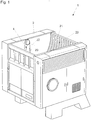
- FIG. 1 shows a crushing device 1, with a machine frame 2.
- the machine frame 2 a skeleton, a supporting device, via which the crushing device 1 is supported on the ground, walls and panels to the outside.
- Material to be comminuted is fed to the comminuting device 1 via a material feed space 20. Furthermore, a feed device 4 is pivotally mounted about an axis of rotation 22 on the side walls of the crushing device 1. This conveys the material to be crushed further to a crushing rotor 3 (in the FIG. 1 not to be seen).
- the feed device 4 comprises a slider 24 with a Nachdrück design 33.
- the slider 24 may be formed, for example, in cross-section substantially wedge-shaped.
- the slider 24 is connected via two spaced-apart lever 23 with a pivot point 34.
- a linearly adjustable feeding device can also be used.
- the slider 24 or the feeding device 4 moves along a wall portion 21, between a first end position 5 and a second end position 6, wherein the first end position 5 is adjacent to a crushing rotor 3 and the second end position 6 is spaced therefrom.
- the slider 24 and the feeding device 4 take any position between these two end positions 5 and 6.
- the thereby traversed positions are indicated by a dash-dotted line 35.
- the Movement directions of the slider 24 and the feeding device 4 are indicated by a double arrow 18.
- the feeding device 4 is driven by two hydraulic piston-cylinder devices 15, each comprising a cylinder 29 and a piston movable therein with a piston rod 30.
- the cylinder 29 is fixed to the machine frame 2.
- the piston rod 30 is pivotally connected via an intermediate lever 25 to the lever arm 23.
- a reverse configuration may be used in which the piston rod 30 is fixed to the machine frame 2 and the cylinder 29 acts on the intermediate lever 25.
- the piston-cylinder device 15 and the intermediate lever 25 are each arranged in a side wall of the crushing device 1.
- the intermediate lever 25 is rotatably connected to the lever arm 23.
- the material supplied by the feed device 4 to the comminution rotor 3 is comminuted by cutting devices arranged on the shell of the comminution rotor 3 and stationary counterblades 26, until the material has a certain degree of comminution, which can be adjusted via a screening device 27 is. About the screening device 27, the crushed material passes to the outside and can be removed for example via conveyor belts.
- the crushing rotor 3 is rotatably mounted about a pivot point 36 on the machine frame 2.
- the directions of rotation are identified by the reference numeral 17 and a double arrow.
- the presence of the feeder 4 in one of the two end positions 5 and 6 by two stationary sensors 28, which may be formed as inductive sensors, can be determined.
- the sensors 28 are connected via a signal transmission device 11 with a control and / or regulating device 10.
- the position of the at least one feed device 4 between these two end positions 5 and 6 can not be determined.
- the so associated disadvantages are described in detail above. It is not excluded that such sensors are also used in the present invention.
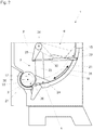
- FIG. 4 shows a first preferred embodiment of the crushing device 1 and the method for operating the crushing device 1.
- the hydraulic piston-cylinder device 15 is supplied with a hydraulic fluid via a supply line 12 and a discharge line 13.
- the hydraulic fluid can be stored in a tank 31 which is connected via a pump 37 and a proportional valve 32 to the supply line 12 and the discharge line 13 in connection.
- a measuring device 7 is now provided, which is set up to measure the volume flow of the hydraulic fluid in the supply line 12 and the discharge line 13.
- the measurement signals are forwarded via a signal transmission device 11 to the control and / or regulating device 10, in which the position of the feed device 4 between the two end positions 5 and 6 is continuously determined from the measurement signals provided.
- FIG. 5 shows a second preferred embodiment of the crushing device 1 and the method for operating the crushing device 1.
- a displacement measuring device 8 is used, which comprises a cable potentiometer in the illustrated case.
- the measurement signals are forwarded via a signal transmission device 11 to the control and / or regulating device 10, in which the position of the feed device 4 between the two end positions 5 and 6 is determined continuously from the measurement signals provided.
- FIG. 6 shows a third preferred embodiment of the crushing device 1 and the method for operating the crushing device 1.
- This is a measuring device 9 is used, which is adapted to measure a pivot angle 14 of the feeder 4, wherein the measuring device 9 comprises a rotary encoder.
- the measurement signals are transmitted via a signal transmission device 11 to the control and / or control device 10 forwarded, in which from the measurement signals provided continuously the position of the feeding device 4 between the two end positions 5 and 6 is determined.
- the thus determined position of the feed device 4 serves as a starting point for the advantageous embodiments of the method for operating the comminution device 1 described above.
- the control and / or regulating device 10 may be connected by signal technology to a display device 19 in order to provide information to a user of the comminuting device 1, for example about malfunctions which can not be automatically remedied.
- measuring devices 28, 7, 8 and 9 need not be done at the illustrated locations of the feeder 4. It can be used here any offering place.
- the measuring devices do not necessarily have to be coupled directly to the at least one feed device.
- an arrangement in a wall, on which the at least one feeding device moves along, is also possible.
Landscapes
- Engineering & Computer Science (AREA)
- Food Science & Technology (AREA)
- Crushing And Pulverization Processes (AREA)
Priority Applications (9)
| Application Number | Priority Date | Filing Date | Title |
|---|---|---|---|
| PT171875149T PT3446786T (pt) | 2017-08-23 | 2017-08-23 | Dispositivo de trituração para triturar material |
| ES17187514T ES2767682T3 (es) | 2017-08-23 | 2017-08-23 | Dispositivo de trituración para triturar material |
| PL17187514T PL3446786T3 (pl) | 2017-08-23 | 2017-08-23 | Urządzenie rozdrabniające do rozdrabniania materiału |
| EP17187514.9A EP3446786B1 (fr) | 2017-08-23 | 2017-08-23 | Dispositif de broyage permettant le broyage de matériau |
| DK17187514.9T DK3446786T3 (da) | 2017-08-23 | 2017-08-23 | Knusningsindretning til knusning af materiale |
| SI201730166T SI3446786T1 (sl) | 2017-08-23 | 2017-08-23 | Drobilna naprava za drobljenje materiala |
| CA3073630A CA3073630C (fr) | 2017-08-23 | 2018-08-20 | Dispositif de broyage pour broyer de la matiere |
| PCT/EP2018/072422 WO2019038227A1 (fr) | 2017-08-23 | 2018-08-20 | Dispositif de broyage pour broyer de la matière |
| US16/794,352 US11446676B2 (en) | 2017-08-23 | 2020-02-19 | Shredder device for shredding material |
Applications Claiming Priority (1)
| Application Number | Priority Date | Filing Date | Title |
|---|---|---|---|
| EP17187514.9A EP3446786B1 (fr) | 2017-08-23 | 2017-08-23 | Dispositif de broyage permettant le broyage de matériau |
Publications (2)
| Publication Number | Publication Date |
|---|---|
| EP3446786A1 true EP3446786A1 (fr) | 2019-02-27 |
| EP3446786B1 EP3446786B1 (fr) | 2019-10-16 |
Family
ID=59686869
Family Applications (1)
| Application Number | Title | Priority Date | Filing Date |
|---|---|---|---|
| EP17187514.9A Active EP3446786B1 (fr) | 2017-08-23 | 2017-08-23 | Dispositif de broyage permettant le broyage de matériau |
Country Status (9)
| Country | Link |
|---|---|
| US (1) | US11446676B2 (fr) |
| EP (1) | EP3446786B1 (fr) |
| CA (1) | CA3073630C (fr) |
| DK (1) | DK3446786T3 (fr) |
| ES (1) | ES2767682T3 (fr) |
| PL (1) | PL3446786T3 (fr) |
| PT (1) | PT3446786T (fr) |
| SI (1) | SI3446786T1 (fr) |
| WO (1) | WO2019038227A1 (fr) |
Cited By (3)
| Publication number | Priority date | Publication date | Assignee | Title |
|---|---|---|---|---|
| CN112387340A (zh) * | 2020-10-26 | 2021-02-23 | 龙南新涛亚克力科技有限公司 | 一种亚克力板废料全面粉碎机 |
| DE102020114510B3 (de) | 2020-05-29 | 2021-09-30 | Vecoplan Ag | Zerkleinerungsvorrichtung umfassend eine Vorschubeinrichtung mit einer elektromotorischen Antriebseinrichtung |
| CN113546717A (zh) * | 2021-07-18 | 2021-10-26 | 王新涛 | 一种混合建筑废料的预处理设备 |
Families Citing this family (1)
| Publication number | Priority date | Publication date | Assignee | Title |
|---|---|---|---|---|
| CN119633957B (zh) * | 2024-11-29 | 2025-10-10 | 安徽农业大学 | 一种农业种植肥料生产加工粉碎装置 |
Citations (3)
| Publication number | Priority date | Publication date | Assignee | Title |
|---|---|---|---|---|
| US4423844A (en) * | 1981-10-02 | 1984-01-03 | Triple/S Dynamics, Inc. | Apparatus for shredding materials |
| US6016979A (en) * | 1997-04-18 | 2000-01-25 | Integrated Recycling Systems Ltd. | System for processing big refuse such as a spring-containing mattress and the like |
| DE202012004224U1 (de) * | 2011-05-04 | 2012-05-16 | Atm Recyclingsystems Gmbh | Rotorschere |
Family Cites Families (23)
| Publication number | Priority date | Publication date | Assignee | Title |
|---|---|---|---|---|
| US4061280A (en) * | 1976-10-29 | 1977-12-06 | Box Theodor | Mixing apparatus for feed to injection molding machine |
| US4127236A (en) * | 1977-09-12 | 1978-11-28 | William Lasar | Meat flaking machine |
| US4394984A (en) * | 1981-01-05 | 1983-07-26 | Polar Bear, Inc. | Ice block loading mechanism for an ice shaving machine |
| US4655403A (en) * | 1982-11-08 | 1987-04-07 | Sciortino Ronald R | Ice shaving machine with stabilization means |
| DE4228058C2 (de) * | 1992-08-24 | 1995-04-20 | Kloeckner Humboldt Deutz Ag | Anlage und Verfahren zur Druckbehandlung körnigen Gutes |
| US5209413A (en) * | 1992-10-16 | 1993-05-11 | Paul Dwyer | Device for shredding cylindrical bales |
| US5379955A (en) * | 1993-09-24 | 1995-01-10 | The United States Of America As Represented By The Secretary Of The Navy | Infeed hopper with pivotable throat for shredder or granulator |
| US5695134A (en) * | 1996-04-10 | 1997-12-09 | Williams; Robert M. | Material reducing hammer mill with internal air circulating fan |
| US5988544A (en) * | 1998-10-08 | 1999-11-23 | Williams, Jr.; Robert M. | Rotary grinder cutting block |
| US6405949B1 (en) * | 1998-10-28 | 2002-06-18 | Stephen B. Maguire | Shuttle granulator |
| US20070029418A1 (en) * | 2005-07-26 | 2007-02-08 | Jakobi Felix F | Infectious waste treatment |
| ITMI20071165A1 (it) * | 2007-06-08 | 2008-12-09 | Satrind S P A | Trituratore per scarti comprendente almeno due rotori |
| IT1392590B1 (it) * | 2008-12-11 | 2012-03-09 | Colombo Giovanni SRL | Mulino trituratore e relativo procedimento di triturazione |
| EP2218508A1 (fr) * | 2009-02-17 | 2010-08-18 | Lindner-Recyclingtech GmbH | Dispositif de broyage |
| US7926753B2 (en) * | 2009-03-25 | 2011-04-19 | Martin Yale Industries, Inc. | Material and packaging shredding machine |
| EP2658707B1 (fr) * | 2010-11-12 | 2015-09-02 | SIB Strautmann Ingenieurbüro GmbH | Dispositif de transport et/ou de pressage avec un dispositif d'alimentation monté en amont |
| DE102011086693A1 (de) * | 2011-05-05 | 2012-11-08 | Herbold Meckesheim Gmbh | Vorrichtung zum Zerkleinern von Aufgabegut |
| EP2857101B1 (fr) * | 2013-10-01 | 2015-07-08 | Manuel Lindner | Dispositif de broyage doté d'un clapet de maintenance |
| EP2857103B1 (fr) * | 2013-10-04 | 2019-01-16 | Lindner, Manuel | Dispositif de broyage |
| DE102015003991A1 (de) * | 2015-03-30 | 2016-10-06 | Weima Maschinenbau Gmbh | Vorrichtung zum Zerkleinern von Material, insbesondere von medizinischem Abfallmaterial |
| LT3326728T (lt) * | 2015-07-17 | 2019-12-27 | Ibircom S.A. | Komunalinių kietų organinių ir neorganinių atliekų transformavimo į agregatus būdas ir aparatas |
| SI3238823T1 (en) * | 2016-04-29 | 2018-08-31 | Untha Shredding Technology Gmbh | Crushing machine |
| AR105718A1 (es) * | 2016-08-16 | 2017-11-01 | Aner Andres Adalberto | Método natural de reducción y/o liberación de agentes patógenos y microorganismos contenidos en sólidos |
-
2017
- 2017-08-23 ES ES17187514T patent/ES2767682T3/es active Active
- 2017-08-23 SI SI201730166T patent/SI3446786T1/sl unknown
- 2017-08-23 PT PT171875149T patent/PT3446786T/pt unknown
- 2017-08-23 PL PL17187514T patent/PL3446786T3/pl unknown
- 2017-08-23 EP EP17187514.9A patent/EP3446786B1/fr active Active
- 2017-08-23 DK DK17187514.9T patent/DK3446786T3/da active
-
2018
- 2018-08-20 CA CA3073630A patent/CA3073630C/fr active Active
- 2018-08-20 WO PCT/EP2018/072422 patent/WO2019038227A1/fr not_active Ceased
-
2020
- 2020-02-19 US US16/794,352 patent/US11446676B2/en active Active
Patent Citations (3)
| Publication number | Priority date | Publication date | Assignee | Title |
|---|---|---|---|---|
| US4423844A (en) * | 1981-10-02 | 1984-01-03 | Triple/S Dynamics, Inc. | Apparatus for shredding materials |
| US6016979A (en) * | 1997-04-18 | 2000-01-25 | Integrated Recycling Systems Ltd. | System for processing big refuse such as a spring-containing mattress and the like |
| DE202012004224U1 (de) * | 2011-05-04 | 2012-05-16 | Atm Recyclingsystems Gmbh | Rotorschere |
Cited By (5)
| Publication number | Priority date | Publication date | Assignee | Title |
|---|---|---|---|---|
| DE102020114510B3 (de) | 2020-05-29 | 2021-09-30 | Vecoplan Ag | Zerkleinerungsvorrichtung umfassend eine Vorschubeinrichtung mit einer elektromotorischen Antriebseinrichtung |
| EP3919178A1 (fr) | 2020-05-29 | 2021-12-08 | Vecoplan AG | Dispositif de broyage comprenant un dispositif d'avance doté d'un dispositif d'entrainement électromoteur |
| US11986832B2 (en) | 2020-05-29 | 2024-05-21 | Vecoplan Ag | Comminuting apparatus comprising a feed device with an electromotive drive device |
| CN112387340A (zh) * | 2020-10-26 | 2021-02-23 | 龙南新涛亚克力科技有限公司 | 一种亚克力板废料全面粉碎机 |
| CN113546717A (zh) * | 2021-07-18 | 2021-10-26 | 王新涛 | 一种混合建筑废料的预处理设备 |
Also Published As
| Publication number | Publication date |
|---|---|
| EP3446786B1 (fr) | 2019-10-16 |
| CA3073630C (fr) | 2022-07-12 |
| PL3446786T3 (pl) | 2020-05-18 |
| CA3073630A1 (fr) | 2019-02-28 |
| DK3446786T3 (da) | 2020-01-27 |
| US20200179938A1 (en) | 2020-06-11 |
| ES2767682T3 (es) | 2020-06-18 |
| US11446676B2 (en) | 2022-09-20 |
| WO2019038227A1 (fr) | 2019-02-28 |
| SI3446786T1 (sl) | 2020-03-31 |
| PT3446786T (pt) | 2020-01-22 |
Similar Documents
| Publication | Publication Date | Title |
|---|---|---|
| EP3446786B1 (fr) | Dispositif de broyage permettant le broyage de matériau | |
| EP0371519B1 (fr) | Presse à granuler | |
| DE3838314A1 (de) | Falzklappenzylinder fuer eine rollenrotationsdruckmaschine | |
| DE2655655C2 (de) | Brecher | |
| DE19632977B4 (de) | Vorrichtung und Verfahren zur Einzugssteuerung eines Feldhäckslers | |
| DE102013201633B3 (de) | Einrichtung zur Verstellung der Position einer Gegenschneide gegenüber einer Häckseleinrichtung | |
| DE102006036136A1 (de) | Zerkleinerungsvorrichtung für Flachmaterial und Verfahren zum Betrieb einer solchen Zerkleinerungsvorrichtung | |
| EP2436259A1 (fr) | Dispositif de préparation doté d'un dispositif de commande électronique pour une machine de travail agricole | |
| DE102016208230A1 (de) | Produktverteilungsvorrichtung | |
| EP2637792B1 (fr) | Système d'entraînement pour un broyeur à boulets et procédé de fonctionnement d'un broyeur à boulets | |
| CH635266A5 (de) | Druck-steuereinrichtung fuer eine hydraulisch angetriebene stossmaschine, insbesondere eine zahnradstossmaschine. | |
| EP3199041B1 (fr) | Unité de bande aspirante comprenant un dispositif de réglage servant à régler la distance entre un disque de pression de l'unité de bande aspirante et un élément racloir et procédé associé | |
| DE69903997T2 (de) | Verteilungsmaschine für Viehfutter und ähnliches | |
| DE102012223432B3 (de) | Anordnung zur Verstellung eines Auswurfbeschleunigerspalts zwischen dem von Paddeln eines Rotors einer Auswurfbeschleunigungseinrichtung eines Feldhäckslers beschriebenen Hüllkreis und einem konkaven Bereich eines den Rotor aufnehmenden Gehäuses | |
| DE102012102525B4 (de) | Pressenantrieb mit mehreren Betriebsmodi für eine Presse und Verfahren zum Betreiben eines Pressenantriebs | |
| EP1385768B1 (fr) | Procede d'ajustage d'un galet de guidage | |
| EP1471020B1 (fr) | Barre de retournement | |
| DE2940375C2 (de) | Verfahren und Einrichtung zur automatischen Ausscheidung der vorderen und hinteren Enden von Materialstangen | |
| DE1411773A1 (de) | Vorrichtung an einem Falzwerk zur Herstellung von parallel zur Papierlaufrichtung gefalzten Druckexemplaren | |
| DE3914860A1 (de) | Hydraulische antriebsvorrichtung | |
| DE112007000152B4 (de) | Verfahren zum Regeln des Antriebs einer Vortriebs- oder Gewinnungsmaschine | |
| DE202012004224U1 (de) | Rotorschere | |
| DE202012012581U1 (de) | Automatische Fertigungsmaschine mit elektrischer Antriebssteuerung | |
| DE1159803B (de) | Zerkleinerungsmaschine fuer Fleisch, Brot u. dgl. | |
| DE2166515A1 (de) | Elektromotorische antriebsanordnung |
Legal Events
| Date | Code | Title | Description |
|---|---|---|---|
| STAA | Information on the status of an ep patent application or granted ep patent |
Free format text: STATUS: EXAMINATION IS IN PROGRESS |
|
| PUAI | Public reference made under article 153(3) epc to a published international application that has entered the european phase |
Free format text: ORIGINAL CODE: 0009012 |
|
| 17P | Request for examination filed |
Effective date: 20180920 |
|
| AK | Designated contracting states |
Kind code of ref document: A1 Designated state(s): AL AT BE BG CH CY CZ DE DK EE ES FI FR GB GR HR HU IE IS IT LI LT LU LV MC MK MT NL NO PL PT RO RS SE SI SK SM TR |
|
| AX | Request for extension of the european patent |
Extension state: BA ME |
|
| GRAP | Despatch of communication of intention to grant a patent |
Free format text: ORIGINAL CODE: EPIDOSNIGR1 |
|
| STAA | Information on the status of an ep patent application or granted ep patent |
Free format text: STATUS: GRANT OF PATENT IS INTENDED |
|
| INTG | Intention to grant announced |
Effective date: 20190322 |
|
| GRAS | Grant fee paid |
Free format text: ORIGINAL CODE: EPIDOSNIGR3 |
|
| GRAA | (expected) grant |
Free format text: ORIGINAL CODE: 0009210 |
|
| STAA | Information on the status of an ep patent application or granted ep patent |
Free format text: STATUS: THE PATENT HAS BEEN GRANTED |
|
| AK | Designated contracting states |
Kind code of ref document: B1 Designated state(s): AL AT BE BG CH CY CZ DE DK EE ES FI FR GB GR HR HU IE IS IT LI LT LU LV MC MK MT NL NO PL PT RO RS SE SI SK SM TR |
|
| REG | Reference to a national code |
Ref country code: GB Ref legal event code: FG4D Free format text: NOT ENGLISH |
|
| REG | Reference to a national code |
Ref country code: DE Ref legal event code: R096 Ref document number: 502017002580 Country of ref document: DE Ref country code: CH Ref legal event code: EP |
|
| REG | Reference to a national code |
Ref country code: IE Ref legal event code: FG4D Free format text: LANGUAGE OF EP DOCUMENT: GERMAN |
|
| REG | Reference to a national code |
Ref country code: AT Ref legal event code: REF Ref document number: 1190773 Country of ref document: AT Kind code of ref document: T Effective date: 20191115 |
|
| REG | Reference to a national code |
Ref country code: FI Ref legal event code: FGE |
|
| REG | Reference to a national code |
Ref country code: PT Ref legal event code: SC4A Ref document number: 3446786 Country of ref document: PT Date of ref document: 20200122 Kind code of ref document: T Free format text: AVAILABILITY OF NATIONAL TRANSLATION Effective date: 20200114 |
|
| REG | Reference to a national code |
Ref country code: DK Ref legal event code: T3 Effective date: 20200123 |
|
| REG | Reference to a national code |
Ref country code: CH Ref legal event code: NV Representative=s name: WEINMANN ZIMMERLI, CH |
|
| REG | Reference to a national code |
Ref country code: SE Ref legal event code: TRGR |
|
| REG | Reference to a national code |
Ref country code: NL Ref legal event code: FP |
|
| REG | Reference to a national code |
Ref country code: NO Ref legal event code: T2 Effective date: 20191016 |
|
| REG | Reference to a national code |
Ref country code: LT Ref legal event code: MG4D |
|
| REG | Reference to a national code |
Ref country code: SK Ref legal event code: T3 Ref document number: E 33232 Country of ref document: SK |
|
| PG25 | Lapsed in a contracting state [announced via postgrant information from national office to epo] |
Ref country code: BG Free format text: LAPSE BECAUSE OF FAILURE TO SUBMIT A TRANSLATION OF THE DESCRIPTION OR TO PAY THE FEE WITHIN THE PRESCRIBED TIME-LIMIT Effective date: 20200116 Ref country code: GR Free format text: LAPSE BECAUSE OF FAILURE TO SUBMIT A TRANSLATION OF THE DESCRIPTION OR TO PAY THE FEE WITHIN THE PRESCRIBED TIME-LIMIT Effective date: 20200117 Ref country code: LV Free format text: LAPSE BECAUSE OF FAILURE TO SUBMIT A TRANSLATION OF THE DESCRIPTION OR TO PAY THE FEE WITHIN THE PRESCRIBED TIME-LIMIT Effective date: 20191016 Ref country code: LT Free format text: LAPSE BECAUSE OF FAILURE TO SUBMIT A TRANSLATION OF THE DESCRIPTION OR TO PAY THE FEE WITHIN THE PRESCRIBED TIME-LIMIT Effective date: 20191016 |
|
| PG25 | Lapsed in a contracting state [announced via postgrant information from national office to epo] |
Ref country code: HR Free format text: LAPSE BECAUSE OF FAILURE TO SUBMIT A TRANSLATION OF THE DESCRIPTION OR TO PAY THE FEE WITHIN THE PRESCRIBED TIME-LIMIT Effective date: 20191016 Ref country code: RS Free format text: LAPSE BECAUSE OF FAILURE TO SUBMIT A TRANSLATION OF THE DESCRIPTION OR TO PAY THE FEE WITHIN THE PRESCRIBED TIME-LIMIT Effective date: 20191016 Ref country code: IS Free format text: LAPSE BECAUSE OF FAILURE TO SUBMIT A TRANSLATION OF THE DESCRIPTION OR TO PAY THE FEE WITHIN THE PRESCRIBED TIME-LIMIT Effective date: 20200224 |
|
| REG | Reference to a national code |
Ref country code: ES Ref legal event code: FG2A Ref document number: 2767682 Country of ref document: ES Kind code of ref document: T3 Effective date: 20200618 |
|
| PG25 | Lapsed in a contracting state [announced via postgrant information from national office to epo] |
Ref country code: AL Free format text: LAPSE BECAUSE OF FAILURE TO SUBMIT A TRANSLATION OF THE DESCRIPTION OR TO PAY THE FEE WITHIN THE PRESCRIBED TIME-LIMIT Effective date: 20191016 |
|
| REG | Reference to a national code |
Ref country code: DE Ref legal event code: R097 Ref document number: 502017002580 Country of ref document: DE |
|
| PG2D | Information on lapse in contracting state deleted |
Ref country code: IS |
|
| PG25 | Lapsed in a contracting state [announced via postgrant information from national office to epo] |
Ref country code: RO Free format text: LAPSE BECAUSE OF FAILURE TO SUBMIT A TRANSLATION OF THE DESCRIPTION OR TO PAY THE FEE WITHIN THE PRESCRIBED TIME-LIMIT Effective date: 20191016 Ref country code: EE Free format text: LAPSE BECAUSE OF FAILURE TO SUBMIT A TRANSLATION OF THE DESCRIPTION OR TO PAY THE FEE WITHIN THE PRESCRIBED TIME-LIMIT Effective date: 20191016 Ref country code: IS Free format text: LAPSE BECAUSE OF FAILURE TO SUBMIT A TRANSLATION OF THE DESCRIPTION OR TO PAY THE FEE WITHIN THE PRESCRIBED TIME-LIMIT Effective date: 20200216 |
|
| PLBE | No opposition filed within time limit |
Free format text: ORIGINAL CODE: 0009261 |
|
| STAA | Information on the status of an ep patent application or granted ep patent |
Free format text: STATUS: NO OPPOSITION FILED WITHIN TIME LIMIT |
|
| PG25 | Lapsed in a contracting state [announced via postgrant information from national office to epo] |
Ref country code: SM Free format text: LAPSE BECAUSE OF FAILURE TO SUBMIT A TRANSLATION OF THE DESCRIPTION OR TO PAY THE FEE WITHIN THE PRESCRIBED TIME-LIMIT Effective date: 20191016 |
|
| 26N | No opposition filed |
Effective date: 20200717 |
|
| PG25 | Lapsed in a contracting state [announced via postgrant information from national office to epo] |
Ref country code: MC Free format text: LAPSE BECAUSE OF FAILURE TO SUBMIT A TRANSLATION OF THE DESCRIPTION OR TO PAY THE FEE WITHIN THE PRESCRIBED TIME-LIMIT Effective date: 20191016 |
|
| PG25 | Lapsed in a contracting state [announced via postgrant information from national office to epo] |
Ref country code: LU Free format text: LAPSE BECAUSE OF NON-PAYMENT OF DUE FEES Effective date: 20200823 |
|
| PG25 | Lapsed in a contracting state [announced via postgrant information from national office to epo] |
Ref country code: TR Free format text: LAPSE BECAUSE OF FAILURE TO SUBMIT A TRANSLATION OF THE DESCRIPTION OR TO PAY THE FEE WITHIN THE PRESCRIBED TIME-LIMIT Effective date: 20191016 Ref country code: MT Free format text: LAPSE BECAUSE OF FAILURE TO SUBMIT A TRANSLATION OF THE DESCRIPTION OR TO PAY THE FEE WITHIN THE PRESCRIBED TIME-LIMIT Effective date: 20191016 Ref country code: CY Free format text: LAPSE BECAUSE OF FAILURE TO SUBMIT A TRANSLATION OF THE DESCRIPTION OR TO PAY THE FEE WITHIN THE PRESCRIBED TIME-LIMIT Effective date: 20191016 |
|
| PG25 | Lapsed in a contracting state [announced via postgrant information from national office to epo] |
Ref country code: MK Free format text: LAPSE BECAUSE OF FAILURE TO SUBMIT A TRANSLATION OF THE DESCRIPTION OR TO PAY THE FEE WITHIN THE PRESCRIBED TIME-LIMIT Effective date: 20191016 |
|
| PGFP | Annual fee paid to national office [announced via postgrant information from national office to epo] |
Ref country code: NL Payment date: 20250723 Year of fee payment: 9 |
|
| PGFP | Annual fee paid to national office [announced via postgrant information from national office to epo] |
Ref country code: ES Payment date: 20250901 Year of fee payment: 9 Ref country code: PT Payment date: 20250725 Year of fee payment: 9 Ref country code: FI Payment date: 20250724 Year of fee payment: 9 |
|
| PGFP | Annual fee paid to national office [announced via postgrant information from national office to epo] |
Ref country code: DK Payment date: 20250825 Year of fee payment: 9 |
|
| PGFP | Annual fee paid to national office [announced via postgrant information from national office to epo] |
Ref country code: NO Payment date: 20250729 Year of fee payment: 9 |
|
| PGFP | Annual fee paid to national office [announced via postgrant information from national office to epo] |
Ref country code: PL Payment date: 20250708 Year of fee payment: 9 Ref country code: IT Payment date: 20250806 Year of fee payment: 9 |
|
| PGFP | Annual fee paid to national office [announced via postgrant information from national office to epo] |
Ref country code: BE Payment date: 20250723 Year of fee payment: 9 Ref country code: GB Payment date: 20250821 Year of fee payment: 9 |
|
| PGFP | Annual fee paid to national office [announced via postgrant information from national office to epo] |
Ref country code: FR Payment date: 20250724 Year of fee payment: 9 Ref country code: AT Payment date: 20250827 Year of fee payment: 9 |
|
| PGFP | Annual fee paid to national office [announced via postgrant information from national office to epo] |
Ref country code: CH Payment date: 20250901 Year of fee payment: 9 Ref country code: SE Payment date: 20250731 Year of fee payment: 9 |
|
| PGFP | Annual fee paid to national office [announced via postgrant information from national office to epo] |
Ref country code: IE Payment date: 20250724 Year of fee payment: 9 Ref country code: CZ Payment date: 20250709 Year of fee payment: 9 |
|
| PGFP | Annual fee paid to national office [announced via postgrant information from national office to epo] |
Ref country code: SK Payment date: 20250711 Year of fee payment: 9 |
|
| PGFP | Annual fee paid to national office [announced via postgrant information from national office to epo] |
Ref country code: SI Payment date: 20250724 Year of fee payment: 9 |
|
| PGFP | Annual fee paid to national office [announced via postgrant information from national office to epo] |
Ref country code: DE Payment date: 20251027 Year of fee payment: 9 |