EP3449641B1 - Détection de défaillance de système de casque d'écoute - Google Patents
Détection de défaillance de système de casque d'écoute Download PDFInfo
- Publication number
- EP3449641B1 EP3449641B1 EP16900692.1A EP16900692A EP3449641B1 EP 3449641 B1 EP3449641 B1 EP 3449641B1 EP 16900692 A EP16900692 A EP 16900692A EP 3449641 B1 EP3449641 B1 EP 3449641B1
- Authority
- EP
- European Patent Office
- Prior art keywords
- wire
- electrical signal
- signal
- failure
- failure detection
- Prior art date
- Legal status (The legal status is an assumption and is not a legal conclusion. Google has not performed a legal analysis and makes no representation as to the accuracy of the status listed.)
- Active
Links
Images


Classifications
-
- H—ELECTRICITY
- H04—ELECTRIC COMMUNICATION TECHNIQUE
- H04R—LOUDSPEAKERS, MICROPHONES, GRAMOPHONE PICK-UPS OR LIKE ACOUSTIC ELECTROMECHANICAL TRANSDUCERS; ELECTRIC HEARING AIDS; PUBLIC ADDRESS SYSTEMS
- H04R29/00—Monitoring arrangements; Testing arrangements
- H04R29/001—Monitoring arrangements; Testing arrangements for loudspeakers
-
- G—PHYSICS
- G10—MUSICAL INSTRUMENTS; ACOUSTICS
- G10K—SOUND-PRODUCING DEVICES; METHODS OR DEVICES FOR PROTECTING AGAINST, OR FOR DAMPING, NOISE OR OTHER ACOUSTIC WAVES IN GENERAL; ACOUSTICS NOT OTHERWISE PROVIDED FOR
- G10K11/00—Methods or devices for transmitting, conducting or directing sound in general; Methods or devices for protecting against, or for damping, noise or other acoustic waves in general
- G10K11/16—Methods or devices for protecting against, or for damping, noise or other acoustic waves in general
- G10K11/175—Methods or devices for protecting against, or for damping, noise or other acoustic waves in general using interference effects; Masking sound
- G10K11/178—Methods or devices for protecting against, or for damping, noise or other acoustic waves in general using interference effects; Masking sound by electro-acoustically regenerating the original acoustic waves in anti-phase
- G10K11/1783—Methods or devices for protecting against, or for damping, noise or other acoustic waves in general using interference effects; Masking sound by electro-acoustically regenerating the original acoustic waves in anti-phase handling or detecting of non-standard events or conditions, e.g. changing operating modes under specific operating conditions
- G10K11/17833—Methods or devices for protecting against, or for damping, noise or other acoustic waves in general using interference effects; Masking sound by electro-acoustically regenerating the original acoustic waves in anti-phase handling or detecting of non-standard events or conditions, e.g. changing operating modes under specific operating conditions by using a self-diagnostic function or a malfunction prevention function, e.g. detecting abnormal output levels
-
- G—PHYSICS
- G10—MUSICAL INSTRUMENTS; ACOUSTICS
- G10L—SPEECH ANALYSIS TECHNIQUES OR SPEECH SYNTHESIS; SPEECH RECOGNITION; SPEECH OR VOICE PROCESSING TECHNIQUES; SPEECH OR AUDIO CODING OR DECODING
- G10L21/00—Speech or voice signal processing techniques to produce another audible or non-audible signal, e.g. visual or tactile, in order to modify its quality or its intelligibility
- G10L21/02—Speech enhancement, e.g. noise reduction or echo cancellation
- G10L21/0208—Noise filtering
- G10L21/0216—Noise filtering characterised by the method used for estimating noise
-
- H—ELECTRICITY
- H04—ELECTRIC COMMUNICATION TECHNIQUE
- H04R—LOUDSPEAKERS, MICROPHONES, GRAMOPHONE PICK-UPS OR LIKE ACOUSTIC ELECTROMECHANICAL TRANSDUCERS; ELECTRIC HEARING AIDS; PUBLIC ADDRESS SYSTEMS
- H04R1/00—Details of transducers, loudspeakers or microphones
- H04R1/10—Earpieces; Attachments therefor ; Earphones; Monophonic headphones
- H04R1/1083—Reduction of ambient noise
-
- G—PHYSICS
- G10—MUSICAL INSTRUMENTS; ACOUSTICS
- G10K—SOUND-PRODUCING DEVICES; METHODS OR DEVICES FOR PROTECTING AGAINST, OR FOR DAMPING, NOISE OR OTHER ACOUSTIC WAVES IN GENERAL; ACOUSTICS NOT OTHERWISE PROVIDED FOR
- G10K2210/00—Details of active noise control [ANC] covered by G10K11/178 but not provided for in any of its subgroups
- G10K2210/10—Applications
- G10K2210/108—Communication systems, e.g. where useful sound is kept and noise is cancelled
- G10K2210/1081—Earphones, e.g. for telephones, ear protectors or headsets
-
- G—PHYSICS
- G10—MUSICAL INSTRUMENTS; ACOUSTICS
- G10K—SOUND-PRODUCING DEVICES; METHODS OR DEVICES FOR PROTECTING AGAINST, OR FOR DAMPING, NOISE OR OTHER ACOUSTIC WAVES IN GENERAL; ACOUSTICS NOT OTHERWISE PROVIDED FOR
- G10K2210/00—Details of active noise control [ANC] covered by G10K11/178 but not provided for in any of its subgroups
- G10K2210/50—Miscellaneous
- G10K2210/503—Diagnostics; Stability; Alarms; Failsafe
Definitions
- a sound wave is a pressure wave comprising alternating periods of compression and rarefaction.
- Active noise reduction which may be referred to as noise cancellation or control (ANC) uses two sound waves.
- a first sound wave is an undesired sound wave, which may be referred to as noise.
- a second sound wave has the same amplitude as the first wave, but with a phase that is inverted compared to the phase of the first wave. The first sound wave and the second sound wave combine and undergo destructive interference, effectively cancelling each other out.
- ANR is particularly important in high-noise environments such as construction, manufacturing, aircraft, and military combat areas. Those areas may experience loud sounds, which can damage the human ear and disrupt communication among people. It is therefore desirable to provide ANR that allows for safety and reliable communication.
- US 2012/328116 A1 discloses a headset to be connected to a mobile device, the headset comprising: a microphone bias line; a microphone circuit coupled to the bias line; and a failure detection circuit to detect a failure of the microphone circuit, the failure detection circuit to measure one of a microphone bias signal and a temperature of the headset, and then signal that a failure notification be transmitted to a remote supply management system using a network interface.
- EP 2 793 224 A1 discloses an active noise reduction (ANR) circuit comprising: a digital feed-forward ANR pathway coupled to a feed-forward microphone, to detect environmental sounds in an environment external to a casing, and coupled to a first acoustic driver to output sounds within the casing; and a user input; wherein the digital feed-forward ANR pathway applies a filter using a first set of coefficients to convert signals from the feed-forward microphone to feed-forward anti-noise sounds to reduce environmental sounds within the casing, and in response to activation of the user input, the digital feed-forward ANR pathway applies the filter using a second set of coefficients, the second set of coefficients reducing the degree of feed-forward ANR to enable human speech sounds in the environment external to the casing to be conveyed from the feed-forward microphone to the acoustic driver with less reduction than provided by the first set of coefficients.
- ANR active noise reduction
- a headset system detects failures in power supply wires, outer microphone wires, inner microphone wires, and speaker wires by distinguishing between spurious signals and aural-origin (AO) signals.
- the system uses available signals that are processed during normal operation. In other words, the system need not introduce signals in order to detect failures.
- the system may disable features such as ANR for safety and other purposes.
- FIG. 1 is a schematic diagram of a headset system 100.
- the system 100 generally comprises a headset 115, a control unit 120, and a wire system 170.
- the system 100 connects to a radio.
- the radio may instead be a Moving Picture Experts Group (MPEG)-1 or MPEG 2 Audio Layer III (MP3) player or another audio source that provides external sound.
- MPEG Moving Picture Experts Group
- MP3 MPEG 2 Audio Layer III
- the headset 115 comprises eartips 105 and earpieces 110.
- the eartips 105 allow the headset 115 to secure into a user's ear.
- the eartips 105 comprise foam, which provides high attenuation for sufficient hearing protection.
- the eartips 105 also comprise two sound ports, which transfer sound between transducers in the earpieces 110 and the ear canals.
- a fit test of the system 100 alerts the user if the eartips 105 are not properly inserted in the user's ear canals.
- the headset 115 and specifically the earpieces 110 are described further below with respect to FIG.2
- the control unit 120 comprises a battery compartment 125, indicator lights 130, a charger connector 135, a push-to-talk (PTT) button 140, a menu button 145, a confirm and on/off button 150, and a volume button 155.
- the battery compartment 125 provides a housing for a battery and comprises a ventilation filter to keep the battery cool.
- the indicator lights 130 support a user interface.
- the indicator lights 130 light up in different situations as follows: Color: Indication: green low noise dose yellow medium noise dose red high noise doses green high battery life yellow medium battery life red low battery life green pulsing user action succeeded yellow pulsing action is running red pulsing warning (with explanatory voice message) green, yellow, and red flash system is shutting down
- a noise dose refers to a measure of a sound amplitude and may be in units of decibels (dB) or A-weighted decibels (dBA).
- dose exposure refers to a noise dose on the inside of the earpiece 110.
- the control unit 120 measures dose exposure for protection of the user.
- the charger connector 135 provides a port to plug in a charging cable, which charges the battery.
- the PTT button 140 provides a radio functionality so that the user can press and hold the PTT button 140 to transmit data and can release the PTT button 140 to receive data.
- the menu button 145 initiates a menu upon being pressed, voice feedback presents menu options, and the menu button 145 cycles to subsequent menu options upon being pressed again.
- the confirm and on/off button 150 turns on the system 100 upon being pushed and held in place for two seconds and turns off the system 100 upon being pushed and held for three seconds. Upon being pushed, the confirm and on/off button 150 also selects a menu option and initiates a sub-menu if available.
- the volume button 155 provides plus and minus buttons, which respectively increase and decrease voice feedback volume, ambient sound volume, and radio volume.
- the wire system 170 comprises a headset connector 160, a radio connector 165, a clip 175, a boom microphone connector 180, wires 185, and a slider 190.
- the headset connector 160 connects the headset 115 to the control unit 120 via the wire system 170.
- the radio connector 165 connects the radio to the control unit 120 via the wire system 170.
- the clip 175 removes tension from the wire system 170 and secures the system 100 to a shirt or another article of clothing.
- the boom microphone connector provides a connection for an option boom microphone, which may improve outgoing communication quality using additional ANR.
- the wires 185 comprise an outer microphone wire, an inner microphone wire, a speaker wire, and a power supply wire for both a left ear side and a right ear side.
- the wires 185 communicate signals between the headset 115 and the control unit 120.
- the slider 190 moves up and down the wire system 170 to loosen or tighten the wire system 170 above and below the slider 190.
- FIG. 2 is a schematic diagram 200 of the headset 115 in FIG. 1 fitted in and on a right ear 250.
- the headset 115 has the same components for a left ear.
- FIG.2 shows that the right ear 250 comprises a pinna 260, an ear drum 270, and an ear canal 280.
- FIG. 2 shows that the earpiece 110 comprises an outer microphone 210, a speaker 220, an inner microphone 230, and seals 240 and that the earpiece 110 is fitted within the ear canal 280 and directed to the ear drum 270.
- the outer microphone 210 receives environmental sound from an outside environment, which may also be referred to as ambient sound.
- the outer microphone 210 couples to the control unit 120 via the outer microphone wire.
- the speaker 220 transmits to the user's ear canals an optimal mix of environmental sound and sound from the radio.
- the speaker 220 couples to the control unit 120 via the speaker wire.
- the inner microphone 230 performs voice pick-up, which is receiving spoken sound from a human voice present in front of an ear drum, thus enabling radio communication without an external microphone.
- the inner microphone 230 couples to the control unit 120 via the inner microphone wire.
- the seals 240 seal off the ear canal 280 from ambient noise.
- the power supply wire provides power to the headset 115 via a power supply in the control unit 120. The power supply is described further below with respect to FIG.3 .
- FIG. 3 is a schematic diagram of the control unit 120 in FIG. 1 according to an embodiment of the present invention.
- the control unit 120 comprises a processor 305; a memory 315; a voltage source 320; digital-to-analog converters (DACs) 325, 355; and analog-to-digital converters (ADCs) 330, 335, 345, 350.
- the control unit 120 is shown in a simplified manner, but may be designed in any manner suitable for implementing the disclosed embodiments.
- the processor 305 may be a microprocessor, logic unit, or central processing unit (CPU).
- the processor processes data from the memory 315; the DACs 325, 355; and the ADCs 330, 335, 345, 350.
- the processor 305 is implemented by any suitable combination of hardware, middleware, firmware, and software.
- the processor 305 may be implemented as one or more CPU chips, cores (e.g., as a multi-core processor), field-programmable gate arrays (FPGAs), application specific integrated circuits (ASICs), and digital signal processors (DSPs).
- the processor 305 comprises a failure detection component 310.
- the failure detection component 310 implements the disclosed embodiments described above.
- failure detection component 310 therefore provides a substantial improvement to the functionality of the control unit 120 and effects a transformation of the control unit 120 to a different state.
- the failure detection component 310 is implemented as instructions stored in the memory 315 and executed by the processor 305.
- the memory 315 comprises one or more disks, tape drives, and solid-state drives and may be used as an over-flow data storage device, to store programs when such programs are selected for execution, and to store instructions and data that are read during program execution.
- the memory 315 may be volatile and non-volatile and may be read-only memory (ROM), random-access memory (RAM), ternary content-addressable memory (TCAM), and static random-access memory (SRAM).
- the voltage source 320 provides a voltage to power the headset 115 and its components via the power supply wires.
- the DACs 325, 355 receive digital signals from the processor 305, convert the digital signals into analog signals, and provide the analog signals to the speakers via the speaker wires.
- the ADCs 330, 350 receive analog signals from the inner microphones 230 via the inner microphone wires, convert the analog signals into digital signals, and provide the digital signals to the processor 305.
- the ADCs 335, 345 receive analog signals from the outer microphones 210 via the outer microphone wires, convert the analog signals into digital signals, and provide the digital signals to the processor 305.
- the ADC 340 receives analog signals from the radio via a radio wire, converts the analog signals into digital signals, and provides the digital signals to the processor 305.
- the outer microphone 210 captures environmental sound
- the control unit 120 analyzes the environmental sound
- the speaker 220 reproduces the environmental sound at a safe level.
- the inner microphone 230 captures a noise signal
- the control unit 120 produces an appropriate inverted signal to destructively interfere with the noise signal
- the speaker 220 emits the inverted signal.
- the inverted signal therefore reduces the noise level.
- the control unit 120 also performs a fit test to ensure that the eartips 105 are properly inserted and that a minimum level of attenuation is achieved. If that minimum level of attenuation is not achieved, then the control unit 120 generates voice feedback, which the speaker 220 emits.
- a spurious signal which may also be referred to as a failure signal or a transient signal, is an electrical wave whose origin is an undesired electrical event.
- a spurious signal is typically short and does not occur due to normal functioning of a device such as the system 100. Rather, a spurious signal occurs as a result of a failure and generates at the point of the failure. In this context, the point of the failure is in the system 100.
- the origin of a spurious signal is not an aural event.
- a spurious signal is a type of non-aural (NA) signal.
- an AO signal is a sound wave whose origin is an aural event. For instance, an AO signal results from a person speaking or a door closing. An AO signal is immediately audible to a person.
- a device such as the outer microphones 210 and the inner microphones 230 then converts the AO signal from a sound wave to an electrical wave or electrical signal.
- the outer microphones 210, the speakers 220, and the inner microphones 230 need to cooperate correctly.
- the wires 185 including the outer microphone wires, inner microphone wires, speaker wires, power supply wires, may fail over time due to pressure, flexion, and general degradation.
- a failure of the wires 185 may cause the outer microphones 210 and the inner microphones 230 to fail.
- Such a failure may generate a spurious signal in the outer microphone wires, the inner microphone wires, or both.
- the spurious signal may cause a further failure of the ANR, communication, and dose exposure monitoring.
- the system 100 may generate sounds that are dangerous to human hearing.
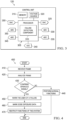
- FIG. 4 is a flowchart illustrating a method 400 of signal analysis and failure response according to an embodiment of the present invention.
- the system 100 and the processor 305, specifically the failure detection component 310 implement the method 400.
- the failure detection component 310 receives a frame.
- the frame represents a period of data corresponding to a signal or signals.
- step 410 describes a single frame, the method 400 applies to any number of frames.
- the failure detection component 310 receives the frame from at least one of the outer microphone wires or the inner microphone wires.
- One frame may comprise no signals representing sound while a subsequent frame may comprise such signals. In other words, some frames may correlate to periods of quiet.
- Each frame comprises a number of samples indicating data points at a specific time.
- the failure detection component 310 analyzes the frame. That analysis is described further below.
- the failure detection component 310 determines whether the frame comprises a spurious signal.
- the failure detection component 310 causes the system 100 to perform its normal functions. If the result of decision diamond 430 is yes, then the method 400 proceeds to step 450.
- the failure detection component 310 wants the user of a failure. The user may then choose to turn off the system 100 or restrict or disable some functions of the system 100 such as ANR.
- the failure detection component 310 marks dose exposure data. Specifically, the failure detection component 310 marks dose exposure data associated with the spurious signal in order to subsequently distinguish the dose exposure from the spurious signal and the dose exposure from desired AO signals.
- the failure detection component 310 restricts or disables functions of the system 100. For instance, the failure detection component 310 restricts or disables ANR because ANR may require that the system 100 be failure-less in order for the ANR to function properly.
- the failure detection component 310 may also restrict or disable the voice pick-up function or another function, or the failure detection component 310 may disable individual components such as the outer microphone 210, the speaker 220, or the inner microphone 230 for either ear or for both ears. If the failure detection component 310 restricts or disables components for one ear, then the failure detection component 310 may direct functionality to the corresponding components in the other ear. Alternatively, the failure detection component 310 turns off the system 100. Though the method 400 is shown as analyzing and responding to a single frame, the system 100, the processor 305, and the failure detection component 310 may perform the method 400 for any number of frames.
- the outer microphone wires, the inner microphone wires, or both communicate a combined signal comprising both the spurious signal and a desired AO signal such as environmental sound.
- the system 100 uses available signals that are processed during normal operation. In other words, the system 100 need not introduce signals in order to detect failures.
- the failure detection component 310 analyzes the combined signal in the time domain for features such as peak values. If a peak value is higher than a pre-determined threshold, then the failure detection component 310 may determine that there is a failure.
- the failure detection component 310 uses C-weighted data to strengthen low-frequency content that is typical for spurious signals.
- a peak localization algorithm looks for a spurious signal peak at the same time in two frames, one frame for an outer microphone wire and another frame for an inner microphone wire. A spurious signal peak at the same time in both frames indicates a power supply wire failure.
- the failure detection component 310 may implement various functions to reduce or eliminate false alarms, which in this case are detections of spurious signals when there are no actual spurious signals present in the system 100.
- the failure detection component 310 stores and accumulates markers. When the failure detection component 310 discovers a first spurious signal indicating a failure, it stores a first marker. When the failure detection component 310 discovers a second spurious signal at a subsequent time, particularly if the second spurious signal is similar to the first spurious signal, the failure detection component 310 stores a second marker. The failure detection component 310 responds to spurious signals upon accumulation of a pre-determined number of markers. Second, the failure detection component 310 disables its failure detection when the average sound pressure levels of signals from the outer microphone 210 are above a threshold.
- the failure detection component 310 does so because it could otherwise confuse loud environmental noise with spurious signals.
- the failure detection component 310 analyzes signals from the wires 185 from both the left ear and the right ear.
- the failure detection component 310 disables its failure detection when the fit test indicates that the eartips 105 are not properly inserted in the user's ear canals.
- the failure detection component 310 disables its failure detection when the radio provides signals to the system 100 because those signals could negatively affect the failure detection.
- the failure detection component 310 disables its failure detection when it detects an external microphone because the microphone could negatively affect the failure detection.
- the failure detection component 310 may generate flags upon detecting an improper fit, radio signals, or the external microphone.
- the failure detection component 310 determines which of the wires 185 is failing based on unique characteristics of those failures, which generate spurious signals.
- a power supply wire failure affects signals from both the respective outer microphone wire and the respective inner microphone wire and is audible to the user due to the hear-through function of the system 100.
- the term "respective" indicates either a left ear side or a right ear side.
- a left ear power supply wire failure affects signals from both the left ear outer microphone wire and the left ear inner microphone wire.
- An outer microphone wire failure affects signals from only the respective outer microphone wire and is also audible to the user due to the hear-through function of the system 100.
- An inner microphone wire failure affects signals from only the respective inner microphone wire and is not audible to the user. Radio transmissions from the system 100 to a separate receiving device are based on signals that the inner microphone wires receive. Thus, inner microphone wire failures during such radio transmissions are audible to the receiving device. A speaker wire failure causes a low-level spurious signal that is clearly audible to the user. The respective inner microphone 230 receives the spurious signal and passes it to the respective inner microphone wire. Two methods for distinguishing between failures of the power wires and failures of the microphone and the speaker wires are described below.
- FIG. 5 is a flowchart illustrating a method 500 of power supply wire failure detection according to an embodiment of the present invention.
- the method 500 determines whether a signal peak exists at the same time in both the outer microphone wire and the inner microphone wire.
- the method 500 simultaneously analyzes the outer microphone wire and the inner microphone wire, the method 500 may sequentially analyze the outer microphone wire and the inner microphone wire.
- the failure detection component 310 receives inputs. Specifically, the failure detection component 310 receives signals from both the outer microphone wire and the inner microphone wire and receives a failure state field, a flags field, and any other suitable parameters.
- the failure state field indicates whether the failure detection component 310 has detected a failure in the past.
- the flags field indicates whether flags exist for detection of an improper fit, radio signals, or the external microphone.
- the failure detection component 310 determines a number of subframes by dividing a frame size by a pre-determined subframe size.
- the frame comprises m subframes, and each subframe comprises n samples.
- the failure detection component 310 initializes a marker field at 0, indicating that the failure detection component 310 has not yet stored a marker. The failure detection component 310 does so for the first pass through the method 500 and after the failure detection component 310 inspects and resets the marker field.
- the marker field indicates a number of times that the failure detection component 310 has stored a marker after detecting a failure.
- the failure detection component 310 determines whether all flags are set to 0. If the result of decision diamond 515 is no, then the method 500 proceeds to step 520. This is because a flag value of 1 indicates that the processor 305 has detected an improper fit, radio signals, or the external microphone, which could affect the failure detection.
- the failure detection component 310 sets the failure state field to 0, indicating that the failure detection component 310 has not detected a failure.
- the failure detection component 310 provides outputs. Specifically, the failure detection component 310 provides the failure state field and the marker field. In this case, the value of the failure state field is 0, indicating that the failure detection component 310 has not detected a failure, and the marker field is 0, indicating that the failure detection component 310 has not stored a marker.
- step 530 the failure detection component 310 iterates from subframe 0 to subframe m -1 within the inspected frame.
- step 535 the failure detection component 310 iterates from sample 0 to sample n -1 .
- the failure detection component 310 performs the subsequent steps for each increment at steps 530 and 535. Once the increment at step 530 reaches subframe m, the method 500 proceeds to step 525.
- the failure detection component 310 determines peak values. The failure detection component 310 does so for samples from both the outer microphone wire and the inner microphone wire. The peak values indicate potential spurious signals.
- the failure detection component 310 determines if any peak value is greater than a first threshold, threshold 1 .
- the failure detection component 310 may store threshold 1 based on user input or a pre-determined design value. If the result of decision diamond 545 is no, then the method 500 proceeds to step 550.
- the failure detection component 310 maintains the failure state at 0. The method 500 then proceeds to steps 535 and 530. If the result of decision diamond 545 is yes, then the method 500 proceeds to decision diamond 555.
- the failure detection component 310 determines if an absolute value of a difference between peak values is less than a second threshold, threshold 2 . Specifically, the failure detection component 310 compares peak values that exist in both an outer microphone wire subframe and an inner microphone wire subframe, which may be referred to as peak 1 and peak 2 . The failure detection component 310 determines a difference between peak 1 and peak 2 , an absolute value of that difference, and whether the absolute value is less than threshold 2 , thus indicating a similar peak value. The failure detection component 310 may store threshold 2 based on user input or a pre-determined design value. If the result of decision diamond 555 is no, then the method 500 proceeds to step 560.
- the failure detection component 310 maintains the failure state at 0.
- the method 500 then proceeds to steps 535 and 530. If the result of decision diamond 555 is yes, then the method 500 proceeds to decision diamond 565.
- a yes result at decision diamond 555 indicates a close correlation in peak values in a signal from the outer microphone wire and a signal from the inner microphone wire. As mentioned above, a power supply wire failure affects signals from both the outer microphone wire and the inner microphone wire, so the close correlation indicates a power supply wire failure.
- the failure detection component 310 determines if the failure state is equal to 0. If the result of decision diamond 565 is no, then the method 500 proceeds to steps 535 and 530. A result of no indicates that the spurious signal is spread over more subframes or frames. Thus, the failure detection component 310 does not increment the marker field for the same spurious signal. If the result of decision diamond 565 is yes, then the method 500 proceeds to step 570. At step 570, the failure detection component 310 changes the failure state field to 1 and increments the marker field, indicating the presence of a spurious signal and a power supply wire failure. The method 500 then proceeds to steps 535 and 530.
- FIG. 6 is a flowchart illustrating a method 600 of outer microphone wire, inner microphone wire, and speaker wire failure detection according to an embodiment of the present invention.
- the term “peak” and its initial “P” indicate a peak value in a frame after filtering
- the term “outer” and its initial “O” indicate the outer microphone wire
- the term “inner” and its initial “I” indicate the inner microphone wire
- the term “test” and its initial “T” indicate an ear side being tested
- the term “non-test” and its initial “N” indicate an ear side not being tested
- the term “equivalent level” and its initial “L” indicate an equivalent level of a signal.
- An equivalent level of a signal is equal to an average sound pressure level of a period of time, which may typically be about one minute, but may also be any suitable length.
- the method 600 determines whether a signal peak exists in either the outer microphone wire or the inner microphone wire not due to environmental sound.
- the failure detection component 310 receives inputs. Specifically, the failure detection component 310 receives a PIT value, which is a peak value from the inner microphone wire being tested; a POT value, which is a peak value from the outer microphone wire being tested; an LOT value, which is an equivalent level value from the outer microphone wire being tested; an LON value, which is an equivalent level value from the outer microphone wire not being tested; and a flags field.
- the inputs may be C-weighted, A- weighted, or non-weighted.
- the failure detection component 310 converts all the input values to a logarithmic scale. The input values in subsequent steps all refer to the input values after that calculation.
- the failure detection component 310 determines whether all flags are set to 0 and whether the LON value is less than a threshold, threshold 3 .
- the failure detection component 310 may store thresholds based on user input or a pre-determined design value. If the result of decision diamond 615 is no, then the method 600 proceeds to step 625. The method 600 does so because a high LON value indicates significant environmental sound that could distort the detection of failures.
- the failure detection component 310 provides outputs. Specifically, the failure detection component 310 provides an outer microphone wire marker field, an inner microphone wire marker field, and a speaker wire marker field, which indicate whether the respective components may have failures. In this case, the markers have values of 0, indicating that the failure detection component 310 has not detected a failure. If the result of decision diamond 615 is yes, then the method 600 proceeds to decision diamond 620.
- the failure detection component 310 determines whether the LOT value is less than a threshold, threshold 4 .
- the failure detection component 310 may store threshold 4 based on user input or a pre-determined design value. A LOT value greater than treshold 4 indicates significant environmental sound that could distort the detection of failures. If the result of decision diamond 620 is no, then the method 600 proceeds to step 625. If the result of decision diamond 620 is yes, then the method 600 proceeds to step 630.
- the failure detection component 310 calculates a difference value D, which is equal to a difference between the PIT value and the POT value. From step 630, the method 600 proceeds to decision diamond 635, decision diamond 645, and decision diamond 655.
- the failure detection component 310 determines whether the PIT value is greater than a threshold, thresholds, and the difference D is greater than a threshold, threshold 6 .
- a PIT value greater than threshold 5 and a D value greater than threshold 5 indicates a potential spurious signal in the inner microphone wire.
- the failure detection component 310 may store threshold 5 and threshold 5 based on user input or pre-determined design values. If the result of decision diamond 635 is no, then the method 600 proceeds to step 625. If the result of decision diamond 635 is yes, then the method 600 proceeds to step 640. At step 640, the failure detection component 310 increments the inner microphone wire marker field. The method 600 then proceeds to step 620.
- the failure detection component 310 determines whether the POT value is greater than a threshold, threshold 7 .
- the failure detection component 310 may store threshold 7 based on user input or a pre-determined design value. A POT value greater than treshold7 indicates a potential spurious signal in the outer microphone wire. If the result of decision diamond 645 is no, then the method 600 proceeds to step 620. If the result of decision diamond 645 is yes, then the method 600 proceeds to step 650. At step 650, the failure detection component 310 increments the outer microphone wire marker field. The method 600 then proceeds to step 620.
- the failure detection component 310 determines whether the difference D is greater than a threshold, thresholds.
- the failure detection component 310 may store thresholds based on user input or a pre-determined design value. A D value greater than thresholds indicates a potential spurious signal in the speaker wire. If the result of decision diamond 655 is no, then the method 600 proceeds to step 620. If the result of decision diamond 655 is yes, then the method 600 proceeds to step 650. At step 650, the failure detection component 310 increments the speaker wire marker field. The method 600 then proceeds to step 620.
- FIG. 7 is a flowchart illustrating a method 700 of determining a spurious signal according to an embodiment of the present invention.
- the system 100 implements the method 700.
- environmental sound is received from an outside environment.
- the outer microphone 210 receives the environmental sound.
- spoken sound from a human voice present in front of an ear drum is received.
- the inner microphone 230 receives the spoken sound.
- the environmental sound is converted to a first electrical signal.
- the outer microphone 210 converts the environmental sound.
- the spoken sound is converted to a second electrical signal.
- the inner microphone 230 converts the spoken sound.
- the first electrical signal and the second electrical signal are processed.
- control unit 120 and the failure detection component 310 process the first electrical signal and the second electrical signal. Finally, at step 760, it is determined whether the first electrical signal, the second electrical signal, or a combination of the first electrical signal and the second electrical signal is mixed with a spurious signal. For instance, the control unit 120 and the failure detection component 310 perform the methods 500, 600 to determine whether the first electrical signal, the second electrical signal, or a combination of the first electrical signal and the second electrical signal is mixed with a spurious signal.
Landscapes
- Engineering & Computer Science (AREA)
- Physics & Mathematics (AREA)
- Acoustics & Sound (AREA)
- Signal Processing (AREA)
- Multimedia (AREA)
- Health & Medical Sciences (AREA)
- General Health & Medical Sciences (AREA)
- Otolaryngology (AREA)
- Computational Linguistics (AREA)
- Quality & Reliability (AREA)
- Audiology, Speech & Language Pathology (AREA)
- Human Computer Interaction (AREA)
- Soundproofing, Sound Blocking, And Sound Damping (AREA)
- Headphones And Earphones (AREA)
- Circuit For Audible Band Transducer (AREA)
Claims (15)
- Système de casque d'écoute (100) comprenant :un casque d'écoute (115) comprenant :un microphone externe (210), conçu pour recevoir le son environnemental d'un environnement extérieur et pour convertir le son environnemental en un premier signal électrique,un microphone interne (230), conçu pour recevoir le son parlé d'une voix humaine présente devant un tympan et pour convertir le son parlé en un second signal électrique, etun haut-parleur (220), conçu pour transmettre le son ;un système filaire (170), couplé au casque d'écoute (115) et comprenant un fil (185) ; etune unité de commande (120), couplée au système filaire (170) et conçue :pour recevoir le premier signal électrique,pour recevoir le second signal électrique,pour traiter le premier signal électrique et le second signal électrique,pour déterminer que le premier signal électrique, le second signal électrique ou une combinaison du premier signal électrique et du second signal électrique est mélangé à un signal parasite, le signal parasite étant un signal non sonore se produisant à cause d'une défaillance, etpour détecter la défaillance du système filaire (170) d'après la détermination,caractérisé en ce que pour traiter les premier et second signaux électriques, l'unité de commande (120) est conçue : pour déterminer une première valeur de crête à partir du premier signal électrique, pour déterminer une seconde valeur de crête à partir du second signal électrique et pour réaliser une comparaison des première valeur de crête et seconde valeur de crête, la détermination que le premier signal électrique, le second signal électrique ou la combinaison du premier signal électrique et du second signal électrique est mélangé à un signal parasite étant basée sur la comparaison.
- Système de casque d'écoute (100) selon la revendication 1, dans lequel le signal combiné est un signal disponible traité pendant le fonctionnement normal.
- Système de casque d'écoute (100) selon la revendication 2, dans lequel le signal combiné ne comprend pas de signal introduit à des fins de détection.
- Système de casque d'écoute (100) selon la revendication 1, dans lequel le signal parasite est une onde électrique dont l'origine est un événement électrique indésirable à l'intérieur du système de casque d'écoute (100).
- Système de casque d'écoute (100) selon la revendication 1, dans lequel le fil (185) comprend un fil d'alimentation électrique et dans lequel l'unité de commande (120) est en outre conçue pour détecter la défaillance dans le fil d'alimentation électrique.
- Système de casque d'écoute (100) selon la revendication 1, dans lequel le fil (185) comprend un fil de microphone extérieur et où l'unité de commande (120) est en outre conçue pour détecter la défaillance dans le fil de microphone extérieur.
- Système de casque d'écoute (100) selon la revendication 1, dans lequel le fil (185) comprend un fil de microphone intérieur et dans lequel l'unité de commande (120) est en outre conçue pour détecter la défaillance dans le fil de microphone intérieur.
- Système de casque d'écoute (100) selon la revendication 1, dans lequel le fil (185) comprend un fil de haut-parleur et dans lequel l'unité de commande (120) est en outre conçue pour détecter en outre la défaillance dans le fil de haut-parleur.
- Système de casque d'écoute (100) selon la revendication 1, dans lequel l'unité de commande (120) est en outre conçue pour limiter une fonction en réponse à la détection.
- Système de casque d'écoute (100) selon la revendication 9, dans lequel la fonction est une réduction active du bruit.
- Système de casque d'écoute (100) selon la revendication 1, dans lequelle fil (185) comprend :un fil d'alimentation électrique, conçu pour fournir de l'énergie au casque d'écoute (115),un fil de microphone externe, conçu pour assurer une communication vers le microphone externe (210) et à partir de celui-ci,un fil de microphone interne, conçu pour assurer une communication vers le microphone interne (230) et à partir de celui-ci etun fil de haut-parleur, conçu pour assurer une communication vers l'au moins un haut-parleur (220) et à partir de celui-ci ; etl'unité de commande (120) est conçue pour détecter la défaillance, d'après le signal parasite, dans le fil d'alimentation électrique, dans le fil de microphone externe, dans le fil de microphone interne ou dans le fil de haut-parleur.
- Système de casque d'écoute (100) selon la revendication 11, dans lequel l'unité de commande (120) est en outre conçue pour détecter en outre la défaillance par détection du signal parasite.
- Système de casque d'écoute (100) selon la revendication 11, dans lequel l'unité de commande (120) est en outre conçue pour générer un avertissement lors de la détection de la défaillance.
- Système de casque d'écoute (100) selon la revendication 13, dans lequel l'unité de commande (120) est en outre conçue pour désactiver une fonction du système de casque d'écoute (100) lors de la détection de la défaillance.
- Procédé mis en oeuvre dans un système de casque d'écoute (100), le procédé comprenant :la réception (710) d'un son environnemental provenant d'un environnement extérieur ;la réception (720) d'un son parlé d'une voix humaine présente devant un tympan ;la conversion (730) du son environnemental en un premier signal électrique ;la conversion (740) du son parlé en un second signal électrique ;le traitement (750) du premier signal électrique et du second signal électrique ; etle fait de déterminer (760) si le premier signal électrique, le second signal électrique ou une combinaison du premier signal électrique et du second signal électrique est mélangé à un signal parasite, le signal parasite étant un signal non sonore se produisant à cause d'une défaillance,caractérisé en ce que le traitement (750) comprend : la détermination d'une première valeur de crête à partir du premier signal électrique, la détermination d'une seconde valeur de crête à partir du second signal électrique et la réalisation d'une comparaison de la première valeur de crête et de la seconde valeur de crête, la détermination (760) pour savoir si le premier signal électrique, le second signal électrique ou la combinaison du premier signal électrique et du second signal électrique est mélangé à un signal parasite étant basée sur la comparaison.
Applications Claiming Priority (1)
| Application Number | Priority Date | Filing Date | Title |
|---|---|---|---|
| PCT/US2016/029732 WO2017188954A1 (fr) | 2016-04-28 | 2016-04-28 | Détection de défaillance de système de casque d'écoute |
Publications (3)
| Publication Number | Publication Date |
|---|---|
| EP3449641A1 EP3449641A1 (fr) | 2019-03-06 |
| EP3449641A4 EP3449641A4 (fr) | 2019-11-27 |
| EP3449641B1 true EP3449641B1 (fr) | 2023-08-02 |
Family
ID=60161014
Family Applications (1)
| Application Number | Title | Priority Date | Filing Date |
|---|---|---|---|
| EP16900692.1A Active EP3449641B1 (fr) | 2016-04-28 | 2016-04-28 | Détection de défaillance de système de casque d'écoute |
Country Status (4)
| Country | Link |
|---|---|
| US (1) | US11076248B2 (fr) |
| EP (1) | EP3449641B1 (fr) |
| CN (2) | CN109417663B (fr) |
| WO (1) | WO2017188954A1 (fr) |
Families Citing this family (5)
| Publication number | Priority date | Publication date | Assignee | Title |
|---|---|---|---|---|
| WO2017188954A1 (fr) | 2016-04-28 | 2017-11-02 | Honeywell International Inc. | Détection de défaillance de système de casque d'écoute |
| US11297409B2 (en) * | 2019-04-18 | 2022-04-05 | Safariland, Llc | Remote speaker microphone unit for use with headset |
| US11330358B2 (en) * | 2020-08-21 | 2022-05-10 | Bose Corporation | Wearable audio device with inner microphone adaptive noise reduction |
| CN113436645A (zh) * | 2021-06-09 | 2021-09-24 | 杭州电子科技大学 | 复杂噪声环境下的机电系统故障在线监测声学处理方法 |
| EP4325890A1 (fr) * | 2022-08-08 | 2024-02-21 | Wisycom S.r.l. | Système de reproduction du son et procédé associé |
Family Cites Families (36)
| Publication number | Priority date | Publication date | Assignee | Title |
|---|---|---|---|---|
| US4877298A (en) | 1987-02-26 | 1989-10-31 | Hoechst Celanese Corporation | Thin film waveguide electrooptic modulator |
| US4887298A (en) | 1988-06-15 | 1989-12-12 | Renkus-Heinz | Electronic circuit for sensing disconnect or failure of a power output sense line in an audio power system |
| US6456199B1 (en) | 2000-02-18 | 2002-09-24 | Dosebusters Usa | Continuous noise monitoring and reduction system and method |
| US6754359B1 (en) | 2000-09-01 | 2004-06-22 | Nacre As | Ear terminal with microphone for voice pickup |
| NO314380B1 (no) | 2000-09-01 | 2003-03-10 | Nacre As | Öreterminal |
| US7039195B1 (en) | 2000-09-01 | 2006-05-02 | Nacre As | Ear terminal |
| US6661901B1 (en) | 2000-09-01 | 2003-12-09 | Nacre As | Ear terminal with microphone for natural voice rendition |
| US6567524B1 (en) | 2000-09-01 | 2003-05-20 | Nacre As | Noise protection verification device |
| US8090112B2 (en) | 2000-09-08 | 2012-01-03 | Harman International Industries, Incorporated | Self-diagnostic system for monitoring electrical equipment |
| JP3958066B2 (ja) | 2002-02-21 | 2007-08-15 | ソニー・エリクソン・モバイルコミュニケーションズ株式会社 | 送信出力回路および移動体通信端末 |
| US6728385B2 (en) | 2002-02-28 | 2004-04-27 | Nacre As | Voice detection and discrimination apparatus and method |
| US7242778B2 (en) * | 2003-04-08 | 2007-07-10 | Gennum Corporation | Hearing instrument with self-diagnostics |
| TWI241830B (en) | 2004-08-20 | 2005-10-11 | Vistapoint Inc | Self-testing and calibrating method for electroacoustic system |
| US20070230715A1 (en) | 2006-03-28 | 2007-10-04 | Ingemi Corp. | Audio limiting device for headphones |
| CN101212241A (zh) | 2006-12-28 | 2008-07-02 | 摩托罗拉公司 | 操作无线头戴式耳机的方法 |
| NO328582B1 (no) * | 2006-12-29 | 2010-03-22 | Tandberg Telecom As | Mikrofon for lydkildesporing |
| US8101103B2 (en) | 2007-02-06 | 2012-01-24 | Honeywell International Inc. | Earbud and method of manufacture |
| US20090141906A1 (en) | 2007-11-30 | 2009-06-04 | David Clark Company Incorporated | Communication Headset Processing Multiple Audio Inputs |
| JP4572945B2 (ja) | 2008-03-28 | 2010-11-04 | ソニー株式会社 | ヘッドフォン装置、信号処理装置、信号処理方法 |
| USD601241S1 (en) | 2008-08-13 | 2009-09-29 | Sperian Hearing Protection, Llc | In-ear stem |
| DE102008064430B4 (de) | 2008-12-22 | 2012-06-21 | Siemens Medical Instruments Pte. Ltd. | Hörvorrichtung mit automatischer Algorithmenumschaltung |
| US8155334B2 (en) * | 2009-04-28 | 2012-04-10 | Bose Corporation | Feedforward-based ANR talk-through |
| CN103366728B (zh) | 2009-04-28 | 2016-08-10 | 伯斯有限公司 | 具有自适应增益的anr |
| US20110091047A1 (en) * | 2009-10-20 | 2011-04-21 | Alon Konchitsky | Active Noise Control in Mobile Devices |
| US9554733B2 (en) | 2010-07-28 | 2017-01-31 | Honeywell Hearing Technologies As | Hearing protection device with integrated audiometric testing |
| US9668076B2 (en) * | 2011-06-21 | 2017-05-30 | Apple Inc. | Microphone headset failure detecting and reporting |
| US8552887B2 (en) | 2012-01-25 | 2013-10-08 | Garmin International, Inc. | Determining an electrical short in an aviation communication apparatus |
| JP2014216704A (ja) | 2013-04-23 | 2014-11-17 | 旭化成エレクトロニクス株式会社 | 短絡及び故障検出機能を有するスピーカ駆動回路及びその検出方法 |
| CN103648069B (zh) * | 2013-11-28 | 2017-01-18 | 长城汽车股份有限公司 | 智能车载环境声音引入系统 |
| CN103929707B (zh) | 2014-04-08 | 2019-03-01 | 努比亚技术有限公司 | 一种检测麦克风音频通道状况的方法和移动终端 |
| FR3020877B1 (fr) * | 2014-05-06 | 2016-07-01 | Nexeya Systems | Procede de detection de defauts permanents et intermittents d'un ensemble de fils a tester |
| WO2016111970A1 (fr) | 2015-01-09 | 2016-07-14 | Honeywell International Inc. | Système de configuration personnalisée d'un équipement de protection de personne |
| CN104661170A (zh) | 2015-03-09 | 2015-05-27 | 山东省计算中心(国家超级计算济南中心) | 多音箱故障检测系统 |
| EP3335407A1 (fr) | 2015-08-14 | 2018-06-20 | Honeywell International Inc. | Casque de communication incluant une communication sans fil avec des dispositifs d'équipement de protection individuelle |
| CN105188009B (zh) | 2015-08-31 | 2018-10-30 | 武汉科技大学 | 一种耳机线材短路自动检测与修复方法及装置 |
| WO2017188954A1 (fr) | 2016-04-28 | 2017-11-02 | Honeywell International Inc. | Détection de défaillance de système de casque d'écoute |
-
2016
- 2016-04-28 WO PCT/US2016/029732 patent/WO2017188954A1/fr not_active Ceased
- 2016-04-28 EP EP16900692.1A patent/EP3449641B1/fr active Active
- 2016-04-28 CN CN201680087265.7A patent/CN109417663B/zh active Active
- 2016-04-28 US US16/097,110 patent/US11076248B2/en active Active
- 2016-04-28 CN CN202110360845.1A patent/CN113068110B/zh active Active
Also Published As
| Publication number | Publication date |
|---|---|
| US11076248B2 (en) | 2021-07-27 |
| US20200359144A1 (en) | 2020-11-12 |
| WO2017188954A1 (fr) | 2017-11-02 |
| CN113068110B (zh) | 2023-03-28 |
| CN113068110A (zh) | 2021-07-02 |
| EP3449641A1 (fr) | 2019-03-06 |
| CN109417663B (zh) | 2021-03-19 |
| CN109417663A (zh) | 2019-03-01 |
| EP3449641A4 (fr) | 2019-11-27 |
Similar Documents
| Publication | Publication Date | Title |
|---|---|---|
| US20240127785A1 (en) | Method and device for acute sound detection and reproduction | |
| JP7123951B2 (ja) | 通信アセンブリにおけるユーザ音声アクティビティ検出のための方法、その通信アセンブリ | |
| US10945062B2 (en) | Headphone with off-ear and on-ear detection | |
| US11614916B2 (en) | User voice activity detection | |
| US10631087B2 (en) | Method and device for voice operated control | |
| EP3449641B1 (fr) | Détection de défaillance de système de casque d'écoute | |
| CN112911487B (zh) | 用于无线耳机的入耳检测方法、无线耳机及存储介质 | |
| US9584932B2 (en) | Method for operating a hearing device and a hearing device | |
| EP2382797B1 (fr) | Détection intra-auriculaire acoustique pour une oreillette | |
| US20080260180A1 (en) | Method and device for voice operated control | |
| US20080267416A1 (en) | Method and Device for Sound Detection and Audio Control | |
| US11373665B2 (en) | Voice isolation system | |
| CN111294719B (zh) | 耳戴式设备入耳状态检测方法、设备和移动终端 | |
| KR102409536B1 (ko) | 오디오 디바이스에서 재생 관리를 위한 사건 검출 | |
| WO2009006418A1 (fr) | Procédé et dispositif permettant l'atténuation de bruit de fond | |
| WO2008128173A1 (fr) | Procédé et dispositif pour commande vocale | |
| US11317202B2 (en) | Method and device for voice operated control | |
| CN114007163A (zh) | 一种tws耳机自适应人体医学听力保护系统及使用方法 |
Legal Events
| Date | Code | Title | Description |
|---|---|---|---|
| STAA | Information on the status of an ep patent application or granted ep patent |
Free format text: STATUS: THE INTERNATIONAL PUBLICATION HAS BEEN MADE |
|
| PUAI | Public reference made under article 153(3) epc to a published international application that has entered the european phase |
Free format text: ORIGINAL CODE: 0009012 |
|
| STAA | Information on the status of an ep patent application or granted ep patent |
Free format text: STATUS: REQUEST FOR EXAMINATION WAS MADE |
|
| 17P | Request for examination filed |
Effective date: 20181115 |
|
| AK | Designated contracting states |
Kind code of ref document: A1 Designated state(s): AL AT BE BG CH CY CZ DE DK EE ES FI FR GB GR HR HU IE IS IT LI LT LU LV MC MK MT NL NO PL PT RO RS SE SI SK SM TR |
|
| AX | Request for extension of the european patent |
Extension state: BA ME |
|
| DAV | Request for validation of the european patent (deleted) | ||
| DAX | Request for extension of the european patent (deleted) | ||
| A4 | Supplementary search report drawn up and despatched |
Effective date: 20191025 |
|
| RIC1 | Information provided on ipc code assigned before grant |
Ipc: G10K 11/178 20060101ALI20191021BHEP Ipc: H04R 29/00 20060101ALI20191021BHEP Ipc: G10K 11/16 20060101ALI20191021BHEP Ipc: H04R 1/10 20060101AFI20191021BHEP |
|
| STAA | Information on the status of an ep patent application or granted ep patent |
Free format text: STATUS: EXAMINATION IS IN PROGRESS |
|
| 17Q | First examination report despatched |
Effective date: 20211124 |
|
| GRAP | Despatch of communication of intention to grant a patent |
Free format text: ORIGINAL CODE: EPIDOSNIGR1 |
|
| STAA | Information on the status of an ep patent application or granted ep patent |
Free format text: STATUS: GRANT OF PATENT IS INTENDED |
|
| INTG | Intention to grant announced |
Effective date: 20230313 |
|
| GRAS | Grant fee paid |
Free format text: ORIGINAL CODE: EPIDOSNIGR3 |
|
| GRAA | (expected) grant |
Free format text: ORIGINAL CODE: 0009210 |
|
| STAA | Information on the status of an ep patent application or granted ep patent |
Free format text: STATUS: THE PATENT HAS BEEN GRANTED |
|
| AK | Designated contracting states |
Kind code of ref document: B1 Designated state(s): AL AT BE BG CH CY CZ DE DK EE ES FI FR GB GR HR HU IE IS IT LI LT LU LV MC MK MT NL NO PL PT RO RS SE SI SK SM TR |
|
| REG | Reference to a national code |
Ref country code: GB Ref legal event code: FG4D |
|
| REG | Reference to a national code |
Ref country code: CH Ref legal event code: EP |
|
| REG | Reference to a national code |
Ref country code: DE Ref legal event code: R096 Ref document number: 602016081679 Country of ref document: DE |
|
| REG | Reference to a national code |
Ref country code: IE Ref legal event code: FG4D |
|
| REG | Reference to a national code |
Ref country code: LT Ref legal event code: MG9D |
|
| REG | Reference to a national code |
Ref country code: NL Ref legal event code: MP Effective date: 20230802 |
|
| REG | Reference to a national code |
Ref country code: AT Ref legal event code: MK05 Ref document number: 1596183 Country of ref document: AT Kind code of ref document: T Effective date: 20230802 |
|
| PG25 | Lapsed in a contracting state [announced via postgrant information from national office to epo] |
Ref country code: GR Free format text: LAPSE BECAUSE OF FAILURE TO SUBMIT A TRANSLATION OF THE DESCRIPTION OR TO PAY THE FEE WITHIN THE PRESCRIBED TIME-LIMIT Effective date: 20231103 |
|
| PG25 | Lapsed in a contracting state [announced via postgrant information from national office to epo] |
Ref country code: IS Free format text: LAPSE BECAUSE OF FAILURE TO SUBMIT A TRANSLATION OF THE DESCRIPTION OR TO PAY THE FEE WITHIN THE PRESCRIBED TIME-LIMIT Effective date: 20231202 |
|
| PG25 | Lapsed in a contracting state [announced via postgrant information from national office to epo] |
Ref country code: SE Free format text: LAPSE BECAUSE OF FAILURE TO SUBMIT A TRANSLATION OF THE DESCRIPTION OR TO PAY THE FEE WITHIN THE PRESCRIBED TIME-LIMIT Effective date: 20230802 Ref country code: RS Free format text: LAPSE BECAUSE OF FAILURE TO SUBMIT A TRANSLATION OF THE DESCRIPTION OR TO PAY THE FEE WITHIN THE PRESCRIBED TIME-LIMIT Effective date: 20230802 Ref country code: PT Free format text: LAPSE BECAUSE OF FAILURE TO SUBMIT A TRANSLATION OF THE DESCRIPTION OR TO PAY THE FEE WITHIN THE PRESCRIBED TIME-LIMIT Effective date: 20231204 Ref country code: NO Free format text: LAPSE BECAUSE OF FAILURE TO SUBMIT A TRANSLATION OF THE DESCRIPTION OR TO PAY THE FEE WITHIN THE PRESCRIBED TIME-LIMIT Effective date: 20231102 Ref country code: NL Free format text: LAPSE BECAUSE OF FAILURE TO SUBMIT A TRANSLATION OF THE DESCRIPTION OR TO PAY THE FEE WITHIN THE PRESCRIBED TIME-LIMIT Effective date: 20230802 Ref country code: LV Free format text: LAPSE BECAUSE OF FAILURE TO SUBMIT A TRANSLATION OF THE DESCRIPTION OR TO PAY THE FEE WITHIN THE PRESCRIBED TIME-LIMIT Effective date: 20230802 Ref country code: LT Free format text: LAPSE BECAUSE OF FAILURE TO SUBMIT A TRANSLATION OF THE DESCRIPTION OR TO PAY THE FEE WITHIN THE PRESCRIBED TIME-LIMIT Effective date: 20230802 Ref country code: IS Free format text: LAPSE BECAUSE OF FAILURE TO SUBMIT A TRANSLATION OF THE DESCRIPTION OR TO PAY THE FEE WITHIN THE PRESCRIBED TIME-LIMIT Effective date: 20231202 Ref country code: HR Free format text: LAPSE BECAUSE OF FAILURE TO SUBMIT A TRANSLATION OF THE DESCRIPTION OR TO PAY THE FEE WITHIN THE PRESCRIBED TIME-LIMIT Effective date: 20230802 Ref country code: GR Free format text: LAPSE BECAUSE OF FAILURE TO SUBMIT A TRANSLATION OF THE DESCRIPTION OR TO PAY THE FEE WITHIN THE PRESCRIBED TIME-LIMIT Effective date: 20231103 Ref country code: FI Free format text: LAPSE BECAUSE OF FAILURE TO SUBMIT A TRANSLATION OF THE DESCRIPTION OR TO PAY THE FEE WITHIN THE PRESCRIBED TIME-LIMIT Effective date: 20230802 Ref country code: AT Free format text: LAPSE BECAUSE OF FAILURE TO SUBMIT A TRANSLATION OF THE DESCRIPTION OR TO PAY THE FEE WITHIN THE PRESCRIBED TIME-LIMIT Effective date: 20230802 |
|
| PG25 | Lapsed in a contracting state [announced via postgrant information from national office to epo] |
Ref country code: PL Free format text: LAPSE BECAUSE OF FAILURE TO SUBMIT A TRANSLATION OF THE DESCRIPTION OR TO PAY THE FEE WITHIN THE PRESCRIBED TIME-LIMIT Effective date: 20230802 |
|
| PG25 | Lapsed in a contracting state [announced via postgrant information from national office to epo] |
Ref country code: ES Free format text: LAPSE BECAUSE OF FAILURE TO SUBMIT A TRANSLATION OF THE DESCRIPTION OR TO PAY THE FEE WITHIN THE PRESCRIBED TIME-LIMIT Effective date: 20230802 |
|
| PG25 | Lapsed in a contracting state [announced via postgrant information from national office to epo] |
Ref country code: SM Free format text: LAPSE BECAUSE OF FAILURE TO SUBMIT A TRANSLATION OF THE DESCRIPTION OR TO PAY THE FEE WITHIN THE PRESCRIBED TIME-LIMIT Effective date: 20230802 Ref country code: RO Free format text: LAPSE BECAUSE OF FAILURE TO SUBMIT A TRANSLATION OF THE DESCRIPTION OR TO PAY THE FEE WITHIN THE PRESCRIBED TIME-LIMIT Effective date: 20230802 Ref country code: ES Free format text: LAPSE BECAUSE OF FAILURE TO SUBMIT A TRANSLATION OF THE DESCRIPTION OR TO PAY THE FEE WITHIN THE PRESCRIBED TIME-LIMIT Effective date: 20230802 Ref country code: EE Free format text: LAPSE BECAUSE OF FAILURE TO SUBMIT A TRANSLATION OF THE DESCRIPTION OR TO PAY THE FEE WITHIN THE PRESCRIBED TIME-LIMIT Effective date: 20230802 Ref country code: DK Free format text: LAPSE BECAUSE OF FAILURE TO SUBMIT A TRANSLATION OF THE DESCRIPTION OR TO PAY THE FEE WITHIN THE PRESCRIBED TIME-LIMIT Effective date: 20230802 Ref country code: CZ Free format text: LAPSE BECAUSE OF FAILURE TO SUBMIT A TRANSLATION OF THE DESCRIPTION OR TO PAY THE FEE WITHIN THE PRESCRIBED TIME-LIMIT Effective date: 20230802 Ref country code: SK Free format text: LAPSE BECAUSE OF FAILURE TO SUBMIT A TRANSLATION OF THE DESCRIPTION OR TO PAY THE FEE WITHIN THE PRESCRIBED TIME-LIMIT Effective date: 20230802 |
|
| REG | Reference to a national code |
Ref country code: DE Ref legal event code: R097 Ref document number: 602016081679 Country of ref document: DE |
|
| PG25 | Lapsed in a contracting state [announced via postgrant information from national office to epo] |
Ref country code: IT Free format text: LAPSE BECAUSE OF FAILURE TO SUBMIT A TRANSLATION OF THE DESCRIPTION OR TO PAY THE FEE WITHIN THE PRESCRIBED TIME-LIMIT Effective date: 20230802 |
|
| PLBE | No opposition filed within time limit |
Free format text: ORIGINAL CODE: 0009261 |
|
| STAA | Information on the status of an ep patent application or granted ep patent |
Free format text: STATUS: NO OPPOSITION FILED WITHIN TIME LIMIT |
|
| 26N | No opposition filed |
Effective date: 20240503 |
|
| PG25 | Lapsed in a contracting state [announced via postgrant information from national office to epo] |
Ref country code: SI Free format text: LAPSE BECAUSE OF FAILURE TO SUBMIT A TRANSLATION OF THE DESCRIPTION OR TO PAY THE FEE WITHIN THE PRESCRIBED TIME-LIMIT Effective date: 20230802 |
|
| PG25 | Lapsed in a contracting state [announced via postgrant information from national office to epo] |
Ref country code: BG Free format text: LAPSE BECAUSE OF FAILURE TO SUBMIT A TRANSLATION OF THE DESCRIPTION OR TO PAY THE FEE WITHIN THE PRESCRIBED TIME-LIMIT Effective date: 20230802 |
|
| PG25 | Lapsed in a contracting state [announced via postgrant information from national office to epo] |
Ref country code: MC Free format text: LAPSE BECAUSE OF FAILURE TO SUBMIT A TRANSLATION OF THE DESCRIPTION OR TO PAY THE FEE WITHIN THE PRESCRIBED TIME-LIMIT Effective date: 20230802 |
|
| PG25 | Lapsed in a contracting state [announced via postgrant information from national office to epo] |
Ref country code: MC Free format text: LAPSE BECAUSE OF FAILURE TO SUBMIT A TRANSLATION OF THE DESCRIPTION OR TO PAY THE FEE WITHIN THE PRESCRIBED TIME-LIMIT Effective date: 20230802 Ref country code: BG Free format text: LAPSE BECAUSE OF FAILURE TO SUBMIT A TRANSLATION OF THE DESCRIPTION OR TO PAY THE FEE WITHIN THE PRESCRIBED TIME-LIMIT Effective date: 20230802 |
|
| REG | Reference to a national code |
Ref country code: CH Ref legal event code: PL |
|
| PG25 | Lapsed in a contracting state [announced via postgrant information from national office to epo] |
Ref country code: LU Free format text: LAPSE BECAUSE OF NON-PAYMENT OF DUE FEES Effective date: 20240428 |
|
| REG | Reference to a national code |
Ref country code: BE Ref legal event code: MM Effective date: 20240430 |
|
| PG25 | Lapsed in a contracting state [announced via postgrant information from national office to epo] |
Ref country code: LU Free format text: LAPSE BECAUSE OF NON-PAYMENT OF DUE FEES Effective date: 20240428 |
|
| PG25 | Lapsed in a contracting state [announced via postgrant information from national office to epo] |
Ref country code: BE Free format text: LAPSE BECAUSE OF NON-PAYMENT OF DUE FEES Effective date: 20240430 |
|
| PG25 | Lapsed in a contracting state [announced via postgrant information from national office to epo] |
Ref country code: BE Free format text: LAPSE BECAUSE OF NON-PAYMENT OF DUE FEES Effective date: 20240430 Ref country code: CH Free format text: LAPSE BECAUSE OF NON-PAYMENT OF DUE FEES Effective date: 20240430 |
|
| PG25 | Lapsed in a contracting state [announced via postgrant information from national office to epo] |
Ref country code: IE Free format text: LAPSE BECAUSE OF NON-PAYMENT OF DUE FEES Effective date: 20240428 |
|
| REG | Reference to a national code |
Ref country code: DE Ref legal event code: R081 Ref document number: 602016081679 Country of ref document: DE Owner name: HONEYWELL SAFETY PRODUCTS USA, INC., WILMINGTO, US Free format text: FORMER OWNER: HONEYWELL INTERNATIONAL INC., MORRIS PLAINS, NJ, US |
|
| REG | Reference to a national code |
Ref country code: GB Ref legal event code: 732E Free format text: REGISTERED BETWEEN 20250515 AND 20250521 |
|
| PGFP | Annual fee paid to national office [announced via postgrant information from national office to epo] |
Ref country code: DE Payment date: 20250428 Year of fee payment: 10 |
|
| PGFP | Annual fee paid to national office [announced via postgrant information from national office to epo] |
Ref country code: GB Payment date: 20250422 Year of fee payment: 10 |
|
| PGFP | Annual fee paid to national office [announced via postgrant information from national office to epo] |
Ref country code: FR Payment date: 20250424 Year of fee payment: 10 |
|
| PG25 | Lapsed in a contracting state [announced via postgrant information from national office to epo] |
Ref country code: CY Free format text: LAPSE BECAUSE OF FAILURE TO SUBMIT A TRANSLATION OF THE DESCRIPTION OR TO PAY THE FEE WITHIN THE PRESCRIBED TIME-LIMIT; INVALID AB INITIO Effective date: 20160428 |
|
| PG25 | Lapsed in a contracting state [announced via postgrant information from national office to epo] |
Ref country code: HU Free format text: LAPSE BECAUSE OF FAILURE TO SUBMIT A TRANSLATION OF THE DESCRIPTION OR TO PAY THE FEE WITHIN THE PRESCRIBED TIME-LIMIT; INVALID AB INITIO Effective date: 20160428 |