EP3450089B1 - Dispositif et procédé pour serrage d'une pièce d'usinage montée à rotation - Google Patents
Dispositif et procédé pour serrage d'une pièce d'usinage montée à rotation Download PDFInfo
- Publication number
- EP3450089B1 EP3450089B1 EP17188552.8A EP17188552A EP3450089B1 EP 3450089 B1 EP3450089 B1 EP 3450089B1 EP 17188552 A EP17188552 A EP 17188552A EP 3450089 B1 EP3450089 B1 EP 3450089B1
- Authority
- EP
- European Patent Office
- Prior art keywords
- clamping
- workpiece
- pin
- clamping device
- axis
- Prior art date
- Legal status (The legal status is an assumption and is not a legal conclusion. Google has not performed a legal analysis and makes no representation as to the accuracy of the status listed.)
- Active
Links
Images
Classifications
-
- B—PERFORMING OPERATIONS; TRANSPORTING
- B23—MACHINE TOOLS; METAL-WORKING NOT OTHERWISE PROVIDED FOR
- B23B—TURNING; BORING
- B23B1/00—Methods for turning or working essentially requiring the use of turning-machines; Use of auxiliary equipment in connection with such methods
-
- B—PERFORMING OPERATIONS; TRANSPORTING
- B23—MACHINE TOOLS; METAL-WORKING NOT OTHERWISE PROVIDED FOR
- B23B—TURNING; BORING
- B23B23/00—Tailstocks; Centres
-
- B—PERFORMING OPERATIONS; TRANSPORTING
- B23—MACHINE TOOLS; METAL-WORKING NOT OTHERWISE PROVIDED FOR
- B23B—TURNING; BORING
- B23B5/00—Turning-machines or devices specially adapted for particular work; Accessories specially adapted therefor
- B23B5/08—Turning-machines or devices specially adapted for particular work; Accessories specially adapted therefor for turning axles, bars, rods, tubes, rolls, i.e. shaft-turning lathes, roll lathes; Centreless turning
Definitions
- the invention relates both to a device for clamping a workpiece rotatable about an axis of rotation and to a method for machining workpieces in a machine tool with such a clamping device.
- Such a clamping device is, for example, by the US 5 222 421 A known.
- a lathe for machining round bars is known.
- the round rod is clamped at one end in a central chuck which is driven in rotation and is clamped axially but rotatably at its other end by means of a tailstock tip.
- several clamping devices each with three clamping arms, are arranged along the round rod, at the free ends of which a roller is mounted for rotatably supporting the round rod about the axis of rotation.
- the first and / or the second clamping device are preferably designed as jaw chucks, in particular as two-jaw chucks, and the clamping element as a clamping cylinder.
- the tensioning element can preferably be axially advanced at least up to the level of the clamping jaws, in particular at least up to the level of the rollers, in order to be able to tension both long pins which project axially over the rollers and short pins which do not project over the rollers.
- the invention further relates to a machine tool for machining workpieces with a clamping device designed as above for Clamping a workpiece and using an axially and radially adjustable cutting tool for machining the clamped workpiece.
- pre- and post-processing can be carried out in the same clamping position of the workpiece and, in particular, can be automated.
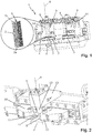
- the machine tool 1 shown is used for machining workpieces 2 and comprises a clamping device 3 for clamping a workpiece 2 to be machined and an axially only schematically indicated here and radially adjustable cutting tool 4 for machining the clamped workpiece 2.
- the workpiece 2 to be machined mostly as shown, a square prism blank, has a foot 2a and a head 2b with a welded-on cylindrical pin 5 .
- the clamping device 3 comprises a first central clamping device 7, which is rotatably mounted about an axis of rotation 6 , for clamping the foot 2a of the workpiece 2, a rotary drive 8 , which is only schematically indicated here, for rotating the first clamping device 7 about the axis of rotation 6, and one which is rotatable about the axis of rotation 6 mounted, second central clamping device 9 , for example in the form of a two-jaw chuck, for clamping the pin 5 of the workpiece 2.
- the rotary drive 8 is formed, for example, by a driven machine axis (C axis), as a result of which a high rigidity of the overall system is achieved.
- the second clamping device 9 is designed as a two-jaw chuck with two clamping jaws 10 , the clamping surfaces of which are each formed by two rollers 11, which are freely rotatable about an axis parallel to the axis of rotation 6.
- the clamping element 13 should advantageously be axially advanced at least to the level of the clamping jaws 10, better still at least to the level of the rollers 11, in order to rest on pins 5 of different lengths.
- the tensioning element 13 is freely rotatably mounted or likewise driven by the rotary drive 8 and can for example be designed as a tensioning cylinder.
- the second clamping device 9 and the axial clamping device 12 are fastened to one another in order to be able to be axially displaced approximately 100 mm as a unit in machine-side guides 14 by means of a spindle. As a result, the clamping device 3 can be converted to workpieces 2 of different lengths with little effort.
- the roughing and finishing operations of the workpiece 2 are thus carried out in the same clamping position of the workpiece 2 and can in particular be automated.
Landscapes
- Engineering & Computer Science (AREA)
- Mechanical Engineering (AREA)
- Jigs For Machine Tools (AREA)
Claims (8)
- Dispositif de serrage (3) dévolu à l'ablocage d'une pièce d'usinage (2) pouvant tourner autour d'un axe de rotation (6), munie d'une base (2a) et d'une tête (2b) comportant un tenon (5) notamment cylindrique, comprenant
un premier système de serrage (7) centré, monté rotatif autour de l'axe de rotation (6) et conçu pour abloquer la base (2a) de la pièce d'usinage (2),
un entraînement en rotation (8), conçu pour faire tourner ledit premier système de serrage (7) autour dudit axe de rotation (6),
un second système de serrage (9) centré, affecté au montage rotatif du tenon (5) de ladite pièce d'usinage (2) autour dudit axe de rotation (6), lequel second système de serrage (9) est pourvu de plusieurs mâchoires de serrage (10) dont les surfaces de serrage sont constituées, à chaque fois, d'au moins un galet (11) monté à rotation libre autour d'un axe parallèle audit axe de rotation (6), et
un système (12) de serrage axial, implanté du côté dudit second système de serrage (9) qui pointe à l'opposé dudit premier système de serrage (7), et doté d'un élément d'ablocage (13) monté rotatif autour dudit axe de rotation (6) et pouvant être poussé en avant, dans la direction axiale, jusqu'à venir frontalement en applique contre le tenon (5) d'une pièce d'usinage (2) enserrée dans ledit premier système de serrage (7), afin d'abloquer ladite pièce d'usinage (2) dans le sens axial,
caractérisé par le fait
que le second système de serrage (9) et le système (12) de serrage axial sont fixés l'un à l'autre et sont guidés avec faculté de déplacement axial, sous la forme d'un ensemble unitaire. - Dispositif de serrage selon la revendication 1, caractérisé par le fait que le premier système de serrage (7) est réalisé sous la forme d'un mandrin à mâchoires, en particulier d'un mandrin à deux mâchoires.
- Dispositif de serrage selon la revendication 1 ou 2, caractérisé par le fait que le second système de serrage (9) est réalisé sous la forme d'un mandrin à mâchoires, en particulier d'un mandrin à deux mâchoires comptant deux galets (11) pour chaque mâchoire de serrage (10).
- Dispositif de serrage selon l'une des revendications précédentes, caractérisé par le fait que l'élément d'ablocage (13) est réalisé sous la forme d'un cylindre d'ablocage.
- Dispositif de serrage selon l'une des revendications précédentes, caractérisé par le fait que l'élément d'ablocage (13) peut être poussé en avant, dans le sens axial, au moins jusqu'à la hauteur des mâchoires de serrage (10), en particulier au moins jusqu'à la hauteur des galets (11).
- Machine-outil (1) destinée à l'usinage de pièces (2) par enlèvement de copeaux, équipée d'un dispositif de serrage (3) conforme à l'une des revendications précédentes, dévolu à l'ablocage d'une pièce d'usinage (2), et d'un outil de coupe (4) pilotable axialement et radialement, affecté à l'usinage d'une pièce (2) enserrée.
- Machine-outil selon la revendication 6, caractérisée par le fait que l'entraînement en rotation (8) du dispositif de serrage (3) est constitué par un axe entraîné de ladite machine.
- Procédé d'usinage par enlèvement de copeaux, dans une machine-outil (1) conforme à la revendication 6 ou 7, de pièces (2) munies d'une base (2a) et d'une tête (2b) comportant un tenon (5) notamment cylindrique,
comprenant les étapes opératoires suivantes :- enserrement de la base (2a) de la pièce d'usinage (2) dans le premier système de serrage (7), suivi d'un enserrement axial de ladite pièce d'usinage (2) en poussant l'élément d'ablocage (13) en avant, jusqu'à la venue en applique frontale contre le tenon (5) de ladite pièce d'usinage (2) ;- usinage dudit tenon (5) avec enlèvement de copeaux, par rotation imprimée à ladite pièce d'usinage (2) et par pilotage de l'outil de coupe (4) jusqu'à ce que ledit tenon (5) soit centré vis-à-vis de l'axe de rotation (6) ;- enserrement dudit tenon (5) dans le second système de serrage (9), suivi d'un soulagement de l'enserrement axial de ladite pièce d'usinage (2) par poussée rétrograde exercée sur ledit élément d'ablocage (13) ;- usinage de ladite pièce (2) avec enlèvement de copeaux, notamment dégrossissage, par rotation imprimée à ladite pièce d'usinage (2) et par pilotage dudit outil de coupe (4) ;- enserrement axial de ladite pièce d'usinage (2) en poussant ledit élément d'ablocage (13) en avant, jusqu'à la venue en applique frontale contre ledit tenon (5), suivi d'un relâchement dudit second système de serrage (9) ;- usinage dudit tenon (5) avec enlèvement de copeaux, par rotation imprimée à ladite pièce d'usinage (2) et par pilotage dudit outil de coupe (4) jusqu'à ce que ledit tenon (5) soit centré vis-à-vis dudit axe de rotation (6) ;- enserrement dudit tenon (5) dans ledit second système de serrage (9), suivi d'un soulagement de l'enserrement axial par poussée rétrograde exercée sur ledit élément d'ablocage (13) ; et- usinage de ladite pièce (2) avec enlèvement de copeaux, notamment finissage, par rotation imprimée à ladite pièce d'usinage (2) et par pilotage dudit outil de coupe (4).
Priority Applications (2)
| Application Number | Priority Date | Filing Date | Title |
|---|---|---|---|
| EP17188552.8A EP3450089B1 (fr) | 2017-08-30 | 2017-08-30 | Dispositif et procédé pour serrage d'une pièce d'usinage montée à rotation |
| ES17188552T ES2801680T3 (es) | 2017-08-30 | 2017-08-30 | Dispositivo y procedimiento para la sujeción de una pieza de trabajo montada de manera giratoria |
Applications Claiming Priority (1)
| Application Number | Priority Date | Filing Date | Title |
|---|---|---|---|
| EP17188552.8A EP3450089B1 (fr) | 2017-08-30 | 2017-08-30 | Dispositif et procédé pour serrage d'une pièce d'usinage montée à rotation |
Publications (2)
| Publication Number | Publication Date |
|---|---|
| EP3450089A1 EP3450089A1 (fr) | 2019-03-06 |
| EP3450089B1 true EP3450089B1 (fr) | 2020-06-10 |
Family
ID=59895039
Family Applications (1)
| Application Number | Title | Priority Date | Filing Date |
|---|---|---|---|
| EP17188552.8A Active EP3450089B1 (fr) | 2017-08-30 | 2017-08-30 | Dispositif et procédé pour serrage d'une pièce d'usinage montée à rotation |
Country Status (2)
| Country | Link |
|---|---|
| EP (1) | EP3450089B1 (fr) |
| ES (1) | ES2801680T3 (fr) |
Family Cites Families (8)
| Publication number | Priority date | Publication date | Assignee | Title |
|---|---|---|---|---|
| US3225631A (en) * | 1963-11-22 | 1965-12-28 | Leblond Mach Tool Co R K | Self-adjusting steady rest roller |
| JPS5135588Y2 (fr) * | 1972-01-22 | 1976-09-01 | ||
| DE3809619A1 (de) * | 1988-03-22 | 1989-10-12 | Boehringer Werkzeugmaschinen | Verfahren und vorrichtung zur bearbeitung von rotationssymmetrischen bauteilen |
| US5222421A (en) * | 1992-01-24 | 1993-06-29 | Dainichi Kinzoku Kogyo Kabushiki Kaisha | Centering device |
| DE19749939C2 (de) * | 1997-11-11 | 2003-10-23 | Boehringer Werkzeugmaschinen | Verfahren zur Bearbeitung von Werkstücken |
| US6202520B1 (en) * | 1998-06-11 | 2001-03-20 | Car-Tec Company | Method and apparatus for machining highly concentric parts |
| US20040237734A1 (en) * | 2003-05-30 | 2004-12-02 | Lessway Richard J. | Vibration damper for rotating shaft |
| JP4163235B2 (ja) * | 2007-01-31 | 2008-10-08 | ヤマザキマザック株式会社 | ワーク加工装置 |
-
2017
- 2017-08-30 EP EP17188552.8A patent/EP3450089B1/fr active Active
- 2017-08-30 ES ES17188552T patent/ES2801680T3/es active Active
Non-Patent Citations (1)
| Title |
|---|
| None * |
Also Published As
| Publication number | Publication date |
|---|---|
| ES2801680T3 (es) | 2021-01-12 |
| EP3450089A1 (fr) | 2019-03-06 |
Similar Documents
| Publication | Publication Date | Title |
|---|---|---|
| EP0334298B1 (fr) | Méthode et dispositif d'usinage de pièces à symétrie rotative | |
| DE69228796T2 (de) | Nockenachsebearbeitungsmethode und Gerät | |
| DE19857359B4 (de) | Verfahren und Vorrichtung zum Bearbeiten von Werkstücken mit dünnwandigen Bereichen, die zentrische Formabweichungen aufweisen | |
| EP0714338B1 (fr) | Procede et dispositif permettant de rectifier un vilebrequin | |
| DE2633432C3 (de) | Vorrichtung zum zentrischen Spannen von ringförmigen Werkstücken für die Innenbearbeitung | |
| EP0273950B1 (fr) | Procede et dispositif de fabrication de pieces tournees coupees dans des barres | |
| DE102004043404A1 (de) | Verfahren zur Bearbeitung von Rotationsteilen | |
| EP1874496B1 (fr) | Dispositif de serrage | |
| EP1884303B1 (fr) | Procédé destiné à centrer des pièces à usiner tout comme dispositif destiné à la réalisation d'un tel procédé | |
| CH662964A5 (de) | Verfahren zur bearbeitung eines werkstuecks in einer drehmaschine zwischen spitzen sowie spannvorrichtung zur durchfuehrung dieses verfahrens. | |
| DE4123859C2 (de) | Verfahren zur spanenden Bearbeitung von Werkstücken mit rotationssymmetrischen Flächen, vorzugsweise von Kurbelwellen, und Vorrichtung zur Durchführung eines solchen Verfahrens | |
| DE102015121392A1 (de) | Werkzeughalter | |
| DE936176C (de) | Selbsttaetige Drehbank | |
| DE3400082C2 (fr) | ||
| EP3450089B1 (fr) | Dispositif et procédé pour serrage d'une pièce d'usinage montée à rotation | |
| DE102018116229B3 (de) | Spannvorrichtung, Werkzeugmaschine sowie Verfahren zum zweistufigen Spannen eines Werkstücks | |
| EP2198994A2 (fr) | Dispositif de centrage destiné à centrer une pièce usinée par rapport à un axe rotatif d'une machine-outil | |
| CH670788A5 (fr) | ||
| DE1259674B (de) | Langdrehautomat | |
| DE1752636A1 (de) | Vorrichtung zum Halten der Klemmbacken bei Drehbaenken od.dgl. | |
| DE2107791A1 (de) | Verfahren und Gerat fur das Be arbeiten von Rohren | |
| DE202006000290U1 (de) | Universalschleifmaschine | |
| DE2137396B2 (de) | Spanneinrichtung für Schneidwerkzeuge | |
| DE3844423C1 (en) | Method and apparatus for working wire-shaped or rod-shaped material | |
| DE838848C (de) | Mehrbackenzange |
Legal Events
| Date | Code | Title | Description |
|---|---|---|---|
| PUAI | Public reference made under article 153(3) epc to a published international application that has entered the european phase |
Free format text: ORIGINAL CODE: 0009012 |
|
| STAA | Information on the status of an ep patent application or granted ep patent |
Free format text: STATUS: REQUEST FOR EXAMINATION WAS MADE |
|
| 17P | Request for examination filed |
Effective date: 20180515 |
|
| AK | Designated contracting states |
Kind code of ref document: A1 Designated state(s): AL AT BE BG CH CY CZ DE DK EE ES FI FR GB GR HR HU IE IS IT LI LT LU LV MC MK MT NL NO PL PT RO RS SE SI SK SM TR |
|
| AX | Request for extension of the european patent |
Extension state: BA ME |
|
| GRAP | Despatch of communication of intention to grant a patent |
Free format text: ORIGINAL CODE: EPIDOSNIGR1 |
|
| STAA | Information on the status of an ep patent application or granted ep patent |
Free format text: STATUS: GRANT OF PATENT IS INTENDED |
|
| INTG | Intention to grant announced |
Effective date: 20200306 |
|
| GRAS | Grant fee paid |
Free format text: ORIGINAL CODE: EPIDOSNIGR3 |
|
| GRAA | (expected) grant |
Free format text: ORIGINAL CODE: 0009210 |
|
| STAA | Information on the status of an ep patent application or granted ep patent |
Free format text: STATUS: THE PATENT HAS BEEN GRANTED |
|
| AK | Designated contracting states |
Kind code of ref document: B1 Designated state(s): AL AT BE BG CH CY CZ DE DK EE ES FI FR GB GR HR HU IE IS IT LI LT LU LV MC MK MT NL NO PL PT RO RS SE SI SK SM TR |
|
| REG | Reference to a national code |
Ref country code: GB Ref legal event code: FG4D Free format text: NOT ENGLISH |
|
| REG | Reference to a national code |
Ref country code: CH Ref legal event code: EP Ref country code: AT Ref legal event code: REF Ref document number: 1278811 Country of ref document: AT Kind code of ref document: T Effective date: 20200615 |
|
| REG | Reference to a national code |
Ref country code: DE Ref legal event code: R082 Ref document number: 502017005631 Country of ref document: DE Representative=s name: KOHLER SCHMID MOEBUS PATENTANWAELTE PARTNERSCH, DE |
|
| REG | Reference to a national code |
Ref country code: DE Ref legal event code: R096 Ref document number: 502017005631 Country of ref document: DE |
|
| REG | Reference to a national code |
Ref country code: IE Ref legal event code: FG4D Free format text: LANGUAGE OF EP DOCUMENT: GERMAN |
|
| REG | Reference to a national code |
Ref country code: LT Ref legal event code: MG4D |
|
| PG25 | Lapsed in a contracting state [announced via postgrant information from national office to epo] |
Ref country code: GR Free format text: LAPSE BECAUSE OF FAILURE TO SUBMIT A TRANSLATION OF THE DESCRIPTION OR TO PAY THE FEE WITHIN THE PRESCRIBED TIME-LIMIT Effective date: 20200911 Ref country code: NO Free format text: LAPSE BECAUSE OF FAILURE TO SUBMIT A TRANSLATION OF THE DESCRIPTION OR TO PAY THE FEE WITHIN THE PRESCRIBED TIME-LIMIT Effective date: 20200910 Ref country code: SE Free format text: LAPSE BECAUSE OF FAILURE TO SUBMIT A TRANSLATION OF THE DESCRIPTION OR TO PAY THE FEE WITHIN THE PRESCRIBED TIME-LIMIT Effective date: 20200610 Ref country code: FI Free format text: LAPSE BECAUSE OF FAILURE TO SUBMIT A TRANSLATION OF THE DESCRIPTION OR TO PAY THE FEE WITHIN THE PRESCRIBED TIME-LIMIT Effective date: 20200610 Ref country code: LT Free format text: LAPSE BECAUSE OF FAILURE TO SUBMIT A TRANSLATION OF THE DESCRIPTION OR TO PAY THE FEE WITHIN THE PRESCRIBED TIME-LIMIT Effective date: 20200610 |
|
| REG | Reference to a national code |
Ref country code: NL Ref legal event code: MP Effective date: 20200610 |
|
| PG25 | Lapsed in a contracting state [announced via postgrant information from national office to epo] |
Ref country code: HR Free format text: LAPSE BECAUSE OF FAILURE TO SUBMIT A TRANSLATION OF THE DESCRIPTION OR TO PAY THE FEE WITHIN THE PRESCRIBED TIME-LIMIT Effective date: 20200610 Ref country code: RS Free format text: LAPSE BECAUSE OF FAILURE TO SUBMIT A TRANSLATION OF THE DESCRIPTION OR TO PAY THE FEE WITHIN THE PRESCRIBED TIME-LIMIT Effective date: 20200610 Ref country code: LV Free format text: LAPSE BECAUSE OF FAILURE TO SUBMIT A TRANSLATION OF THE DESCRIPTION OR TO PAY THE FEE WITHIN THE PRESCRIBED TIME-LIMIT Effective date: 20200610 Ref country code: BG Free format text: LAPSE BECAUSE OF FAILURE TO SUBMIT A TRANSLATION OF THE DESCRIPTION OR TO PAY THE FEE WITHIN THE PRESCRIBED TIME-LIMIT Effective date: 20200910 |
|
| PG25 | Lapsed in a contracting state [announced via postgrant information from national office to epo] |
Ref country code: NL Free format text: LAPSE BECAUSE OF FAILURE TO SUBMIT A TRANSLATION OF THE DESCRIPTION OR TO PAY THE FEE WITHIN THE PRESCRIBED TIME-LIMIT Effective date: 20200610 Ref country code: AL Free format text: LAPSE BECAUSE OF FAILURE TO SUBMIT A TRANSLATION OF THE DESCRIPTION OR TO PAY THE FEE WITHIN THE PRESCRIBED TIME-LIMIT Effective date: 20200610 |
|
| REG | Reference to a national code |
Ref country code: ES Ref legal event code: FG2A Ref document number: 2801680 Country of ref document: ES Kind code of ref document: T3 Effective date: 20210112 |
|
| PG25 | Lapsed in a contracting state [announced via postgrant information from national office to epo] |
Ref country code: PT Free format text: LAPSE BECAUSE OF FAILURE TO SUBMIT A TRANSLATION OF THE DESCRIPTION OR TO PAY THE FEE WITHIN THE PRESCRIBED TIME-LIMIT Effective date: 20201012 Ref country code: CZ Free format text: LAPSE BECAUSE OF FAILURE TO SUBMIT A TRANSLATION OF THE DESCRIPTION OR TO PAY THE FEE WITHIN THE PRESCRIBED TIME-LIMIT Effective date: 20200610 Ref country code: SM Free format text: LAPSE BECAUSE OF FAILURE TO SUBMIT A TRANSLATION OF THE DESCRIPTION OR TO PAY THE FEE WITHIN THE PRESCRIBED TIME-LIMIT Effective date: 20200610 Ref country code: EE Free format text: LAPSE BECAUSE OF FAILURE TO SUBMIT A TRANSLATION OF THE DESCRIPTION OR TO PAY THE FEE WITHIN THE PRESCRIBED TIME-LIMIT Effective date: 20200610 Ref country code: RO Free format text: LAPSE BECAUSE OF FAILURE TO SUBMIT A TRANSLATION OF THE DESCRIPTION OR TO PAY THE FEE WITHIN THE PRESCRIBED TIME-LIMIT Effective date: 20200610 |
|
| PG25 | Lapsed in a contracting state [announced via postgrant information from national office to epo] |
Ref country code: SK Free format text: LAPSE BECAUSE OF FAILURE TO SUBMIT A TRANSLATION OF THE DESCRIPTION OR TO PAY THE FEE WITHIN THE PRESCRIBED TIME-LIMIT Effective date: 20200610 Ref country code: PL Free format text: LAPSE BECAUSE OF FAILURE TO SUBMIT A TRANSLATION OF THE DESCRIPTION OR TO PAY THE FEE WITHIN THE PRESCRIBED TIME-LIMIT Effective date: 20200610 Ref country code: IS Free format text: LAPSE BECAUSE OF FAILURE TO SUBMIT A TRANSLATION OF THE DESCRIPTION OR TO PAY THE FEE WITHIN THE PRESCRIBED TIME-LIMIT Effective date: 20201010 |
|
| REG | Reference to a national code |
Ref country code: DE Ref legal event code: R097 Ref document number: 502017005631 Country of ref document: DE |
|
| PG25 | Lapsed in a contracting state [announced via postgrant information from national office to epo] |
Ref country code: MC Free format text: LAPSE BECAUSE OF FAILURE TO SUBMIT A TRANSLATION OF THE DESCRIPTION OR TO PAY THE FEE WITHIN THE PRESCRIBED TIME-LIMIT Effective date: 20200610 |
|
| REG | Reference to a national code |
Ref country code: CH Ref legal event code: PL |
|
| PLBE | No opposition filed within time limit |
Free format text: ORIGINAL CODE: 0009261 |
|
| STAA | Information on the status of an ep patent application or granted ep patent |
Free format text: STATUS: NO OPPOSITION FILED WITHIN TIME LIMIT |
|
| PG25 | Lapsed in a contracting state [announced via postgrant information from national office to epo] |
Ref country code: DK Free format text: LAPSE BECAUSE OF FAILURE TO SUBMIT A TRANSLATION OF THE DESCRIPTION OR TO PAY THE FEE WITHIN THE PRESCRIBED TIME-LIMIT Effective date: 20200610 Ref country code: CH Free format text: LAPSE BECAUSE OF NON-PAYMENT OF DUE FEES Effective date: 20200831 Ref country code: LI Free format text: LAPSE BECAUSE OF NON-PAYMENT OF DUE FEES Effective date: 20200831 Ref country code: LU Free format text: LAPSE BECAUSE OF NON-PAYMENT OF DUE FEES Effective date: 20200830 |
|
| 26N | No opposition filed |
Effective date: 20210311 |
|
| REG | Reference to a national code |
Ref country code: BE Ref legal event code: MM Effective date: 20200831 |
|
| PG25 | Lapsed in a contracting state [announced via postgrant information from national office to epo] |
Ref country code: SI Free format text: LAPSE BECAUSE OF FAILURE TO SUBMIT A TRANSLATION OF THE DESCRIPTION OR TO PAY THE FEE WITHIN THE PRESCRIBED TIME-LIMIT Effective date: 20200610 |
|
| PG25 | Lapsed in a contracting state [announced via postgrant information from national office to epo] |
Ref country code: BE Free format text: LAPSE BECAUSE OF NON-PAYMENT OF DUE FEES Effective date: 20200831 Ref country code: IE Free format text: LAPSE BECAUSE OF NON-PAYMENT OF DUE FEES Effective date: 20200830 |
|
| GBPC | Gb: european patent ceased through non-payment of renewal fee |
Effective date: 20210830 |
|
| PG25 | Lapsed in a contracting state [announced via postgrant information from national office to epo] |
Ref country code: TR Free format text: LAPSE BECAUSE OF FAILURE TO SUBMIT A TRANSLATION OF THE DESCRIPTION OR TO PAY THE FEE WITHIN THE PRESCRIBED TIME-LIMIT Effective date: 20200610 Ref country code: MT Free format text: LAPSE BECAUSE OF FAILURE TO SUBMIT A TRANSLATION OF THE DESCRIPTION OR TO PAY THE FEE WITHIN THE PRESCRIBED TIME-LIMIT Effective date: 20200610 Ref country code: CY Free format text: LAPSE BECAUSE OF FAILURE TO SUBMIT A TRANSLATION OF THE DESCRIPTION OR TO PAY THE FEE WITHIN THE PRESCRIBED TIME-LIMIT Effective date: 20200610 |
|
| PG25 | Lapsed in a contracting state [announced via postgrant information from national office to epo] |
Ref country code: MK Free format text: LAPSE BECAUSE OF FAILURE TO SUBMIT A TRANSLATION OF THE DESCRIPTION OR TO PAY THE FEE WITHIN THE PRESCRIBED TIME-LIMIT Effective date: 20200610 |
|
| PG25 | Lapsed in a contracting state [announced via postgrant information from national office to epo] |
Ref country code: GB Free format text: LAPSE BECAUSE OF NON-PAYMENT OF DUE FEES Effective date: 20210830 |
|
| PGFP | Annual fee paid to national office [announced via postgrant information from national office to epo] |
Ref country code: ES Payment date: 20250917 Year of fee payment: 9 |
|
| PGFP | Annual fee paid to national office [announced via postgrant information from national office to epo] |
Ref country code: DE Payment date: 20250825 Year of fee payment: 9 |
|
| PGFP | Annual fee paid to national office [announced via postgrant information from national office to epo] |
Ref country code: IT Payment date: 20250829 Year of fee payment: 9 |
|
| PGFP | Annual fee paid to national office [announced via postgrant information from national office to epo] |
Ref country code: FR Payment date: 20250821 Year of fee payment: 9 Ref country code: AT Payment date: 20250819 Year of fee payment: 9 |