EP3450805A1 - Mechanical seal - Google Patents
Mechanical seal Download PDFInfo
- Publication number
- EP3450805A1 EP3450805A1 EP17789310.4A EP17789310A EP3450805A1 EP 3450805 A1 EP3450805 A1 EP 3450805A1 EP 17789310 A EP17789310 A EP 17789310A EP 3450805 A1 EP3450805 A1 EP 3450805A1
- Authority
- EP
- European Patent Office
- Prior art keywords
- collar
- seal
- ring
- bellows
- mechanical seal
- Prior art date
- Legal status (The legal status is an assumption and is not a legal conclusion. Google has not performed a legal analysis and makes no representation as to the accuracy of the status listed.)
- Granted
Links
Images







Classifications
-
- F—MECHANICAL ENGINEERING; LIGHTING; HEATING; WEAPONS; BLASTING
- F16—ENGINEERING ELEMENTS AND UNITS; GENERAL MEASURES FOR PRODUCING AND MAINTAINING EFFECTIVE FUNCTIONING OF MACHINES OR INSTALLATIONS; THERMAL INSULATION IN GENERAL
- F16J—PISTONS; CYLINDERS; SEALINGS
- F16J15/00—Sealings
- F16J15/16—Sealings between relatively-moving surfaces
- F16J15/34—Sealings between relatively-moving surfaces with slip-ring pressed against a more or less radial face on one member
- F16J15/36—Sealings between relatively-moving surfaces with slip-ring pressed against a more or less radial face on one member connected by a diaphragm or bellow to the other member
- F16J15/363—Sealings between relatively-moving surfaces with slip-ring pressed against a more or less radial face on one member connected by a diaphragm or bellow to the other member the diaphragm or bellow being made of metal
-
- F—MECHANICAL ENGINEERING; LIGHTING; HEATING; WEAPONS; BLASTING
- F16—ENGINEERING ELEMENTS AND UNITS; GENERAL MEASURES FOR PRODUCING AND MAINTAINING EFFECTIVE FUNCTIONING OF MACHINES OR INSTALLATIONS; THERMAL INSULATION IN GENERAL
- F16J—PISTONS; CYLINDERS; SEALINGS
- F16J15/00—Sealings
- F16J15/16—Sealings between relatively-moving surfaces
- F16J15/34—Sealings between relatively-moving surfaces with slip-ring pressed against a more or less radial face on one member
- F16J15/3436—Pressing means
- F16J15/3452—Pressing means the pressing force resulting from the action of a spring
-
- F—MECHANICAL ENGINEERING; LIGHTING; HEATING; WEAPONS; BLASTING
- F16—ENGINEERING ELEMENTS AND UNITS; GENERAL MEASURES FOR PRODUCING AND MAINTAINING EFFECTIVE FUNCTIONING OF MACHINES OR INSTALLATIONS; THERMAL INSULATION IN GENERAL
- F16J—PISTONS; CYLINDERS; SEALINGS
- F16J15/00—Sealings
- F16J15/16—Sealings between relatively-moving surfaces
- F16J15/34—Sealings between relatively-moving surfaces with slip-ring pressed against a more or less radial face on one member
- F16J15/3464—Mounting of the seal
-
- F—MECHANICAL ENGINEERING; LIGHTING; HEATING; WEAPONS; BLASTING
- F16—ENGINEERING ELEMENTS AND UNITS; GENERAL MEASURES FOR PRODUCING AND MAINTAINING EFFECTIVE FUNCTIONING OF MACHINES OR INSTALLATIONS; THERMAL INSULATION IN GENERAL
- F16J—PISTONS; CYLINDERS; SEALINGS
- F16J15/00—Sealings
- F16J15/16—Sealings between relatively-moving surfaces
- F16J15/34—Sealings between relatively-moving surfaces with slip-ring pressed against a more or less radial face on one member
- F16J15/36—Sealings between relatively-moving surfaces with slip-ring pressed against a more or less radial face on one member connected by a diaphragm or bellow to the other member
-
- F—MECHANICAL ENGINEERING; LIGHTING; HEATING; WEAPONS; BLASTING
- F16—ENGINEERING ELEMENTS AND UNITS; GENERAL MEASURES FOR PRODUCING AND MAINTAINING EFFECTIVE FUNCTIONING OF MACHINES OR INSTALLATIONS; THERMAL INSULATION IN GENERAL
- F16J—PISTONS; CYLINDERS; SEALINGS
- F16J15/00—Sealings
- F16J15/16—Sealings between relatively-moving surfaces
- F16J15/34—Sealings between relatively-moving surfaces with slip-ring pressed against a more or less radial face on one member
- F16J15/38—Sealings between relatively-moving surfaces with slip-ring pressed against a more or less radial face on one member sealed by a packing
Definitions
- the present invention relates to a bellows mechanical seal.
- a bellows mechanical seal is configured to slide a seal ring and a mating ring in an axial direction to form a primary seal, thereby sealing a border between the inside and outside of the rings in a radial direction, disposed between a rotary shaft and a housing.
- a collar, a bellows, and the seal ring are arranged in the description this order on a seal ring side, an O-ring is disposed in an annular groove at the inner or outer periphery of the collar attached to one end of the bellows, and a secondary seal is formed between the collar and the rotary shaft or between the collar and the housing, thereby reducing leakage of sealing target fluid from the periphery of the collar.
- the bellows mechanical seal includes a stationary type bellows mechanical seal called a stationary type and configured such that a bellows is attached to a housing side, and a rotating type bellows mechanical seal called a rotating type and configured such that a bellows is attached to a rotary shaft side (these types of mechanical seals will be hereinafter merely referred to as a "stationary type” and a “rotating type”).
- an annular recessed portion is provided on each of an outer diameter side and an inner diameter side of a collar; an O-ring is disposed in the outer-diameter-side annular recessed portion of the collar in the case of the stationary type, and on the other hand, is disposed in the inner-diameter-side annular recessed portion of the collar in the case of the rotating type; and therefore, the common collar can be used for any of the stationary type and the rotating type (see, e.g., Patent Citation 1).
- Patent Citation 1 JP 4076626 (paragraph 0016, paragraph 0020, Fig. 2 , Fig. 3 )
- the annular recessed portion is provided on each of the outer and inner diameter sides, and the O-ring is disposed in one of the annular recessed portions.
- the collar needs a wall portion extending in a radial direction for formation of the annular recessed portion. For this reason, arrangement of the collar and the O-ring is limited because such arrangement depends on the shape of the collar.
- the present invention has been made focusing on the above-described problem, and is intended to provide a bellows mechanical seal with a high degree of freedom in arrangement of a collar and a secondary seal.
- the bellows mechanical seal is a bellows mechanical seal characterized by including a seal ring, a collar attached to the seal ring through a bellows, a mating ring slidably contacting the seal ring, and a secondary seal configured to seal a gap between the collar and a rotary shaft or between the collar and a housing.
- the collar has a restriction piece extending toward at least one of an inner diameter side and an outer diameter side.
- the bellows mechanical seal further includes an adaptor which is attached to the collar, whose axial movement is restricted by the restriction piece, and which extends to the inner diameter side or the outer diameter side over the restriction piece.
- the collar and the adaptor define at least part of a housing space having the secondary seal housed therein.
- the housing space can be changed according to the adaptor to be used, and therefore, the bellows mechanical seal with a high degree of freedom in arrangement of the collar and the secondary seal.
- the bellows mechanical seal according to a second aspect of the present invention is characterized in that the collar has the restriction piece extending to the inner diameter side and the outer diameter side.
- the adaptor is selectively attached to the inner-diameter-side or outer-diameter-side restriction piece.
- the bellows and the collar can be used for both of a rotating type and a stationary type, and a region occupied by the collar on a side not attached to the adaptor can be decreased.
- the bellows mechanical seal according to a third aspect of the present invention is characterized in that the restriction piece and the adaptor are in an endless annular shape.
- an allowance for engagement between the restriction piece and the adaptor is large, and these components can be supported with force being dispersed in a circumferential direction. Consequently, the restriction piece and the adaptor can be configured small.
- the bellows mechanical seal according to a fourth aspect of the present invention is characterized in that the adapter is provided with a step portion extending to an outer peripheral side or an inner peripheral side, and the restriction piece is brought into contact with the step portion in an axial direction.
- the restriction piece and the adaptor engage (so-called inlay engagement) with each other by the step. Consequently, an engagement state is stabilized.
- the bellows mechanical seal according to a fifth aspect of the present invention is characterized in that the collar is directly or indirectly fixed to the rotary shaft or the housing in the axial direction by a screwing member.
- the secondary seal can be, in a compressed state in the axial direction, attached directly or indirectly by the rotary shaft and the adaptor or by the housing and the adaptor.
- the bellows mechanical seal according to a sixth aspect of the present invention is characterized in that the secondary seal includes, as a main component, any of graphite, PTFE, and metal.
- the secondary seal can be attached from the opposite side of the restriction piece. This leads to favorable assembling performance.
- the direction of extending a rotary shaft axis is referred to as an "axial direction", and the direction perpendicular to the axis is referred to as a "radial direction.”
- axial direction the direction of extending a rotary shaft axis
- radial direction the direction perpendicular to the axis
- a sectional view of an annular member illustrates only a cut plane, and lines extending in the radial direction and indicating an uncut portion are not shown in each figure. Of both ends in the axial direction, a left end as viewed in the figure is described as one end, and a right end as viewed in the figure is described as the other end.
- the bellows mechanical seal 1 is attached between a rotary shaft 39 and a housing 40, and is configured to seal a space between the rotary shaft 39 and the housing 40.
- the bellows mechanical seal 1 mainly includes a collar 3, a bellows 13, a retainer 14, a seal ring 15, and a mating ring 17.
- the collar 3, the bellows 13, the retainer 14, and the seal ring 15 are integrally coupled together, thereby forming a bellows unit 2.
- the bellows unit 2 is common between a stationary type and a rotating type.
- Fig. 1A illustrating a secondary seal disposed on an outer diameter side will be described, and Fig. 1B illustrating the secondary seal disposed on an inner diameter side will not be described.
- the collar 3 is made of metal, and formed in an annular shape.
- the collar 3 is, at the inner and outer peripheries of one end portion in the axial direction, provided with an annular flange 4 (a restriction piece) extending in an outer diameter direction and an annular flange 8 (a restriction piece) extending in an inner diameter direction, as well as being provided with threaded screw holes 12 extending in the axial direction at the other end portion in the axial direction.
- the collar 3 may be made of other materials than the metal, such as resin.
- the bellows 13 is formed as follows: a plurality of metal diaphragm plates formed in a corrugated annular shape by punching etc. are arranged in line, and by gas welding etc., outer diameter portions of adjoining two of the diaphragm plates are coupled together and inner diameter portions of adjoining two of the diaphragm plates are coupled together; and then, the resultant is entirely formed in an annular bellows cylindrical shape.
- the other end of the bellows 13 is integrally coupled to the collar 3 by gas welding etc.
- the bellows 13 may be made of other materials than the metal, such as resin.
- the retainer 14 is made of metal, and is formed in an annular shape. One end portion of the retainer 14 on an inner peripheral side is provided with an annular step portion, and the outer periphery of the seal ring 15 is fitted into this step portion. The one end of the bellows 13 is integrally coupled to the retainer 14 by gas welding etc. Note that the retainer 14 may be made of other materials than the metal, such as resin.
- the seal ring 15 is made of carbon, and is formed in an annular shape. An outer peripheral side of the seal ring 15 is fitted into the step portion of the retainer 14 such that the seal ring 15 is integrally attached to the retainer 14. The one end of the seal ring 15 in the axial direction is provided with a seal face substantially perpendicular to the axial direction. Note that the seal ring 15 may be made of other materials than the carbon, such as metal or SiC (silicon carbide).
- the mating ring 17 (see Figs. 3 and 4 ) is made of SiC, and is formed in an annular shape. The one end of the mating ring 17 in the axial direction is provided with a seal face substantially perpendicular to the axial direction. Note that the mating ring 17 may be made of other materials than SiC, such as metal or carbon.
- the collar 3 is attached to the housing 40 through set screws 16 (screwing members) in a state in which an annular socket ring 50 (an adaptor) and an annular rectangular-sectional packing 60 (the secondary seal) are attached to the outer diameter side of the collar 3, and the mating ring 17 is attached to the rotary shaft 39 through a retainer 18, a connection ring 19, etc.
- the socket ring 50 is made of metal.
- the inner diameter side of the socket ring 50 on one end side in the axial direction is provided with an annular step portion 51.
- the socket ring 50 has a substantially L-shape section.
- An inner peripheral face 52 of the step portion 51 and an outer peripheral face 5 of the flange 4 are formed to have the substantially same diameter.
- the socket ring 50 can be fixed by press-fitting onto the collar 3 in the axial direction. In a state in which the socket ring 50 is attached to the collar 3, a side face 53 of the step portion 51 contacts a side face 6 of the flange 4 on the other end side, and therefore, the axial movement of the socket ring 50 toward the one end side is restricted.
- an outer peripheral face 7 of the collar 3, a side face 54 of the socket ring 50 on the other end side in the axial direction, an inner peripheral face 41 of the housing 40, and an inner face 42 of the housing 40 form a housing space S configured to house the rectangular-sectional packing 60 ( Fig. 4 ).
- the socket ring 50 may be made of other materials than the metal, such as resin.
- the rectangular-sectional packing 60 is formed with a rectangular section.
- a thickness T1 ( Fig. 1A ) as the axial length of the rectangular-sectional packing 60 is slightly greater than the axial length t1 (a distance between the side face 54 and the inner face 42) of the housing space S ( Fig. 4 ), and a radial width R1 as the radial length of the rectangular-sectional packing 60 is slightly smaller than the radial length r1 (a distance between the outer peripheral face 7 and the inner peripheral face 41) of the housing space S.
- the rectangular-sectional packing 60 is sandwiched by the side face 54 of the socket ring 50 and the inner face 42 of the housing 40, and is slightly compressed in the axial direction while slightly expanding in the radial direction.
- an inner peripheral face 64 contacts the outer peripheral face 7 of the collar 3, and an outer peripheral face 63 closely contacts the inner peripheral face 41 of the housing 40.
- the rectangular-sectional packing 60 has been described as an example of the secondary seal, but the shape/material of the secondary seal is not limited.
- the secondary seal is not limited to the secondary seal sandwiched by the side face 54 of the socket ring 50 and the inner face 42 of the housing 40, and may be a secondary seal held only between the inner peripheral face 41 of the housing 40 and the outer peripheral face 7 of the collar 3 in a compressed state.
- the secondary seal may be a seal (e.g., an annular seal having a C-shaped section) configured to deform, for sealing, by the pressure of sealing target fluid.
- a secondary seal exhibiting smaller contractibility/stretchability than those of the O-ring and mainly made of other materials than the rubber may be used.
- the secondary seal may be, for example, formed of an annular packing having a rectangular section in the case of using graphite as a main component, an annular V-packing having a V-shaped section or an annular X-ring having an X-shaped section in the case of using PTFE as the main component, and an annular seal having a C-shaped section or an annular metal ring having an E-shaped section in the case of using metal as the main component.
- a sleeve 37 is made of metal, and is formed in an annular shape.
- the sleeve 37 is, in a fixed manner, attached to the rotary shaft 39 through set screws 38.
- the connection ring 19 is made of metal, and is formed in an annular shape.
- the connection ring 19 is fixed to the sleeve 37 on the side close to the rotary shaft 39 through set screws 20.
- the retainer 18 is made of metal, and is formed in an annular shape.
- a knock pin 21 is disposed between the retainer 18 and the mating ring 17, and therefore, relative rotation of the mating ring 17 and the retainer 18 is restricted.
- the retainer 18 is fastened and fixed to the connection ring 19 by set screws 25 in a state in which a rectangular-sectional packing 22 is interposed between the retainer 18 and the connection ring 19, and therefore, seals the outside of the sleeve 37 disposed on the side close to the rotary shaft 39.
- the mating ring 17 is configured to seal a gap between the mating ring 17 and the retainer 18 by fitting an outer peripheral side of the mating ring 17 into an inner peripheral side of the retainer 18 in a state in which a rectangular-sectional packing 23 is interposed between the mating ring 17 and the retainer 18.
- the socket ring 50 and the rectangular-sectional packing 60 are attached in the description order from the other end side of the collar 3 in the axial direction.
- the sleeve 37 of the rotary shaft 39 is inserted to an inner peripheral side of the bellows unit 2, and the collar 3 is fitted into the housing 40.
- each set screw 16 is, in the axial direction, screwed and fastened into a corresponding one of the equally-arranged screw holes 12 (see Fig. 2 ) of the collar 3, and therefore, the collar 3 is fixed to the housing 40.
- the seal ring 15 is biased in the direction toward the mating ring 17 by the bellows 13, and the seal face of the seal ring 15 and the seal face of the mating ring 17 are pressed against each other.
- the bellows unit 2 is attached to the housing 40, and the mating ring 17 is attached to the rotary shaft 39.
- the seal face of the seal ring 15 and the seal face of the mating ring 17 slidably contact each other to function as a primary seal, and therefore, the space between the rotary shaft 39 and the housing 40 is sealed.
- the rectangular-sectional packing 60 functions as the secondary seal, and therefore, the space on a side close to the housing 40 is sealed.
- the rectangular-sectional packings 22, 23 each function as the secondary seal, and therefore, the space on a side close to the rotary shaft 39 is sealed.
- the housing 40 is provided with a baffle sleeve 45, a flow path 46, and an atmosphere-side sealing member 47, and therefore, a quenching solution can be introduced through the flow path 46.
- the collar 3 is attached to the rotary shaft 39 through the connection ring 19 etc. in a state in which an annular socket ring 70 (the adaptor) and an annular rectangular-sectional packing 80 (the secondary seal) are attached to the inner diameter side, and the mating ring 17 is attached to the housing 40.
- the socket ring 70 is provided with an annular step portion 71 on the outer diameter side on the other end side in the axial direction, and has a substantially L-shaped section. An inner peripheral face 72 of the step portion 71 and an outer peripheral face 9 of the flange 8 are formed to have the substantially same diameter.
- the socket ring 70 can be fixed onto the collar 3 by press-fitting in the axial direction. In a state in which the socket ring 70 is attached to the collar 3, a side face 73 of the step portion 71 contacts a side face 10 of the flange 8 on the one end side, and therefore, the axial movement of the socket ring 70 toward the one end side is restricted.
- an inner peripheral face 11 of the collar 3, a side face 74 of the socket ring 70 on the one end side in the axial direction, an outer peripheral face 36 of the sleeve 37, and a side face 35 of the connection ring 19 form a housing space S' configured to house the rectangular-sectional packing 80.
- the rectangular-sectional packing 80 is formed with a rectangular section.
- a dimensional relationship with the housing space S' is similar to that of the stationary type, and therefore, description thereof will not be repeated.
- the rectangular-sectional packing 80 has been described as an example of the secondary seal.
- the shape/material of the secondary seal is similar to that of the above-described stationary type, and therefore, description thereof will not be repeated.
- the material of the socket ring 70 is similar to that of the stationary type, and therefore, description thereof will not be repeated.
- the mating ring 17 is, by fitting in, attached to the housing 40.
- a rectangular-sectional packing 27 is disposed between the mating ring 17 and the housing 40, thereby forming the secondary seal.
- a knock pin 28 is disposed between the mating ring 17 and the housing 40, and therefore, relative rotation of the mating ring 17 and the housing 40 is restricted.
- connection ring 19 is fixed to the sleeve 37 through the set screws 20.
- the socket ring 70 and the rectangular-sectional packing 80 are attached in the description order from the one end side of the collar 3 in the axial direction.
- the sleeve 37 is inserted to the inner peripheral side of the bellows unit 2.
- each set screw 25 (a screwing member) is screwed and fastened into a corresponding one of the screw holes of the collar 3 from the one end side in the axial direction, and therefore, the collar 3 is fixed to the connection ring 19 on the side close to the rotary shaft 39.
- the seal ring 15 is biased in the direction toward the mating ring 17 by the bellows 13, and the seal face of the seal ring 15 and the seal face of the mating ring 17 are pressed against each other.
- the bellows unit 2 is attached to the rotary shaft 39, and the mating ring 17 is attached to the housing 40.
- the seal face of the seal ring 15 and the seal face of the mating ring 17 slidably contact each other to function as the primary seal, and therefore, the space between the rotary shaft 39 and the housing 40 is sealed.
- the rectangular-sectional packing 80 functions as the secondary seal, and therefore, the space on a side close to the rotary shaft 39 is sealed.
- the rectangular-sectional packing 27 functions as the secondary seal, and therefore, the space on a side close to the housing 40 is sealed.
- the socket ring 50 is disposed close to the seal ring 15 on an outer peripheral side of the collar 3, and therefore, the socket ring 50 is changed so that the housing space S of the rectangular-sectional packing 60 can be changed.
- the degree of freedom in arrangement of the collar 3 and the rectangular-sectional packing 60 is high.
- the housing space S' can be also changed in the case of the rotating type, and therefore, the degree of freedom in arrangement of the collar 3 and the rectangular-sectional packing 80 is high.
- the radial length of the flange 4, 8 of the collar 3 is short, and therefore, the size of the collar 3 is not increased in the radial direction.
- a space occupied by the collar 3 is small on a side on which the socket ring 50, 70 is not disposed, and therefore, the space between the rotary shaft 39 and the housing 40 can be effectively utilized.
- the radial length of the flange 8 of the collar 3 is short, and the socket ring 70, etc. are not arranged on the inner diameter side.
- the collar 3, the bellows 13 coupled to the collar 3, and the seal ring 15 can be downsized in the radial direction.
- the flanges 4, 8 are provided respectively on the inner and outer diameter sides of the collar 3, and therefore, the collar 3 can be shared between the stationary type and the rotating type. Further, the bellows 13 coupled to the collar 3 and the seal ring 15 can be also shared between the stationary type and the rotating type.
- the flanges 4, 8 on the inner and outer diameter sides of the collar 3 and the socket rings 50, 70 are in an endless annular shape.
- an engagement allowance in the axial direction is large, and these components can be supported with force being dispersed in the circumferential direction. Consequently, the flanges 4, 8 and the socket rings 50, 70 can be configured small.
- each of the step portions 51, 71 of the socket rings 50, 70 contacts a corresponding one of the flanges 4, 8 on the inner and outer diameter sides of the collar 3 in the axial direction.
- the flange 4, 8 and the socket ring 50, 70 engage (so-called inlay engagement) with each other by the step. Consequently, an engagement state is stabilized.
- the second embodiment of the bellows mechanical seal according to the present invention will be described with reference to Figs. 7 to 9 . Note that description of the same overlapping configurations as those of the first embodiment will not be repeated.
- the second embodiment is mainly different from the first embodiment in the configuration for restricting a socket ring in the axial direction.
- Annular recessed grooves 90, 92 are provided respectively at the inner and outer peripheries of a collar 3A.
- a C-ring 91 (a restriction piece) such as a snap ring having a rectangular section is fitted into the outer-diameter-side recessed groove 90, and axial movement of a socket ring 56 is restricted by the C-ring 91.
- a rectangular shape has been described as an example of the sectional shape of the socket ring 56, but the socket ring 56 may be provided with a step portion similar to that of the first embodiment such that engagement is made using the step portion. With this configuration, no portion protrudes inward in the radial direction of the collar 3A, leading to more size reduction of the collar 3A.
- a C-ring 93 (a restriction piece) having a rectangular section is fitted in the inner-diameter-side recessed groove 92, and axial movement of a socket ring 76 is restricted by this C-ring 93.
- the third embodiment of the bellows mechanical seal according to the present invention will be described with reference to Figs. 10 to 12 . Note that description of the same overlapping configurations as those of the first embodiment will not be repeated.
- the third embodiment is mainly different from the first embodiment in a configuration not using a rectangular-sectional packing.
- a collar 3B is provided with a flange 8 on an inner peripheral side, and forms a flat face on an outer peripheral side.
- an annular sheet-shaped gasket 95 mainly made of graphite is disposed between the other end face 29 of the collar 3B in the axial direction and a side end face 48 of a housing 40, thereby functioning as a secondary seal.
- a configuration similar to that of the first embodiment is employed. With this configuration, the collar 3B can be shared between the stationary type and the rotating type.
- the flange 8 is formed only on the inner peripheral side of the collar 3B has been described, but the flange may be formed only on the outer peripheral side of the collar.
- a variation of the third embodiment may be configured such that an annular groove 49 is provided at the side end face 48 of the housing 40 and a metal ring 96 (the secondary seal) is disposed in the annular groove 49 as illustrated in Fig. 13 .
- a plurality of protruding pieces 4c extending from an outer peripheral face 7C of a collar 3C in the outer diameter direction and having a predetermined length in the circumferential direction may be provided, and a plurality of protruding pieces 8c extending from an inner peripheral face 11C of the collar 3C in the inner diameter direction and having a predetermined length in the circumferential direction may be provided.
- protruding pieces 4d, 8d extending in a wave shape at the inner and outer peripheries of a collar 3D may be provided as illustrated in Fig. 14B . With these shapes, the weights of the collars 3C, 3D can be reduced.
- socket rings 50, 70 may be similarly changed.
- the socket ring 50, 56, 70, 76 may be or may not be fixed to the collar 3, 3A, 3B.
- fixing the socket ring 50, 56, 70, 76 such fixing is made by shrink fitting, cool fitting, bonding, welding, etc.
- the common bellows unit 2, 2A, 2B is preferably used between the stationary type and the rotating type because the number of components is reduced.
- it is not intended to exclude use of different bellows units for the stationary type and the rotating type. From a similar point of view, it is not intended to exclude a form in which the secondary seal is attached to an annular recessed groove.
Landscapes
- Engineering & Computer Science (AREA)
- General Engineering & Computer Science (AREA)
- Mechanical Engineering (AREA)
- Mechanical Sealing (AREA)
Abstract
Description
- The present invention relates to a bellows mechanical seal.
- A bellows mechanical seal is configured to slide a seal ring and a mating ring in an axial direction to form a primary seal, thereby sealing a border between the inside and outside of the rings in a radial direction, disposed between a rotary shaft and a housing. A collar, a bellows, and the seal ring are arranged in the description this order on a seal ring side, an O-ring is disposed in an annular groove at the inner or outer periphery of the collar attached to one end of the bellows, and a secondary seal is formed between the collar and the rotary shaft or between the collar and the housing, thereby reducing leakage of sealing target fluid from the periphery of the collar.
- The bellows mechanical seal includes a stationary type bellows mechanical seal called a stationary type and configured such that a bellows is attached to a housing side, and a rotating type bellows mechanical seal called a rotating type and configured such that a bellows is attached to a rotary shaft side (these types of mechanical seals will be hereinafter merely referred to as a "stationary type" and a "rotating type"). For reducing the number of components, it has been proposed as follows: an annular recessed portion is provided on each of an outer diameter side and an inner diameter side of a collar; an O-ring is disposed in the outer-diameter-side annular recessed portion of the collar in the case of the stationary type, and on the other hand, is disposed in the inner-diameter-side annular recessed portion of the collar in the case of the rotating type; and therefore, the common collar can be used for any of the stationary type and the rotating type (see, e.g., Patent Citation 1).
- Patent Citation 1:
JP 4076626 Fig. 2 ,Fig. 3 ) - However, in the typical collar, the annular recessed portion is provided on each of the outer and inner diameter sides, and the O-ring is disposed in one of the annular recessed portions. Thus, even on an annular recessed portion side on which the O-ring is not disposed, the collar needs a wall portion extending in a radial direction for formation of the annular recessed portion. For this reason, arrangement of the collar and the O-ring is limited because such arrangement depends on the shape of the collar.
- The present invention has been made focusing on the above-described problem, and is intended to provide a bellows mechanical seal with a high degree of freedom in arrangement of a collar and a secondary seal.
- For solving the above-described problem, the bellows mechanical seal according to a first aspect of the present invention is a bellows mechanical seal characterized by including a seal ring, a collar attached to the seal ring through a bellows, a mating ring slidably contacting the seal ring, and a secondary seal configured to seal a gap between the collar and a rotary shaft or between the collar and a housing. The collar has a restriction piece extending toward at least one of an inner diameter side and an outer diameter side. The bellows mechanical seal further includes an adaptor which is attached to the collar, whose axial movement is restricted by the restriction piece, and which extends to the inner diameter side or the outer diameter side over the restriction piece. The collar and the adaptor define at least part of a housing space having the secondary seal housed therein.
- According to the first aspect, the housing space can be changed according to the adaptor to be used, and therefore, the bellows mechanical seal with a high degree of freedom in arrangement of the collar and the secondary seal.
- The bellows mechanical seal according to a second aspect of the present invention is characterized in that the collar has the restriction piece extending to the inner diameter side and the outer diameter side.
- According to the second aspect, the adaptor is selectively attached to the inner-diameter-side or outer-diameter-side restriction piece. Thus, the bellows and the collar can be used for both of a rotating type and a stationary type, and a region occupied by the collar on a side not attached to the adaptor can be decreased.
- The bellows mechanical seal according to a third aspect of the present invention is characterized in that the restriction piece and the adaptor are in an endless annular shape.
- According to the third aspect, an allowance for engagement between the restriction piece and the adaptor is large, and these components can be supported with force being dispersed in a circumferential direction. Consequently, the restriction piece and the adaptor can be configured small.
- The bellows mechanical seal according to a fourth aspect of the present invention is characterized in that the adapter is provided with a step portion extending to an outer peripheral side or an inner peripheral side, and the restriction piece is brought into contact with the step portion in an axial direction.
- According to the fourth aspect, the restriction piece and the adaptor engage (so-called inlay engagement) with each other by the step. Consequently, an engagement state is stabilized.
- The bellows mechanical seal according to a fifth aspect of the present invention is characterized in that the collar is directly or indirectly fixed to the rotary shaft or the housing in the axial direction by a screwing member.
- According to the fifth aspect, the secondary seal can be, in a compressed state in the axial direction, attached directly or indirectly by the rotary shaft and the adaptor or by the housing and the adaptor.
- The bellows mechanical seal according to a sixth aspect of the present invention is characterized in that the secondary seal includes, as a main component, any of graphite, PTFE, and metal.
- According to the sixth aspect, even in the case of a secondary seal exhibiting less elasticity than that of a secondary seal using rubber as the main component, the secondary seal can be attached from the opposite side of the restriction piece. This leads to favorable assembling performance.
-
-
Fig. 1 is a sectional view showing a bellows unit of a first embodiment of the bellows mechanical seal according to the present invention,Fig. 1A being a sectional view of the bellows unit including a secondary seal attached to an outer diameter side of a collar andFig. 1B being a sectional view of the bellows unit including a secondary seal attached to an inner diameter side of the collar. -
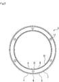
Fig. 2 is a sectional view of the collar ofFig. 1 along an arrow A. -
Fig. 3 is a sectional view of an example of the first embodiment in use for a stationary bellows mechanical seal. -
Fig. 4 is a sectional view of a main portion ofFig. 3 . -
Fig. 5 is a sectional view of another example of the first embodiment in use for a rotating type bellows mechanical seal. -
Fig. 6 is a sectional view of a main portion ofFig. 5 . -
Fig. 7 is a sectional view showing a bellows unit of a second embodiment of the bellows mechanical seal according to the present invention. -
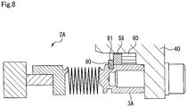
Fig. 8 is a sectional view of a main portion of a stationary type bellows mechanical seal in the second embodiment. -
Fig. 9 is a sectional view of a main portion of a rotating type bellows mechanical seal in the second embodiment. -
Fig. 10 is a sectional view showing a bellows unit of a third embodiment of the bellows mechanical seal according to the present invention. -
Fig. 11 is a sectional view of a main portion of a stationary type bellows mechanical seal in the third embodiment. -
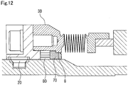
Fig. 12 is a sectional view of a main portion of a rotating type bellows mechanical seal in the third embodiment. -
Fig. 13 is a sectional view of a main portion of a stationary type bellows mechanical seal of a variation of the third embodiment. -
Fig. 14 is a view for describing variations of the collar in the first to third embodiments. - The embodiments of the bellows mechanical seal according to the present invention will be described below with reference to examples. In the embodiments, the direction of extending a rotary shaft axis is referred to as an "axial direction", and the direction perpendicular to the axis is referred to as a "radial direction." Moreover, for the sake of convenience of description, a sectional view of an annular member illustrates only a cut plane, and lines extending in the radial direction and indicating an uncut portion are not shown in each figure. Of both ends in the axial direction, a left end as viewed in the figure is described as one end, and a right end as viewed in the figure is described as the other end.
- The first embodiment of the bellows mechanical seal according to the present invention will be described with reference to
Figs. 1 to 6 . - The bellows mechanical seal 1 is attached between a
rotary shaft 39 and ahousing 40, and is configured to seal a space between therotary shaft 39 and thehousing 40. The bellows mechanical seal 1 mainly includes acollar 3, abellows 13, aretainer 14, aseal ring 15, and amating ring 17. Thecollar 3, thebellows 13, theretainer 14, and theseal ring 15 are integrally coupled together, thereby forming abellows unit 2. Note that thebellows unit 2 is common between a stationary type and a rotating type.Fig. 1A illustrating a secondary seal disposed on an outer diameter side will be described, andFig. 1B illustrating the secondary seal disposed on an inner diameter side will not be described. - As illustrated in
Fig. 2 , thecollar 3 is made of metal, and formed in an annular shape. Thecollar 3 is, at the inner and outer peripheries of one end portion in the axial direction, provided with an annular flange 4 (a restriction piece) extending in an outer diameter direction and an annular flange 8 (a restriction piece) extending in an inner diameter direction, as well as being provided with threaded screw holes 12 extending in the axial direction at the other end portion in the axial direction. Note that thecollar 3 may be made of other materials than the metal, such as resin. - The bellows 13 is formed as follows: a plurality of metal diaphragm plates formed in a corrugated annular shape by punching etc. are arranged in line, and by gas welding etc., outer diameter portions of adjoining two of the diaphragm plates are coupled together and inner diameter portions of adjoining two of the diaphragm plates are coupled together; and then, the resultant is entirely formed in an annular bellows cylindrical shape. The other end of the
bellows 13 is integrally coupled to thecollar 3 by gas welding etc. Note that thebellows 13 may be made of other materials than the metal, such as resin. - The
retainer 14 is made of metal, and is formed in an annular shape. One end portion of theretainer 14 on an inner peripheral side is provided with an annular step portion, and the outer periphery of theseal ring 15 is fitted into this step portion. The one end of thebellows 13 is integrally coupled to theretainer 14 by gas welding etc. Note that theretainer 14 may be made of other materials than the metal, such as resin. - The
seal ring 15 is made of carbon, and is formed in an annular shape. An outer peripheral side of theseal ring 15 is fitted into the step portion of theretainer 14 such that theseal ring 15 is integrally attached to theretainer 14. The one end of theseal ring 15 in the axial direction is provided with a seal face substantially perpendicular to the axial direction. Note that theseal ring 15 may be made of other materials than the carbon, such as metal or SiC (silicon carbide). - The mating ring 17 (see
Figs. 3 and4 ) is made of SiC, and is formed in an annular shape. The one end of themating ring 17 in the axial direction is provided with a seal face substantially perpendicular to the axial direction. Note that themating ring 17 may be made of other materials than SiC, such as metal or carbon. - Next, the case of using the bellows mechanical seal 1 as the stationary type will be described mainly with reference to
Figs. 1A ,2 ,3 , and4 . - The
collar 3 is attached to thehousing 40 through set screws 16 (screwing members) in a state in which an annular socket ring 50 (an adaptor) and an annular rectangular-sectional packing 60 (the secondary seal) are attached to the outer diameter side of thecollar 3, and themating ring 17 is attached to therotary shaft 39 through aretainer 18, aconnection ring 19, etc. - The
socket ring 50 is made of metal. The inner diameter side of thesocket ring 50 on one end side in the axial direction is provided with an annular step portion 51. Thesocket ring 50 has a substantially L-shape section. An innerperipheral face 52 of the step portion 51 and an outerperipheral face 5 of theflange 4 are formed to have the substantially same diameter. Thesocket ring 50 can be fixed by press-fitting onto thecollar 3 in the axial direction. In a state in which thesocket ring 50 is attached to thecollar 3, aside face 53 of the step portion 51 contacts aside face 6 of theflange 4 on the other end side, and therefore, the axial movement of thesocket ring 50 toward the one end side is restricted. Moreover, an outerperipheral face 7 of thecollar 3, aside face 54 of thesocket ring 50 on the other end side in the axial direction, an innerperipheral face 41 of thehousing 40, and aninner face 42 of thehousing 40 form a housing space S configured to house the rectangular-sectional packing 60 (Fig. 4 ). Note that thesocket ring 50 may be made of other materials than the metal, such as resin. - The rectangular-
sectional packing 60 is formed with a rectangular section. A thickness T1 (Fig. 1A ) as the axial length of the rectangular-sectional packing 60 is slightly greater than the axial length t1 (a distance between theside face 54 and the inner face 42) of the housing space S (Fig. 4 ), and a radial width R1 as the radial length of the rectangular-sectional packing 60 is slightly smaller than the radial length r1 (a distance between the outerperipheral face 7 and the inner peripheral face 41) of the housing space S. By tightening of theset screws 16, the rectangular-sectional packing 60 is sandwiched by theside face 54 of thesocket ring 50 and theinner face 42 of thehousing 40, and is slightly compressed in the axial direction while slightly expanding in the radial direction. Of the rectangular-sectional packing 60, an innerperipheral face 64 contacts the outerperipheral face 7 of thecollar 3, and an outerperipheral face 63 closely contacts the innerperipheral face 41 of thehousing 40. - Note that the rectangular-
sectional packing 60 has been described as an example of the secondary seal, but the shape/material of the secondary seal is not limited. Moreover, the secondary seal is not limited to the secondary seal sandwiched by theside face 54 of thesocket ring 50 and theinner face 42 of thehousing 40, and may be a secondary seal held only between the innerperipheral face 41 of thehousing 40 and the outerperipheral face 7 of thecollar 3 in a compressed state. Further, the secondary seal may be a seal (e.g., an annular seal having a C-shaped section) configured to deform, for sealing, by the pressure of sealing target fluid. - Moreover, in the case of sealing a fluid to which an O-ring mainly made of rubber is not applicable, a secondary seal exhibiting smaller contractibility/stretchability than those of the O-ring and mainly made of other materials than the rubber may be used. The secondary seal may be, for example, formed of an annular packing having a rectangular section in the case of using graphite as a main component, an annular V-packing having a V-shaped section or an annular X-ring having an X-shaped section in the case of using PTFE as the main component, and an annular seal having a C-shaped section or an annular metal ring having an E-shaped section in the case of using metal as the main component.
- Next, components directly or indirectly fixed to the
rotary shaft 39 will be described. - A
sleeve 37 is made of metal, and is formed in an annular shape. Thesleeve 37 is, in a fixed manner, attached to therotary shaft 39 throughset screws 38. Theconnection ring 19 is made of metal, and is formed in an annular shape. Theconnection ring 19 is fixed to thesleeve 37 on the side close to therotary shaft 39 throughset screws 20. Theretainer 18 is made of metal, and is formed in an annular shape. Aknock pin 21 is disposed between theretainer 18 and themating ring 17, and therefore, relative rotation of themating ring 17 and theretainer 18 is restricted. - The
retainer 18 is fastened and fixed to theconnection ring 19 byset screws 25 in a state in which a rectangular-sectional packing 22 is interposed between theretainer 18 and theconnection ring 19, and therefore, seals the outside of thesleeve 37 disposed on the side close to therotary shaft 39. Moreover, themating ring 17 is configured to seal a gap between themating ring 17 and theretainer 18 by fitting an outer peripheral side of themating ring 17 into an inner peripheral side of theretainer 18 in a state in which a rectangular-sectional packing 23 is interposed between themating ring 17 and theretainer 18. - Next, an entire configuration of the bellows mechanical seal will be described.
- The
socket ring 50 and the rectangular-sectional packing 60 are attached in the description order from the other end side of thecollar 3 in the axial direction. In this state, thesleeve 37 of therotary shaft 39 is inserted to an inner peripheral side of thebellows unit 2, and thecollar 3 is fitted into thehousing 40. Then, eachset screw 16 is, in the axial direction, screwed and fastened into a corresponding one of the equally-arranged screw holes 12 (seeFig. 2 ) of thecollar 3, and therefore, thecollar 3 is fixed to thehousing 40. Theseal ring 15 is biased in the direction toward themating ring 17 by thebellows 13, and the seal face of theseal ring 15 and the seal face of themating ring 17 are pressed against each other. - As described above, the
bellows unit 2 is attached to thehousing 40, and themating ring 17 is attached to therotary shaft 39. In this state, when therotary shaft 39 rotates, the seal face of theseal ring 15 and the seal face of themating ring 17 slidably contact each other to function as a primary seal, and therefore, the space between therotary shaft 39 and thehousing 40 is sealed. - Moreover, the rectangular-
sectional packing 60 functions as the secondary seal, and therefore, the space on a side close to thehousing 40 is sealed. The rectangular-sectional packings rotary shaft 39 is sealed. - Further, the
housing 40 is provided with abaffle sleeve 45, aflow path 46, and an atmosphere-side sealing member 47, and therefore, a quenching solution can be introduced through theflow path 46. - Next, the case of using the bellows mechanical seal 1 as the rotating type will be described mainly with reference to
Figs. 1B ,2 ,5 , and6 . Note that description of configurations similar to those of the stationary type will not be repeated. - The
collar 3 is attached to therotary shaft 39 through theconnection ring 19 etc. in a state in which an annular socket ring 70 (the adaptor) and an annular rectangular-sectional packing 80 (the secondary seal) are attached to the inner diameter side, and themating ring 17 is attached to thehousing 40. - The
socket ring 70 is provided with anannular step portion 71 on the outer diameter side on the other end side in the axial direction, and has a substantially L-shaped section. An innerperipheral face 72 of thestep portion 71 and an outerperipheral face 9 of theflange 8 are formed to have the substantially same diameter. Thesocket ring 70 can be fixed onto thecollar 3 by press-fitting in the axial direction. In a state in which thesocket ring 70 is attached to thecollar 3, aside face 73 of thestep portion 71 contacts aside face 10 of theflange 8 on the one end side, and therefore, the axial movement of thesocket ring 70 toward the one end side is restricted. Moreover, an innerperipheral face 11 of thecollar 3, aside face 74 of thesocket ring 70 on the one end side in the axial direction, an outerperipheral face 36 of thesleeve 37, and aside face 35 of theconnection ring 19 form a housing space S' configured to house the rectangular-sectional packing 80. - The rectangular-
sectional packing 80 is formed with a rectangular section. A dimensional relationship with the housing space S' is similar to that of the stationary type, and therefore, description thereof will not be repeated. Moreover, the rectangular-sectional packing 80 has been described as an example of the secondary seal. However, the shape/material of the secondary seal is similar to that of the above-described stationary type, and therefore, description thereof will not be repeated. Further, the material of thesocket ring 70 is similar to that of the stationary type, and therefore, description thereof will not be repeated. - The
mating ring 17 is, by fitting in, attached to thehousing 40. A rectangular-sectional packing 27 is disposed between themating ring 17 and thehousing 40, thereby forming the secondary seal. Moreover, aknock pin 28 is disposed between themating ring 17 and thehousing 40, and therefore, relative rotation of themating ring 17 and thehousing 40 is restricted. - The
connection ring 19 is fixed to thesleeve 37 through the set screws 20. Thesocket ring 70 and the rectangular-sectional packing 80 are attached in the description order from the one end side of thecollar 3 in the axial direction. In this state, thesleeve 37 is inserted to the inner peripheral side of thebellows unit 2. Then, each set screw 25 (a screwing member) is screwed and fastened into a corresponding one of the screw holes of thecollar 3 from the one end side in the axial direction, and therefore, thecollar 3 is fixed to theconnection ring 19 on the side close to therotary shaft 39. Theseal ring 15 is biased in the direction toward themating ring 17 by thebellows 13, and the seal face of theseal ring 15 and the seal face of themating ring 17 are pressed against each other. - As described above, the
bellows unit 2 is attached to therotary shaft 39, and themating ring 17 is attached to thehousing 40. In this state, when therotary shaft 39 rotates, the seal face of theseal ring 15 and the seal face of themating ring 17 slidably contact each other to function as the primary seal, and therefore, the space between therotary shaft 39 and thehousing 40 is sealed. - Moreover, the rectangular-
sectional packing 80 functions as the secondary seal, and therefore, the space on a side close to therotary shaft 39 is sealed. The rectangular-sectional packing 27 functions as the secondary seal, and therefore, the space on a side close to thehousing 40 is sealed. - In the case of the stationary type bellows mechanical seal 1 described above, the
socket ring 50 is disposed close to theseal ring 15 on an outer peripheral side of thecollar 3, and therefore, thesocket ring 50 is changed so that the housing space S of the rectangular-sectional packing 60 can be changed. Thus, the degree of freedom in arrangement of thecollar 3 and the rectangular-sectional packing 60 is high. As in the stationary type, the housing space S' can be also changed in the case of the rotating type, and therefore, the degree of freedom in arrangement of thecollar 3 and the rectangular-sectional packing 80 is high. - Further, the radial length of the
flange collar 3 is short, and therefore, the size of thecollar 3 is not increased in the radial direction. A space occupied by thecollar 3 is small on a side on which thesocket ring rotary shaft 39 and thehousing 40 can be effectively utilized. - In addition, in the case of the stationary type, the radial length of the
flange 8 of thecollar 3 is short, and thesocket ring 70, etc. are not arranged on the inner diameter side. Thus, thecollar 3, thebellows 13 coupled to thecollar 3, and theseal ring 15 can be downsized in the radial direction. - Moreover, the
flanges collar 3, and therefore, thecollar 3 can be shared between the stationary type and the rotating type. Further, thebellows 13 coupled to thecollar 3 and theseal ring 15 can be also shared between the stationary type and the rotating type. - Further, the
flanges collar 3 and the socket rings 50, 70 are in an endless annular shape. Thus, an engagement allowance in the axial direction is large, and these components can be supported with force being dispersed in the circumferential direction. Consequently, theflanges - In addition, each of the
step portions 51, 71 of the socket rings 50, 70 contacts a corresponding one of theflanges collar 3 in the axial direction. Thus, theflange socket ring - Next, the second embodiment of the bellows mechanical seal according to the present invention will be described with reference to
Figs. 7 to 9 . Note that description of the same overlapping configurations as those of the first embodiment will not be repeated. The second embodiment is mainly different from the first embodiment in the configuration for restricting a socket ring in the axial direction. - Annular recessed
grooves collar 3A. In the case of a stationary type, a C-ring 91 (a restriction piece) such as a snap ring having a rectangular section is fitted into the outer-diameter-side recessedgroove 90, and axial movement of asocket ring 56 is restricted by the C-ring 91. Note that a rectangular shape has been described as an example of the sectional shape of thesocket ring 56, but thesocket ring 56 may be provided with a step portion similar to that of the first embodiment such that engagement is made using the step portion. With this configuration, no portion protrudes inward in the radial direction of thecollar 3A, leading to more size reduction of thecollar 3A. - In the case of a rotating type, a C-ring 93 (a restriction piece) having a rectangular section is fitted in the inner-diameter-side recessed
groove 92, and axial movement of asocket ring 76 is restricted by this C-ring 93. - Next, the third embodiment of the bellows mechanical seal according to the present invention will be described with reference to
Figs. 10 to 12 . Note that description of the same overlapping configurations as those of the first embodiment will not be repeated. The third embodiment is mainly different from the first embodiment in a configuration not using a rectangular-sectional packing. - A
collar 3B is provided with aflange 8 on an inner peripheral side, and forms a flat face on an outer peripheral side. In the case of a stationary type, an annular sheet-shapedgasket 95 mainly made of graphite is disposed between the other end face 29 of thecollar 3B in the axial direction and a side end face 48 of ahousing 40, thereby functioning as a secondary seal. In the case of a rotating type, a configuration similar to that of the first embodiment is employed. With this configuration, thecollar 3B can be shared between the stationary type and the rotating type. - Note that in the third embodiment, the example where the
flange 8 is formed only on the inner peripheral side of thecollar 3B has been described, but the flange may be formed only on the outer peripheral side of the collar. - A variation of the third embodiment may be configured such that an
annular groove 49 is provided at the side end face 48 of thehousing 40 and a metal ring 96 (the secondary seal) is disposed in theannular groove 49 as illustrated inFig. 13 . - The embodiments of the present invention have been described above with reference to the drawings, but specific configurations are not limited to these embodiments. The present invention also includes changes and additions made without departing from the gist of the present invention.
- In the first to third embodiments, the cases where any of the
flanges collars Fig. 14A , a plurality of protrudingpieces 4c extending from an outerperipheral face 7C of acollar 3C in the outer diameter direction and having a predetermined length in the circumferential direction may be provided, and a plurality of protrudingpieces 8c extending from an innerperipheral face 11C of thecollar 3C in the inner diameter direction and having a predetermined length in the circumferential direction may be provided. Alternatively, protrudingpieces collar 3D may be provided as illustrated inFig. 14B . With these shapes, the weights of thecollars - Note that the shapes of the socket rings 50, 70 may be similarly changed.
- Moreover, in the first to third embodiments, the
socket ring collar socket ring - Further, in the first to third embodiments, the
common bellows unit -
- 1 bellows mechanical seal
- 2, 2A, 2B bellows unit
- 3, 3A, 3B, 3C, 3D collar
- 4 flange (restriction piece)
- 4c, 4d protruding piece (restriction piece)
- 8 flange (restriction piece)
- 8c, 8d protruding piece (restriction piece)
- 13 bellows
- 15 seal ring
- 16, 25 set screw (screwing member)
- 17 mating ring
- 36 outer peripheral face
- 37 sleeve
- 39 rotary shaft
- 40 housing
- 41 inner peripheral face
- 42 inner face
- 48 side end face
- 50, 56, 70, 76 socket ring (adaptor)
- 51, 71 step portion
- 52, 72 inner peripheral face
- 53, 54, 73, 74 side face
- 60, 80 rectangular-sectional packing (secondary seal)
- 63 outer peripheral face
- 64 inner peripheral face
- 90, 92 recessed groove
- 91, 93 C-ring (restriction piece)
- 95 gasket (secondary seal)
- 96 metal ring (secondary seal)
- R1 radial width
- S, S' housing space
Claims (6)
- A bellows mechanical seal characterized by comprising:a seal ring;a collar attached to the seal ring through a bellows;a mating ring slidably contacting the seal ring; anda secondary seal configured to seal a gap between the collar and a rotary shaft or between the collar and a housing,wherein the collar has a restriction piece extending toward at least one of an inner diameter side and an outer diameter side,the bellows mechanical seal further includes an adaptor which is attached to the collar, whose axial movement is restricted by the restriction piece, and which extends to the inner diameter side or the outer diameter side over the restriction piece, andthe collar and the adaptor define at least part of a housing space having the secondary seal housed therein.
- The bellows mechanical seal according to claim 1, characterized in that
the collar has the restriction piece extending to the inner diameter side and the outer diameter side. - The bellows mechanical seal according to claim 1 or 2, characterized in that
the restriction piece and the adaptor are in an endless annular shape. - The bellows mechanical seal according to any one of claims 1 to 3, characterized in that
the adapter is provided with a step portion extending to an outer peripheral side or an inner peripheral side, and
the restriction piece is brought into contact with the step portion in an axial direction. - The bellows mechanical seal according to any one of claims 1 to 4, characterized in that
the collar is directly or indirectly fixed to the rotary shaft or the housing in the axial direction by a screwing member. - The bellows mechanical seal according to any one of claims 1 to 5, characterized in that
the secondary seal includes, as a main component, any of graphite, PTFE, and metal.
Applications Claiming Priority (2)
| Application Number | Priority Date | Filing Date | Title |
|---|---|---|---|
| JP2016089536 | 2016-04-27 | ||
| PCT/JP2017/015254 WO2017188024A1 (en) | 2016-04-27 | 2017-04-14 | Mechanical seal |
Publications (3)
| Publication Number | Publication Date |
|---|---|
| EP3450805A1 true EP3450805A1 (en) | 2019-03-06 |
| EP3450805A4 EP3450805A4 (en) | 2019-12-11 |
| EP3450805B1 EP3450805B1 (en) | 2024-02-07 |
Family
ID=60161474
Family Applications (1)
| Application Number | Title | Priority Date | Filing Date |
|---|---|---|---|
| EP17789310.4A Active EP3450805B1 (en) | 2016-04-27 | 2017-04-14 | Mechanical seal |
Country Status (5)
| Country | Link |
|---|---|
| US (1) | US10883606B2 (en) |
| EP (1) | EP3450805B1 (en) |
| JP (1) | JP6795586B2 (en) |
| CN (1) | CN109073090B (en) |
| WO (1) | WO2017188024A1 (en) |
Cited By (2)
| Publication number | Priority date | Publication date | Assignee | Title |
|---|---|---|---|---|
| GB2603761A (en) * | 2021-02-10 | 2022-08-17 | Aes Eng Ltd | Mechanical seal bellows |
| WO2023041242A1 (en) * | 2021-09-17 | 2023-03-23 | Eagleburgmann Germany Gmbh & Co. Kg | Mechanical end-face seal assembly with improved axial force support |
Families Citing this family (8)
| Publication number | Priority date | Publication date | Assignee | Title |
|---|---|---|---|---|
| WO2020013156A1 (en) | 2018-07-12 | 2020-01-16 | イーグル工業株式会社 | Capacity control valve |
| CN112534136A (en) | 2018-08-08 | 2021-03-19 | 伊格尔工业股份有限公司 | Capacity control valve |
| JP7289603B2 (en) | 2018-08-08 | 2023-06-12 | イーグル工業株式会社 | capacity control valve |
| EP3916224B1 (en) * | 2019-01-21 | 2024-07-10 | Eagle Industry Co., Ltd. | Capacity control valve |
| EP3951172B1 (en) | 2019-04-03 | 2024-08-28 | Eagle Industry Co., Ltd. | Capacity control valve |
| WO2020235632A1 (en) * | 2019-05-23 | 2020-11-26 | イーグルブルグマンジャパン株式会社 | Mechanical seal |
| CN115427684B (en) | 2020-04-23 | 2025-08-05 | 伊格尔工业股份有限公司 | Capacity control valve |
| CN114776807A (en) * | 2022-04-12 | 2022-07-22 | 西安热工研究院有限公司 | Mechanical sealing structure capable of rapidly replacing graphite ring |
Family Cites Families (14)
| Publication number | Priority date | Publication date | Assignee | Title |
|---|---|---|---|---|
| US6311983B1 (en) * | 1989-09-26 | 2001-11-06 | The Boeing Company | Combination static lift-off face contact seal and floating ring shaft seal |
| JPH068868A (en) | 1992-06-24 | 1994-01-18 | Suzuki Motor Corp | Motorcycle frame |
| JPH083762Y2 (en) * | 1992-07-13 | 1996-01-31 | 日本ピラー工業株式会社 | mechanical seal |
| US5551708A (en) | 1994-06-29 | 1996-09-03 | Durametallic Corporation | Face ring retainer arrangement for mechanical seal |
| JP4076626B2 (en) | 1998-07-23 | 2008-04-16 | イーグル工業株式会社 | mechanical seal |
| JP4234821B2 (en) * | 1998-09-25 | 2009-03-04 | イーグル工業株式会社 | Bellows type mechanical seal |
| US6464231B2 (en) * | 2000-12-20 | 2002-10-15 | Flowserve Management Company | Bellows seal with spring-loaded radial secondary seal |
| US7021632B2 (en) * | 2004-03-04 | 2006-04-04 | Flowserve Management Company | Self-energized gasket and manufacturing method therefor |
| CN101198811B (en) | 2005-06-20 | 2012-08-22 | 伊格尔工业股份有限公司 | Mechanical seal device |
| WO2007118199A2 (en) | 2006-04-06 | 2007-10-18 | John Crane Inc. | Mechanical seal with thermally stable mating ring |
| CN202140570U (en) | 2011-06-02 | 2012-02-08 | 温州市天成密封件制造有限公司 | Device adopting groove metal piece for deforming clasping transmission and preventing shaft sleeve from being damaged by screws |
| CN104395655B (en) * | 2012-08-29 | 2018-02-02 | 伊格尔工业股份有限公司 | Mechanical seal |
| US8925928B2 (en) | 2012-11-28 | 2015-01-06 | Ge Oil & Gas Esp, Inc. | Mechanical seal with PFA bellows |
| WO2014192761A1 (en) | 2013-05-27 | 2014-12-04 | イーグル工業株式会社 | Mechanical seal device |
-
2017
- 2017-04-14 CN CN201780024173.9A patent/CN109073090B/en active Active
- 2017-04-14 EP EP17789310.4A patent/EP3450805B1/en active Active
- 2017-04-14 JP JP2018514500A patent/JP6795586B2/en active Active
- 2017-04-14 WO PCT/JP2017/015254 patent/WO2017188024A1/en not_active Ceased
- 2017-04-14 US US16/084,924 patent/US10883606B2/en active Active
Cited By (4)
| Publication number | Priority date | Publication date | Assignee | Title |
|---|---|---|---|---|
| GB2603761A (en) * | 2021-02-10 | 2022-08-17 | Aes Eng Ltd | Mechanical seal bellows |
| GB2603761B (en) * | 2021-02-10 | 2023-06-14 | Aes Eng Ltd | Mechanical seal bellows |
| WO2023041242A1 (en) * | 2021-09-17 | 2023-03-23 | Eagleburgmann Germany Gmbh & Co. Kg | Mechanical end-face seal assembly with improved axial force support |
| US12560240B2 (en) | 2021-09-17 | 2026-02-24 | Eagleburgmann Germany Gmbh & Co. Kg | Mechanical seal assembly with improved support of axial forces |
Also Published As
| Publication number | Publication date |
|---|---|
| US20190078689A1 (en) | 2019-03-14 |
| CN109073090B (en) | 2020-10-30 |
| US10883606B2 (en) | 2021-01-05 |
| WO2017188024A1 (en) | 2017-11-02 |
| JPWO2017188024A1 (en) | 2019-03-07 |
| EP3450805B1 (en) | 2024-02-07 |
| JP6795586B2 (en) | 2020-12-02 |
| EP3450805A4 (en) | 2019-12-11 |
| CN109073090A (en) | 2018-12-21 |
Similar Documents
| Publication | Publication Date | Title |
|---|---|---|
| US10883606B2 (en) | Mechanical seal | |
| EP3412941B1 (en) | Gasket | |
| CN101490450B (en) | Mechanical seal assembly | |
| EP3115657B1 (en) | Seal device | |
| EP3505799A1 (en) | Sealing device | |
| US9447885B2 (en) | Double mechanical seal device | |
| WO2010098001A1 (en) | Sealing device | |
| EP2837857A1 (en) | Seal ring | |
| JP6328658B2 (en) | mechanical seal | |
| US11221074B2 (en) | Mechanical seal | |
| WO2014054472A1 (en) | Sealing device | |
| CN103906952B (en) | There is the radial shaft seal of dustproof construction and hydrodynamic seal structure | |
| JP2000097349A (en) | Bellows type mechanical seal | |
| JP7124057B2 (en) | sealing device | |
| EP4534875A1 (en) | Mechanical tool | |
| JP2019210956A (en) | Seal assembly and triangle groove seal using the same | |
| CN112524250A (en) | Seal with lip optimized for low temperature applications | |
| CN115552153A (en) | Sealing means | |
| JP2021092260A (en) | mechanical seal | |
| JPWO2019022191A1 (en) | mechanical seal | |
| JP2019056422A (en) | Sealing device | |
| JP2018003984A (en) | Seal |
Legal Events
| Date | Code | Title | Description |
|---|---|---|---|
| STAA | Information on the status of an ep patent application or granted ep patent |
Free format text: STATUS: THE INTERNATIONAL PUBLICATION HAS BEEN MADE |
|
| PUAI | Public reference made under article 153(3) epc to a published international application that has entered the european phase |
Free format text: ORIGINAL CODE: 0009012 |
|
| STAA | Information on the status of an ep patent application or granted ep patent |
Free format text: STATUS: REQUEST FOR EXAMINATION WAS MADE |
|
| 17P | Request for examination filed |
Effective date: 20181010 |
|
| AK | Designated contracting states |
Kind code of ref document: A1 Designated state(s): AL AT BE BG CH CY CZ DE DK EE ES FI FR GB GR HR HU IE IS IT LI LT LU LV MC MK MT NL NO PL PT RO RS SE SI SK SM TR |
|
| AX | Request for extension of the european patent |
Extension state: BA ME |
|
| DAV | Request for validation of the european patent (deleted) | ||
| DAX | Request for extension of the european patent (deleted) | ||
| A4 | Supplementary search report drawn up and despatched |
Effective date: 20191111 |
|
| RIC1 | Information provided on ipc code assigned before grant |
Ipc: F16J 15/38 20060101ALI20191105BHEP Ipc: F16J 15/36 20060101AFI20191105BHEP |
|
| STAA | Information on the status of an ep patent application or granted ep patent |
Free format text: STATUS: EXAMINATION IS IN PROGRESS |
|
| 17Q | First examination report despatched |
Effective date: 20200702 |
|
| GRAP | Despatch of communication of intention to grant a patent |
Free format text: ORIGINAL CODE: EPIDOSNIGR1 |
|
| STAA | Information on the status of an ep patent application or granted ep patent |
Free format text: STATUS: GRANT OF PATENT IS INTENDED |
|
| INTG | Intention to grant announced |
Effective date: 20230922 |
|
| GRAS | Grant fee paid |
Free format text: ORIGINAL CODE: EPIDOSNIGR3 |
|
| GRAA | (expected) grant |
Free format text: ORIGINAL CODE: 0009210 |
|
| STAA | Information on the status of an ep patent application or granted ep patent |
Free format text: STATUS: THE PATENT HAS BEEN GRANTED |
|
| AK | Designated contracting states |
Kind code of ref document: B1 Designated state(s): AL AT BE BG CH CY CZ DE DK EE ES FI FR GB GR HR HU IE IS IT LI LT LU LV MC MK MT NL NO PL PT RO RS SE SI SK SM TR |
|
| REG | Reference to a national code |
Ref country code: GB Ref legal event code: FG4D |
|
| REG | Reference to a national code |
Ref country code: CH Ref legal event code: EP |
|
| REG | Reference to a national code |
Ref country code: DE Ref legal event code: R096 Ref document number: 602017079000 Country of ref document: DE |
|
| REG | Reference to a national code |
Ref country code: IE Ref legal event code: FG4D |
|
| REG | Reference to a national code |
Ref country code: LT Ref legal event code: MG9D |
|
| REG | Reference to a national code |
Ref country code: NL Ref legal event code: MP Effective date: 20240207 |
|
| PG25 | Lapsed in a contracting state [announced via postgrant information from national office to epo] |
Ref country code: IS Free format text: LAPSE BECAUSE OF FAILURE TO SUBMIT A TRANSLATION OF THE DESCRIPTION OR TO PAY THE FEE WITHIN THE PRESCRIBED TIME-LIMIT Effective date: 20240607 |
|
| PG25 | Lapsed in a contracting state [announced via postgrant information from national office to epo] |
Ref country code: LT Free format text: LAPSE BECAUSE OF FAILURE TO SUBMIT A TRANSLATION OF THE DESCRIPTION OR TO PAY THE FEE WITHIN THE PRESCRIBED TIME-LIMIT Effective date: 20240207 |
|
| PG25 | Lapsed in a contracting state [announced via postgrant information from national office to epo] |
Ref country code: GR Free format text: LAPSE BECAUSE OF FAILURE TO SUBMIT A TRANSLATION OF THE DESCRIPTION OR TO PAY THE FEE WITHIN THE PRESCRIBED TIME-LIMIT Effective date: 20240508 |
|
| REG | Reference to a national code |
Ref country code: AT Ref legal event code: MK05 Ref document number: 1655577 Country of ref document: AT Kind code of ref document: T Effective date: 20240207 |
|
| PG25 | Lapsed in a contracting state [announced via postgrant information from national office to epo] |
Ref country code: RS Free format text: LAPSE BECAUSE OF FAILURE TO SUBMIT A TRANSLATION OF THE DESCRIPTION OR TO PAY THE FEE WITHIN THE PRESCRIBED TIME-LIMIT Effective date: 20240507 Ref country code: HR Free format text: LAPSE BECAUSE OF FAILURE TO SUBMIT A TRANSLATION OF THE DESCRIPTION OR TO PAY THE FEE WITHIN THE PRESCRIBED TIME-LIMIT Effective date: 20240207 Ref country code: NL Free format text: LAPSE BECAUSE OF FAILURE TO SUBMIT A TRANSLATION OF THE DESCRIPTION OR TO PAY THE FEE WITHIN THE PRESCRIBED TIME-LIMIT Effective date: 20240207 |
|
| PG25 | Lapsed in a contracting state [announced via postgrant information from national office to epo] |
Ref country code: ES Free format text: LAPSE BECAUSE OF FAILURE TO SUBMIT A TRANSLATION OF THE DESCRIPTION OR TO PAY THE FEE WITHIN THE PRESCRIBED TIME-LIMIT Effective date: 20240207 |
|
| PG25 | Lapsed in a contracting state [announced via postgrant information from national office to epo] |
Ref country code: AT Free format text: LAPSE BECAUSE OF FAILURE TO SUBMIT A TRANSLATION OF THE DESCRIPTION OR TO PAY THE FEE WITHIN THE PRESCRIBED TIME-LIMIT Effective date: 20240207 |
|
| PG25 | Lapsed in a contracting state [announced via postgrant information from national office to epo] |
Ref country code: RS Free format text: LAPSE BECAUSE OF FAILURE TO SUBMIT A TRANSLATION OF THE DESCRIPTION OR TO PAY THE FEE WITHIN THE PRESCRIBED TIME-LIMIT Effective date: 20240507 Ref country code: NO Free format text: LAPSE BECAUSE OF FAILURE TO SUBMIT A TRANSLATION OF THE DESCRIPTION OR TO PAY THE FEE WITHIN THE PRESCRIBED TIME-LIMIT Effective date: 20240507 Ref country code: NL Free format text: LAPSE BECAUSE OF FAILURE TO SUBMIT A TRANSLATION OF THE DESCRIPTION OR TO PAY THE FEE WITHIN THE PRESCRIBED TIME-LIMIT Effective date: 20240207 Ref country code: LT Free format text: LAPSE BECAUSE OF FAILURE TO SUBMIT A TRANSLATION OF THE DESCRIPTION OR TO PAY THE FEE WITHIN THE PRESCRIBED TIME-LIMIT Effective date: 20240207 Ref country code: IS Free format text: LAPSE BECAUSE OF FAILURE TO SUBMIT A TRANSLATION OF THE DESCRIPTION OR TO PAY THE FEE WITHIN THE PRESCRIBED TIME-LIMIT Effective date: 20240607 Ref country code: HR Free format text: LAPSE BECAUSE OF FAILURE TO SUBMIT A TRANSLATION OF THE DESCRIPTION OR TO PAY THE FEE WITHIN THE PRESCRIBED TIME-LIMIT Effective date: 20240207 Ref country code: GR Free format text: LAPSE BECAUSE OF FAILURE TO SUBMIT A TRANSLATION OF THE DESCRIPTION OR TO PAY THE FEE WITHIN THE PRESCRIBED TIME-LIMIT Effective date: 20240508 Ref country code: FI Free format text: LAPSE BECAUSE OF FAILURE TO SUBMIT A TRANSLATION OF THE DESCRIPTION OR TO PAY THE FEE WITHIN THE PRESCRIBED TIME-LIMIT Effective date: 20240207 Ref country code: ES Free format text: LAPSE BECAUSE OF FAILURE TO SUBMIT A TRANSLATION OF THE DESCRIPTION OR TO PAY THE FEE WITHIN THE PRESCRIBED TIME-LIMIT Effective date: 20240207 Ref country code: BG Free format text: LAPSE BECAUSE OF FAILURE TO SUBMIT A TRANSLATION OF THE DESCRIPTION OR TO PAY THE FEE WITHIN THE PRESCRIBED TIME-LIMIT Effective date: 20240207 Ref country code: AT Free format text: LAPSE BECAUSE OF FAILURE TO SUBMIT A TRANSLATION OF THE DESCRIPTION OR TO PAY THE FEE WITHIN THE PRESCRIBED TIME-LIMIT Effective date: 20240207 |
|
| PG25 | Lapsed in a contracting state [announced via postgrant information from national office to epo] |
Ref country code: PL Free format text: LAPSE BECAUSE OF FAILURE TO SUBMIT A TRANSLATION OF THE DESCRIPTION OR TO PAY THE FEE WITHIN THE PRESCRIBED TIME-LIMIT Effective date: 20240207 Ref country code: PT Free format text: LAPSE BECAUSE OF FAILURE TO SUBMIT A TRANSLATION OF THE DESCRIPTION OR TO PAY THE FEE WITHIN THE PRESCRIBED TIME-LIMIT Effective date: 20240607 |
|
| PG25 | Lapsed in a contracting state [announced via postgrant information from national office to epo] |
Ref country code: SE Free format text: LAPSE BECAUSE OF FAILURE TO SUBMIT A TRANSLATION OF THE DESCRIPTION OR TO PAY THE FEE WITHIN THE PRESCRIBED TIME-LIMIT Effective date: 20240207 Ref country code: PT Free format text: LAPSE BECAUSE OF FAILURE TO SUBMIT A TRANSLATION OF THE DESCRIPTION OR TO PAY THE FEE WITHIN THE PRESCRIBED TIME-LIMIT Effective date: 20240607 Ref country code: PL Free format text: LAPSE BECAUSE OF FAILURE TO SUBMIT A TRANSLATION OF THE DESCRIPTION OR TO PAY THE FEE WITHIN THE PRESCRIBED TIME-LIMIT Effective date: 20240207 Ref country code: LV Free format text: LAPSE BECAUSE OF FAILURE TO SUBMIT A TRANSLATION OF THE DESCRIPTION OR TO PAY THE FEE WITHIN THE PRESCRIBED TIME-LIMIT Effective date: 20240207 |
|
| PG25 | Lapsed in a contracting state [announced via postgrant information from national office to epo] |
Ref country code: DK Free format text: LAPSE BECAUSE OF FAILURE TO SUBMIT A TRANSLATION OF THE DESCRIPTION OR TO PAY THE FEE WITHIN THE PRESCRIBED TIME-LIMIT Effective date: 20240207 |
|
| PG25 | Lapsed in a contracting state [announced via postgrant information from national office to epo] |
Ref country code: SM Free format text: LAPSE BECAUSE OF FAILURE TO SUBMIT A TRANSLATION OF THE DESCRIPTION OR TO PAY THE FEE WITHIN THE PRESCRIBED TIME-LIMIT Effective date: 20240207 |
|
| PG25 | Lapsed in a contracting state [announced via postgrant information from national office to epo] |
Ref country code: CZ Free format text: LAPSE BECAUSE OF FAILURE TO SUBMIT A TRANSLATION OF THE DESCRIPTION OR TO PAY THE FEE WITHIN THE PRESCRIBED TIME-LIMIT Effective date: 20240207 Ref country code: EE Free format text: LAPSE BECAUSE OF FAILURE TO SUBMIT A TRANSLATION OF THE DESCRIPTION OR TO PAY THE FEE WITHIN THE PRESCRIBED TIME-LIMIT Effective date: 20240207 |
|
| PG25 | Lapsed in a contracting state [announced via postgrant information from national office to epo] |
Ref country code: SK Free format text: LAPSE BECAUSE OF FAILURE TO SUBMIT A TRANSLATION OF THE DESCRIPTION OR TO PAY THE FEE WITHIN THE PRESCRIBED TIME-LIMIT Effective date: 20240207 |
|
| PG25 | Lapsed in a contracting state [announced via postgrant information from national office to epo] |
Ref country code: SM Free format text: LAPSE BECAUSE OF FAILURE TO SUBMIT A TRANSLATION OF THE DESCRIPTION OR TO PAY THE FEE WITHIN THE PRESCRIBED TIME-LIMIT Effective date: 20240207 Ref country code: SK Free format text: LAPSE BECAUSE OF FAILURE TO SUBMIT A TRANSLATION OF THE DESCRIPTION OR TO PAY THE FEE WITHIN THE PRESCRIBED TIME-LIMIT Effective date: 20240207 Ref country code: RO Free format text: LAPSE BECAUSE OF FAILURE TO SUBMIT A TRANSLATION OF THE DESCRIPTION OR TO PAY THE FEE WITHIN THE PRESCRIBED TIME-LIMIT Effective date: 20240207 Ref country code: EE Free format text: LAPSE BECAUSE OF FAILURE TO SUBMIT A TRANSLATION OF THE DESCRIPTION OR TO PAY THE FEE WITHIN THE PRESCRIBED TIME-LIMIT Effective date: 20240207 Ref country code: DK Free format text: LAPSE BECAUSE OF FAILURE TO SUBMIT A TRANSLATION OF THE DESCRIPTION OR TO PAY THE FEE WITHIN THE PRESCRIBED TIME-LIMIT Effective date: 20240207 Ref country code: CZ Free format text: LAPSE BECAUSE OF FAILURE TO SUBMIT A TRANSLATION OF THE DESCRIPTION OR TO PAY THE FEE WITHIN THE PRESCRIBED TIME-LIMIT Effective date: 20240207 |
|
| REG | Reference to a national code |
Ref country code: DE Ref legal event code: R097 Ref document number: 602017079000 Country of ref document: DE |
|
| PG25 | Lapsed in a contracting state [announced via postgrant information from national office to epo] |
Ref country code: MC Free format text: LAPSE BECAUSE OF FAILURE TO SUBMIT A TRANSLATION OF THE DESCRIPTION OR TO PAY THE FEE WITHIN THE PRESCRIBED TIME-LIMIT Effective date: 20240207 |
|
| PG25 | Lapsed in a contracting state [announced via postgrant information from national office to epo] |
Ref country code: MC Free format text: LAPSE BECAUSE OF FAILURE TO SUBMIT A TRANSLATION OF THE DESCRIPTION OR TO PAY THE FEE WITHIN THE PRESCRIBED TIME-LIMIT Effective date: 20240207 |
|
| REG | Reference to a national code |
Ref country code: CH Ref legal event code: PL |
|
| PG25 | Lapsed in a contracting state [announced via postgrant information from national office to epo] |
Ref country code: IT Free format text: LAPSE BECAUSE OF FAILURE TO SUBMIT A TRANSLATION OF THE DESCRIPTION OR TO PAY THE FEE WITHIN THE PRESCRIBED TIME-LIMIT Effective date: 20240207 |
|
| PLBE | No opposition filed within time limit |
Free format text: ORIGINAL CODE: 0009261 |
|
| STAA | Information on the status of an ep patent application or granted ep patent |
Free format text: STATUS: NO OPPOSITION FILED WITHIN TIME LIMIT |
|
| PG25 | Lapsed in a contracting state [announced via postgrant information from national office to epo] |
Ref country code: LU Free format text: LAPSE BECAUSE OF NON-PAYMENT OF DUE FEES Effective date: 20240414 |
|
| REG | Reference to a national code |
Ref country code: BE Ref legal event code: MM Effective date: 20240430 |
|
| PG25 | Lapsed in a contracting state [announced via postgrant information from national office to epo] |
Ref country code: LU Free format text: LAPSE BECAUSE OF NON-PAYMENT OF DUE FEES Effective date: 20240414 Ref country code: IT Free format text: LAPSE BECAUSE OF FAILURE TO SUBMIT A TRANSLATION OF THE DESCRIPTION OR TO PAY THE FEE WITHIN THE PRESCRIBED TIME-LIMIT Effective date: 20240207 |
|
| 26N | No opposition filed |
Effective date: 20241108 |
|
| PG25 | Lapsed in a contracting state [announced via postgrant information from national office to epo] |
Ref country code: BE Free format text: LAPSE BECAUSE OF NON-PAYMENT OF DUE FEES Effective date: 20240430 |
|
| PG25 | Lapsed in a contracting state [announced via postgrant information from national office to epo] |
Ref country code: FR Free format text: LAPSE BECAUSE OF NON-PAYMENT OF DUE FEES Effective date: 20240430 |
|
| GBPC | Gb: european patent ceased through non-payment of renewal fee |
Effective date: 20240507 |
|
| PG25 | Lapsed in a contracting state [announced via postgrant information from national office to epo] |
Ref country code: FR Free format text: LAPSE BECAUSE OF NON-PAYMENT OF DUE FEES Effective date: 20240430 Ref country code: BE Free format text: LAPSE BECAUSE OF NON-PAYMENT OF DUE FEES Effective date: 20240430 Ref country code: CH Free format text: LAPSE BECAUSE OF NON-PAYMENT OF DUE FEES Effective date: 20240430 |
|
| PG25 | Lapsed in a contracting state [announced via postgrant information from national office to epo] |
Ref country code: IE Free format text: LAPSE BECAUSE OF NON-PAYMENT OF DUE FEES Effective date: 20240414 |
|
| PG25 | Lapsed in a contracting state [announced via postgrant information from national office to epo] |
Ref country code: SI Free format text: LAPSE BECAUSE OF FAILURE TO SUBMIT A TRANSLATION OF THE DESCRIPTION OR TO PAY THE FEE WITHIN THE PRESCRIBED TIME-LIMIT Effective date: 20240207 |
|
| PG25 | Lapsed in a contracting state [announced via postgrant information from national office to epo] |
Ref country code: GB Free format text: LAPSE BECAUSE OF NON-PAYMENT OF DUE FEES Effective date: 20240507 |
|
| PGFP | Annual fee paid to national office [announced via postgrant information from national office to epo] |
Ref country code: DE Payment date: 20250305 Year of fee payment: 9 |
|
| PG25 | Lapsed in a contracting state [announced via postgrant information from national office to epo] |
Ref country code: CY Free format text: LAPSE BECAUSE OF FAILURE TO SUBMIT A TRANSLATION OF THE DESCRIPTION OR TO PAY THE FEE WITHIN THE PRESCRIBED TIME-LIMIT; INVALID AB INITIO Effective date: 20170414 |
|
| PG25 | Lapsed in a contracting state [announced via postgrant information from national office to epo] |
Ref country code: HU Free format text: LAPSE BECAUSE OF FAILURE TO SUBMIT A TRANSLATION OF THE DESCRIPTION OR TO PAY THE FEE WITHIN THE PRESCRIBED TIME-LIMIT; INVALID AB INITIO Effective date: 20170414 |