EP3451045B1 - Dispositif d'affichage - Google Patents
Dispositif d'affichage Download PDFInfo
- Publication number
- EP3451045B1 EP3451045B1 EP17789295.7A EP17789295A EP3451045B1 EP 3451045 B1 EP3451045 B1 EP 3451045B1 EP 17789295 A EP17789295 A EP 17789295A EP 3451045 B1 EP3451045 B1 EP 3451045B1
- Authority
- EP
- European Patent Office
- Prior art keywords
- screen
- display
- light
- display light
- imaging position
- Prior art date
- Legal status (The legal status is an assumption and is not a legal conclusion. Google has not performed a legal analysis and makes no representation as to the accuracy of the status listed.)
- Active
Links
Images


Classifications
-
- G—PHYSICS
- G02—OPTICS
- G02B—OPTICAL ELEMENTS, SYSTEMS OR APPARATUS
- G02B27/00—Optical systems or apparatus not provided for by any of the groups G02B1/00 - G02B26/00, G02B30/00
- G02B27/01—Head-up displays
- G02B27/0101—Head-up displays characterised by optical features
-
- B—PERFORMING OPERATIONS; TRANSPORTING
- B60—VEHICLES IN GENERAL
- B60K—ARRANGEMENT OR MOUNTING OF PROPULSION UNITS OR OF TRANSMISSIONS IN VEHICLES; ARRANGEMENT OR MOUNTING OF PLURAL DIVERSE PRIME-MOVERS IN VEHICLES; AUXILIARY DRIVES FOR VEHICLES; INSTRUMENTATION OR DASHBOARDS FOR VEHICLES; ARRANGEMENTS IN CONNECTION WITH COOLING, AIR INTAKE, GAS EXHAUST OR FUEL SUPPLY OF PROPULSION UNITS IN VEHICLES
- B60K35/00—Instruments specially adapted for vehicles; Arrangement of instruments in or on vehicles
- B60K35/20—Output arrangements, i.e. from vehicle to user, associated with vehicle functions or specially adapted therefor
- B60K35/21—Output arrangements, i.e. from vehicle to user, associated with vehicle functions or specially adapted therefor using visual output, e.g. blinking lights or matrix displays
- B60K35/23—Head-up displays [HUD]
-
- G—PHYSICS
- G02—OPTICS
- G02B—OPTICAL ELEMENTS, SYSTEMS OR APPARATUS
- G02B27/00—Optical systems or apparatus not provided for by any of the groups G02B1/00 - G02B26/00, G02B30/00
- G02B27/01—Head-up displays
-
- G—PHYSICS
- G02—OPTICS
- G02B—OPTICAL ELEMENTS, SYSTEMS OR APPARATUS
- G02B5/00—Optical elements other than lenses
- G02B5/02—Diffusing elements; Afocal elements
- G02B5/0205—Diffusing elements; Afocal elements characterised by the diffusing properties
- G02B5/021—Diffusing elements; Afocal elements characterised by the diffusing properties the diffusion taking place at the element's surface, e.g. by means of surface roughening or microprismatic structures
- G02B5/0215—Diffusing elements; Afocal elements characterised by the diffusing properties the diffusion taking place at the element's surface, e.g. by means of surface roughening or microprismatic structures the surface having a regular structure
-
- G—PHYSICS
- G02—OPTICS
- G02B—OPTICAL ELEMENTS, SYSTEMS OR APPARATUS
- G02B5/00—Optical elements other than lenses
- G02B5/02—Diffusing elements; Afocal elements
- G02B5/0205—Diffusing elements; Afocal elements characterised by the diffusing properties
- G02B5/0263—Diffusing elements; Afocal elements characterised by the diffusing properties with positional variation of the diffusing properties, e.g. gradient or patterned diffuser
-
- G—PHYSICS
- G02—OPTICS
- G02B—OPTICAL ELEMENTS, SYSTEMS OR APPARATUS
- G02B5/00—Optical elements other than lenses
- G02B5/02—Diffusing elements; Afocal elements
- G02B5/0273—Diffusing elements; Afocal elements characterized by the use
- G02B5/0278—Diffusing elements; Afocal elements characterized by the use used in transmission
-
- G—PHYSICS
- G02—OPTICS
- G02B—OPTICAL ELEMENTS, SYSTEMS OR APPARATUS
- G02B5/00—Optical elements other than lenses
- G02B5/02—Diffusing elements; Afocal elements
- G02B5/0273—Diffusing elements; Afocal elements characterized by the use
- G02B5/0294—Diffusing elements; Afocal elements characterized by the use adapted to provide an additional optical effect, e.g. anti-reflection or filter
-
- G—PHYSICS
- G09—EDUCATION; CRYPTOGRAPHY; DISPLAY; ADVERTISING; SEALS
- G09G—ARRANGEMENTS OR CIRCUITS FOR CONTROL OF INDICATING DEVICES USING STATIC MEANS TO PRESENT VARIABLE INFORMATION
- G09G3/00—Control arrangements or circuits, of interest only in connection with visual indicators other than cathode-ray tubes
- G09G3/001—Control arrangements or circuits, of interest only in connection with visual indicators other than cathode-ray tubes using specific devices not provided for in groups G09G3/02 - G09G3/36, e.g. using an intermediate record carrier such as a film slide; Projection systems; Display of non-alphanumerical information, solely or in combination with alphanumerical information, e.g. digital display on projected diapositive as background
-
- B—PERFORMING OPERATIONS; TRANSPORTING
- B60—VEHICLES IN GENERAL
- B60K—ARRANGEMENT OR MOUNTING OF PROPULSION UNITS OR OF TRANSMISSIONS IN VEHICLES; ARRANGEMENT OR MOUNTING OF PLURAL DIVERSE PRIME-MOVERS IN VEHICLES; AUXILIARY DRIVES FOR VEHICLES; INSTRUMENTATION OR DASHBOARDS FOR VEHICLES; ARRANGEMENTS IN CONNECTION WITH COOLING, AIR INTAKE, GAS EXHAUST OR FUEL SUPPLY OF PROPULSION UNITS IN VEHICLES
- B60K2360/00—Indexing scheme associated with groups B60K35/00 or B60K37/00 relating to details of instruments or dashboards
- B60K2360/20—Optical features of instruments
- B60K2360/23—Optical features of instruments using reflectors
-
- B—PERFORMING OPERATIONS; TRANSPORTING
- B60—VEHICLES IN GENERAL
- B60K—ARRANGEMENT OR MOUNTING OF PROPULSION UNITS OR OF TRANSMISSIONS IN VEHICLES; ARRANGEMENT OR MOUNTING OF PLURAL DIVERSE PRIME-MOVERS IN VEHICLES; AUXILIARY DRIVES FOR VEHICLES; INSTRUMENTATION OR DASHBOARDS FOR VEHICLES; ARRANGEMENTS IN CONNECTION WITH COOLING, AIR INTAKE, GAS EXHAUST OR FUEL SUPPLY OF PROPULSION UNITS IN VEHICLES
- B60K2360/00—Indexing scheme associated with groups B60K35/00 or B60K37/00 relating to details of instruments or dashboards
- B60K2360/20—Optical features of instruments
- B60K2360/33—Illumination features
- B60K2360/334—Projection means
-
- B—PERFORMING OPERATIONS; TRANSPORTING
- B60—VEHICLES IN GENERAL
- B60K—ARRANGEMENT OR MOUNTING OF PROPULSION UNITS OR OF TRANSMISSIONS IN VEHICLES; ARRANGEMENT OR MOUNTING OF PLURAL DIVERSE PRIME-MOVERS IN VEHICLES; AUXILIARY DRIVES FOR VEHICLES; INSTRUMENTATION OR DASHBOARDS FOR VEHICLES; ARRANGEMENTS IN CONNECTION WITH COOLING, AIR INTAKE, GAS EXHAUST OR FUEL SUPPLY OF PROPULSION UNITS IN VEHICLES
- B60K35/00—Instruments specially adapted for vehicles; Arrangement of instruments in or on vehicles
- B60K35/60—Instruments characterised by their location or relative disposition in or on vehicles
-
- B—PERFORMING OPERATIONS; TRANSPORTING
- B60—VEHICLES IN GENERAL
- B60K—ARRANGEMENT OR MOUNTING OF PROPULSION UNITS OR OF TRANSMISSIONS IN VEHICLES; ARRANGEMENT OR MOUNTING OF PLURAL DIVERSE PRIME-MOVERS IN VEHICLES; AUXILIARY DRIVES FOR VEHICLES; INSTRUMENTATION OR DASHBOARDS FOR VEHICLES; ARRANGEMENTS IN CONNECTION WITH COOLING, AIR INTAKE, GAS EXHAUST OR FUEL SUPPLY OF PROPULSION UNITS IN VEHICLES
- B60K35/00—Instruments specially adapted for vehicles; Arrangement of instruments in or on vehicles
- B60K35/80—Arrangements for controlling instruments
- B60K35/81—Arrangements for controlling instruments for controlling displays
-
- G—PHYSICS
- G02—OPTICS
- G02B—OPTICAL ELEMENTS, SYSTEMS OR APPARATUS
- G02B27/00—Optical systems or apparatus not provided for by any of the groups G02B1/00 - G02B26/00, G02B30/00
- G02B27/01—Head-up displays
- G02B27/0101—Head-up displays characterised by optical features
- G02B2027/0123—Head-up displays characterised by optical features comprising devices increasing the field of view
-
- G—PHYSICS
- G02—OPTICS
- G02B—OPTICAL ELEMENTS, SYSTEMS OR APPARATUS
- G02B27/00—Optical systems or apparatus not provided for by any of the groups G02B1/00 - G02B26/00, G02B30/00
- G02B27/01—Head-up displays
- G02B27/0179—Display position adjusting means not related to the information to be displayed
- G02B2027/0185—Displaying image at variable distance
-
- G—PHYSICS
- G09—EDUCATION; CRYPTOGRAPHY; DISPLAY; ADVERTISING; SEALS
- G09G—ARRANGEMENTS OR CIRCUITS FOR CONTROL OF INDICATING DEVICES USING STATIC MEANS TO PRESENT VARIABLE INFORMATION
- G09G2320/00—Control of display operating conditions
- G09G2320/02—Improving the quality of display appearance
- G09G2320/0233—Improving the luminance or brightness uniformity across the screen
-
- G—PHYSICS
- G09—EDUCATION; CRYPTOGRAPHY; DISPLAY; ADVERTISING; SEALS
- G09G—ARRANGEMENTS OR CIRCUITS FOR CONTROL OF INDICATING DEVICES USING STATIC MEANS TO PRESENT VARIABLE INFORMATION
- G09G2380/00—Specific applications
- G09G2380/10—Automotive applications
Definitions
- the present invention relates to a display device.
- a head-up display (HUD: Head-Up Display) device such as that disclosed in Patent Literature 1 is known.
- the HUD device displays a virtual image by projecting display light corresponding to an image onto a projected member such as a windshield.
- a projected member such as a windshield.
- the HUD device is provided with: a display that generates and emits first and second projection light; an imaging position adjustment mirror that adjusts imaging distances of the first and second projection light; and first and second screens that receive and image the first and second projection light from the imaging position adjustment mirror.
- the first and second screens are respectively provided at positions spaced by different distances from the imaging position adjustment mirror.
- US 2011/175798 A1 describes a display device for a vehicle, comprising a single image formation device that is disposed in the interior of an instrument panel and is capable of forming a first image and a second image, the first image being visible from the vehicle compartment side through an opening of the instrument panel, and the second image being displayed on an image display part disposed forward of an occupant and being visible from the vehicle compartment side as a virtual image.
- JP 2015 011211 A describes a head-up display device generates a virtual image of an image to be viewed by a driver 7 of a vehicle 2 by projecting the image from a projector 4 with an LED light source onto a first screen 20 and a second screen 21 via a first projection lens 16 and a second projection lens 17, respectively, and reflecting the images projected on the first screen 20 and the second screen 21 onto a windscreen 6 of the vehicle 2 for the driver 7 to see.
- the head-up display device is configured such that distance from the driver to the virtual image is adjusted by moving the second screen 21, and that the movement of the second screen 21 is accompanied by movement of the second projection lens 17 in order to keep the image projected by the second projection lens 17 focused on the second screen 21.
- Patent Literature 1 JP 2016-45252 A
- the imaging position adjustment mirror adjusts the imaging distances by adjusting an image-side NA (Numeric Aperture) of the first and second projection light.
- image-side NA Numeric Aperture
- the second projection light imaged in the second screen disposed at a position away from the display has an image-side NA smaller than that of the first projection light imaged in the first screen disposed closer to the display than the second screen.
- a screen emits light having a diffusion angle corresponding to magnitude of the image-side NA of the projection light to be imaged.
- the diffusion angle of the light emitted by the screen also becomes larger
- the diffusion angle of the light emitted by the screen also becomes smaller. That is, the diffusion angles of the light emitted by the first and second screens differ due to a difference in the image-side NA of the incident projection light.
- the diffusion angle emitted from the screen affects an irradiation range of light to an eyebox that is a visible area of the viewer. For example, when light having a diffusing angle larger than a desired diffusion angle is emitted from the screen, the light is irradiated to a range exceeding the eyebox, and thus brightness of the virtual image decreases. Meanwhile, when light having a diffusion angle smaller than the desired diffusion angle is emitted from the screen, a whole area of the eyebox cannot be uniformly irradiated, and thus, it becomes difficult to attempt to bring uniformity of the brightness over the entire virtual image. Both case contribute to degradation in display quality.
- the present invention has been made in view of the above circumstances, and an object thereof is to provide a display device with high display quality.
- a display device comprises: a single display configured to emit display light; an imaging position adjustment unit configured to generate first and second display light upon receipt of the display light and to set a distance from the imaging position adjustment unit per se to an imaging position in the second display light so as to be longer than a distance from the imaging position adjustment unit per se to the imaging position in the first display light; a first screen configured to be disposed at the imaging position in the first display light; and a second screen configured to be disposed at the imaging position in the second display light, and a light distribution angle of the second screen is set to be larger than a light distribution angle of the first screen.
- a display device with high display quality can be provided.
- HUD device head-up display device according to one embodiment of the present invention
- a HUD device 100 is mounted on a vehicle such as an automobile. As shown in Fig. 1 , the HUD device 100 includes a housing 110, a display 120, a fold mirror 130, an imaging position adjustment mirror 140, a first screen 150, a second screen 160, a plane mirror 170, a concave mirror 180, and a control unit 190.
- display light L (L1, L2) from the display 120 is emitted to the first screen 150 and the second screen 160 via the fold mirror 130 and the imaging position adjustment mirror 140.
- These display light L1, L2 is imaged on the first screen 150 and the second screen 160, and thus a display image is displayed respectively, and display light N1, N2 corresponding to each display image is emitted to and are sequentially reflected by the plane mirror 170 and the concave mirror 180.
- the display light N1, N2 reflected by the concave mirror 180 is irradiated to a windshield 200 of a vehicle.
- a first virtual image V1 formed by the display light N1 and a second virtual image V2 formed by the display light N2 are visible to a viewer (mainly a driver E).
- the first virtual image V1 is formed in a first display area A1 that extends in a horizontal direction along a road surface and that is distant as viewed from the driver E.
- the first display area A1 is formed in a concave shape with an opening facing downward as viewed from the driver E.
- the second virtual image V2 is positioned in the vicinity closer to the driver E than the first virtual image V1 as viewed from the driver E and is formed in a second display area A2 that extends in a direction perpendicular to a viewing direction of the driver E.
- the second display area A2 is smaller than the first display area A1 and forms a rectangular shape in a lower side of the first display area A1 to fill a missing portion of the first display area A1.
- the housing 110 is a box-shaped and houses various types of members of the HUD device 100.
- the housing 110 is formed of, for example, a black synthetic resin.
- an opening 111 for making the display light N1, N2 to pass from an inside of, to an outside of the housing 110 is provided.
- the opening 111 is covered with a translucent cover 112.
- the display 120 that respectively emits the display light L to the first screen 150 and the second screen 160 has a transmission type display element such as a DMD (Digital Micromirror Device) and a LCOS (registered trademark: Liquid Crystal On Sillicon) and a transmissive type display element such as a TFT (Thin Film Transistor) liquid crystal panel.
- This display 120 emits the display light L1, L2 corresponding to the two display images to the fold mirror 130 on the basis of a control signal input from the control unit 190.
- the fold mirror 130 is composed of a plane mirror obtained by forming a metal reflection film in one surface of a plate-like base material that is formed of a synthetic resin or a glass, and reflects the display light L emitted from the display 120 to the imaging position adjustment mirror 140.
- the imaging position adjustment mirror (imaging position adjustment unit) 140 is obtained by forming a metal reflection film in one surface of a plate-like base material formed of a synthetic resin or a glass, and is composed of a bifocal mirror having two focal lengths (imaging distances).
- the imaging position adjustment mirror 140 has a first reflective surface 141 having a flat shape and a curved convex second reflective surface 142, and these reflective surfaces 141, 142 are formed adjacent to each other on a same surface.
- the display light L incident on the first reflective surface 141 is reflected as the first display light L1 that is imaged at a position spaced by a first imaging distance F1 from the display 120.
- the display light L incident on the second reflective surface 142 is reflected as the second display light L2 that is imaged at a position spaced by a second imaging distance F2 from the display 120.
- the first imaging distance F1 of the first display light L1 is set to be shorter than the second imaging distance F2 of the second display light L2. Since the imaging distance F2 of the display light L2 is longer than the imaging distance F1 of the display light L1, an imaging angle ⁇ 1 of the display light L1 becomes smaller than an imaging angle ⁇ 2 of the display light L2.
- the plane mirror 170 reflects the display light N1 incident from the first screen 150 and the display light N2 incident from the second screen 160 to the concave mirror 180.
- This plane mirror 170 is such that a metal reflection film has been formed in one surface of a plate-like base material that is formed of a synthetic resin, a glass or the like.
- the concave mirror 180 reflects two display light N1, N2 toward the windshield 200.
- This concave mirror 180 is such that a metal reflection film has been formed in one surface of a base material that is formed of a synthetic resin, a glass or the like.
- the plane mirror 170 and the concave mirror 180 constitute an optical system that guides the two display light N1, N2 to the windshield 200.
- the control unit 190 is provided with a CPU (Central Processing Unit) and the like, executes a control program stored in a storage unit (not shown), and controls a display by the display 120.
- a CPU Central Processing Unit
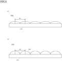
- the first screen 150 and the second screen 160 are, as illustrated in Fig. 2 (a) and Fig. 2 (b) , a transmission type screen provided with microlens arrays 152 and 162.
- Each microlens array 152 and 162 is obtained by arranging convex lenses in a matrix form.
- a display image is displayed on the other surface side thereof.
- the display light L2 is incident on one side surface of the second screen 160 from the display 120
- the display image is displayed on the other surface side thereof.
- the display light N1 corresponding to the display image emitted from the abovementioned other surface side of the first screen 150 is emitted toward the plane mirror 170.
- the display light N2 corresponding to the display image emitted from the abovementioned other surface side of the second screen 160 is also emitted toward the plane mirror 170.
- An arrangement pitch P1 of the microlens array 152 of the first screen 150 is smaller than an arrangement pitch P2 of the microlens array 162 of the second screen 160.
- a diffusion angle D2 of the display light N2 becomes larger than a diffusion angle D1 of the display light N1.
- a light distribution angle ⁇ y of the second screen 160 is set to be larger than a light distribution angle ⁇ x of the first screen 150.
- the HUD device 1000 shown in Fig. 3 is such that a screen with a same light distribution angle is applied as the first screen 150 and the second screen 160. That is, when the imaging angle of the incident light to the first screen 150 and the imaging angle of the incident light to the second screen 160 are equal, display light with a same diffusion angle is emitted from the first screen 150 and the second screen each 160, respectively.
- other configurations are same as that of the HUD device 100.
- the fold mirror 130 is not shown in Figs. 3 and 4 for ease of description.
- an imaging angle ⁇ 1 to the first screen 150 and an imaging angle ⁇ 2 to the second screen 160 are made to be different by the imaging position adjustment mirror 140 (in the present embodiment, the imaging angle ⁇ 1 > the imaging angle ⁇ 2).
- the first screen 150 emits the display light N1 corresponding to the display light L1 that has been incident at the diffusion angle D1.
- the second screen 160 emits the display light N2 corresponding to the display light L2 that has been incident at the diffusion angle D2.
- the imaging angle ⁇ 1 > the imaging angle ⁇ 2, and the first screen 150 and the second screen 160 are a same screen, and thus, the diffusion angle D1 > the diffusion angle D2.
- the diffusion angle D1 of the display light N1 and the diffusion angle D2 of the display light N2 are different, and thus irradiation ranges of the display light N1 and the display light N2 are different when irradiating to an eyebox B of the driver E.
- the imaging angle ⁇ 1 and the imaging angle ⁇ 2 are that the imaging angle ⁇ 1 > the imaging angle ⁇ 2 as is the case with HUD device 1000
- the light distribution angle ⁇ y of the second screen 160 is larger than the light distribution angle ⁇ x of the first screen 150, and thus the diffusion angle D2 approaches the diffusion angle D1.
- the diffusion angle D2 becomes equal to the diffusion angle D1.
- the light distribution angle ⁇ x of the first screen 150 and the light distribution angle ⁇ y of the second screen 160 are set in such a manner that the first display light L1 and the second display light L2 uniformly irradiate the eyebox B of the driver E.
- the irradiation ranges of the display light N1 and the display light N2 are approximately equal when irradiating to the eyebox B of the driver E. Consequently, as described above in the background art, the display quality of the HUD device 100 can be enhanced.
- the arrangement pitch P1 of the microlens array 152 and the arrangement pitch P2 of the microlens array 162 are different from each other in accordance with a difference between the imaging angle ⁇ 1 of the display light L1 and the imaging angle ⁇ 2 of the display light L2, whereby the light distribution angle ⁇ x of the first screen 150 and the light distribution angle ⁇ y of the second screen 160 are adjusted.
- the diffusion angle D1 of the display light N1 and the diffusion angle D2 of the display light N2 become equal. Therefore, the display quality of the HUD device 100 can be enhanced.
- HUD device 100 has been described by an example in which two screens (first screen 150, second screen 160) are provided, but the embodiment is not limited to this and may be provided with three or more of screens.
- the HUD device 100 has been described by an example in which the arrangement pitch P1 of the microlens array 152 of the first screen 150 and the arrangement pitch P2 of the microlens array 162 of the second screen 160 are different from each other with a view to adjusting the light distribution angle ⁇ x of the first screen 150 and the light distribution angle ⁇ y of the second screen 160
- the embodiment is not limited thereto, and for example, may be configured in such a manner that curvature radiuses of the microlens array 152 and the microlens array 162 differ from each other.
- a light distribution angle becomes larger, as shown in Fig.
- the curvature radius of the microlens array 162 is made to be smaller than the microlens array 152 while the arrangement pitch P (PI, P2) each microlens array 152, 162 remains the same, and thus the diffusion angle D2 approaches the diffusion angle D1.
- the light distribution angles ⁇ x, ⁇ y may be adjusted by varying both the arrangement pitch P (P1, P2) and the curvature radius.
- the imaging position adjustment mirror 140 of the present invention is not limited to a case of configuring with the reflective imaging position adjustment mirror 140 described above, and can be configured with a refractive imaging position adjustment lens (not shown).
- This imaging position adjustment lens may be configured to adjust an imaging distance by, for example, respectively disposing two lenses having same refractive power at positions the distances to the display 120 from which are different, on an optical path of the display light L1 and the display light L2.
- this imaging position adjustment lens may be configured to adjust the imaging distance by respectively disposing two lenses having different refractive power on the optical path of the display light L1 and the display light L2.
- transmission type screens such as a holographic diffuser and a diffusion plate may be applied to the first screen 150 and the second screen 160 of the present invention. Even in a case of these translucent type screens, light distribution angles of the screens can be adjusted by adjusting a structure, a material, a composition, a manufacturing method, a combination of members and the like.
- the present invention can be applied to a display device for displaying an image, a head-up display device for displaying a virtual image, and the like.
Landscapes
- Physics & Mathematics (AREA)
- General Physics & Mathematics (AREA)
- Optics & Photonics (AREA)
- Engineering & Computer Science (AREA)
- Chemical & Material Sciences (AREA)
- Combustion & Propulsion (AREA)
- Transportation (AREA)
- Mechanical Engineering (AREA)
- Computer Hardware Design (AREA)
- Theoretical Computer Science (AREA)
- Instrument Panels (AREA)
Claims (2)
- Dispositif d'affichage (100) comprenant :un affichage unique (120) configuré pour émettre une lumière d'affichage (L, L1, L2, N1, N2) ;une unité de réglage de position d'imagerie (140) configurée pour recevoir la lumière d'affichage, générer des première et seconde lumières d'affichage (L1, L2), et régler une distance de l'unité de réglage de position d'imagerie (140) en soi à une position d'imagerie dans la seconde lumière d'affichage de manière à être plus longue qu'une distance de l'unité de réglage de position d'imagerie (140) en soi à la position d'imagerie dans la première lumière d'affichage ;un premier écran (150) configuré pour être disposé à la position d'imagerie dans la première lumière d'affichage, le premier écran (150) comprenant un réseau de microlentilles (152) ; etun second écran (160) configuré pour être disposé à la position d'imagerie dans la seconde lumière d'affichage, le second écran (160) comprenant un réseau de microlentilles (162),caractérisé en ce que :un pas du réseau de microlentilles (152) du premier écran (150) est inférieur à un pas du réseau de microlentilles (162) du second écran (160) et/ou le rayon de courbure du réseau de microlentilles (162) du second écran (160) est inférieur au rayon de courbure du réseau de microlentilles (152) du premier écran (150), de manière à ce qu'un angle de distribution de lumière (θy) du second écran (160) soit réglé pour être plus grand qu'un angle de distribution de lumière (θx) du premier écran (150).
- Dispositif d'affichage selon la revendication 1, comprenant en outre :un système optique configuré pour guider les première et seconde lumières d'affichage (N1, N2) depuis les premier et second écrans (150, 160) vers un élément projeté, irradiant ainsi les première et seconde lumières d'affichage réfléchies vers l'élément projeté vers le globe oculaire (B) d'un spectateur (E),où les angles de distribution de la lumière des premier et second écrans (150, 160) sont réglés de manière à ce que les première et seconde lumières d'affichage irradient uniformément le globe oculaire.
Applications Claiming Priority (2)
| Application Number | Priority Date | Filing Date | Title |
|---|---|---|---|
| JP2016088371 | 2016-04-26 | ||
| PCT/JP2017/015133 WO2017188008A1 (fr) | 2016-04-26 | 2017-04-13 | Dispositif d'affichage |
Publications (3)
| Publication Number | Publication Date |
|---|---|
| EP3451045A1 EP3451045A1 (fr) | 2019-03-06 |
| EP3451045A4 EP3451045A4 (fr) | 2019-11-27 |
| EP3451045B1 true EP3451045B1 (fr) | 2021-05-26 |
Family
ID=60161571
Family Applications (1)
| Application Number | Title | Priority Date | Filing Date |
|---|---|---|---|
| EP17789295.7A Active EP3451045B1 (fr) | 2016-04-26 | 2017-04-13 | Dispositif d'affichage |
Country Status (4)
| Country | Link |
|---|---|
| US (1) | US10488657B2 (fr) |
| EP (1) | EP3451045B1 (fr) |
| JP (1) | JP6879299B2 (fr) |
| WO (1) | WO2017188008A1 (fr) |
Families Citing this family (5)
| Publication number | Priority date | Publication date | Assignee | Title |
|---|---|---|---|---|
| JP2019164239A (ja) * | 2018-03-19 | 2019-09-26 | 株式会社リコー | 表示装置及び機器 |
| TWI676823B (zh) * | 2018-12-26 | 2019-11-11 | 中強光電股份有限公司 | 抬頭顯示裝置 |
| JP7565526B2 (ja) * | 2020-05-21 | 2024-10-11 | パナソニックIpマネジメント株式会社 | ヘッドアップディスプレイシステム |
| JP7279728B2 (ja) * | 2021-03-22 | 2023-05-23 | カシオ計算機株式会社 | 投影装置及び投影方法 |
| US11994678B2 (en) * | 2021-10-08 | 2024-05-28 | Coretronic Corporation | Image generation unit comprising a reflecting mirror disposed between a first and a second illumination system and head-up display |
Family Cites Families (8)
| Publication number | Priority date | Publication date | Assignee | Title |
|---|---|---|---|---|
| JPH03227736A (ja) | 1990-01-31 | 1991-10-08 | Yazaki Corp | 表示装置 |
| JP2010164941A (ja) * | 2008-10-30 | 2010-07-29 | Honda Motor Co Ltd | 車両用表示装置 |
| JP6031741B2 (ja) | 2011-10-06 | 2016-11-24 | 日本精機株式会社 | 表示装置 |
| US9030749B2 (en) * | 2012-08-01 | 2015-05-12 | Microvision, Inc. | Bifocal head-up display system |
| JP6149543B2 (ja) * | 2013-06-28 | 2017-06-21 | アイシン・エィ・ダブリュ株式会社 | ヘッドアップディスプレイ装置 |
| JP2015034919A (ja) * | 2013-08-09 | 2015-02-19 | 株式会社デンソー | 情報表示装置 |
| JP5930231B2 (ja) * | 2014-08-20 | 2016-06-08 | 日本精機株式会社 | 投影装置及びヘッドアップディスプレイ装置 |
| JP2016053680A (ja) | 2014-09-04 | 2016-04-14 | 株式会社Jvcケンウッド | 画像表示再生装置および射出瞳拡大方法 |
-
2017
- 2017-04-13 WO PCT/JP2017/015133 patent/WO2017188008A1/fr not_active Ceased
- 2017-04-13 US US16/093,925 patent/US10488657B2/en active Active
- 2017-04-13 EP EP17789295.7A patent/EP3451045B1/fr active Active
- 2017-04-13 JP JP2018514494A patent/JP6879299B2/ja active Active
Also Published As
| Publication number | Publication date |
|---|---|
| US10488657B2 (en) | 2019-11-26 |
| EP3451045A1 (fr) | 2019-03-06 |
| JP6879299B2 (ja) | 2021-06-02 |
| JPWO2017188008A1 (ja) | 2019-03-28 |
| WO2017188008A1 (fr) | 2017-11-02 |
| US20190107713A1 (en) | 2019-04-11 |
| EP3451045A4 (fr) | 2019-11-27 |
Similar Documents
| Publication | Publication Date | Title |
|---|---|---|
| EP3200006B1 (fr) | Dispositif d'affichage tête haute | |
| EP3185061B1 (fr) | Dispositif de projection et dispositif d'affichage tête haute | |
| EP3447561B1 (fr) | Dispositif d'affichage tête haute | |
| US9081179B2 (en) | Head-up display device | |
| EP3330769B1 (fr) | Dispositif d'affichage tête haute | |
| EP3451045B1 (fr) | Dispositif d'affichage | |
| EP3415973B1 (fr) | Dispositif d'affichage et affichage tête haute | |
| US20180188529A1 (en) | Screen device and head-up display device | |
| JP6738543B2 (ja) | 表示装置及びヘッドアップディスプレイ | |
| JP4914731B2 (ja) | 車両用表示ユニット | |
| JP6414131B2 (ja) | 投影装置及びヘッドアップディスプレイ装置 | |
| JP7112644B2 (ja) | ヘッドアップディスプレイ装置 | |
| JP7143264B2 (ja) | 車両用表示装置 | |
| JP2017097115A (ja) | スクリーン装置及びヘッドアップディスプレイ装置 | |
| JP2017227681A (ja) | ヘッドアップディスプレイ装置 | |
| WO2016136060A1 (fr) | Système optique de projection, et dispositif de projection d'image comportant ce système | |
| CN216927274U (zh) | 平视显示器 | |
| JP2022170871A (ja) | ヘッドアップディスプレイ |
Legal Events
| Date | Code | Title | Description |
|---|---|---|---|
| STAA | Information on the status of an ep patent application or granted ep patent |
Free format text: STATUS: THE INTERNATIONAL PUBLICATION HAS BEEN MADE |
|
| PUAI | Public reference made under article 153(3) epc to a published international application that has entered the european phase |
Free format text: ORIGINAL CODE: 0009012 |
|
| STAA | Information on the status of an ep patent application or granted ep patent |
Free format text: STATUS: REQUEST FOR EXAMINATION WAS MADE |
|
| 17P | Request for examination filed |
Effective date: 20181107 |
|
| AK | Designated contracting states |
Kind code of ref document: A1 Designated state(s): AL AT BE BG CH CY CZ DE DK EE ES FI FR GB GR HR HU IE IS IT LI LT LU LV MC MK MT NL NO PL PT RO RS SE SI SK SM TR |
|
| AX | Request for extension of the european patent |
Extension state: BA ME |
|
| DAV | Request for validation of the european patent (deleted) | ||
| DAX | Request for extension of the european patent (deleted) | ||
| A4 | Supplementary search report drawn up and despatched |
Effective date: 20191025 |
|
| RIC1 | Information provided on ipc code assigned before grant |
Ipc: G02B 27/01 20060101AFI20191021BHEP Ipc: B60K 35/00 20060101ALI20191021BHEP |
|
| GRAP | Despatch of communication of intention to grant a patent |
Free format text: ORIGINAL CODE: EPIDOSNIGR1 |
|
| STAA | Information on the status of an ep patent application or granted ep patent |
Free format text: STATUS: GRANT OF PATENT IS INTENDED |
|
| INTG | Intention to grant announced |
Effective date: 20210222 |
|
| GRAS | Grant fee paid |
Free format text: ORIGINAL CODE: EPIDOSNIGR3 |
|
| GRAA | (expected) grant |
Free format text: ORIGINAL CODE: 0009210 |
|
| STAA | Information on the status of an ep patent application or granted ep patent |
Free format text: STATUS: THE PATENT HAS BEEN GRANTED |
|
| AK | Designated contracting states |
Kind code of ref document: B1 Designated state(s): AL AT BE BG CH CY CZ DE DK EE ES FI FR GB GR HR HU IE IS IT LI LT LU LV MC MK MT NL NO PL PT RO RS SE SI SK SM TR |
|
| REG | Reference to a national code |
Ref country code: GB Ref legal event code: FG4D |
|
| REG | Reference to a national code |
Ref country code: CH Ref legal event code: EP |
|
| REG | Reference to a national code |
Ref country code: DE Ref legal event code: R096 Ref document number: 602017039347 Country of ref document: DE |
|
| REG | Reference to a national code |
Ref country code: AT Ref legal event code: REF Ref document number: 1396805 Country of ref document: AT Kind code of ref document: T Effective date: 20210615 |
|
| REG | Reference to a national code |
Ref country code: IE Ref legal event code: FG4D |
|
| REG | Reference to a national code |
Ref country code: LT Ref legal event code: MG9D |
|
| REG | Reference to a national code |
Ref country code: AT Ref legal event code: MK05 Ref document number: 1396805 Country of ref document: AT Kind code of ref document: T Effective date: 20210526 |
|
| PG25 | Lapsed in a contracting state [announced via postgrant information from national office to epo] |
Ref country code: LT Free format text: LAPSE BECAUSE OF FAILURE TO SUBMIT A TRANSLATION OF THE DESCRIPTION OR TO PAY THE FEE WITHIN THE PRESCRIBED TIME-LIMIT Effective date: 20210526 Ref country code: FI Free format text: LAPSE BECAUSE OF FAILURE TO SUBMIT A TRANSLATION OF THE DESCRIPTION OR TO PAY THE FEE WITHIN THE PRESCRIBED TIME-LIMIT Effective date: 20210526 Ref country code: HR Free format text: LAPSE BECAUSE OF FAILURE TO SUBMIT A TRANSLATION OF THE DESCRIPTION OR TO PAY THE FEE WITHIN THE PRESCRIBED TIME-LIMIT Effective date: 20210526 Ref country code: AT Free format text: LAPSE BECAUSE OF FAILURE TO SUBMIT A TRANSLATION OF THE DESCRIPTION OR TO PAY THE FEE WITHIN THE PRESCRIBED TIME-LIMIT Effective date: 20210526 Ref country code: BG Free format text: LAPSE BECAUSE OF FAILURE TO SUBMIT A TRANSLATION OF THE DESCRIPTION OR TO PAY THE FEE WITHIN THE PRESCRIBED TIME-LIMIT Effective date: 20210826 |
|
| REG | Reference to a national code |
Ref country code: NL Ref legal event code: MP Effective date: 20210526 |
|
| PG25 | Lapsed in a contracting state [announced via postgrant information from national office to epo] |
Ref country code: GR Free format text: LAPSE BECAUSE OF FAILURE TO SUBMIT A TRANSLATION OF THE DESCRIPTION OR TO PAY THE FEE WITHIN THE PRESCRIBED TIME-LIMIT Effective date: 20210827 Ref country code: IS Free format text: LAPSE BECAUSE OF FAILURE TO SUBMIT A TRANSLATION OF THE DESCRIPTION OR TO PAY THE FEE WITHIN THE PRESCRIBED TIME-LIMIT Effective date: 20210926 Ref country code: SE Free format text: LAPSE BECAUSE OF FAILURE TO SUBMIT A TRANSLATION OF THE DESCRIPTION OR TO PAY THE FEE WITHIN THE PRESCRIBED TIME-LIMIT Effective date: 20210526 Ref country code: RS Free format text: LAPSE BECAUSE OF FAILURE TO SUBMIT A TRANSLATION OF THE DESCRIPTION OR TO PAY THE FEE WITHIN THE PRESCRIBED TIME-LIMIT Effective date: 20210526 Ref country code: PL Free format text: LAPSE BECAUSE OF FAILURE TO SUBMIT A TRANSLATION OF THE DESCRIPTION OR TO PAY THE FEE WITHIN THE PRESCRIBED TIME-LIMIT Effective date: 20210526 Ref country code: NO Free format text: LAPSE BECAUSE OF FAILURE TO SUBMIT A TRANSLATION OF THE DESCRIPTION OR TO PAY THE FEE WITHIN THE PRESCRIBED TIME-LIMIT Effective date: 20210826 Ref country code: LV Free format text: LAPSE BECAUSE OF FAILURE TO SUBMIT A TRANSLATION OF THE DESCRIPTION OR TO PAY THE FEE WITHIN THE PRESCRIBED TIME-LIMIT Effective date: 20210526 Ref country code: PT Free format text: LAPSE BECAUSE OF FAILURE TO SUBMIT A TRANSLATION OF THE DESCRIPTION OR TO PAY THE FEE WITHIN THE PRESCRIBED TIME-LIMIT Effective date: 20210927 |
|
| PG25 | Lapsed in a contracting state [announced via postgrant information from national office to epo] |
Ref country code: NL Free format text: LAPSE BECAUSE OF FAILURE TO SUBMIT A TRANSLATION OF THE DESCRIPTION OR TO PAY THE FEE WITHIN THE PRESCRIBED TIME-LIMIT Effective date: 20210526 |
|
| PG25 | Lapsed in a contracting state [announced via postgrant information from national office to epo] |
Ref country code: RO Free format text: LAPSE BECAUSE OF FAILURE TO SUBMIT A TRANSLATION OF THE DESCRIPTION OR TO PAY THE FEE WITHIN THE PRESCRIBED TIME-LIMIT Effective date: 20210526 Ref country code: ES Free format text: LAPSE BECAUSE OF FAILURE TO SUBMIT A TRANSLATION OF THE DESCRIPTION OR TO PAY THE FEE WITHIN THE PRESCRIBED TIME-LIMIT Effective date: 20210526 Ref country code: EE Free format text: LAPSE BECAUSE OF FAILURE TO SUBMIT A TRANSLATION OF THE DESCRIPTION OR TO PAY THE FEE WITHIN THE PRESCRIBED TIME-LIMIT Effective date: 20210526 Ref country code: DK Free format text: LAPSE BECAUSE OF FAILURE TO SUBMIT A TRANSLATION OF THE DESCRIPTION OR TO PAY THE FEE WITHIN THE PRESCRIBED TIME-LIMIT Effective date: 20210526 Ref country code: CZ Free format text: LAPSE BECAUSE OF FAILURE TO SUBMIT A TRANSLATION OF THE DESCRIPTION OR TO PAY THE FEE WITHIN THE PRESCRIBED TIME-LIMIT Effective date: 20210526 Ref country code: SK Free format text: LAPSE BECAUSE OF FAILURE TO SUBMIT A TRANSLATION OF THE DESCRIPTION OR TO PAY THE FEE WITHIN THE PRESCRIBED TIME-LIMIT Effective date: 20210526 Ref country code: SM Free format text: LAPSE BECAUSE OF FAILURE TO SUBMIT A TRANSLATION OF THE DESCRIPTION OR TO PAY THE FEE WITHIN THE PRESCRIBED TIME-LIMIT Effective date: 20210526 |
|
| REG | Reference to a national code |
Ref country code: DE Ref legal event code: R097 Ref document number: 602017039347 Country of ref document: DE |
|
| PLBE | No opposition filed within time limit |
Free format text: ORIGINAL CODE: 0009261 |
|
| STAA | Information on the status of an ep patent application or granted ep patent |
Free format text: STATUS: NO OPPOSITION FILED WITHIN TIME LIMIT |
|
| 26N | No opposition filed |
Effective date: 20220301 |
|
| PG25 | Lapsed in a contracting state [announced via postgrant information from national office to epo] |
Ref country code: IS Free format text: LAPSE BECAUSE OF FAILURE TO SUBMIT A TRANSLATION OF THE DESCRIPTION OR TO PAY THE FEE WITHIN THE PRESCRIBED TIME-LIMIT Effective date: 20210926 Ref country code: AL Free format text: LAPSE BECAUSE OF FAILURE TO SUBMIT A TRANSLATION OF THE DESCRIPTION OR TO PAY THE FEE WITHIN THE PRESCRIBED TIME-LIMIT Effective date: 20210526 |
|
| PG25 | Lapsed in a contracting state [announced via postgrant information from national office to epo] |
Ref country code: IT Free format text: LAPSE BECAUSE OF FAILURE TO SUBMIT A TRANSLATION OF THE DESCRIPTION OR TO PAY THE FEE WITHIN THE PRESCRIBED TIME-LIMIT Effective date: 20210526 |
|
| REG | Reference to a national code |
Ref country code: CH Ref legal event code: PL |
|
| GBPC | Gb: european patent ceased through non-payment of renewal fee |
Effective date: 20220413 |
|
| REG | Reference to a national code |
Ref country code: BE Ref legal event code: MM Effective date: 20220430 |
|
| PG25 | Lapsed in a contracting state [announced via postgrant information from national office to epo] |
Ref country code: MC Free format text: LAPSE BECAUSE OF FAILURE TO SUBMIT A TRANSLATION OF THE DESCRIPTION OR TO PAY THE FEE WITHIN THE PRESCRIBED TIME-LIMIT Effective date: 20210526 Ref country code: LU Free format text: LAPSE BECAUSE OF NON-PAYMENT OF DUE FEES Effective date: 20220413 Ref country code: LI Free format text: LAPSE BECAUSE OF NON-PAYMENT OF DUE FEES Effective date: 20220430 Ref country code: GB Free format text: LAPSE BECAUSE OF NON-PAYMENT OF DUE FEES Effective date: 20220413 Ref country code: FR Free format text: LAPSE BECAUSE OF NON-PAYMENT OF DUE FEES Effective date: 20220430 Ref country code: CH Free format text: LAPSE BECAUSE OF NON-PAYMENT OF DUE FEES Effective date: 20220430 |
|
| PG25 | Lapsed in a contracting state [announced via postgrant information from national office to epo] |
Ref country code: BE Free format text: LAPSE BECAUSE OF NON-PAYMENT OF DUE FEES Effective date: 20220430 |
|
| PG25 | Lapsed in a contracting state [announced via postgrant information from national office to epo] |
Ref country code: IE Free format text: LAPSE BECAUSE OF NON-PAYMENT OF DUE FEES Effective date: 20220413 |
|
| PG25 | Lapsed in a contracting state [announced via postgrant information from national office to epo] |
Ref country code: HU Free format text: LAPSE BECAUSE OF FAILURE TO SUBMIT A TRANSLATION OF THE DESCRIPTION OR TO PAY THE FEE WITHIN THE PRESCRIBED TIME-LIMIT; INVALID AB INITIO Effective date: 20170413 |
|
| PG25 | Lapsed in a contracting state [announced via postgrant information from national office to epo] |
Ref country code: MK Free format text: LAPSE BECAUSE OF FAILURE TO SUBMIT A TRANSLATION OF THE DESCRIPTION OR TO PAY THE FEE WITHIN THE PRESCRIBED TIME-LIMIT Effective date: 20210526 Ref country code: CY Free format text: LAPSE BECAUSE OF FAILURE TO SUBMIT A TRANSLATION OF THE DESCRIPTION OR TO PAY THE FEE WITHIN THE PRESCRIBED TIME-LIMIT Effective date: 20210526 |
|
| PG25 | Lapsed in a contracting state [announced via postgrant information from national office to epo] |
Ref country code: MT Free format text: LAPSE BECAUSE OF FAILURE TO SUBMIT A TRANSLATION OF THE DESCRIPTION OR TO PAY THE FEE WITHIN THE PRESCRIBED TIME-LIMIT Effective date: 20210526 |
|
| PGFP | Annual fee paid to national office [announced via postgrant information from national office to epo] |
Ref country code: DE Payment date: 20250305 Year of fee payment: 9 |
|
| PG25 | Lapsed in a contracting state [announced via postgrant information from national office to epo] |
Ref country code: TR Free format text: LAPSE BECAUSE OF FAILURE TO SUBMIT A TRANSLATION OF THE DESCRIPTION OR TO PAY THE FEE WITHIN THE PRESCRIBED TIME-LIMIT Effective date: 20210526 |