EP3451360A1 - Movable contact operating mechanism of leakage circuit breaker - Google Patents
Movable contact operating mechanism of leakage circuit breaker Download PDFInfo
- Publication number
- EP3451360A1 EP3451360A1 EP17788586.0A EP17788586A EP3451360A1 EP 3451360 A1 EP3451360 A1 EP 3451360A1 EP 17788586 A EP17788586 A EP 17788586A EP 3451360 A1 EP3451360 A1 EP 3451360A1
- Authority
- EP
- European Patent Office
- Prior art keywords
- movable contact
- buckle
- circuit breaker
- hole
- leakage circuit
- Prior art date
- Legal status (The legal status is an assumption and is not a legal conclusion. Google has not performed a legal analysis and makes no representation as to the accuracy of the status listed.)
- Withdrawn
Links
- 230000007246 mechanism Effects 0.000 title claims abstract description 19
- 230000009471 action Effects 0.000 claims description 9
- 230000000149 penetrating effect Effects 0.000 claims description 4
- 238000005516 engineering process Methods 0.000 abstract 1
- 238000000034 method Methods 0.000 description 3
- 230000008569 process Effects 0.000 description 3
- 230000000694 effects Effects 0.000 description 2
- 230000007547 defect Effects 0.000 description 1
- 238000012986 modification Methods 0.000 description 1
- 230000004048 modification Effects 0.000 description 1
Images






Classifications
-
- H—ELECTRICITY
- H01—ELECTRIC ELEMENTS
- H01H—ELECTRIC SWITCHES; RELAYS; SELECTORS; EMERGENCY PROTECTIVE DEVICES
- H01H71/00—Details of the protective switches or relays covered by groups H01H73/00 - H01H83/00
- H01H71/10—Operating or release mechanisms
- H01H71/12—Automatic release mechanisms with or without manual release
- H01H71/24—Electromagnetic mechanisms
- H01H71/2463—Electromagnetic mechanisms with plunger type armatures
-
- H—ELECTRICITY
- H01—ELECTRIC ELEMENTS
- H01H—ELECTRIC SWITCHES; RELAYS; SELECTORS; EMERGENCY PROTECTIVE DEVICES
- H01H71/00—Details of the protective switches or relays covered by groups H01H73/00 - H01H83/00
- H01H71/10—Operating or release mechanisms
- H01H71/12—Automatic release mechanisms with or without manual release
-
- H—ELECTRICITY
- H01—ELECTRIC ELEMENTS
- H01H—ELECTRIC SWITCHES; RELAYS; SELECTORS; EMERGENCY PROTECTIVE DEVICES
- H01H71/00—Details of the protective switches or relays covered by groups H01H73/00 - H01H83/00
- H01H71/10—Operating or release mechanisms
- H01H71/50—Manual reset mechanisms which may be also used for manual release
- H01H71/52—Manual reset mechanisms which may be also used for manual release actuated by lever
- H01H71/526—Manual reset mechanisms which may be also used for manual release actuated by lever the lever forming a toggle linkage with a second lever, the free end of which is directly and releasably engageable with a contact structure
-
- H—ELECTRICITY
- H01—ELECTRIC ELEMENTS
- H01H—ELECTRIC SWITCHES; RELAYS; SELECTORS; EMERGENCY PROTECTIVE DEVICES
- H01H71/00—Details of the protective switches or relays covered by groups H01H73/00 - H01H83/00
- H01H71/10—Operating or release mechanisms
- H01H71/50—Manual reset mechanisms which may be also used for manual release
- H01H71/54—Manual reset mechanisms which may be also used for manual release actuated by tumbler
-
- H—ELECTRICITY
- H01—ELECTRIC ELEMENTS
- H01H—ELECTRIC SWITCHES; RELAYS; SELECTORS; EMERGENCY PROTECTIVE DEVICES
- H01H83/00—Protective switches, e.g. circuit-breaking switches, or protective relays operated by abnormal electrical conditions otherwise than solely by excess current
- H01H83/20—Protective switches, e.g. circuit-breaking switches, or protective relays operated by abnormal electrical conditions otherwise than solely by excess current operated by excess current as well as by some other abnormal electrical condition
- H01H83/22—Protective switches, e.g. circuit-breaking switches, or protective relays operated by abnormal electrical conditions otherwise than solely by excess current operated by excess current as well as by some other abnormal electrical condition the other condition being imbalance of two or more currents or voltages
-
- H—ELECTRICITY
- H01—ELECTRIC ELEMENTS
- H01H—ELECTRIC SWITCHES; RELAYS; SELECTORS; EMERGENCY PROTECTIVE DEVICES
- H01H71/00—Details of the protective switches or relays covered by groups H01H73/00 - H01H83/00
- H01H71/10—Operating or release mechanisms
- H01H71/12—Automatic release mechanisms with or without manual release
- H01H71/40—Combined electrothermal and electromagnetic mechanisms
-
- H—ELECTRICITY
- H01—ELECTRIC ELEMENTS
- H01H—ELECTRIC SWITCHES; RELAYS; SELECTORS; EMERGENCY PROTECTIVE DEVICES
- H01H83/00—Protective switches, e.g. circuit-breaking switches, or protective relays operated by abnormal electrical conditions otherwise than solely by excess current
- H01H83/20—Protective switches, e.g. circuit-breaking switches, or protective relays operated by abnormal electrical conditions otherwise than solely by excess current operated by excess current as well as by some other abnormal electrical condition
- H01H83/22—Protective switches, e.g. circuit-breaking switches, or protective relays operated by abnormal electrical conditions otherwise than solely by excess current operated by excess current as well as by some other abnormal electrical condition the other condition being imbalance of two or more currents or voltages
- H01H83/223—Protective switches, e.g. circuit-breaking switches, or protective relays operated by abnormal electrical conditions otherwise than solely by excess current operated by excess current as well as by some other abnormal electrical condition the other condition being imbalance of two or more currents or voltages with bimetal elements
-
- H—ELECTRICITY
- H01—ELECTRIC ELEMENTS
- H01H—ELECTRIC SWITCHES; RELAYS; SELECTORS; EMERGENCY PROTECTIVE DEVICES
- H01H83/00—Protective switches, e.g. circuit-breaking switches, or protective relays operated by abnormal electrical conditions otherwise than solely by excess current
- H01H83/20—Protective switches, e.g. circuit-breaking switches, or protective relays operated by abnormal electrical conditions otherwise than solely by excess current operated by excess current as well as by some other abnormal electrical condition
- H01H83/22—Protective switches, e.g. circuit-breaking switches, or protective relays operated by abnormal electrical conditions otherwise than solely by excess current operated by excess current as well as by some other abnormal electrical condition the other condition being imbalance of two or more currents or voltages
- H01H83/226—Protective switches, e.g. circuit-breaking switches, or protective relays operated by abnormal electrical conditions otherwise than solely by excess current operated by excess current as well as by some other abnormal electrical condition the other condition being imbalance of two or more currents or voltages with differential transformer
Definitions
- Leakage circuit breakers are widely used in industrial, commercial, residential and other places, mainly for short-circuit overload protection and leakage protection.
- the existing 1P+N products generally use widened product width, that is, assembling the leakage module on the basis of the existing miniature leakage circuit breaker; or under the circumstances that the basic structure of the existing miniature circuit breaker is unchanged, the circuit board, the releasing mechanism and the leakage current test device are added on the upper or lower side of the miniature circuit breaker, and the product width is generally large. Or by lengthening the length of the product, that is, the circuit board and the test device releasing mechanism is provided on the upper or lower side of the miniature circuit breaker. Therefore, the length of the leakage circuit breaker must be increased.
Landscapes
- Physics & Mathematics (AREA)
- Electromagnetism (AREA)
- Breakers (AREA)
Abstract
Description
- The invention relates to a low-voltage leakage circuit breaker, and in particular, to a movable contact operating mechanism of leakage circuit breaker.
- Leakage circuit breakers are widely used in industrial, commercial, residential and other places, mainly for short-circuit overload protection and leakage protection. The existing 1P+N products generally use widened product width, that is, assembling the leakage module on the basis of the existing miniature leakage circuit breaker; or under the circumstances that the basic structure of the existing miniature circuit breaker is unchanged, the circuit board, the releasing mechanism and the leakage current test device are added on the upper or lower side of the miniature circuit breaker, and the product width is generally large. Or by lengthening the length of the product, that is, the circuit board and the test device releasing mechanism is provided on the upper or lower side of the miniature circuit breaker. Therefore, the length of the leakage circuit breaker must be increased. Now the number of electrical equipment used by users increases, and the number of power distribution circuits increases, therefore, the width of the power distribution box must be increased or lengthened. However, the design space of the power distribution box in the house is generally not easy to be changed, so the existing wider or longer leakage circuit breaker cannot meet the needs of users. There is an urgent need for a leakage circuit breaker of small size and high breaking capacity to fill the domestic gap.
- However, the existing leakage circuit breakers are complicated due to the movable contact operating mechanism, and the realization of the above functions requires a plurality of components to be completed together. The volume of the mechanism is relatively large, and it is difficult to realize miniaturization.
- The invention overcomes the defect of the large volume in the existing leakage circuit breaker, and provides a novel movable contact operating mechanism of leakage circuit breaker which can make the length or width of the leakage circuit breaker smaller than the prior art products and can better meet the needs of customers.
- To achieve the objective above, the invention adopts the technical solution as follows: a movable contact operating mechanism of leakage circuit breaker, comprising a movable contact, a bounce buckle, a movable contact support, a locking spring, a locking buckle and a tension spring, wherein the movable contact is fixedly arranged on the movable contact support, a long through hole is provided on the movable contact support, a pin shaft is provided in the long through hole, two ends of the pin shaft are arranged on a base and a cover of the leakage circuit breaker; one end of the tension spring is connected to the movable contact support, and the connection point with the movable contact support is located above the long through hole; the other end of the tension spring is fixedly connected to the base of the leakage circuit breaker or other components fixedly connected to the base; the bounce buckle is hinged on an upper end of the movable contact support; the bounce buckle is connected to the handle of the leakage circuit breaker through a first linkage; a central part of the locking buckle movably sheathes the pin shaft by means of a provided through hole, a contact pin is provided extendingly above the locking buckle, and the contact pin is abutedly engagable with the bounce buckle to limit the rotation of the bounce buckle; a driving pin and a resetting pin are provided below the locking buckle, wherein the driving pin is correspondingly arranged with the release putter of the leakage circuit breaker, the putter pushes the driving pin to rotate to realize the rotation of the locking buckle, and the locking buckle rotates to unlock the contact between the bounce buckle and the contact pin, then the movable contact support causes the leakage circuit breaker to open under the action of the tension spring; a spring base is provided at the upper end of the resetting pin; one end of the locking spring abuts against the spring base, the other end thereof abuts against the base of the leakage circuit breaker or other components fixedly connected to the base; the locking spring causes the driving pin to rotate towards the side of the release putter of the leakage circuit breaker.
- By adopting the above scheme, the miniaturization of the moving contact operating mechanism of the leakage circuit breaker is realized, which is embodied in that: the rotation of the movable contact is realized by the engagement of the movable contact support and the tension spring, and the process of movement of the movable contact is: when the fixed contact is closed, the contact pin of the locking buckle is abutedly engagable with the bounce buckle to limit the rotation of the bounce buckle; when a situation action of the leakage circuit breaker occurs, the release putter of the leakage circuit breaker pushes the driving pin to rotate to realize the rotation of the locking buckle, and the locking buckle rotates to unlock the contact between the bounce buckle and the contact pin, then the movable contact support causes the leakage circuit breaker to open under the action of the tension spring; at the same time, the handle is also rotated to the open state. When the fixed contact is closed, the handle is rotated. At this time, the first linkage drives the bounce buckle and the movable contact support to rotate around the pin shaft until the movable contact comes into contact with the fixed contact, and then the handle continues to rotate. At this time, since the movable contact has already came into contact with the fixed contact, and the position will not be changed, so the movable contact support can only move as a whole, which drives the pin shaft to come into contact with the left side of the long through hole, so that the contact between the movable contact and the fixed contact is much closer, and a good contact between them is ensured.
- Further, a cavity is provided on the side of the base below the movable contact support, the upper end of the movable contact is inserted into the cavity to realize the fixed connection with the movable contact support; the long through hole of the movable contact support is located in the cavity portion, a long through hole of the movable contact corresponding to the long through hole of the movable contact support is provided at the upper end of the movable contact, and the pin shaft is provided through the long through hole and the long through hole of the movable contact; a connection hole is provided at the upper end of the resetting pin and is connected with a second linkage, and a bimetal is abutedly provided on the other end of the second linkage.
- By adopting the above solution, the structure of the product is more reasonable. The connection between the movable contact and the movable contact support is convenient, and the long through hole and the long through hole of the movable contact form the connection through hole of the pin shaft, which drives both the movable contact and the movable contact support to receive the force of the pin shaft, and the movement is relatively stable.
- Further, a locking nose is provided on the bounce buckle, a contact shoulder step abutedly engagable with the locking nose of the bounce buckle is provided on the contact pin; a connection through hole for the connection of the first linkage is provided on the bounce buckle, and an arc-shaped groove is provided above the movable contact support and corresponding to the connection through hole of the bounce buckle; after the first linkage is connected to the bounce buckle, the penetrating end thereof is disposed in the arc-shaped groove and can slip therein.
- By adopting the above solution, the abutted engagement between the bounce buckle and the contact pin is relatively stable. In addition, after the first linkage is connected to the bounce buckle, the penetrating end thereof is disposed in the arc-shaped groove and can slip therein. Accordingly, the rotation of the bounce buckle and the movable contact support is limited, which makes the engagement of the two more reasonable. Alternatively, the arc-shaped groove may not be provided and the first linkage is not set to be penetrated, and the two are limitedly engageble with each other only by the length of the first linkage.
- Finally, a long hole for the tension spring to be placed is provided above the long through hole on the movable contact support; an arc-shaped convex rib is provided adjacent to the side of the movable contact on the driving pin of the locking buckle; when the locking buckle is pushed to rotate by the release putter of the leakage circuit breaker, the top of the convex rib of the driving pin abuts against the movable contact.
- By adopting the above solution, the long hole is provided to facilitate the connection of the tension spring. In addition, when the locking buckle is pushed to rotate by the release putter of the leakage circuit breaker, the convex rib of the driving pin abuts against the movable contact. Accordingly, on disengagement, the top of the convex rib comes into contact with the movable contact, and the temperature of the movable contact is relatively high, so the top of the convex rib comes into line contact with the moving contact, the contact area is small, and the damage of the locking buckle is small.
- The invention will be further described with reference to the drawings.
-
-
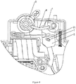
FIG. 1 is the stereoscopic view illustrating the closed state in the embodiment of the invention; -
FIG. 2 is the stereoscopic view illustrating the open state in the embodiment of the invention; -
FIG. 3 is the stereoscopic view illustrating the closing process in the embodiment of the invention; -
FIG. 4 is the stereoscopic view illustrating the relationship between the movable contact support and the tension spring at the critical points of closing in the embodiment of the invention; -
FIG. 5 is the stereoscopic view illustrating the movable contact support in the embodiment of the invention; -
FIG. 6 is the schematic view illustrating the rear structure inFIG. 5 ; -
FIG. 7 is the stereoscopic view illustrating the locking buckle in the embodiment of the invention; -
FIG. 8 is the schematic view illustrating the rear structure inFIG. 7 ; -
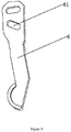
FIG. 9 is the schematic view illustrating the structure of the movable contact; -
FIG. 10 is the view illustrating the using status in the embodiment of the invention; -
FIG. 11 is the stereoscopic view illustrating the bounce buckle in the embodiment of the invention. - As shown in the figures, a movable contact operating mechanism of leakage circuit breaker, comprising a
movable contact 6, a bounce buckle 1, amovable contact support 2, alocking spring 3, alocking buckle 4 and atension spring 5; themovable contact 6 is fixedly arranged on themovable contact support 2, a long throughhole 21 is provided on themovable contact support 2, apin shaft 7 is provided in the long throughhole 21, two ends of thepin shaft 7 are arranged on a base and a cover of the leakage circuit breaker; here, thepin shaft 7 is arranged on the base or the cover, which may be an indirect or a direct arrangement, which mainly means that thepin shaft 7 is fixed relative to the base and the cover. The manner in which thepin 7 is attached to the base and the cover is also common in the prior art. One end of thetension spring 5 is connected to themovable contact support 2, and the connection point with themovable contact support 2 is located above the long throughhole 21, wherein the upper side refers to the side close to thefirst linkage 8; accordingly, themovable contact support 2 rotates around thepin shaft 7 under the pulling of thetension spring 5, and themovable contact 6 below thepin shaft 7 can realize the disconnection motion with the fixed contact. The other end of thetension spring 5 is fixedly connected to the base of the leakage circuit breaker or other components fixedly connected to the base; the bounce buckle 1 is hinged on an upper end of themovable contact support 2; the bounce buckle 1 is connected to thehandle 9 of the leakage circuit breaker through afirst linkage 8. The function of thefirst linkage 8 is also found in a conventional circuit breaker, so the function and motion mode of thefirst linkage 8 are not further described here. A central part of thelocking buckle 4 movably sheathes thepin shaft 7 by means of a provided throughhole 41, acontact pin 42 is provided extendingly above thelocking buckle 4, and thecontact pin 42 is abutedly engagable with the bounce buckle 1 to limit the rotation of the bounce buckle 1; thecontact pin 42 realizes the abutted locking or the unlocked engagement on the bounce buckle 1; when the bounce buckle is locked abutedly, the upper end of themovable contact support 2 is fixed, and thetension spring 5 cannot pull themovable contact 6. A drivingpin 43 and a resettingpin 44 are provided below thelocking buckle 5, wherein the drivingpin 43 is correspondingly arranged with therelease putter 10 of the leakage circuit breaker, theputter 10 pushes the drivingpin 43 to rotate to realize the rotation of thelocking buckle 4, and thelocking buckle 4 rotates to unlock the contact between the bounce buckle 1 and thecontact pin 43, then themovable contact support 2 causes the leakage circuit breaker to open under the action of thetension spring 5. Aspring base 441 is provided at the upper end of the resettingpin 44; one end of thelocking spring 3 abuts against thespring base 441, the other end thereof abuts against the base of the leakage circuit breaker or other components fixedly connected to the base; thelocking spring 3 causes the drivingpin 44 to rotate towards the side of therelease putter 10 of the leakage circuit breaker. By adopting the above scheme, the miniaturization of the moving contact operating mechanism of the leakage circuit breaker is realized, which is embodied in that: the rotation of themovable contact 6 is realized by the engagement of thelocking buckle 4, bounce buckle 1,movable contact support 2 andtension spring 5, and the swing of the movable contact is realized by such simple components, which is very convenient. The specific process of movement of themovable contact 6 is: when the fixed contact is closed, thecontact pin 42 of thelocking buckle 4 is abutedly engagable with the bounce buckle 1 to limit the rotation of the bounce buckle; when a situation action of the leakage circuit breaker occurs, therelease putter 10 of the leakage circuit breaker pushes the drivingpin 43 to rotate to realize the rotation of thelocking buckle 4, and thelocking buckle 4 rotates to unlock the contact between the bounce buckle 1 and thecontact pin 42, then themovable contact support 2 causes the leakage circuit breaker to open under the action of thetension spring 5; at the same time, thehandle 9 is also rotated to the open state. The closing action: when thehandle 9 rotates clockwise under the action of an external force, thefirst linkage 8 is driven to the right; thefirst linkage 8 pushes the bounce buckle 1 to be abutedly engagable with the pin shaft correspondingly to right side of the long throughhole 21 of themovable contact support 2; when thehandle 9 continues to be rotated clockwise, thelocking buckle 4 continues to rotate clockwise around thepin shaft 7; meanwhile, themovable contact support 2 and themovable contact 6 rotate clockwise around the contact point of themovable contact 6 and the fixes contact, under the push of the bounce buckle 1 and the pulling of thetension spring 5. At this time, the right side of the long throughhole 21 of themovable contact support 2 is separated from the pin shaft to generate the super stroke. When thehandle 9 cannot continues to be pushed, the leakage circuit breaker product closes. Accordingly, the contact between themovable contact 6 and the fixed contact is much closer, and a good contact between themovable contact 6 and the fixed contact is ensured. - In the embodiment of the invention, a
cavity 22 is provided on the side of the base below themovable contact support 2, the upper end of themovable contact 6 is inserted into thecavity 22 to realize the fixed connection with themovable contact support 2; accordingly, the connection between themovable contact 6 and themovable contact support 2 is convenient. The long throughhole 21 of themovable contact support 2 is located in thecavity 22 portion, a long throughhole 61 of the movable contact corresponding to the long throughhole 21 of themovable contact support 2 is provided at the upper end of themovable contact 6, and thepin shaft 7 is provided through the long throughhole 21 and the long throughhole 61 of the movable contact, which drives both themovable contact 6 and themovable contact support 2 to receive the force of thepin shaft 7, and the movement is relatively stable. Aconnection hole 442 is provided at the upper end of the resettingpin 44 of thelocking buckle 4 and is connected with asecond linkage 4421, and abimetal 4422 is abutedly provided on the other end of thesecond linkage 4421; accordingly, thebimetal 4422 can control the movement of thelocking buckle 4 to realize the overload protection. - In the embodiment of the invention, a
locking nose 11 is provided on the bounce buckle 1, acontact shoulder step 421 abutedly engagable with thelocking nose 11 of the bounce buckle is provided on thecontact pin 42 of thelocking buckle 4; here, the engagement of thelocking nose 11 orcontact shoulder step 421 can also be implemented in other ways, such as the abutted engagement with the beveled surface, etc., the purpose of which is to facilitate the abutted engagement between the two, and to fix the upper end of the movable contact support when needed. A connection throughhole 12 for the connection of thefirst linkage 8 is provided on the bounce buckle 1, and an arc-shapedgroove 23 is provided above themovable contact support 2 and corresponding to the connection throughhole 12 of the bounce buckle; after thefirst linkage 8 is connected to the bounce buckle 1, the penetrating end thereof is disposed in the arc-shapedgroove 23 and can slip therein. Accordingly, the rotation of the bounce buckle 1 and themovable contact support 2 is limited, which makes the engagement of the two more reasonable. Alternatively, the arc-shapedgroove 23 may not be provided and thefirst linkage 8 is not set to be penetrated, and the two are limitedly engageble with each other only by the length of thefirst linkage 8. - In the embodiment of the invention, a long through 24 for the tension spring to be placed is provided above the long through
hole 21 on themovable contact support 2, which is convenient for the connection of thetension spring 5; an arc-shapedconvex rib 431 is provided adjacent to the side of themovable contact 6 on the drivingpin 43 of the lockingbuckle 4; when the lockingbuckle 4 is pushed to rotate by therelease putter 10 of the leakage circuit breaker, the top of theconvex rib 431 of the drivingpin 43 abuts against themovable contact 6. At this time, the temperature of the movable contact is relatively high, so the top of theconvex rib 431 comes into line contact with the movingcontact 6, the contact area is small, and the damage of the lockingbuckle 4 is small. - What has been disclosed in the invention is merely one of the preferred embodiments. Any partial changes or modifications originated from the technical idea of the invention that are easily deduced by those skilled in the art shall all fall within the protection scope of the invention.
Invention embodiment
Embodiments of the invention
Industrial applicability
Sequence table free content
Claims (5)
- A movable contact operating mechanism of leakage circuit breaker, comprising a movable contact, a bounce buckle, a movable contact support, a locking spring, a locking buckle and a tension spring, wherein the movable contact is fixedly arranged on the movable contact support, a long through hole is provided on the movable contact support, a pin shaft is provided in the long through hole, two ends of the pin shaft are arranged on a base and a cover of the leakage circuit breaker; one end of the tension spring is connected to the movable contact support, and the connection point with the movable contact support is located above the long through hole; the other end of the tension spring is fixedly connected to the base of the leakage circuit breaker or other components fixedly connected to the base; the bounce buckle is hinged on an upper end of the movable contact support; the bounce buckle is connected to the handle of the leakage circuit breaker through a first linkage; a central part of the locking buckle movably sheathes the pin shaft by means of a provided through hole, a contact pin is provided extendingly above the locking buckle, and the contact pin is abutedly engagable with the bounce buckle to limit the rotation of the bounce buckle; a driving pin and a resetting pin are provided below the locking buckle, wherein the driving pin is correspondingly arranged with the release putter of the leakage circuit breaker, the putter pushes the driving pin to rotate to realize the rotation of the locking buckle, and the locking buckle rotates to unlock the contact between the bounce buckle and the contact pin, then the movable contact support causes the leakage circuit breaker to open under the action of the tension spring; one end of the locking spring abuts against the spring base, the other end thereof abuts against the base of the leakage circuit breaker or other components fixedly connected to the base; the locking spring causes the driving pin to rotate towards the side of the release putter of the leakage circuit breaker.
- The movable contact operating mechanism of leakage circuit breaker according to claim 1, wherein a cavity is provided on the side of the base below the movable contact support, the upper end of the movable contact is inserted into the cavity to realize the fixed connection with the movable contact support; the long through hole of the movable contact support is located in the cavity portion, a long through hole of the movable contact corresponding to the long through hole of the movable contact support is provided at the upper end of the movable contact, and the pin shaft is provided through the long through hole and the long through hole of the movable contact; a connection hole is provided at the upper end of the resetting pin, the connection hole is connected with a second linkage, and a bimetal is abutedly provided on the other end of the second linkage.
- The movable contact operating mechanism of leakage circuit breaker according to claim 1 or claim 2, wherein a locking nose is provided on the bounce buckle, a contact shoulder step abutedly engagable with the locking nose of the bounce buckle is provided on the contact pin; a connection through hole for the connection of the first linkage is provided on the bounce buckle, and an arc-shaped groove is provided above the movable contact support and corresponding to the connection through hole of the bounce buckle; after the first linkage is connected to the bounce buckle, the penetrating end thereof is disposed in the arc-shaped groove and can slip therein.
- The movable contact operating mechanism of leakage circuit breaker according to claim 1 or claim 2, wherein a long hole for the tension spring to be placed is provided above the long through hole on the movable contact support; an arc-shaped convex rib is provided adjacent to the side of the movable contact on the driving pin of the locking buckle; when the locking buckle is pushed to rotate by the release putter of the leakage circuit breaker, the top of the convex rib of the driving pin abuts against the movable contact.
- The movable contact operating mechanism of leakage circuit breaker according to claim 3, wherein a long hole for the tension spring to be placed is provided above the long through hole on the movable contact support; an arc-shaped convex rib is provided adjacent to the side of the movable contact on the driving pin of the locking buckle; when the locking buckle is pushed to rotate by the release putter of the leakage circuit breaker, the top of the convex rib of the driving pin abuts against the movable contact.
Applications Claiming Priority (2)
| Application Number | Priority Date | Filing Date | Title |
|---|---|---|---|
| CN201610271823.7A CN105762033B (en) | 2016-04-27 | 2016-04-27 | A kind of moving contact operating mechanism of leakage circuit breakers |
| PCT/CN2017/078222 WO2017185933A1 (en) | 2016-04-27 | 2017-03-25 | Movable contact operating mechanism of leakage circuit breaker |
Publications (2)
| Publication Number | Publication Date |
|---|---|
| EP3451360A1 true EP3451360A1 (en) | 2019-03-06 |
| EP3451360A4 EP3451360A4 (en) | 2019-12-04 |
Family
ID=56326109
Family Applications (1)
| Application Number | Title | Priority Date | Filing Date |
|---|---|---|---|
| EP17788586.0A Withdrawn EP3451360A4 (en) | 2016-04-27 | 2017-03-25 | Movable contact operating mechanism of leakage circuit breaker |
Country Status (5)
| Country | Link |
|---|---|
| EP (1) | EP3451360A4 (en) |
| CN (1) | CN105762033B (en) |
| AU (1) | AU2017255390A1 (en) |
| WO (1) | WO2017185933A1 (en) |
| ZA (1) | ZA201807500B (en) |
Cited By (1)
| Publication number | Priority date | Publication date | Assignee | Title |
|---|---|---|---|---|
| EP4064317A1 (en) | 2021-03-26 | 2022-09-28 | Schneider Electric Industries SAS | Electrical protection device and electrical switchboard comprising such a protection device |
Families Citing this family (14)
| Publication number | Priority date | Publication date | Assignee | Title |
|---|---|---|---|---|
| CN105762033B (en) * | 2016-04-27 | 2018-09-07 | 乐清市也为电气有限公司 | A kind of moving contact operating mechanism of leakage circuit breakers |
| CN106229233A (en) * | 2016-08-26 | 2016-12-14 | 加西亚电子电器股份有限公司 | A kind of miniature circuit breaker |
| CN106783426B (en) * | 2017-01-13 | 2018-08-07 | 乐清市也为电气有限公司 | A kind of electric switch |
| CN106783423B (en) * | 2017-01-13 | 2018-08-07 | 乐清市也为电气有限公司 | A kind of operating mechanism of electric switch |
| CN106847629B (en) * | 2017-04-11 | 2018-07-20 | 厦门大恒科技有限公司 | Miniature circuit breaker and circuit protection device |
| CN108054061B (en) * | 2018-01-18 | 2023-11-24 | 温州奥来电器有限公司 | Leakage mechanism of leakage circuit breaker |
| CN108155067B (en) * | 2018-02-02 | 2024-01-26 | 温州奥来电器有限公司 | Electric leakage circuit breaker with disconnectable live wire and zero line |
| CN109119299B (en) * | 2018-09-19 | 2023-10-20 | 余姚市嘉荣电子电器有限公司 | Leakage protector |
| CN111785573B (en) * | 2020-07-07 | 2025-02-11 | 浙江正泰电器股份有限公司 | Load Break Switch |
| CN111834163B (en) * | 2020-07-10 | 2025-03-25 | 厦门宏发开关设备有限公司 | Single-pole or multi-pole circuit breakers |
| CN112530752B (en) * | 2020-12-25 | 2025-01-24 | 浙江奥来电器有限公司 | A leakage circuit breaker |
| CN115036186A (en) * | 2021-03-05 | 2022-09-09 | 上海电器科学研究所(集团)有限公司 | Locking mechanism for circuit breaker |
| CN113871264B (en) * | 2021-09-30 | 2024-07-30 | 环宇高科有限公司 | Small-size automatic opening and closing circuit breaker |
| CN115424902B (en) * | 2022-09-07 | 2024-04-23 | 加西亚电子电器股份有限公司 | A leakage circuit breaker |
Family Cites Families (10)
| Publication number | Priority date | Publication date | Assignee | Title |
|---|---|---|---|---|
| DE29723582U1 (en) * | 1997-09-30 | 1998-10-15 | Siemens AG, 80333 München | Circuit breaker |
| FR2779568B1 (en) * | 1998-06-04 | 2000-07-13 | Schneider Electric Ind Sa | ELECTRICAL CUT-OFF DEVICE INCLUDING A DIFFERENTIAL TRIP DEVICE AND CIRCUIT BREAKER INCLUDING SUCH A DEVICE |
| CN2752948Y (en) * | 2004-08-25 | 2006-01-18 | 陈志贤 | Small type circuit breaker operating mechanism |
| CN201498453U (en) * | 2009-08-28 | 2010-06-02 | 温州光源电器有限公司 | Rightward operated miniature circuit breaker |
| CN102655066A (en) * | 2012-03-31 | 2012-09-05 | 温州奥来电器有限公司 | High-breaking-capacity energy-storage-type biaxial miniature circuit breaker |
| CN103489724A (en) * | 2013-09-16 | 2014-01-01 | 乐清市胜宇电气有限公司 | Residual-current circuit breaker |
| CN103700548A (en) * | 2013-12-30 | 2014-04-02 | 温州奥来电器有限公司 | Inserted energy-storing high-breaking small breaker |
| CN103745892B (en) * | 2014-01-16 | 2016-01-20 | 创奇科技有限公司 | The operating mechanism of miniature circuit breaker |
| CN105762033B (en) * | 2016-04-27 | 2018-09-07 | 乐清市也为电气有限公司 | A kind of moving contact operating mechanism of leakage circuit breakers |
| CN205564679U (en) * | 2016-04-27 | 2016-09-07 | 乐清市也为电气有限公司 | Moving contact operating device of electric leakage circuit breaker |
-
2016
- 2016-04-27 CN CN201610271823.7A patent/CN105762033B/en active Active
-
2017
- 2017-03-25 WO PCT/CN2017/078222 patent/WO2017185933A1/en not_active Ceased
- 2017-03-25 AU AU2017255390A patent/AU2017255390A1/en not_active Abandoned
- 2017-03-25 EP EP17788586.0A patent/EP3451360A4/en not_active Withdrawn
-
2018
- 2018-11-08 ZA ZA2018/07500A patent/ZA201807500B/en unknown
Cited By (2)
| Publication number | Priority date | Publication date | Assignee | Title |
|---|---|---|---|---|
| EP4064317A1 (en) | 2021-03-26 | 2022-09-28 | Schneider Electric Industries SAS | Electrical protection device and electrical switchboard comprising such a protection device |
| FR3121272A1 (en) * | 2021-03-26 | 2022-09-30 | Schneider Electric Industries Sas | Electrical protection device and electrical panel comprising such a protection device |
Also Published As
| Publication number | Publication date |
|---|---|
| ZA201807500B (en) | 2019-06-26 |
| EP3451360A4 (en) | 2019-12-04 |
| WO2017185933A1 (en) | 2017-11-02 |
| AU2017255390A1 (en) | 2018-11-22 |
| CN105762033B (en) | 2018-09-07 |
| CN105762033A (en) | 2016-07-13 |
Similar Documents
| Publication | Publication Date | Title |
|---|---|---|
| CN110265272B (en) | A small circuit breaker operating mechanism and a small circuit breaker | |
| CN113161211B (en) | Circuit breaker device | |
| WO2017185933A1 (en) | Movable contact operating mechanism of leakage circuit breaker | |
| CN111477512B (en) | Plug-in circuit breaker | |
| EP3171386A1 (en) | Low-voltage circuit breaker with residual current tripping device | |
| WO2017167086A1 (en) | Make/break mechanism for electrical switch | |
| WO2016074321A1 (en) | Breaker operation mechanism | |
| US9136076B2 (en) | Mechanically operated cell switch of vacuum circuit breaker | |
| US11239692B2 (en) | Automatic transfer switch utilizing back-to-back mounted molded case circuit breakers or molded case switches to connect a load to a normal power source and a standby power source | |
| CN203631449U (en) | Operating mechanism of miniature circuit breaker | |
| CN103646828A (en) | Operating mechanism of miniature circuit breaker and working process thereof | |
| CN110491748A (en) | Earth leakage circuit breaker | |
| CN102915857B (en) | Wall-mounted switch | |
| CN104299865A (en) | Switching-off and switching-on bi-stable-state spring retaining mechanism used for breaker | |
| CN210040100U (en) | Miniature circuit breaker operating device and miniature circuit breaker | |
| CN102332371B (en) | Small-sized circuit breaker | |
| CN103094012B (en) | Circuit-breaker | |
| CN112820592A (en) | Terminal blocks and plug-in circuit breakers | |
| CN204424190U (en) | A kind of miniature circuit breaker | |
| CN110828245B (en) | Connecting mechanism of plug-in circuit breaker | |
| CN104428863A (en) | Circuit interrupter and indicator apparatus | |
| CN111900025B (en) | Electric isolating switch fuse set | |
| CN108400038B (en) | Small-sized circuit breaker | |
| CN107452562B (en) | Residual current operated circuit breaker with leakage indication and overcurrent protection | |
| CN219716780U (en) | Operating mechanism and circuit breaker |
Legal Events
| Date | Code | Title | Description |
|---|---|---|---|
| STAA | Information on the status of an ep patent application or granted ep patent |
Free format text: STATUS: THE INTERNATIONAL PUBLICATION HAS BEEN MADE |
|
| PUAI | Public reference made under article 153(3) epc to a published international application that has entered the european phase |
Free format text: ORIGINAL CODE: 0009012 |
|
| STAA | Information on the status of an ep patent application or granted ep patent |
Free format text: STATUS: REQUEST FOR EXAMINATION WAS MADE |
|
| 17P | Request for examination filed |
Effective date: 20181126 |
|
| AK | Designated contracting states |
Kind code of ref document: A1 Designated state(s): AL AT BE BG CH CY CZ DE DK EE ES FI FR GB GR HR HU IE IS IT LI LT LU LV MC MK MT NL NO PL PT RO RS SE SI SK SM TR |
|
| AX | Request for extension of the european patent |
Extension state: BA ME |
|
| DAV | Request for validation of the european patent (deleted) | ||
| DAX | Request for extension of the european patent (deleted) | ||
| A4 | Supplementary search report drawn up and despatched |
Effective date: 20191106 |
|
| RIC1 | Information provided on ipc code assigned before grant |
Ipc: H01H 71/52 20060101ALI20191030BHEP Ipc: H01H 83/22 20060101ALI20191030BHEP Ipc: H01H 71/40 20060101ALN20191030BHEP Ipc: H01H 71/12 20060101AFI20191030BHEP Ipc: H01H 71/24 20060101ALI20191030BHEP |
|
| STAA | Information on the status of an ep patent application or granted ep patent |
Free format text: STATUS: THE APPLICATION IS DEEMED TO BE WITHDRAWN |
|
| 18D | Application deemed to be withdrawn |
Effective date: 20200609 |