EP3453296A1 - Installation einer sanitärwanne auf einem traggestell und verfahren zur montage - Google Patents
Installation einer sanitärwanne auf einem traggestell und verfahren zur montage Download PDFInfo
- Publication number
- EP3453296A1 EP3453296A1 EP18181562.2A EP18181562A EP3453296A1 EP 3453296 A1 EP3453296 A1 EP 3453296A1 EP 18181562 A EP18181562 A EP 18181562A EP 3453296 A1 EP3453296 A1 EP 3453296A1
- Authority
- EP
- European Patent Office
- Prior art keywords
- sealing strip
- support frame
- sanitary tub
- groove
- installation according
- Prior art date
- Legal status (The legal status is an assumption and is not a legal conclusion. Google has not performed a legal analysis and makes no representation as to the accuracy of the status listed.)
- Granted
Links
Images


Classifications
-
- A—HUMAN NECESSITIES
- A47—FURNITURE; DOMESTIC ARTICLES OR APPLIANCES; COFFEE MILLS; SPICE MILLS; SUCTION CLEANERS IN GENERAL
- A47K—SANITARY EQUIPMENT; ACCESSORIES THEREFOR, e.g. TOILET ACCESSORIES
- A47K3/00—Baths; Showers; Appurtenances therefor
- A47K3/008—Sealing between wall and bathtub or shower tray
-
- A—HUMAN NECESSITIES
- A47—FURNITURE; DOMESTIC ARTICLES OR APPLIANCES; COFFEE MILLS; SPICE MILLS; SUCTION CLEANERS IN GENERAL
- A47K—SANITARY EQUIPMENT; ACCESSORIES THEREFOR, e.g. TOILET ACCESSORIES
- A47K3/00—Baths; Showers; Appurtenances therefor
- A47K3/28—Showers or bathing douches
- A47K3/40—Pans or trays
- A47K3/405—Pans or trays flush with the surrounding floor, e.g. for easy access
Definitions
- the present invention relates to an installation of a sanitary tub on a support frame with a supporting frame formed from profiles, on which the sanitary tub is supported, wherein the profiles of the support frame at least partially a sealing strip is fixed, and a method for mounting a sanitary tub to a support frame.
- the DE 10 2013 113 765 A1 discloses a support frame for a sanitary tub, which is composed of a plurality of profile bars and connecting elements. As a result, a sanitary tub can be stably supported.
- On the support frame sealing strips are mounted on an upper side, where a sealing film is fixed.
- the sanitary tub is placed on the sealing strips, so that a seal between the underside of the sanitary tub and the sealing strips is made.
- the position of the seal is slightly inside the sanitary tub, which is disadvantageous in a possible water ingress, since the water can collect in the area of the edge of the sanitary tub.
- a sealing film is therefore placed around a flanged edge of the sanitary tub, which makes the assembly consuming.
- the inventive installation with a sanitary tub and a support frame simplifies the installation and sealing of a sanitary tub in that an edge of the sanitary tub is at least partially inserted into a groove on a sealing strip, which is at least partially fixed to the profiles of the support frame.
- the sealing strip can not only be used on an underside of the sanitary tub, but directly seals the edge of the sanitary tub by being inserted into the groove of the sealing strip becomes.
- a sealing foil no longer has to be guided around the edge of the sanitary tub, but can connect directly to the sealing strip.
- the edge of the sanitary tub is formed by a web projecting downwardly in the installation situation.
- the bar is thus vertically aligned, and the sanitary tub can be easily installed by inserting into the groove and disassembled if necessary.
- an upwardly open receiving groove for at least a portion of the sealing strip is formed on each profile.
- the sealing strip can thus be arranged frame-shaped circumferentially on the support frame, wherein when retracting the sealing strip in a one-piece seal must be made only at a single point a seal on a shock.
- the adjacent end faces of the sealing strip can be sealed by welding or corresponding sealant or by a certain contact pressure.
- the profiles are end connected to each other preferably via corner pieces, on each of which a curved groove is formed.
- the radius of curvature of the curved groove can be chosen so that the sealing strip this curvature can follow without problems for the tightness.
- the corner pieces can engage with at least one connecting portion in a groove of a profile to allow a stable construction of the support frame.
- the sealing strip is preferably formed in cross-section S or Z-shaped.
- another web is provided in the vertical direction, in particular a rollover, which engages over an outer groove wall of the profile.
- a sealing film may be fixed, which provides a building-side seal.
- Each profile of the support frame preferably has a support portion, which at least indirectly with the interposition of an elastic member Bottom of the sanitary tub is supported. The position of the support and the seal is thus positioned separately on the profile.
- an inwardly facing retaining strip may be formed for fixing a holder of a drain fitting. This allows the position of the drain fitting set more precisely during assembly.
- the support frame formed with profiles is first mounted, in order to then retract a circumferential sealing strip in the support frame.
- a circumferential sealing strip In a groove of the sealing strip then an edge of the sanitary tub is inserted and fixed there by clamping. A seal can thus be made directly on the bent edge of the sanitary tub.
- a sanitary tub 1 comprises a tub body 2, which has a drain opening 3 in a central region and has a peripheral edge 5, which is angled and has a vertical web and a horizontal section 4.
- the tub body 2 may also have other shapes.
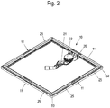
- FIG. 2 a support frame for the sanitary tub 1 is shown with a support frame 10 having four profiles 11 which are interconnected via corner pieces 50.
- the support frame 10 may be supported on a plurality of foot elements, which are adjustable in height for adjusting bumps.
- the profiles 11 have on their upper side on a support portion on which elastic support strips 25 are mounted, which can not extend over the entire length of the profiles 11, although this is optional of course possible.
- a holder 20 is fixed to which a drain fitting 21 is fixed.
- a cover 22 of the drain fitting protrudes beyond the drain opening 3 of the sanitary tub 1 in the installed situation.
- the profile 11 comprises a groove 12 with an outer groove wall 13 and an inner groove wall 15 into which a sealing strip 30 made of an elastic material, in particular of EPDM, is drawn.
- a projection 14 protrudes inwardly, and on the inner groove wall 15, a projection 16, wherein the projections 14 and 16 engage in corresponding receptacles on the sealing strip 30 and thus prevent them after insertion into the groove 12th is pulled out again.
- the profile 11 also has a support portion 17 on which the support bar 25 is fixed from elastic material. This engages with a fastening projection in an undercut groove on the support portion 17, wherein other mechanical geometries for fixing the support bar 25 can be provided.
- On the support bar is the horizontal portion 4 of the tub body 2.
- the profile 11 has on an inner side two webs 18 as fastening means for the holder 20, which can be snapped onto the webs 18.
- other profiles for fixing the holder 20 may be provided on the profile 11.
- the sealing strip 30 has on the outer groove wall on a connecting portion 35 and a vertical web 36 which surrounds the outer groove wall 13 in a U-shape.
- a sealing film 40 is glued to the outside at an edge portion 41 or fixed by other fastening means.
- the sealing of the sanitary tub 1 takes place directly on the edge 5, which is designed as a vertical web and engages in the groove 31 of the sealing strip 30.
- one or more inwardly projecting sealing lips 32 are formed on the sealing strip 30, which form individual sealing planes.
- the sealing lips 32 are arranged on an outer side of the edge 5, so that the water does not flow under a leak in the sanitary tub, but is collected directly outside on the edge 5.
- An end face of the edge 5 lies in the non-visible area within the groove 31, so that in a production of the sanitary tub 1 made of enamelled steel sheet any errors in the enamelling in this area are not visible.
- the sanitary tub 1 can of course be made of other materials instead of enameled steel sheet.
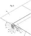
- a corner region of the support frame 10 is shown, in which two profiles 11 are connected to each other via a corner piece 50.
- the corner piece 50 has an upwardly open curved groove 51 which is aligned with the groove 12 of the profiles 11.
- a groove wall 52 thus aligned with the outer groove wall 13, wherein the curvature of the groove 51 is selected so that the edge 5 also extends in an arc and sealed in the groove 31 of the curved sealing strip 30 is arranged.
- both the sealing strip 30 and the edge 5 can be accommodated arcuately in the corner region in the groove 51.
- An inner corner piece 53 is formed substantially triangular in plan view and can also be arcuately curved as needed.
- the corner piece 50 is fixed via connecting portions 54 which engage in a downwardly open groove 19 on the profile 11.
- the connecting portions 54 may be fixed in the groove 19 by gluing, clamping or other fastening means.
- the profiles 11 are preferably made of metal, and the corner pieces 50 may also be made of metal or alternatively of plastic.
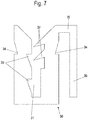
- the sealing strip 30 is shown in cross section.
- two sealing lips 32 are arranged on one side, which are clamped against the edge 5 can be applied.
- recesses 33 are formed in the groove wall, which increase the elasticity of the groove wall.
- recesses 34 are provided on the outer side, into which the projections 14 and 16 of the profile 11 engage, to prevent withdrawal of the sealing strip 30 upwards.
- the sealing strip 30 of the connecting portion 35 and the vertical web 36 can be seen to engage around the outer groove wall 13 in a U-shape.
- the sealing strip 30 is thus formed in cross-section Z or S-shaped.
- the sealing film 40 can be connected in the corner with corner pieces to allow a circumferential seal.
- the sealing film 40 may also be formed of an elastic material which is stretchable in the corner region in order to be able to compensate for the curvature of the sealing strip 30.
- the sealing strip 30 can be mounted on the groove 12. Subsequently, then the edge 5 of the sanitary tub 1 is inserted into the sealing strip 30, wherein the sanitary tub 1 is fixed only by clamping, so that a disassembly is easy to carry out.
- the support frame with the seal can also be delivered pre-assembled to the construction site. The support frame is then set, sealed with foil, before then the sanitary tub 1 is used.
Landscapes
- Health & Medical Sciences (AREA)
- Public Health (AREA)
- Epidemiology (AREA)
- General Health & Medical Sciences (AREA)
- Specific Sealing Or Ventilating Devices For Doors And Windows (AREA)
Abstract
Description
- Die vorliegende Erfindung betrifft eine Installation einer Sanitärwanne auf einem Traggestell mit einem aus Profilen gebildeten Tragrahmen, auf dem die Sanitärwanne abgestützt ist, wobei an den Profilen des Tragrahmens zumindest bereichsweise eine Dichtleiste fixiert ist, und ein Verfahren zur Montage einer Sanitärwanne an einem Traggestell.
- Die
DE 10 2013 113 765 A1 offenbart ein Traggestell für eine Sanitärwanne, das aus mehreren Profilstangen und Verbindungselementen zusammengesetzt ist. Dadurch kann eine Sanitärwanne stabil abgestützt werden. An dem Traggestell werden an einer Oberseite Dichtleisten montiert, an denen eine Dichtungsfolie festgelegt ist. Die Sanitärwanne wird auf die Dichtleisten aufgelegt, so dass eine Abdichtung zwischen der Unterseite der Sanitärwanne und den Dichtleisten hergestellt wird. Dies vereinfacht zwar die Montage, allerdings ist die Position der Abdichtung etwas innenliegend unterhalb der Sanitärwanne, was bei einem möglichen Wassereintritt nachteilig ist, da sich das Wasser im Bereich des Randes der Sanitärwanne sammeln kann. Eine Dichtfolie wird daher um einen umgebördelten Rand der Sanitärwanne gelegt, was die Montage aufwändig gestaltet. - Es ist daher Aufgabe der vorliegenden Erfindung, eine Installation einer Sanitärwanne zu schaffen, die eine leichte Montage ermöglicht und die Abdichtung der Sanitärwanne verbessert.
- Diese Aufgabe wird mit einer Installation einer Sanitärwanne auf einem Traggestell mit den Merkmalen des Anspruches 1 sowie einem Verfahren mit den Merkmalen des Anspruches 12 gelöst.
- Die erfindungsgemäße Installation mit einer Sanitärwanne und einem Traggestell vereinfacht die Montage und Abdichtung einer Sanitärwanne dadurch, dass ein Rand der Sanitärwanne zumindest teilweise in eine Nut an einer Dichtleiste eingesteckt ist, die zumindest bereichsweise an den Profilen des Tragrahmens fixiert ist. Dadurch kann die Dichtleiste nicht nur an einer Unterseite der Sanitärwanne verwendet werden, sondern dichtet unmittelbar den Rand der Sanitärwanne ab, indem dieser in die Nut der Dichtleiste eingesteckt wird. Dadurch muss eine Dichtungsfolie nicht mehr um den Rand der Sanitärwanne herum geführt werden, sondern kann unmittelbar an der Dichtleiste anschließen.
- Vorzugsweise ist der Rand der Sanitärwanne durch einen in der Einbausituation nach unten ragenden Steg gebildet. Der Steg ist somit vertikal ausgerichtet, und die Sanitärwanne kann durch Einstecken in die Nut einfach montiert und bei Bedarf auch wieder demontiert werden.
- Vorzugsweise ist an jedem Profil eine nach oben offene Aufnahmenut für zumindest einen Teil der Dichtleiste ausgebildet. Die Dichtleiste kann damit rahmenförmig umlaufend an dem Tragrahmen angeordnet werden, wobei beim Einziehen der Dichtleiste bei einer einstückigen Dichtung nur an einer einzigen Stelle eine Abdichtung an einem Stoß erfolgen muss. Die aneinander anliegenden Stirnflächen der Dichtleiste können durch Verschweißung oder entsprechende Dichtmittel oder durch einen gewissen Anpressdruck abgedichtet werden.
- Für eine zuverlässige Abdichtung kann in die Nut der Dichtleiste mindestens eine Dichtlippe oder ein Dichtvorsprung hervorstehen. Dadurch wird an einer oder mehreren Dichtlippen oder Dichtvorsprüngen eine definierte Abdichtung zwischen dem Rand und der Dichtleiste erreicht.
- Um eine umlaufende Anordnung der Dichtleiste ohne Knicke zu ermöglichen, sind die Profile endseitig vorzugsweise über Eckstücke miteinander verbunden, an denen jeweils eine kurvenförmige Nut ausgebildet ist. Der Krümmungsradius der kurvenförmigen Nut kann dabei so gewählt werden, dass die Dichtleiste dieser Krümmung ohne Probleme für die Dichtigkeit folgen kann. Die Eckstücke können dabei mit zumindest einem Verbindungsabschnitt in eine Nut eines Profils eingreifen, um eine stabile Konstruktion des Tragrahmens zu ermöglichen.
- Die Dichtleiste ist vorzugsweise im Querschnitt S- oder Z-förmig ausgebildet. Zusätzlich zu der Nut ist somit ein weiterer Steg in vertikaler Richtung vorgesehen, insbesondere ein Überschlag, der eine äußere Nutwand des Profils übergreift. An diesem Überschlag oder weiteren Steg kann eine Dichtfolie fixiert sein, die eine bauwerksseitige Abdichtung bereitstellt.
- Jedes Profil des Tragrahmens weist vorzugsweise einen Stützabschnitt auf, der zumindest mittelbar unter Zwischenschaltung eines elastischen Bauteils eine Unterseite der Sanitärwanne abstützt. Die Position der Abstützung und der Dichtung ist somit getrennt an dem Profil positioniert. An zumindest einem Profil des Tragrahmens, vorzugsweise aber an allen Profilen, kann eine zur Innenseite gewandte Halteleiste zur Fixierung eines Halters einer Ablaufarmatur ausgebildet sein. Dadurch lässt sich die Position der Ablaufarmatur exakter bei der Montage einstellen.
- Bei dem erfindungsgemäßen Verfahren wird zunächst der mit Profilen gebildete Tragrahmen montiert, um dann eine umlaufende Dichtleiste in den Tragrahmen einzuziehen. In eine Nut der Dichtleiste wird dann ein Rand der Sanitärwanne eingesteckt und dort klemmend fixiert. Eine Abdichtung kann somit unmittelbar an dem umgebogenen Rand der Sanitärwanne erfolgen.
- Die Erfindung wird nachfolgend anhand eines Ausführungsbeispiels mit Bezug auf die beigefügten Zeichnungen näher erläutert. Es zeigen:
- Figur 1
- eine perspektivische Ansicht einer Sanitärwanne;
- Figur 2
- eine perspektivische Ansicht eines Traggestells ohne Sanitärwanne;
- Figur 3
- eine perspektivische Schnittdarstellung einer erfindungsgemäßen Installation;
- Figur 4
- eine seitliche Schnittansicht der Installation der
Figur 3 ; - Figur 5
- eine Draufsicht auf einen Eckbereich eines erfindungsgemäßen Traggestells;
- Figur 6
- eine perspektivische Ansicht des Eckbereichs der
Figur 5 , und - Figur 7
- eine Querschnittsansicht einer Dichtleiste für die Installation.
- Eine Sanitärwanne 1 umfasst einen Wannenkörper 2, der in einem mittleren Bereich eine Ablauföffnung 3 aufweist und einen umlaufenden Rand 5 aufweist, der abgewinkelt ausgebildet ist und einen vertikalen Steg sowie einen horizontalen Abschnitt 4 aufweist. Der Wannenkörper 2 kann auch andere Formen aufweisen.
- In
Figur 2 ist ein Traggestell für die Sanitärwanne 1 mit einem Tragrahmen 10 gezeigt, der vier Profile 11 aufweist, die über Eckstücke 50 miteinander verbunden sind. Der Tragrahmen 10 kann auf mehreren Fußelementen abgestützt sein, die zur Anpassung von Bodenunebenheiten höhenverstellbar sind. - Die Profile 11 weisen an ihrer Oberseite einen Stützabschnitt auf, an dem elastische Auflageleisten 25 montiert sind, die sich nicht über die gesamte Länge der Profile 11 erstrecken können, auch wenn dies optional natürlich möglich ist. Auf diesen elastischen Auflageleisten 25 kann der horizontale Abschnitt 4 der Sanitärwanne 1 aufgelegt werden. Ferner ist erkennbar, dass an einem Profil 11 auf der nach innen gewandten Seite ein Halter 20 festgelegt ist, an dem eine Ablaufarmatur 21 fixiert ist. Ein Deckel 22 der Ablaufgarnitur ragt über die Ablauföffnung 3 der Sanitärwanne 1 in der eingebauten Situation hervor.
- In den
Figuren 3 und4 ist die Installation mit der Sanitärwanne 1 in einer eingebauten Position dargestellt. Das Profil 11 umfasst eine Nut 12 mit einer äußeren Nutwand 13 und einer inneren Nutwand 15, in die eine Dichtleiste 30 aus einem elastischen Material, insbesondere aus EPDM, eingezogen ist. An der äußeren Nutwand 13 steht ein Vorsprung 14 nach innen hervor, und an der inneren Nutwand 15 ein Vorsprung 16, wobei die Vorsprünge 14 und 16 in entsprechende Aufnahmen an der Dichtleiste 30 eingreifen und somit verhindern, dass diese nach dem Einfügen in die Nut 12 wieder herausgezogen wird. - Das Profil 11 weist ferner einen Auflageabschnitt 17 auf, an dem die Auflageleiste 25 aus elastischem Material fixiert ist. Diese greift mit einem Befestigungsvorsprung in eine hinterschnittene Nut an dem Auflageabschnitt 17 ein, wobei auch andere mechanische Geometrien zum Fixieren der Auflageleiste 25 vorgesehen werden können. Auf der Auflageleiste liegt der horizontale Abschnitt 4 des Wannenkörpers 2 auf.
- Ferner weist das Profil 11 an einer Innenseite zwei Stege 18 als Befestigungsmittel für den Halter 20 auf, der an den Stegen 18 eingerastet werden kann. Auch hier können an dem Profil 11 auch andere Profilierungen zur Fixierung des Halters 20 vorgesehen werden.
- Die Dichtleiste 30 weist an der äußeren Nutwand einen Verbindungsabschnitt 35 und einen vertikalen Steg 36 auf, der die äußere Nutwand 13 U-förmig umgibt. An dem Steg 36 ist an der Außenseite eine Dichtfolie 40 an einem Randabschnitt 41 angeklebt oder über andere Befestigungsmittel fixiert.
- Die Abdichtung der Sanitärwanne 1 erfolgt unmittelbar an dem Rand 5, der als vertikaler Steg ausgebildet ist und in die Nut 31 der Dichtleiste 30 eingreift. Hierfür sind an der Dichtleiste 30 ein oder mehrere nach innen ragende Dichtlippen 32 ausgebildet, die einzelne Dichtebenen ausbilden. Die Dichtlippen 32 sind dabei an einer Außenseite des Randes 5 angeordnet, so dass das Wasser bei einer Leckage nicht unter die Sanitärwanne strömt, sondern unmittelbar aussen an dem Rand 5 gesammelt wird. Eine Stirnseite des Randes 5 liegt dabei im nicht sichtbaren Bereich innerhalb der Nut 31, so dass bei einer Herstellung der Sanitärwanne 1 aus einem emaillierten Stahlblech etwaige Fehler bei der Emaillierung in diesem Bereich nicht sichtbar sind. Die Sanitärwanne 1 kann statt aus emailliertem Stahlblech natürlich auch aus andere Materialien hergestellt sein.
- In den
Figuren 5 und6 ist ein Eckbereich des Tragrahmens 10 gezeigt, bei dem zwei Profile 11 über ein Eckstück 50 miteinander verbunden sind. Das Eckstück 50 weist eine nach oben offene gebogene Nut 51 auf, die mit der Nut 12 der Profile 11 fluchtet. Eine Nutwand 52 fluchtet somit mit der äußeren Nutwand 13, wobei die Krümmung der Nut 51 so gewählt ist, dass der Rand 5 ebenfalls in einem Bogen verläuft und abgedichtet in der Nut 31 der gebogenen Dichtleiste 30 angeordnet bleibt. Insofern kann sowohl die Dichtleiste 30 als auch der Rand 5 bogenförmig in dem Eckbereich in der Nut 51 aufgenommen sein. Ein inneres Eckstück 53 ist in Draufsicht im Wesentlichen dreieckförmig ausgebildet und kann, je nach Bedarf, ebenfalls bogenförmig gekrümmt sein. - Wie in
Figur 6 gezeigt ist, wird das Eckstück 50 über Verbindungsabschnitte 54 fixiert, die in eine nach unten offene Nut 19 an dem Profil 11 eingreifen. Die Verbindungsabschnitte 54 können in der Nut 19 durch Kleben, Klemmen oder andere Befestigungsmittel fixiert sein. - Die Profile 11 bestehen vorzugsweise aus Metall, und die Eckstücke 50 können ebenfalls aus Metall oder alternativ aus Kunststoff hergestellt sein.
- In
Figur 7 ist die Dichtleiste 30 im Querschnitt gezeigt. In der Nut 31 sind auf einer Seite zwei Dichtlippen 32 angeordnet, die klemmend gegen den Rand 5 anlegbar sind. Auf der gegenüberliegenden Seite sind in der Nutwand Aussparungen 33 ausgebildet, die die Elastizität der Nutwand erhöhen. An dem U-förmigen Abschnitt der Dichtleiste 30 sind an der Außenseite jeweils Aussparungen 34 vorgesehen, in die die Vorsprünge 14 und 16 des Profils 11 eingreifen, um ein Herausziehen der Dichtleiste 30 nach oben zu verhindern. Ferner ist an der Dichtleiste 30 der Verbindungsabschnitt 35 und der vertikale Steg 36 erkennbar, um die äußere Nutwand 13 U-förmig zu umgreifen. Die Dichtleiste 30 ist somit im Querschnitt Z- oder S-förmig ausgebildet. - Die Dichtfolie 40 kann im Eckbereich mit Eckstücken verbunden werden, um eine umlaufende Abdichtung zu ermöglichen. Alternativ kann die Dichtfolie 40 auch aus einem elastischen Material gebildet sein, das im Eckbereich dehnbar ist, um die Krümmung der Dichtleiste 30 ausgleichen zu können.
- Für die Montage der Installation wird zunächst der Tragrahmen mit den Profilen 11 und den Eckstücken 50 montiert, gegebenenfalls unter Fixierung einer Ablaufarmatur 21 über einen Halter 20. Nach der Montage des Tragrahmens kann die Dichtleiste 30 an der Nut 12 montiert werden. Anschließend wird dann der Rand 5 der Sanitärwanne 1 in die Dichtleiste 30 eingesteckt, wobei die Sanitärwanne 1 nur klemmend fixiert ist, so dass auch eine Demontage leicht durchführbar ist. Optional kann der Tragrahmen mit der Dichtung auch vormontiert auf die Baustelle ausgeliefert werden. Der Tragrahmen wird dann noch gesetzt, mit Folie eingedichtet, bevor dann die Sanitärwanne 1 eingesetzt wird.
-
- 1
- Sanitärwanne
- 2
- Wannenkörper
- 3
- Ablauföffnung
- 4
- horizontaler Abschnitt
- 5
- Rand
- 10
- Tragrahmen
- 11
- Profil
- 12
- Nut
- 13
- äußere Nutwand
- 14
- Vorsprung
- 15
- innere Nutwand
- 16
- Vorsprung
- 17
- Auflageabschnitt
- 18
- Steg
- 19
- Nut
- 20
- Halter
- 21
- Ablaufarmatur
- 22
- Deckel
- 25
- Auflageleiste
- 30
- Dichtleiste
- 31
- Nut
- 32
- Dichtlippe
- 33
- Aussparung
- 34
- Aussparung
- 35
- Verbindungsabschnitt
- 36
- Steg
- 40
- Dichtfolie
- 41
- Randabschnitt
- 50
- Eckstück
- 51
- Nut
- 52
- Nutwand
- 53
- Eckstück
- 54
- Verbindungsabschnitt
Claims (12)
- Installation einer Sanitärwanne (1) auf einem Traggestell mit einem aus Profilen (11) gebildeten Tragrahmen (10), auf dem die Sanitärwanne (1) abgestützt ist, wobei an den Profilen (11) des Tragrahmens (10) zumindest bereichsweise eine Dichtleiste (30) fixiert ist, dadurch gekennzeichnet, dass ein Rand (5) der Sanitärwanne (1) zumindest teilweise in eine Nut (31) an der Dichtleiste (30) eingesteckt ist.
- Installation nach Anspruch 1, dadurch gekennzeichnet, dass der Rand (5) der Sanitärwanne (1) durch einen in der Einbausituation nach unten ragenden Steg gebildet ist.
- Installation nach Anspruch 1 oder 2, dadurch gekennzeichnet, dass an jedem Profil (11) eine nach oben offene Aufnahmenut (12) für zumindest einen Teil der Dichtleiste (30) ausgebildet ist.
- Installation nach einem der vorhergehenden Ansprüche, dadurch gekennzeichnet, dass die Dichtleiste (30) rahmenförmig umlaufend an dem Tragrahmen (10) angeordnet ist.
- Installation nach einem der vorhergehenden Ansprüche, dadurch gekennzeichnet, dass in die Nut (31) der Dichtleiste (30) mindestens eine Dichtlippe (32) oder ein Dichtvorsprung hervorsteht.
- Installation nach einem der vorhergehenden Ansprüche, dadurch gekennzeichnet, dass die Profile (11) über Eckstücke (50) miteinander verbunden sind, an denen jeweils eine kurvenförmige Nut (51) ausgebildet ist.
- Installation nach einem der vorhergehenden Ansprüche, dadurch gekennzeichnet, dass jedes Eckstück (50) mit einem Verbindungsabschnitt (54) in eine Nut (19) eines Profils (11) eingreift.
- Installation nach einem der vorhergehenden Ansprüche, dadurch gekennzeichnet, dass die Dichtleiste (30) im Querschnitt S- oder Z-förmig ausgebildet ist.
- Installation nach einem der vorhergehenden Ansprüche, dadurch gekennzeichnet, dass an der Dichtleiste (30) eine Dichtfolie (40) fixiert ist.
- Installation nach einem der vorhergehenden Ansprüche, dadurch gekennzeichnet, dass an jedem Profil (11) ein Stützabschnitt (17) ausgebildet ist, an dem zumindest mittelbar über eine Auflageleiste (25) eine Unterseite der Sanitärwanne (1) abgestützt ist.
- Installation nach einem der vorhergehenden Ansprüche, dadurch gekennzeichnet, dass an zumindest einem Profil (11) des Tragrahmens (10) eine Halteleiste (18) zur Fixierung eines Halters (20) für eine Ablaufarmatur (21) ausgebildet ist.
- Verfahren zur Montage einer Sanitärwanne (1) an einem Traggestell, mit den folgenden Schritten:- Montage eines mit Profilen (11) gebildeten Tragrahmens (10);- Einziehen einer umlaufenden Dichtleiste (30) an dem Tragrahmen (10), und- Einstecken eines Randes (5) der Sanitärwanne (1) in eine Nut (31) der Dichtleiste (30).
Applications Claiming Priority (1)
| Application Number | Priority Date | Filing Date | Title |
|---|---|---|---|
| DE102017120641.8A DE102017120641B4 (de) | 2017-09-07 | 2017-09-07 | Installation einer Sanitärwanne auf einem Traggestell und Verfahren zur Montage |
Publications (2)
| Publication Number | Publication Date |
|---|---|
| EP3453296A1 true EP3453296A1 (de) | 2019-03-13 |
| EP3453296B1 EP3453296B1 (de) | 2020-09-30 |
Family
ID=62873177
Family Applications (1)
| Application Number | Title | Priority Date | Filing Date |
|---|---|---|---|
| EP18181562.2A Active EP3453296B1 (de) | 2017-09-07 | 2018-07-04 | Installation einer sanitärwanne auf einem traggestell und verfahren zur montage |
Country Status (2)
| Country | Link |
|---|---|
| EP (1) | EP3453296B1 (de) |
| DE (1) | DE102017120641B4 (de) |
Cited By (2)
| Publication number | Priority date | Publication date | Assignee | Title |
|---|---|---|---|---|
| EP3769652A1 (de) * | 2019-07-24 | 2021-01-27 | Bette GmbH & Co. KG | Duschanordnung |
| EP3942980A1 (de) * | 2020-07-21 | 2022-01-26 | Bette GmbH & Co. KG | Wanneninstallation |
Citations (5)
| Publication number | Priority date | Publication date | Assignee | Title |
|---|---|---|---|---|
| US5960489A (en) * | 1997-07-29 | 1999-10-05 | E. Missel Gmbh | Support system for bath or shower tubs |
| US8393021B2 (en) * | 2005-07-02 | 2013-03-12 | Dlp Limited | Adaptor for a non-flexible floor covering |
| DE102013113765A1 (de) | 2013-12-10 | 2015-06-11 | Bette Gmbh & Co. Kg | Traggestell für eine Sanitärwanne |
| EP3045094A1 (de) * | 2015-01-19 | 2016-07-20 | Franz Kaldewei GmbH & Co. KG | Sanitärwannenanordnung sowie verfahren zur installation einer sanitärwanne |
| EP3132729A1 (de) * | 2015-08-19 | 2017-02-22 | SANIPAT GmbH | Kombiniertes wand- und boden- anschlusssystem für eine auf mass zuschneidbare wanne |
-
2017
- 2017-09-07 DE DE102017120641.8A patent/DE102017120641B4/de active Active
-
2018
- 2018-07-04 EP EP18181562.2A patent/EP3453296B1/de active Active
Patent Citations (5)
| Publication number | Priority date | Publication date | Assignee | Title |
|---|---|---|---|---|
| US5960489A (en) * | 1997-07-29 | 1999-10-05 | E. Missel Gmbh | Support system for bath or shower tubs |
| US8393021B2 (en) * | 2005-07-02 | 2013-03-12 | Dlp Limited | Adaptor for a non-flexible floor covering |
| DE102013113765A1 (de) | 2013-12-10 | 2015-06-11 | Bette Gmbh & Co. Kg | Traggestell für eine Sanitärwanne |
| EP3045094A1 (de) * | 2015-01-19 | 2016-07-20 | Franz Kaldewei GmbH & Co. KG | Sanitärwannenanordnung sowie verfahren zur installation einer sanitärwanne |
| EP3132729A1 (de) * | 2015-08-19 | 2017-02-22 | SANIPAT GmbH | Kombiniertes wand- und boden- anschlusssystem für eine auf mass zuschneidbare wanne |
Cited By (2)
| Publication number | Priority date | Publication date | Assignee | Title |
|---|---|---|---|---|
| EP3769652A1 (de) * | 2019-07-24 | 2021-01-27 | Bette GmbH & Co. KG | Duschanordnung |
| EP3942980A1 (de) * | 2020-07-21 | 2022-01-26 | Bette GmbH & Co. KG | Wanneninstallation |
Also Published As
| Publication number | Publication date |
|---|---|
| DE102017120641A1 (de) | 2019-03-07 |
| DE102017120641B4 (de) | 2022-10-27 |
| EP3453296B1 (de) | 2020-09-30 |
Similar Documents
| Publication | Publication Date | Title |
|---|---|---|
| DE2730307C2 (de) | Flanschverbindung zum gegenseitigen Befestigen von im Querschnitt im wesentlichen rechteckigen Kanalteilstücken aus Blech | |
| EP2961638B1 (de) | Dachrelinghalter sowie dachrelinganordnung und fahrzeug mit der dachrelinganordnung | |
| DE102017105616A1 (de) | Tankmuldenanordnung | |
| DE102020128292A1 (de) | Rahmen für einen Bodenablauf | |
| EP3453296B1 (de) | Installation einer sanitärwanne auf einem traggestell und verfahren zur montage | |
| EP2808458B1 (de) | Wasserablaufvorrichtung für eine Dusche und Duschbodenelement | |
| DE202007001697U1 (de) | Anschlussprofil, insbesondere Putzanschlussprofil | |
| DE2249483C3 (de) | Einbauvorrichtung zur Befestigung eines Einbauelements wie einer Einbauspüle in einem Ausschnitt einer Platte | |
| EP3527734B1 (de) | Entwässerungsrinne mit aufsteckzarge | |
| EP3942980B1 (de) | Wanneninstallation | |
| DE102009010668A1 (de) | Vorrichtung und Verfahren zum Befestigen eines gummielastischen Dichtprofils, sowie Befestigungselement zur Befestigung des Dichtprofils | |
| DE19736467C2 (de) | Statische Dichtung | |
| DE102013102388A1 (de) | Sanitärwanne | |
| EP3064113B1 (de) | Duschabtrennung | |
| DE3940304C1 (en) | Rigid car roof cover - comprises glass or plastics plate with metal U=profile gap compensators having rigid inner and deformable outer legs | |
| EP3358093B1 (de) | Überlauf- oder ablaufbaugruppe und verfahren zum montieren einer überlauf- oder ablaufbaugruppe an einem becken | |
| DE102022112569A1 (de) | Dachanordnung für ein Fahrzeugdach und Fahrzeugdach mit einer Dachöffnung | |
| DE102016121452A1 (de) | Dichtungsprofil, und damit ausgestattete Dichtungsanordnung | |
| EP4253111B1 (de) | Aussenschachtleiste für fahrzeugtür und fahrzeugtür | |
| DE102019106003C5 (de) | Waschtisch | |
| EP1379404A1 (de) | Spaltdichtungsanordnung | |
| EP3978715B1 (de) | Dichtungskonzept für ein torblatt, sowie ein verfahren zur anwendung des dichtungskonzeptes | |
| EP2554755B1 (de) | Bodenablaufsystem | |
| EP1857605B1 (de) | Bodenabdeckung für ein Gebäudeteil | |
| DE19505285C2 (de) | Vorzugsweise eine schlauchförmige Kanalhaut umfassendes Kanalteilstück sowie vorbereiteter Kanalabschnitt hierfür |
Legal Events
| Date | Code | Title | Description |
|---|---|---|---|
| PUAI | Public reference made under article 153(3) epc to a published international application that has entered the european phase |
Free format text: ORIGINAL CODE: 0009012 |
|
| STAA | Information on the status of an ep patent application or granted ep patent |
Free format text: STATUS: THE APPLICATION HAS BEEN PUBLISHED |
|
| AK | Designated contracting states |
Kind code of ref document: A1 Designated state(s): AL AT BE BG CH CY CZ DE DK EE ES FI FR GB GR HR HU IE IS IT LI LT LU LV MC MK MT NL NO PL PT RO RS SE SI SK SM TR |
|
| AX | Request for extension of the european patent |
Extension state: BA ME |
|
| STAA | Information on the status of an ep patent application or granted ep patent |
Free format text: STATUS: REQUEST FOR EXAMINATION WAS MADE |
|
| 17P | Request for examination filed |
Effective date: 20190716 |
|
| RBV | Designated contracting states (corrected) |
Designated state(s): AL AT BE BG CH CY CZ DE DK EE ES FI FR GB GR HR HU IE IS IT LI LT LU LV MC MK MT NL NO PL PT RO RS SE SI SK SM TR |
|
| GRAP | Despatch of communication of intention to grant a patent |
Free format text: ORIGINAL CODE: EPIDOSNIGR1 |
|
| STAA | Information on the status of an ep patent application or granted ep patent |
Free format text: STATUS: GRANT OF PATENT IS INTENDED |
|
| RIC1 | Information provided on ipc code assigned before grant |
Ipc: A47K 3/00 20060101ALI20200506BHEP Ipc: A47K 3/40 20060101AFI20200506BHEP |
|
| INTG | Intention to grant announced |
Effective date: 20200603 |
|
| GRAS | Grant fee paid |
Free format text: ORIGINAL CODE: EPIDOSNIGR3 |
|
| GRAA | (expected) grant |
Free format text: ORIGINAL CODE: 0009210 |
|
| STAA | Information on the status of an ep patent application or granted ep patent |
Free format text: STATUS: THE PATENT HAS BEEN GRANTED |
|
| AK | Designated contracting states |
Kind code of ref document: B1 Designated state(s): AL AT BE BG CH CY CZ DE DK EE ES FI FR GB GR HR HU IE IS IT LI LT LU LV MC MK MT NL NO PL PT RO RS SE SI SK SM TR |
|
| REG | Reference to a national code |
Ref country code: CH Ref legal event code: EP Ref country code: GB Ref legal event code: FG4D Free format text: NOT ENGLISH |
|
| REG | Reference to a national code |
Ref country code: AT Ref legal event code: REF Ref document number: 1317890 Country of ref document: AT Kind code of ref document: T Effective date: 20201015 |
|
| REG | Reference to a national code |
Ref country code: DE Ref legal event code: R096 Ref document number: 502018002588 Country of ref document: DE |
|
| REG | Reference to a national code |
Ref country code: IE Ref legal event code: FG4D Free format text: LANGUAGE OF EP DOCUMENT: GERMAN |
|
| REG | Reference to a national code |
Ref country code: CH Ref legal event code: NV Representative=s name: ISLER AND PEDRAZZINI AG, CH |
|
| REG | Reference to a national code |
Ref country code: NL Ref legal event code: FP |
|
| PG25 | Lapsed in a contracting state [announced via postgrant information from national office to epo] |
Ref country code: NO Free format text: LAPSE BECAUSE OF FAILURE TO SUBMIT A TRANSLATION OF THE DESCRIPTION OR TO PAY THE FEE WITHIN THE PRESCRIBED TIME-LIMIT Effective date: 20201230 Ref country code: FI Free format text: LAPSE BECAUSE OF FAILURE TO SUBMIT A TRANSLATION OF THE DESCRIPTION OR TO PAY THE FEE WITHIN THE PRESCRIBED TIME-LIMIT Effective date: 20200930 Ref country code: HR Free format text: LAPSE BECAUSE OF FAILURE TO SUBMIT A TRANSLATION OF THE DESCRIPTION OR TO PAY THE FEE WITHIN THE PRESCRIBED TIME-LIMIT Effective date: 20200930 Ref country code: BG Free format text: LAPSE BECAUSE OF FAILURE TO SUBMIT A TRANSLATION OF THE DESCRIPTION OR TO PAY THE FEE WITHIN THE PRESCRIBED TIME-LIMIT Effective date: 20201230 Ref country code: SE Free format text: LAPSE BECAUSE OF FAILURE TO SUBMIT A TRANSLATION OF THE DESCRIPTION OR TO PAY THE FEE WITHIN THE PRESCRIBED TIME-LIMIT Effective date: 20200930 |
|
| PG25 | Lapsed in a contracting state [announced via postgrant information from national office to epo] |
Ref country code: LV Free format text: LAPSE BECAUSE OF FAILURE TO SUBMIT A TRANSLATION OF THE DESCRIPTION OR TO PAY THE FEE WITHIN THE PRESCRIBED TIME-LIMIT Effective date: 20200930 Ref country code: RS Free format text: LAPSE BECAUSE OF FAILURE TO SUBMIT A TRANSLATION OF THE DESCRIPTION OR TO PAY THE FEE WITHIN THE PRESCRIBED TIME-LIMIT Effective date: 20200930 |
|
| REG | Reference to a national code |
Ref country code: LT Ref legal event code: MG4D |
|
| PG25 | Lapsed in a contracting state [announced via postgrant information from national office to epo] |
Ref country code: LT Free format text: LAPSE BECAUSE OF FAILURE TO SUBMIT A TRANSLATION OF THE DESCRIPTION OR TO PAY THE FEE WITHIN THE PRESCRIBED TIME-LIMIT Effective date: 20200930 Ref country code: SM Free format text: LAPSE BECAUSE OF FAILURE TO SUBMIT A TRANSLATION OF THE DESCRIPTION OR TO PAY THE FEE WITHIN THE PRESCRIBED TIME-LIMIT Effective date: 20200930 Ref country code: EE Free format text: LAPSE BECAUSE OF FAILURE TO SUBMIT A TRANSLATION OF THE DESCRIPTION OR TO PAY THE FEE WITHIN THE PRESCRIBED TIME-LIMIT Effective date: 20200930 Ref country code: PT Free format text: LAPSE BECAUSE OF FAILURE TO SUBMIT A TRANSLATION OF THE DESCRIPTION OR TO PAY THE FEE WITHIN THE PRESCRIBED TIME-LIMIT Effective date: 20210201 Ref country code: RO Free format text: LAPSE BECAUSE OF FAILURE TO SUBMIT A TRANSLATION OF THE DESCRIPTION OR TO PAY THE FEE WITHIN THE PRESCRIBED TIME-LIMIT Effective date: 20200930 Ref country code: CZ Free format text: LAPSE BECAUSE OF FAILURE TO SUBMIT A TRANSLATION OF THE DESCRIPTION OR TO PAY THE FEE WITHIN THE PRESCRIBED TIME-LIMIT Effective date: 20200930 |
|
| PG25 | Lapsed in a contracting state [announced via postgrant information from national office to epo] |
Ref country code: AL Free format text: LAPSE BECAUSE OF FAILURE TO SUBMIT A TRANSLATION OF THE DESCRIPTION OR TO PAY THE FEE WITHIN THE PRESCRIBED TIME-LIMIT Effective date: 20200930 Ref country code: ES Free format text: LAPSE BECAUSE OF FAILURE TO SUBMIT A TRANSLATION OF THE DESCRIPTION OR TO PAY THE FEE WITHIN THE PRESCRIBED TIME-LIMIT Effective date: 20200930 Ref country code: IS Free format text: LAPSE BECAUSE OF FAILURE TO SUBMIT A TRANSLATION OF THE DESCRIPTION OR TO PAY THE FEE WITHIN THE PRESCRIBED TIME-LIMIT Effective date: 20210130 Ref country code: PL Free format text: LAPSE BECAUSE OF FAILURE TO SUBMIT A TRANSLATION OF THE DESCRIPTION OR TO PAY THE FEE WITHIN THE PRESCRIBED TIME-LIMIT Effective date: 20200930 |
|
| PG25 | Lapsed in a contracting state [announced via postgrant information from national office to epo] |
Ref country code: SK Free format text: LAPSE BECAUSE OF FAILURE TO SUBMIT A TRANSLATION OF THE DESCRIPTION OR TO PAY THE FEE WITHIN THE PRESCRIBED TIME-LIMIT Effective date: 20200930 |
|
| REG | Reference to a national code |
Ref country code: DE Ref legal event code: R097 Ref document number: 502018002588 Country of ref document: DE |
|
| PLBE | No opposition filed within time limit |
Free format text: ORIGINAL CODE: 0009261 |
|
| STAA | Information on the status of an ep patent application or granted ep patent |
Free format text: STATUS: NO OPPOSITION FILED WITHIN TIME LIMIT |
|
| PG25 | Lapsed in a contracting state [announced via postgrant information from national office to epo] |
Ref country code: DK Free format text: LAPSE BECAUSE OF FAILURE TO SUBMIT A TRANSLATION OF THE DESCRIPTION OR TO PAY THE FEE WITHIN THE PRESCRIBED TIME-LIMIT Effective date: 20200930 |
|
| 26N | No opposition filed |
Effective date: 20210701 |
|
| PG25 | Lapsed in a contracting state [announced via postgrant information from national office to epo] |
Ref country code: IT Free format text: LAPSE BECAUSE OF FAILURE TO SUBMIT A TRANSLATION OF THE DESCRIPTION OR TO PAY THE FEE WITHIN THE PRESCRIBED TIME-LIMIT Effective date: 20200930 |
|
| PG25 | Lapsed in a contracting state [announced via postgrant information from national office to epo] |
Ref country code: SI Free format text: LAPSE BECAUSE OF FAILURE TO SUBMIT A TRANSLATION OF THE DESCRIPTION OR TO PAY THE FEE WITHIN THE PRESCRIBED TIME-LIMIT Effective date: 20200930 |
|
| PG25 | Lapsed in a contracting state [announced via postgrant information from national office to epo] |
Ref country code: MC Free format text: LAPSE BECAUSE OF FAILURE TO SUBMIT A TRANSLATION OF THE DESCRIPTION OR TO PAY THE FEE WITHIN THE PRESCRIBED TIME-LIMIT Effective date: 20200930 |
|
| REG | Reference to a national code |
Ref country code: BE Ref legal event code: MM Effective date: 20210731 |
|
| PG25 | Lapsed in a contracting state [announced via postgrant information from national office to epo] |
Ref country code: IS Free format text: LAPSE BECAUSE OF FAILURE TO SUBMIT A TRANSLATION OF THE DESCRIPTION OR TO PAY THE FEE WITHIN THE PRESCRIBED TIME-LIMIT Effective date: 20210130 Ref country code: LU Free format text: LAPSE BECAUSE OF NON-PAYMENT OF DUE FEES Effective date: 20210704 |
|
| PG25 | Lapsed in a contracting state [announced via postgrant information from national office to epo] |
Ref country code: IE Free format text: LAPSE BECAUSE OF NON-PAYMENT OF DUE FEES Effective date: 20210704 Ref country code: BE Free format text: LAPSE BECAUSE OF NON-PAYMENT OF DUE FEES Effective date: 20210731 |
|
| PG25 | Lapsed in a contracting state [announced via postgrant information from national office to epo] |
Ref country code: CY Free format text: LAPSE BECAUSE OF FAILURE TO SUBMIT A TRANSLATION OF THE DESCRIPTION OR TO PAY THE FEE WITHIN THE PRESCRIBED TIME-LIMIT Effective date: 20200930 |
|
| PG25 | Lapsed in a contracting state [announced via postgrant information from national office to epo] |
Ref country code: HU Free format text: LAPSE BECAUSE OF FAILURE TO SUBMIT A TRANSLATION OF THE DESCRIPTION OR TO PAY THE FEE WITHIN THE PRESCRIBED TIME-LIMIT; INVALID AB INITIO Effective date: 20180704 Ref country code: GR Free format text: LAPSE BECAUSE OF FAILURE TO SUBMIT A TRANSLATION OF THE DESCRIPTION OR TO PAY THE FEE WITHIN THE PRESCRIBED TIME-LIMIT Effective date: 20200930 |
|
| PGFP | Annual fee paid to national office [announced via postgrant information from national office to epo] |
Ref country code: NL Payment date: 20230707 Year of fee payment: 6 |
|
| PGFP | Annual fee paid to national office [announced via postgrant information from national office to epo] |
Ref country code: GB Payment date: 20230706 Year of fee payment: 6 Ref country code: CH Payment date: 20230801 Year of fee payment: 6 Ref country code: AT Payment date: 20230707 Year of fee payment: 6 |
|
| PGFP | Annual fee paid to national office [announced via postgrant information from national office to epo] |
Ref country code: FR Payment date: 20230706 Year of fee payment: 6 |
|
| PG25 | Lapsed in a contracting state [announced via postgrant information from national office to epo] |
Ref country code: MK Free format text: LAPSE BECAUSE OF FAILURE TO SUBMIT A TRANSLATION OF THE DESCRIPTION OR TO PAY THE FEE WITHIN THE PRESCRIBED TIME-LIMIT Effective date: 20200930 |
|
| PG25 | Lapsed in a contracting state [announced via postgrant information from national office to epo] |
Ref country code: TR Free format text: LAPSE BECAUSE OF FAILURE TO SUBMIT A TRANSLATION OF THE DESCRIPTION OR TO PAY THE FEE WITHIN THE PRESCRIBED TIME-LIMIT Effective date: 20200930 |
|
| PG25 | Lapsed in a contracting state [announced via postgrant information from national office to epo] |
Ref country code: MT Free format text: LAPSE BECAUSE OF FAILURE TO SUBMIT A TRANSLATION OF THE DESCRIPTION OR TO PAY THE FEE WITHIN THE PRESCRIBED TIME-LIMIT Effective date: 20200930 |
|
| REG | Reference to a national code |
Ref country code: CH Ref legal event code: PL |
|
| REG | Reference to a national code |
Ref country code: NL Ref legal event code: MM Effective date: 20240801 |
|
| REG | Reference to a national code |
Ref country code: AT Ref legal event code: MM01 Ref document number: 1317890 Country of ref document: AT Kind code of ref document: T Effective date: 20240704 |
|
| GBPC | Gb: european patent ceased through non-payment of renewal fee |
Effective date: 20240704 |
|
| PG25 | Lapsed in a contracting state [announced via postgrant information from national office to epo] |
Ref country code: NL Free format text: LAPSE BECAUSE OF NON-PAYMENT OF DUE FEES Effective date: 20240801 |
|
| PG25 | Lapsed in a contracting state [announced via postgrant information from national office to epo] |
Ref country code: AT Free format text: LAPSE BECAUSE OF NON-PAYMENT OF DUE FEES Effective date: 20240704 Ref country code: CH Free format text: LAPSE BECAUSE OF NON-PAYMENT OF DUE FEES Effective date: 20240731 |
|
| PG25 | Lapsed in a contracting state [announced via postgrant information from national office to epo] |
Ref country code: FR Free format text: LAPSE BECAUSE OF NON-PAYMENT OF DUE FEES Effective date: 20240731 |
|
| PG25 | Lapsed in a contracting state [announced via postgrant information from national office to epo] |
Ref country code: GB Free format text: LAPSE BECAUSE OF NON-PAYMENT OF DUE FEES Effective date: 20240704 |
|
| PGFP | Annual fee paid to national office [announced via postgrant information from national office to epo] |
Ref country code: DE Payment date: 20250612 Year of fee payment: 8 |