EP3459900B1 - Support de véhicule avec partie rabattable - Google Patents
Support de véhicule avec partie rabattable Download PDFInfo
- Publication number
- EP3459900B1 EP3459900B1 EP18196441.2A EP18196441A EP3459900B1 EP 3459900 B1 EP3459900 B1 EP 3459900B1 EP 18196441 A EP18196441 A EP 18196441A EP 3459900 B1 EP3459900 B1 EP 3459900B1
- Authority
- EP
- European Patent Office
- Prior art keywords
- vehicle
- folding part
- transport
- support
- folding
- Prior art date
- Legal status (The legal status is an assumption and is not a legal conclusion. Google has not performed a legal analysis and makes no representation as to the accuracy of the status listed.)
- Active
Links
Images


Classifications
-
- B—PERFORMING OPERATIONS; TRANSPORTING
- B60—VEHICLES IN GENERAL
- B60S—SERVICING, CLEANING, REPAIRING, SUPPORTING, LIFTING, OR MANOEUVRING OF VEHICLES, NOT OTHERWISE PROVIDED FOR
- B60S9/00—Ground-engaging vehicle fittings for supporting, lifting, or manoeuvring the vehicle, wholly or in part, e.g. built-in jacks
- B60S9/02—Ground-engaging vehicle fittings for supporting, lifting, or manoeuvring the vehicle, wholly or in part, e.g. built-in jacks for only lifting or supporting
- B60S9/10—Ground-engaging vehicle fittings for supporting, lifting, or manoeuvring the vehicle, wholly or in part, e.g. built-in jacks for only lifting or supporting by fluid pressure
- B60S9/12—Ground-engaging vehicle fittings for supporting, lifting, or manoeuvring the vehicle, wholly or in part, e.g. built-in jacks for only lifting or supporting by fluid pressure of telescopic type
-
- B—PERFORMING OPERATIONS; TRANSPORTING
- B66—HOISTING; LIFTING; HAULING
- B66C—CRANES; LOAD-ENGAGING ELEMENTS OR DEVICES FOR CRANES, CAPSTANS, WINCHES, OR TACKLES
- B66C23/00—Cranes comprising essentially a beam, boom, or triangular structure acting as a cantilever and mounted for translatory of swinging movements in vertical or horizontal planes or a combination of such movements, e.g. jib-cranes, derricks, tower cranes
- B66C23/62—Constructional features or details
- B66C23/72—Counterweights or supports for balancing lifting couples
- B66C23/78—Supports, e.g. outriggers, for mobile cranes
- B66C23/80—Supports, e.g. outriggers, for mobile cranes hydraulically actuated
-
- E—FIXED CONSTRUCTIONS
- E04—BUILDING
- E04G—SCAFFOLDING; FORMS; SHUTTERING; BUILDING IMPLEMENTS OR AIDS, OR THEIR USE; HANDLING BUILDING MATERIALS ON THE SITE; REPAIRING, BREAKING-UP OR OTHER WORK ON EXISTING BUILDINGS
- E04G21/00—Preparing, conveying, or working-up building materials or building elements in situ; Other devices or measures for constructional work
- E04G21/02—Conveying or working-up concrete or similar masses able to be heaped or cast
- E04G21/04—Devices for both conveying and distributing
Definitions
- the invention relates to a vehicle, in particular a truck-mounted concrete pump, with a pivoting turntable arranged on a frame with a mast mounted thereon, and a frame support which has supports which can be retracted into the vehicle profile and/or extended from the vehicle profile, wherein the supports are each guided on an extension section fixed to the vehicle and form a telescope with this, wherein the extension sections fixed to the vehicle are arranged behind a driver's cab in the direction of travel, wherein a folding part connected via a joint is arranged on a free end of the supports, wherein a support leg is arranged on each folding part, wherein the joint is arranged outside the respective extension section in the retracted transport position of the supports, so that the folding part can be folded sideways into the vehicle profile in a transport folding position.
- Such a vehicle is from the EP 1 003 655 B1
- Such vehicles are intended as road vehicles for various purposes.
- the invention relates in particular to vehicles with a built-on concrete pump, the mast serving as a distribution mast which carries a concrete delivery line in order to distribute the concrete delivered by the concrete pump.
- powerful vehicles of the type in question here must be equipped with widely extending masts.
- the necessary ranges of the mast require it to be divided into mast segments with articulated joints which enable the mast to be folded up for driving.
- Such masts reach considerable heights and trigger a tipping moment which depends on the projection and the length of the mast.
- the frame support carries the tipping moment on the base of the vehicle and thus prevents the vehicle and mast from tipping over.
- the invention is based on a previously known vehicle on whose chassis a concrete pump and a distribution boom are mounted, the turntable of which, as is usual in such vehicles, is mounted in the immediate vicinity of the driver's cab on the chassis or a subframe of the chassis, while the filling hopper of the concrete pump is located at the rear of the vehicle and parts of the concrete conveying device are arranged in the middle of the vehicle.
- four supports are used for the four-point frame support.
- the front frame support has vehicle-fixed extension sections in which the supports are arranged in such a way that they form a telescope through which the supports can be retracted into the vehicle profile or extended from the vehicle profile.
- Folding parts connected by a joint are arranged at the free ends of the supports, with a support leg each arranged on the folding parts.
- the folding part In order to arrange the folding part with the support leg attached to it within the two lateral boundaries of the vehicle profile for driving operation, the folding part can be folded back into a transport folding position sideways into the vehicle profile when the supports are in the retracted transport position. On the one hand, this shortens the possible length of the extension sections and thus also the supports. On the other hand, folding backwards to the side limits the possible length of rear supports. As a rule, two rear supports can be folded out laterally from the vehicle profile via a joint.
- the object of the invention to provide a vehicle of the above-mentioned type which meets the increased requirements for the reach of masts without this having an adverse effect in other respects.
- the support width of the frame support is to be increased.
- the support width of the frame support can be increased without the (preferably arched) support in the transport position for driving or the folding part hinged to it in the transport folding position for driving protruding laterally beyond the vehicle profile.
- the folding movement of the folding part in the transport folding position forwards towards the driver's cab leaves sufficient installation space for the control elements of the machine's hydraulics and electronics on the one hand and enables the linkage of sufficiently long rear folding supports on the other, so that a high support width of the frame support can also be achieved in this way.
- the vehicle has two or more front wheel axles that are positioned close together between the driver's cab and the extension section, with the support legs arranged on the respective folding part being arranged between two wheel axles within the vehicle profile in the transport folding position.
- the arrangement of the support legs in the transport folding position between the wheel axles has the advantage that there is sufficient space to accommodate the support legs in the vehicle profile for driving. Support plates arranged on the support legs for ground contact therefore do not have to be dismantled for driving.
- a particularly advantageous embodiment is that the folding part can be pivoted from the transport folding position into a support folding position before the carrier can be extended from the retracted transport position into an extended support position.
- pivoting the folding part into the support folding position it can be easily removed from the vehicle profile. folded.
- the support leg when the support leg is in the transport folding position between the wheel axles of the vehicle's double steering axle, it is possible to move the support leg between the wheels almost perpendicular to the vehicle's longitudinal axis by first folding the folding part from the transport folding position into the support folding position before the carrier is pulled or pushed out of the transport position in the extension section. This enables a particularly space-saving arrangement of the folding part with the support leg attached to it in the transport folding position between two wheel axles within the vehicle profile.
- a particularly advantageous embodiment of the invention provides that the folding part can be locked in the transport folding position and/or in the support folding position.
- a locking option for the folding part it can be ensured that it maintains the desired position relative to the carrier.
- In the transport folding position this can ensure that the folding part does not fold out of the vehicle profile while driving.
- In the support folding position the locking can ensure that the frame support securely supports the vehicle.
- the locking mechanism can be formed by a bolt or a rod, among other things, which secures the position of the folding part relative to the carrier.
- the extension sections each have a collar, which extends in relation to the vehicle profile in the direction of the driver's cab, in particular at an angle of up to 20 degrees, preferably 15 degrees, towards the center of the vehicle, so that the collar on a side facing the driver's cab is offset from the vehicle profile in the direction of the center of the vehicle by at least the width of the folding part, but preferably not by significantly more than this width.
- the angle of the collar in relation to the vehicle's longitudinal direction should be as small as possible and the collar should be guided as close as possible to the outer profile edge of the vehicle profile.
- This measure allows the extension length of the support, which acts as a lever arm on the collar, to be kept as small as possible, whereby the forces acting on the collar are as low as possible and the collar can be dimensioned as lightly as possible.
- the introduction of force between the support and the collar when supporting is optimized by this measure.
- the collar on the side facing the driver's cab is offset from the vehicle profile towards the center of the vehicle by a maximum of the width of the folding part, while the collar on the side facing away from the driver's cab is guided up to the outer profile edge of the vehicle profile.
- the collar can be guided close to the outer profile edge of the vehicle profile, with the extension section designed in this way offering sufficient space so that the joint is arranged outside the respective extension section when the support is in the retracted transport position, so that the folding part can be folded sideways forwards into the vehicle profile in the transport folding position.
- a further advantageous embodiment provides that the folding part can be pivoted relative to the carrier from the transport folding position into the support folding position by means of a drive.
- a drive makes it easier to pivot the folding part into the desired position and enables automatic positioning of the support legs.
- the drive can be designed as a rotary drive or as a linear, preferably hydraulic drive, whereby this can drive the folding part relative to the carrier directly or via a lever gear.
- a particularly advantageous embodiment is one in which the drive is designed to hold the folding part in the transport folding position and/or in the support folding position. With such a design of the drive, it is possible to ensure in the transport folding position that the folding part does not fold out of the vehicle profile while driving. In the support folding position, the drive can ensure that the frame support securely supports the vehicle.
- a particularly advantageous embodiment of the invention provides that the drive comprises a hydraulic cylinder, with a nose for linking the hydraulic cylinder being formed on the free end of the carrier.
- This linkage enables a sufficiently large lever arm to safely move the folding part relative to the carrier with the hydraulic cylinder from the transport folding position into the support folding position and back into the transport folding position.
- the nose leads around the respective collar of the extension section in the transport position of the carrier in the direction of the center of the vehicle. This means that the axis of rotation for the hydraulic cylinder can be positioned as far as possible in the center of the vehicle in order to provide sufficient installation length and lever arm for the hydraulic cylinder even in the folded transport position.
- the folding part is designed to be telescopic. Because the folding parts themselves are designed to be telescopic and thus, together with the extension sections and the supports, form two telescopes connected via the joint, longer masts can be realized because the frame support extends further without the supports protruding beyond the permissible vehicle profile when driving. In addition, the position of the support legs in the transport folding position between the wheel axles can be easily adjusted via the telescopic folding part, which makes the construction more flexible.
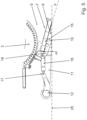
- a vehicle 1 according to the invention is shown purely schematically, designated with the reference number 1.
- the vehicle 1 shown is designed as a truck-mounted concrete pump.
- a pivoting turntable 3 is arranged on the frame 2 of the vehicle 1, on which a multi-section mast 4 is mounted.
- the segments of the mast 4 are folded together via joints 20 for driving operation.
- the mast 4 is unfolded, it is used to distribute concrete on a construction site.
- the concrete is filled via a feed hopper 21 arranged at the rear and pumped via a concrete pump into delivery lines (not shown) on the mast 4 in order to be able to be distributed via an end hose (not shown) arranged at the top of the unfolded mast 4.
- the unfolded mast 4 reaches considerable heights and triggers a tipping moment that depends on the projection and the length of the mast 4.
- the frame support 5 has horizontal supports 6, 6a that can be pulled out from the vehicle profile.
- the mirror-image supports 6, 6a of the frame support 5 are pulled into the vehicle profile.
- the supports 6, 6a are each guided on a vehicle-fixed extension section 7, 7a.
- the supports 6, 6a and the extension sections 7, 7a thus each form a telescope 8, 8a.
- the vehicle-fixed extension sections 7, 7a are arranged in the direction of travel behind a driver's cab 9.
- a folding part 11, 11a is arranged which is connected to the supports 6, 6a via a joint 10, 10a.
- a support leg 12, 12a is arranged on the folding part 11, 11a, which preferably has a vertically telescopic support foot 22, 22a with a support plate.
- the frame support 5 can be supported on the ground via the support foot 22, 22a which is telescoped against the ground. In the illustration shown here, the support 6, 6a is in the retracted transport position.
- the joint 10, 10a is arranged outside the extension section 7, 7a, so that the folding part 11, 11a is folded sideways into the vehicle profile in a transport folding position shown.
- the folding part 11, 11a is folded forwards in the direction of the driver's cab 9.
- the joint 10, 10a for this folding mechanism forms a vertical pivot axis, which is indicated in dash-dotted lines, and is arranged at the free end of the carrier 6, 6a shown and thus connects the folding part 11, 11a to the carrier 6, 6a.
- the support leg 12, 12a is located between the wheel axles 14, 14a of the double steering axle 13, which is located in the direction of travel between the driver's cab 9 and the extension section 7, 7a. From this transport folding position, the folding part 11, 11a can be swiveled sideways before the carrier 6, 6a can be pulled out from the transport position shown here into an extended support position.
- the installation space for the control electronics/hydraulics 33 is not affected by the folding part being folded forwards. Depending on the machine equipment/variant, a tank, tool box or similar could also be accommodated in this area.
- the Figure 2 shows vehicle 1 according to Figure 1 from a bird's eye view.
- the arched support 6 is shown pulled out from the extension section 7.
- the folding part 11 connected to the support 6 via the joint 10 is folded out in the support folding position.
- the arched support 6a is retracted in the extension section 7a in the transport position and the folding part 11a connected to the support 6a via the joint 10a is folded forward in the direction of the driver's cab 9 in the transport folding position so that the folding part 10a located on the side of the vehicle profile.
- FIG 2 A detail of an embodiment is shown in which the folding part 11b is bent from the joint 10a towards the vehicle center 16; a bent version would also be possible, for example.
- This design allows the support leg 12a to be folded even further into the vehicle profile in the transport folding position, so that larger support feet 22, 22a can be used without them protruding laterally beyond the vehicle profile.
- the support leg 12, 12a arranged on the folding part 11, 11a is located between the wheel axles 14, 14a of the double steering axle 13 in the transport folding position shown. From this position, the folding part 11a can first be pivoted into the support folding position before the carrier 6a is pulled out of the extension section 7a. This prevents collisions with the wheel axles 14, 14a.
- the carrier is shown on the left in the direction of travel in the support position pulled out from the extension section 7.
- the folding part 11 is pivoted into the support folding position by a drive 17, which in the embodiment shown here is designed as a hydraulic cylinder 18.
- This drive 18 is designed to hold the folding part 11 in the selected support folding position.
- the hydraulic cylinder 18 of the drive is hinged to a nose 19, which is located at the free end of the carrier 6. By forming this nose 19, the hydraulic cylinder 18 has a sufficient lever arm to pivot the folding part 11 relative to the carrier 6 about the joint 10.
- the two extension sections 7, 7a each have a collar 15, 15a.
- This collar 15, 15a runs in relation to the vehicle profile in the direction of the driver's cab 9 at an angle to the vehicle center 16, so that the collar 15, 15a on its side 28 facing the driver's cab 9 is offset from the vehicle profile in the direction of the vehicle center 16 essentially by the width b of the folding part 11, 11a.
- the collar 15, 15a runs in relation to the vehicle's longitudinal axis in the direction of the driver's cab 9 at an angle of preferably 15 degrees to the vehicle center 16. This makes it easier to fold the folding part 11 forwards into the transport folding position.
- rear folding supports 23, 23a are hinged behind the collars 15, 15a in the direction of travel to support the vehicle 1, with the support 23 being shown unfolded in the support position on the left side in the direction of travel, while the folding support 23a in the direction of travel on the right-hand side in the transport position is folded laterally into the vehicle profile.
- FIG 3 is a perspective view of a detailed view of the support 6 and the folding part 11 connected via the joint 10.
- the support 6 shown here has been pulled out of the extension section 7 and the folding part 11 is in a support-folding position.
- the folding part 11 was pivoted into this support-folding position by means of a drive 17 which is formed by a hydraulic cylinder 18.
- This hydraulic cylinder 18 is hinged to a nose 19 which is located at the free end of the support 6. This gives the hydraulic cylinder 18 a sufficient lever arm to pivot the folding part 11 horizontally around the joint 10 relative to the support 6.
- the folding part 11 is held by the hydraulic cylinder 18, e.g. by a hydraulic lock with non-return valves, so that its position relative to the support 6 does not change.
- the angular position of the folding part can be checked by a suitable sensor (angle measurement, limit switch or similar) on the hydraulic cylinder 18 or the joint 10 to ensure that the folding part 11 is fully extended.
- the hydraulic cylinder 18 can be used to flexibly move the folding part 11 into various support folding positions if necessary in order to adapt the support to the conditions on the construction site.
- the locking of the folding part 11 relative to the support 6 is preferably carried out exclusively via the hydraulic cylinder 18.
- the Figure 4 shows a perspective detailed view of the frame support 5 and the folding part 11.
- the carrier 6 shown here is in the transport position and is retracted into the extension section 7.
- the joint 10 which connects the folding part 11 to the carrier 6 is located outside the extension section 7 in this position.
- the folding part 11 can be folded into the transport folding position shown.
- the collar 15 which runs at an angle in the direction of the driver's cab 9 towards the vehicle center 16, as described above.
- the nose 19 formed on the carrier 6 extends in the direction of the vehicle center 16. This nose 19 allows the rotation axis 24 for the hydraulic cylinder 18 to be positioned as far as possible in the vehicle center 16 in order to provide sufficient installation length and lever arm for the hydraulic cylinder 18 even in the transport folding position shown.
- the Figure 5 shows a bird's eye view of the frame support 5 and the folding part 11 according to Figure 4 .
- the folding part 11 in the transport folding position shown is located within the vehicle profile 25 indicated by dash-dot lines, which indicates the maximum permissible width of the vehicle 1.
- the nose 19 arranged on the carrier 6 leads around the collar 15 of the extension section 7 in the direction of the vehicle center 16 and thus offers sufficient lever arm and installation length for the hydraulic cylinder 18, via which the folding part 11 can be pivoted around the joint 10 from the transport folding position shown into the support folding position.
- the joint 10 between the carrier 6 and the folding part 11 is arranged in the transport position of the carrier 6 in the extension section 7 shown in such a way that it remains outside the extension section 7.
- the collar 15, 15a runs relative to the vehicle profile in the direction of the driver's cab 9 at an angle ⁇ of preferably 15° towards the vehicle center 16. This angle ⁇ is illustrated by another dot-dash line.
- This offset of the collar 15 relative to the long side of the vehicle profile 25 ensures that the folding part 11 can be folded forwards into the transport folding position in the transport position of the carrier 6 in the extension section 7 via the joint 10.
- the support foot 22 on the folding part 11 is slightly offset inwards towards the vehicle centre 16 so that it is located within the vehicle profile when the folding part 11 is in the transport folding position.
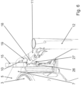
- FIG. 6 shows a perspective detailed view of the frame support 5 and the folding part 11.
- the view shown provides a view behind the Folding part 11 is possible.
- the frame support 5 has a locking lug 26 which engages in an eyelet 27 on the folding part 11 and thus prevents the carrier 6 from being pushed out of the extension section 7 before the folding part 11 has been pivoted from the transport folding position into a support folding position.
- the folding part 11 could also be secured by a locking bolt.
- the Figure 7 shows a perspective detailed view of the joint 10 between the folding part 11 and the support 6.
- a view behind the folding part 11 is possible.
- the joint 10 between the folding part 11 and the support 6 has several joint components 29, 29a, 30.
- the upper and lower joint components 29, 29a are designed to transmit horizontal forces
- the middle joint component 30 is designed to transmit vertical forces.
- the forces to be transmitted are indicated as dot-dash arrows.
- the upper 29a and the lower joint component 29 have bolts to transmit horizontally acting forces.
- the middle joint component 30 is designed without bolts, since only vertically acting forces are transmitted here via support surfaces.
- the Figure 8 shows a joint 10 between folding part 11 and support 6 according to Figure 7 but without force lines drawn in. It can be seen that the middle joint component 30 comprises tapered support beams 32, 32a to support the vertical forces.
- a joint 10 between the folding part 11 and the support 6 is arranged according to the Figures 7 and 8th , but a perspective view has been chosen here.
- the support foot 22 of the support leg 12 is retracted and positioned folded down by a slanting sleeve 31.
- FIG. 1 shows a frame support 5 with curved extension sections 7, 7a and corresponding supports 6, 6a.
- the basic idea of the inventions is also fundamentally applicable, for example, to so-called telescopic X-supports with straight or curved extension sections that cross in front of or behind the turntable or to telescopic supports, where the supports are extended perpendicular to the side of the vehicle.
- the vehicle can also be designed as a so-called truck and trailer concrete pump.
- the driver's cab is part of a towing vehicle, with the frame support being part of a trailer that is articulated to the tractor.
Landscapes
- Engineering & Computer Science (AREA)
- Mechanical Engineering (AREA)
- Physics & Mathematics (AREA)
- Fluid Mechanics (AREA)
- Architecture (AREA)
- Civil Engineering (AREA)
- Structural Engineering (AREA)
- Body Structure For Vehicles (AREA)
- Vehicle Cleaning, Maintenance, Repair, Refitting, And Outriggers (AREA)
- On-Site Construction Work That Accompanies The Preparation And Application Of Concrete (AREA)
Claims (9)
- Véhicule (1), en particulier pompe à béton automotrice, comportant une couronne d'orientation (3) pivotante agencée sur un châssis (2), dotée d'un mât (4) monté sur celle-ci, et un système de support de châssis (5) qui présente des supports (6, 6a) qui peuvent être rentrés dans le profil de véhicule et/ou sortis du profil de véhicule, les supports (6, 6a) étant chacun guidés sur une partie de déploiement (7, 7a) solidaire du véhicule et formant avec celle-ci un dispositif télescopique (8, 8a), les parties de déploiement (7, 7a) solidaires du véhicule étant agencées, dans le sens de la marche, derrière une cabine de conducteur (9), une partie rabattable (11, 11a) reliée par le biais d'une articulation (10, 10a) étant respectivement agencée sur une extrémité libre des supports (6, 6a), une béquille (12, 12a) étant agencée sur chaque partie rabattable (11, 11a), l'articulation (10, 10a) étant, dans la position de transport rentrée des supports (6, 6a), agencée en dehors de la partie de déploiement (7, 7a) respective de telle sorte que la partie rabattable (11, 11a) peut être rabattue latéralement dans le profil de véhicule dans une position rabattue de transport, la partie rabattable (11, 11a) pouvant être rabattue vers l'avant en direction de la cabine de conducteur (9) dans la position rabattue de transport,
caractérisé en ce que
les parties de déploiement (7, 7a) présentent chacune un rebord (15, 15a), ce rebord (15, 15a) s'étendant, par rapport au profil de véhicule, vers le centre du véhicule (16) en direction de la cabine de conducteur (9) de telle sorte que le rebord (15, 15a) présente, sur un côté (28) orienté vers la cabine de conducteur (9), un décalage en direction du centre du véhicule (16) au moins égal à la largeur de la partie rabattable (11, 11a). - Véhicule (1) selon la revendication 1, caractérisé en ce que le véhicule (1) présente, entre la cabine de conducteur (9) et la partie de déploiement (7, 7a), deux essieux (14, 14a) ou plus, les béquilles (12, 12a) agencées sur la partie rabattable (11, 11a) respective étant agencées entre deux essieux (14, 14a) dans la position rabattue de transport.
- Véhicule (1) selon la revendication 1 ou 2, caractérisé en ce que la partie rabattable (11, 11a) peut être pivotée d'une position rabattue de transport à une position dépliée de support avant que le support (6, 6a) en forme d'arc puisse être sorti pour passer de la position de transport rentrée à une position de support sortie.
- Véhicule (1) selon la revendication 3, caractérisé en ce que la partie rabattable (11, 11a) peut être enclenchée dans la position rabattue de transport et/ou dans une position dépliée de support.
- Véhicule (1) selon l'une des revendications 1 à 4, caractérisé en ce que la partie rabattable (11, 11a) peut être pivotée par rapport au support (6, 6a), respectivement au moyen d'un entraînement (17, 17a), de la position rabattue de transport à la position dépliée de support.
- Véhicule (1) selon la revendication 5, caractérisé en ce que l'entraînement (17, 17a) est conçu pour retenir la partie rabattable (11, 11a) dans la position rabattue de transport et/ou dans la position dépliée de support.
- Véhicule (1) selon la revendication 5 ou 6, caractérisé en ce que l'entraînement (17, 17a) comprend un vérin hydraulique (18, 18a), un nez (19, 19a) permettant l'articulation du vérin hydraulique (18, 18a) étant réalisé sur l'extrémité libre du support (6, 6a).
- Véhicule (1) selon les revendications 1 et 7, caractérisé en ce que le nez (19, 19a) passe, dans la position de transport du support (6, 6a), autour du rebord (15, 15a) respectif de la partie de déploiement (7, 7a), en direction du centre du véhicule (16).
- Véhicule (1) selon l'une des revendications 1 à 8, caractérisé en ce que la partie rabattable (11, 11a) est conçue de manière télescopique.
Applications Claiming Priority (1)
| Application Number | Priority Date | Filing Date | Title |
|---|---|---|---|
| DE102017122343.6A DE102017122343A1 (de) | 2017-09-26 | 2017-09-26 | Bogenabstützung mit Klappteil |
Publications (2)
| Publication Number | Publication Date |
|---|---|
| EP3459900A1 EP3459900A1 (fr) | 2019-03-27 |
| EP3459900B1 true EP3459900B1 (fr) | 2024-06-26 |
Family
ID=63683683
Family Applications (1)
| Application Number | Title | Priority Date | Filing Date |
|---|---|---|---|
| EP18196441.2A Active EP3459900B1 (fr) | 2017-09-26 | 2018-09-25 | Support de véhicule avec partie rabattable |
Country Status (4)
| Country | Link |
|---|---|
| US (1) | US10464535B2 (fr) |
| EP (1) | EP3459900B1 (fr) |
| CN (1) | CN109552273B (fr) |
| DE (1) | DE102017122343A1 (fr) |
Families Citing this family (5)
| Publication number | Priority date | Publication date | Assignee | Title |
|---|---|---|---|---|
| US11370482B2 (en) * | 2018-08-30 | 2022-06-28 | Master Solutions, Inc. | Hydraulic steering system |
| DE102019122396B4 (de) * | 2019-08-20 | 2025-03-06 | Ffg Flensburger Fahrzeugbau Gesellschaft Mbh | Fahrzeug mit einem eine Mehrzahl von Fahrzeugstützen aufweisenden Stützsystem |
| CN111336376B (zh) * | 2020-04-13 | 2025-06-24 | 徐州徐工施维英机械有限公司 | 支撑装置以及工程机械 |
| CN115142681B (zh) * | 2021-03-31 | 2023-10-27 | 三一汽车制造有限公司 | 工程机械 |
| US20250019983A1 (en) * | 2023-07-12 | 2025-01-16 | Thomas M. Anderson | Mast mounted screed boom |
Citations (1)
| Publication number | Priority date | Publication date | Assignee | Title |
|---|---|---|---|---|
| KR20150142698A (ko) * | 2013-04-11 | 2015-12-22 | 푸츠마이스터 엔지니어링 게엠베하 | 분배붐 및 지지 장치를 가진 이동식 콘크리트 펌프 |
Family Cites Families (25)
| Publication number | Priority date | Publication date | Assignee | Title |
|---|---|---|---|---|
| US3825095A (en) * | 1972-10-10 | 1974-07-23 | Pac Craft Prod Inc | Aerial scaffold for vehicle |
| CA997748A (en) * | 1973-11-01 | 1976-09-28 | John T. Hornagold | Mounting arrangement for a vertical outrigger cylinder |
| JPS5613243A (en) * | 1979-07-10 | 1981-02-09 | Nissan Diesel Motor Co Ltd | Car body supporter for specially equipped car |
| US4394912A (en) * | 1980-11-07 | 1983-07-26 | Harnischfeger Corporation | Mobile crane having telescoping outriggers and power operated screw means for same |
| US4609204A (en) * | 1982-09-14 | 1986-09-02 | Nekola Randy A | Extension for outrigger beam |
| DE3830315A1 (de) * | 1988-09-07 | 1990-03-08 | Putzmeister Maschf | Fahrbare betonpumpe |
| US5387071A (en) * | 1993-06-29 | 1995-02-07 | Pinkston; Donald L. | Rotatable recovery vehicle |
| DE4344779C2 (de) * | 1993-12-28 | 1999-12-09 | Schwing Gmbh F | Fahrzeug mit schwenkbar aufgebautem Mast und Rahmenabstützung |
| DE19736109A1 (de) * | 1997-08-21 | 1999-02-25 | Putzmeister Ag | Fahrbare Arbeitsmaschine mit teleskopierbaren Stützauslegern |
| DE19736108A1 (de) | 1997-08-21 | 1999-02-25 | Putzmeister Ag | Fahrbare Arbeitsmaschine mit teleskopierbaren Stützauslegern |
| US6276818B1 (en) * | 2000-02-09 | 2001-08-21 | Hubbell Incorporated | Latch assembly for luminaire housing door |
| DE10032622A1 (de) * | 2000-07-07 | 2002-01-17 | Putzmeister Ag | Stützausleger für fahrbare Arbeitsmaschinen und Autobetonpumpen mit solchen Stützauslegern |
| US7594679B1 (en) * | 2005-01-19 | 2009-09-29 | Westchester Captial, Llc | Outrigger for a boom truck or the like |
| US7338077B2 (en) * | 2005-05-27 | 2008-03-04 | Richard Ronnie J | Storage system for a support mat |
| DE102008007917A1 (de) * | 2008-02-06 | 2009-08-13 | Putzmeister Concrete Pumps Gmbh | Fahrbare Arbeitsmaschine |
| CN101301869B (zh) * | 2008-04-28 | 2011-08-24 | 三一重工股份有限公司 | 一种混凝土泵车的支腿以及具有这种支腿的混凝土泵车 |
| CN201825676U (zh) * | 2010-10-20 | 2011-05-11 | 徐州重型机械有限公司 | 一种支腿支撑装置及移动式起重机 |
| CN102491202B (zh) * | 2011-12-05 | 2014-03-05 | 中联重科股份有限公司 | 行车式起重机 |
| CN102493653A (zh) * | 2011-12-21 | 2012-06-13 | 三一重工股份有限公司 | 一种支腿装置及包括该装置的工程机械 |
| KR101334080B1 (ko) * | 2013-03-19 | 2013-12-04 | 최병언 | 아우트리거 후방 절첩식 파일드라이버 |
| JP6231320B2 (ja) * | 2013-07-23 | 2017-11-15 | 株式会社タダノ | アウトリガ連結ロック装置 |
| DE102014006273A1 (de) * | 2014-05-02 | 2015-11-05 | Schwing Gmbh | Abstützung |
| KR20150137903A (ko) * | 2014-05-30 | 2015-12-09 | 한국타워크레인 주식회사 | 차량 탑재용 크레인 아우트리거 장치 |
| CN204297987U (zh) * | 2014-12-12 | 2015-04-29 | 中联重科股份有限公司 | 一种工程机械的支腿装置及工程机械 |
| DE102016104653A1 (de) * | 2016-03-14 | 2017-09-14 | Schwing Gmbh | Doppelt teleskopierbare Bogenabstützung |
-
2017
- 2017-09-26 DE DE102017122343.6A patent/DE102017122343A1/de active Pending
-
2018
- 2018-09-25 EP EP18196441.2A patent/EP3459900B1/fr active Active
- 2018-09-25 US US16/140,944 patent/US10464535B2/en active Active
- 2018-09-26 CN CN201811123433.0A patent/CN109552273B/zh active Active
Patent Citations (1)
| Publication number | Priority date | Publication date | Assignee | Title |
|---|---|---|---|---|
| KR20150142698A (ko) * | 2013-04-11 | 2015-12-22 | 푸츠마이스터 엔지니어링 게엠베하 | 분배붐 및 지지 장치를 가진 이동식 콘크리트 펌프 |
Also Published As
| Publication number | Publication date |
|---|---|
| EP3459900A1 (fr) | 2019-03-27 |
| US10464535B2 (en) | 2019-11-05 |
| US20190092288A1 (en) | 2019-03-28 |
| CN109552273B (zh) | 2022-09-06 |
| CN109552273A (zh) | 2019-04-02 |
| DE102017122343A1 (de) | 2019-03-28 |
Similar Documents
| Publication | Publication Date | Title |
|---|---|---|
| EP3459900B1 (fr) | Support de véhicule avec partie rabattable | |
| EP2931585B1 (fr) | Véhicule de transport à largeur et à voie variables, pourvu d'au moins un essieu directeur | |
| EP2240360B1 (fr) | Engin de travail mobile | |
| EP2238071B1 (fr) | Engin de travail mobile | |
| DE1944214C3 (de) | Schienenlos verfahrbarer Dreh kranunterwagen | |
| CH650299A5 (de) | Schreitbagger. | |
| EP1851159B1 (fr) | Bras d'appui destine a des machines de travail roulantes | |
| EP2917070B1 (fr) | Véhicule de transport de charges lourdes servant au transport d'un objet allongé | |
| DE102012024247B4 (de) | Transportfahrzeug mit variabler Breite und Spurweite und mindestens einer Lenkachse | |
| DE202012010545U1 (de) | Schwerlast-Transportfahrzeug zum Transport eines länglichen Objekts | |
| EP2186713A2 (fr) | Dispositif de ballastage et véhicule agricole équipé avec ce dernier | |
| DE3439048A1 (de) | Kraftheber fuer ein hubgeraet | |
| DE1915825A1 (de) | Bodenbearbeitungsgeraet | |
| DE2845801C2 (fr) | ||
| DE102012021613B4 (de) | Schwerlast-Transportfahrzeug zum Transport eines länglichen Objekts | |
| DE202004011990U1 (de) | Umschlaggerät | |
| DE102010009176A1 (de) | Vorrichtung zum Abstützen von Sonderfahrzeugen, insbesondere von Autobetonpumpen, und Autobetonpumpe mit einer solchen Vorrichtung | |
| WO2004113646A1 (fr) | Pompe a beton transportable a mat distributeur | |
| EP2042410B1 (fr) | Véhicule agricole | |
| DE2808591A1 (de) | Pneumatisches streugeraet | |
| DE2800119B2 (de) | Klappbarer Geräteträger | |
| DE102009033917A1 (de) | Fahrzeug mit ausschwenkbarem Mastarmaufbau | |
| EP3650615B1 (fr) | Pompe à béton automatique | |
| DE102018109224A1 (de) | Autobetonpumpe | |
| DE102020118775A1 (de) | Fahrbarer Kran mit Abstützvorrichtung |
Legal Events
| Date | Code | Title | Description |
|---|---|---|---|
| PUAI | Public reference made under article 153(3) epc to a published international application that has entered the european phase |
Free format text: ORIGINAL CODE: 0009012 |
|
| STAA | Information on the status of an ep patent application or granted ep patent |
Free format text: STATUS: THE APPLICATION HAS BEEN PUBLISHED |
|
| AK | Designated contracting states |
Kind code of ref document: A1 Designated state(s): AL AT BE BG CH CY CZ DE DK EE ES FI FR GB GR HR HU IE IS IT LI LT LU LV MC MK MT NL NO PL PT RO RS SE SI SK SM TR |
|
| AX | Request for extension of the european patent |
Extension state: BA ME |
|
| RIN1 | Information on inventor provided before grant (corrected) |
Inventor name: SEGSCHNEIDER, BERND Inventor name: SACKEN, CHRISTOPH |
|
| STAA | Information on the status of an ep patent application or granted ep patent |
Free format text: STATUS: REQUEST FOR EXAMINATION WAS MADE |
|
| 17P | Request for examination filed |
Effective date: 20190926 |
|
| RBV | Designated contracting states (corrected) |
Designated state(s): AL AT BE BG CH CY CZ DE DK EE ES FI FR GB GR HR HU IE IS IT LI LT LU LV MC MK MT NL NO PL PT RO RS SE SI SK SM TR |
|
| STAA | Information on the status of an ep patent application or granted ep patent |
Free format text: STATUS: EXAMINATION IS IN PROGRESS |
|
| 17Q | First examination report despatched |
Effective date: 20210325 |
|
| GRAP | Despatch of communication of intention to grant a patent |
Free format text: ORIGINAL CODE: EPIDOSNIGR1 |
|
| STAA | Information on the status of an ep patent application or granted ep patent |
Free format text: STATUS: GRANT OF PATENT IS INTENDED |
|
| INTG | Intention to grant announced |
Effective date: 20240312 |
|
| GRAS | Grant fee paid |
Free format text: ORIGINAL CODE: EPIDOSNIGR3 |
|
| GRAA | (expected) grant |
Free format text: ORIGINAL CODE: 0009210 |
|
| STAA | Information on the status of an ep patent application or granted ep patent |
Free format text: STATUS: THE PATENT HAS BEEN GRANTED |
|
| AK | Designated contracting states |
Kind code of ref document: B1 Designated state(s): AL AT BE BG CH CY CZ DE DK EE ES FI FR GB GR HR HU IE IS IT LI LT LU LV MC MK MT NL NO PL PT RO RS SE SI SK SM TR |
|
| REG | Reference to a national code |
Ref country code: GB Ref legal event code: FG4D Free format text: NOT ENGLISH |
|
| REG | Reference to a national code |
Ref country code: CH Ref legal event code: EP |
|
| REG | Reference to a national code |
Ref country code: DE Ref legal event code: R096 Ref document number: 502018014766 Country of ref document: DE |
|
| PG25 | Lapsed in a contracting state [announced via postgrant information from national office to epo] |
Ref country code: BG Free format text: LAPSE BECAUSE OF FAILURE TO SUBMIT A TRANSLATION OF THE DESCRIPTION OR TO PAY THE FEE WITHIN THE PRESCRIBED TIME-LIMIT Effective date: 20240626 |
|
| PG25 | Lapsed in a contracting state [announced via postgrant information from national office to epo] |
Ref country code: FI Free format text: LAPSE BECAUSE OF FAILURE TO SUBMIT A TRANSLATION OF THE DESCRIPTION OR TO PAY THE FEE WITHIN THE PRESCRIBED TIME-LIMIT Effective date: 20240626 Ref country code: HR Free format text: LAPSE BECAUSE OF FAILURE TO SUBMIT A TRANSLATION OF THE DESCRIPTION OR TO PAY THE FEE WITHIN THE PRESCRIBED TIME-LIMIT Effective date: 20240626 |
|
| REG | Reference to a national code |
Ref country code: LT Ref legal event code: MG9D |
|
| PG25 | Lapsed in a contracting state [announced via postgrant information from national office to epo] |
Ref country code: GR Free format text: LAPSE BECAUSE OF FAILURE TO SUBMIT A TRANSLATION OF THE DESCRIPTION OR TO PAY THE FEE WITHIN THE PRESCRIBED TIME-LIMIT Effective date: 20240927 |
|
| PG25 | Lapsed in a contracting state [announced via postgrant information from national office to epo] |
Ref country code: LV Free format text: LAPSE BECAUSE OF FAILURE TO SUBMIT A TRANSLATION OF THE DESCRIPTION OR TO PAY THE FEE WITHIN THE PRESCRIBED TIME-LIMIT Effective date: 20240626 |
|
| REG | Reference to a national code |
Ref country code: NL Ref legal event code: MP Effective date: 20240626 |
|
| PG25 | Lapsed in a contracting state [announced via postgrant information from national office to epo] |
Ref country code: NO Free format text: LAPSE BECAUSE OF FAILURE TO SUBMIT A TRANSLATION OF THE DESCRIPTION OR TO PAY THE FEE WITHIN THE PRESCRIBED TIME-LIMIT Effective date: 20240926 Ref country code: LV Free format text: LAPSE BECAUSE OF FAILURE TO SUBMIT A TRANSLATION OF THE DESCRIPTION OR TO PAY THE FEE WITHIN THE PRESCRIBED TIME-LIMIT Effective date: 20240626 Ref country code: HR Free format text: LAPSE BECAUSE OF FAILURE TO SUBMIT A TRANSLATION OF THE DESCRIPTION OR TO PAY THE FEE WITHIN THE PRESCRIBED TIME-LIMIT Effective date: 20240626 Ref country code: GR Free format text: LAPSE BECAUSE OF FAILURE TO SUBMIT A TRANSLATION OF THE DESCRIPTION OR TO PAY THE FEE WITHIN THE PRESCRIBED TIME-LIMIT Effective date: 20240927 Ref country code: FI Free format text: LAPSE BECAUSE OF FAILURE TO SUBMIT A TRANSLATION OF THE DESCRIPTION OR TO PAY THE FEE WITHIN THE PRESCRIBED TIME-LIMIT Effective date: 20240626 Ref country code: BG Free format text: LAPSE BECAUSE OF FAILURE TO SUBMIT A TRANSLATION OF THE DESCRIPTION OR TO PAY THE FEE WITHIN THE PRESCRIBED TIME-LIMIT Effective date: 20240626 Ref country code: RS Free format text: LAPSE BECAUSE OF FAILURE TO SUBMIT A TRANSLATION OF THE DESCRIPTION OR TO PAY THE FEE WITHIN THE PRESCRIBED TIME-LIMIT Effective date: 20240926 |
|
| PG25 | Lapsed in a contracting state [announced via postgrant information from national office to epo] |
Ref country code: NL Free format text: LAPSE BECAUSE OF FAILURE TO SUBMIT A TRANSLATION OF THE DESCRIPTION OR TO PAY THE FEE WITHIN THE PRESCRIBED TIME-LIMIT Effective date: 20240626 |
|
| PG25 | Lapsed in a contracting state [announced via postgrant information from national office to epo] |
Ref country code: NL Free format text: LAPSE BECAUSE OF FAILURE TO SUBMIT A TRANSLATION OF THE DESCRIPTION OR TO PAY THE FEE WITHIN THE PRESCRIBED TIME-LIMIT Effective date: 20240626 |
|
| PG25 | Lapsed in a contracting state [announced via postgrant information from national office to epo] |
Ref country code: PT Free format text: LAPSE BECAUSE OF FAILURE TO SUBMIT A TRANSLATION OF THE DESCRIPTION OR TO PAY THE FEE WITHIN THE PRESCRIBED TIME-LIMIT Effective date: 20241028 |
|
| PG25 | Lapsed in a contracting state [announced via postgrant information from national office to epo] |
Ref country code: PT Free format text: LAPSE BECAUSE OF FAILURE TO SUBMIT A TRANSLATION OF THE DESCRIPTION OR TO PAY THE FEE WITHIN THE PRESCRIBED TIME-LIMIT Effective date: 20241028 |
|
| PG25 | Lapsed in a contracting state [announced via postgrant information from national office to epo] |
Ref country code: PL Free format text: LAPSE BECAUSE OF FAILURE TO SUBMIT A TRANSLATION OF THE DESCRIPTION OR TO PAY THE FEE WITHIN THE PRESCRIBED TIME-LIMIT Effective date: 20240626 |
|
| PG25 | Lapsed in a contracting state [announced via postgrant information from national office to epo] |
Ref country code: EE Free format text: LAPSE BECAUSE OF FAILURE TO SUBMIT A TRANSLATION OF THE DESCRIPTION OR TO PAY THE FEE WITHIN THE PRESCRIBED TIME-LIMIT Effective date: 20240626 |
|
| PG25 | Lapsed in a contracting state [announced via postgrant information from national office to epo] |
Ref country code: IS Free format text: LAPSE BECAUSE OF FAILURE TO SUBMIT A TRANSLATION OF THE DESCRIPTION OR TO PAY THE FEE WITHIN THE PRESCRIBED TIME-LIMIT Effective date: 20241026 |
|
| PG25 | Lapsed in a contracting state [announced via postgrant information from national office to epo] |
Ref country code: CZ Free format text: LAPSE BECAUSE OF FAILURE TO SUBMIT A TRANSLATION OF THE DESCRIPTION OR TO PAY THE FEE WITHIN THE PRESCRIBED TIME-LIMIT Effective date: 20240626 |
|
| PG25 | Lapsed in a contracting state [announced via postgrant information from national office to epo] |
Ref country code: RO Free format text: LAPSE BECAUSE OF FAILURE TO SUBMIT A TRANSLATION OF THE DESCRIPTION OR TO PAY THE FEE WITHIN THE PRESCRIBED TIME-LIMIT Effective date: 20240626 Ref country code: SK Free format text: LAPSE BECAUSE OF FAILURE TO SUBMIT A TRANSLATION OF THE DESCRIPTION OR TO PAY THE FEE WITHIN THE PRESCRIBED TIME-LIMIT Effective date: 20240626 |
|
| PG25 | Lapsed in a contracting state [announced via postgrant information from national office to epo] |
Ref country code: ES Free format text: LAPSE BECAUSE OF FAILURE TO SUBMIT A TRANSLATION OF THE DESCRIPTION OR TO PAY THE FEE WITHIN THE PRESCRIBED TIME-LIMIT Effective date: 20240626 Ref country code: SM Free format text: LAPSE BECAUSE OF FAILURE TO SUBMIT A TRANSLATION OF THE DESCRIPTION OR TO PAY THE FEE WITHIN THE PRESCRIBED TIME-LIMIT Effective date: 20240626 |
|
| PG25 | Lapsed in a contracting state [announced via postgrant information from national office to epo] |
Ref country code: SM Free format text: LAPSE BECAUSE OF FAILURE TO SUBMIT A TRANSLATION OF THE DESCRIPTION OR TO PAY THE FEE WITHIN THE PRESCRIBED TIME-LIMIT Effective date: 20240626 Ref country code: SK Free format text: LAPSE BECAUSE OF FAILURE TO SUBMIT A TRANSLATION OF THE DESCRIPTION OR TO PAY THE FEE WITHIN THE PRESCRIBED TIME-LIMIT Effective date: 20240626 Ref country code: RO Free format text: LAPSE BECAUSE OF FAILURE TO SUBMIT A TRANSLATION OF THE DESCRIPTION OR TO PAY THE FEE WITHIN THE PRESCRIBED TIME-LIMIT Effective date: 20240626 Ref country code: PL Free format text: LAPSE BECAUSE OF FAILURE TO SUBMIT A TRANSLATION OF THE DESCRIPTION OR TO PAY THE FEE WITHIN THE PRESCRIBED TIME-LIMIT Effective date: 20240626 Ref country code: IS Free format text: LAPSE BECAUSE OF FAILURE TO SUBMIT A TRANSLATION OF THE DESCRIPTION OR TO PAY THE FEE WITHIN THE PRESCRIBED TIME-LIMIT Effective date: 20241026 Ref country code: ES Free format text: LAPSE BECAUSE OF FAILURE TO SUBMIT A TRANSLATION OF THE DESCRIPTION OR TO PAY THE FEE WITHIN THE PRESCRIBED TIME-LIMIT Effective date: 20240626 Ref country code: EE Free format text: LAPSE BECAUSE OF FAILURE TO SUBMIT A TRANSLATION OF THE DESCRIPTION OR TO PAY THE FEE WITHIN THE PRESCRIBED TIME-LIMIT Effective date: 20240626 Ref country code: CZ Free format text: LAPSE BECAUSE OF FAILURE TO SUBMIT A TRANSLATION OF THE DESCRIPTION OR TO PAY THE FEE WITHIN THE PRESCRIBED TIME-LIMIT Effective date: 20240626 |
|
| PG25 | Lapsed in a contracting state [announced via postgrant information from national office to epo] |
Ref country code: IT Free format text: LAPSE BECAUSE OF FAILURE TO SUBMIT A TRANSLATION OF THE DESCRIPTION OR TO PAY THE FEE WITHIN THE PRESCRIBED TIME-LIMIT Effective date: 20240626 |
|
| REG | Reference to a national code |
Ref country code: DE Ref legal event code: R097 Ref document number: 502018014766 Country of ref document: DE |
|
| PG25 | Lapsed in a contracting state [announced via postgrant information from national office to epo] |
Ref country code: DK Free format text: LAPSE BECAUSE OF FAILURE TO SUBMIT A TRANSLATION OF THE DESCRIPTION OR TO PAY THE FEE WITHIN THE PRESCRIBED TIME-LIMIT Effective date: 20240626 |
|
| PG25 | Lapsed in a contracting state [announced via postgrant information from national office to epo] |
Ref country code: MC Free format text: LAPSE BECAUSE OF FAILURE TO SUBMIT A TRANSLATION OF THE DESCRIPTION OR TO PAY THE FEE WITHIN THE PRESCRIBED TIME-LIMIT Effective date: 20240626 |
|
| REG | Reference to a national code |
Ref country code: CH Ref legal event code: PL |
|
| PLBE | No opposition filed within time limit |
Free format text: ORIGINAL CODE: 0009261 |
|
| STAA | Information on the status of an ep patent application or granted ep patent |
Free format text: STATUS: NO OPPOSITION FILED WITHIN TIME LIMIT |
|
| PG25 | Lapsed in a contracting state [announced via postgrant information from national office to epo] |
Ref country code: LU Free format text: LAPSE BECAUSE OF NON-PAYMENT OF DUE FEES Effective date: 20240925 |
|
| 26N | No opposition filed |
Effective date: 20250327 |
|
| REG | Reference to a national code |
Ref country code: BE Ref legal event code: MM Effective date: 20240930 |
|
| PG25 | Lapsed in a contracting state [announced via postgrant information from national office to epo] |
Ref country code: BE Free format text: LAPSE BECAUSE OF NON-PAYMENT OF DUE FEES Effective date: 20240930 |
|
| PG25 | Lapsed in a contracting state [announced via postgrant information from national office to epo] |
Ref country code: CH Free format text: LAPSE BECAUSE OF NON-PAYMENT OF DUE FEES Effective date: 20240930 |
|
| PG25 | Lapsed in a contracting state [announced via postgrant information from national office to epo] |
Ref country code: IE Free format text: LAPSE BECAUSE OF NON-PAYMENT OF DUE FEES Effective date: 20240925 |
|
| PG25 | Lapsed in a contracting state [announced via postgrant information from national office to epo] |
Ref country code: SE Free format text: LAPSE BECAUSE OF FAILURE TO SUBMIT A TRANSLATION OF THE DESCRIPTION OR TO PAY THE FEE WITHIN THE PRESCRIBED TIME-LIMIT Effective date: 20240626 |
|
| PGFP | Annual fee paid to national office [announced via postgrant information from national office to epo] |
Ref country code: DE Payment date: 20250926 Year of fee payment: 8 |
|
| PGFP | Annual fee paid to national office [announced via postgrant information from national office to epo] |
Ref country code: TR Payment date: 20250905 Year of fee payment: 8 |
|
| PGFP | Annual fee paid to national office [announced via postgrant information from national office to epo] |
Ref country code: GB Payment date: 20250923 Year of fee payment: 8 |
|
| PGFP | Annual fee paid to national office [announced via postgrant information from national office to epo] |
Ref country code: FR Payment date: 20250925 Year of fee payment: 8 |
|
| REG | Reference to a national code |
Ref country code: AT Ref legal event code: MM01 Ref document number: 1697561 Country of ref document: AT Kind code of ref document: T Effective date: 20240925 |
|
| PG25 | Lapsed in a contracting state [announced via postgrant information from national office to epo] |
Ref country code: AT Free format text: LAPSE BECAUSE OF NON-PAYMENT OF DUE FEES Effective date: 20240925 |
|
| PG25 | Lapsed in a contracting state [announced via postgrant information from national office to epo] |
Ref country code: CY Free format text: LAPSE BECAUSE OF FAILURE TO SUBMIT A TRANSLATION OF THE DESCRIPTION OR TO PAY THE FEE WITHIN THE PRESCRIBED TIME-LIMIT; INVALID AB INITIO Effective date: 20180925 |
|
| PG25 | Lapsed in a contracting state [announced via postgrant information from national office to epo] |
Ref country code: HU Free format text: LAPSE BECAUSE OF FAILURE TO SUBMIT A TRANSLATION OF THE DESCRIPTION OR TO PAY THE FEE WITHIN THE PRESCRIBED TIME-LIMIT; INVALID AB INITIO Effective date: 20180925 |