EP3467414B1 - Porte pour un appareil électroménager frigorifique pourvue d'un même dispositif permettant le montage dans les rainures latérales des côtés longitudinaux opposés ainsi que dispositif électroménager frigorifique et procédé de fabrication d'une porte - Google Patents
Porte pour un appareil électroménager frigorifique pourvue d'un même dispositif permettant le montage dans les rainures latérales des côtés longitudinaux opposés ainsi que dispositif électroménager frigorifique et procédé de fabrication d'une porte Download PDFInfo
- Publication number
- EP3467414B1 EP3467414B1 EP18189571.5A EP18189571A EP3467414B1 EP 3467414 B1 EP3467414 B1 EP 3467414B1 EP 18189571 A EP18189571 A EP 18189571A EP 3467414 B1 EP3467414 B1 EP 3467414B1
- Authority
- EP
- European Patent Office
- Prior art keywords
- door
- installation region
- groove recess
- embodied
- assembly area
- Prior art date
- Legal status (The legal status is an assumption and is not a legal conclusion. Google has not performed a legal analysis and makes no representation as to the accuracy of the status listed.)
- Active
Links
Images

Classifications
-
- F—MECHANICAL ENGINEERING; LIGHTING; HEATING; WEAPONS; BLASTING
- F25—REFRIGERATION OR COOLING; COMBINED HEATING AND REFRIGERATION SYSTEMS; HEAT PUMP SYSTEMS; MANUFACTURE OR STORAGE OF ICE; LIQUEFACTION SOLIDIFICATION OF GASES
- F25D—REFRIGERATORS; COLD ROOMS; ICE-BOXES; COOLING OR FREEZING APPARATUS NOT OTHERWISE PROVIDED FOR
- F25D23/00—General constructional features
- F25D23/02—Doors; Covers
- F25D23/028—Details
-
- E—FIXED CONSTRUCTIONS
- E05—LOCKS; KEYS; WINDOW OR DOOR FITTINGS; SAFES
- E05D—HINGES OR SUSPENSION DEVICES FOR DOORS, WINDOWS OR WINGS
- E05D11/00—Additional features or accessories of hinges
- E05D11/0081—Additional features or accessories of hinges for transmitting energy, e.g. electrical cable routing
-
- E—FIXED CONSTRUCTIONS
- E05—LOCKS; KEYS; WINDOW OR DOOR FITTINGS; SAFES
- E05D—HINGES OR SUSPENSION DEVICES FOR DOORS, WINDOWS OR WINGS
- E05D3/00—Hinges with pins
- E05D3/02—Hinges with pins with one pin
-
- E—FIXED CONSTRUCTIONS
- E05—LOCKS; KEYS; WINDOW OR DOOR FITTINGS; SAFES
- E05D—HINGES OR SUSPENSION DEVICES FOR DOORS, WINDOWS OR WINGS
- E05D7/00—Hinges or pivots of special construction
- E05D7/02—Hinges or pivots of special construction for use on the right-hand as well as the left-hand side; Convertible right-hand or left-hand hinges
-
- E—FIXED CONSTRUCTIONS
- E05—LOCKS; KEYS; WINDOW OR DOOR FITTINGS; SAFES
- E05D—HINGES OR SUSPENSION DEVICES FOR DOORS, WINDOWS OR WINGS
- E05D7/00—Hinges or pivots of special construction
- E05D7/08—Hinges or pivots of special construction for use in suspensions comprising two spigots placed at opposite edges of the wing, especially at the top and the bottom, e.g. trunnions
- E05D7/081—Hinges or pivots of special construction for use in suspensions comprising two spigots placed at opposite edges of the wing, especially at the top and the bottom, e.g. trunnions the pivot axis of the wing being situated near one edge of the wing, especially at the top and bottom, e.g. trunnions
-
- E—FIXED CONSTRUCTIONS
- E05—LOCKS; KEYS; WINDOW OR DOOR FITTINGS; SAFES
- E05Y—INDEXING SCHEME ASSOCIATED WITH SUBCLASSES E05D AND E05F, RELATING TO CONSTRUCTION ELEMENTS, ELECTRIC CONTROL, POWER SUPPLY, POWER SIGNAL OR TRANSMISSION, USER INTERFACES, MOUNTING OR COUPLING, DETAILS, ACCESSORIES, AUXILIARY OPERATIONS NOT OTHERWISE PROVIDED FOR, APPLICATION THEREOF
- E05Y2900/00—Application of doors, windows, wings or fittings thereof
- E05Y2900/30—Application of doors, windows, wings or fittings thereof for domestic appliances
-
- F—MECHANICAL ENGINEERING; LIGHTING; HEATING; WEAPONS; BLASTING
- F25—REFRIGERATION OR COOLING; COMBINED HEATING AND REFRIGERATION SYSTEMS; HEAT PUMP SYSTEMS; MANUFACTURE OR STORAGE OF ICE; LIQUEFACTION SOLIDIFICATION OF GASES
- F25D—REFRIGERATORS; COLD ROOMS; ICE-BOXES; COOLING OR FREEZING APPARATUS NOT OTHERWISE PROVIDED FOR
- F25D2323/00—General constructional features not provided for in other groups of this subclass
- F25D2323/02—Details of doors or covers not otherwise covered
- F25D2323/022—Doors that can be pivoted either left-handed or right-handed
-
- F—MECHANICAL ENGINEERING; LIGHTING; HEATING; WEAPONS; BLASTING
- F25—REFRIGERATION OR COOLING; COMBINED HEATING AND REFRIGERATION SYSTEMS; HEAT PUMP SYSTEMS; MANUFACTURE OR STORAGE OF ICE; LIQUEFACTION SOLIDIFICATION OF GASES
- F25D—REFRIGERATORS; COLD ROOMS; ICE-BOXES; COOLING OR FREEZING APPARATUS NOT OTHERWISE PROVIDED FOR
- F25D2323/00—General constructional features not provided for in other groups of this subclass
- F25D2323/02—Details of doors or covers not otherwise covered
- F25D2323/024—Door hinges
-
- F—MECHANICAL ENGINEERING; LIGHTING; HEATING; WEAPONS; BLASTING
- F25—REFRIGERATION OR COOLING; COMBINED HEATING AND REFRIGERATION SYSTEMS; HEAT PUMP SYSTEMS; MANUFACTURE OR STORAGE OF ICE; LIQUEFACTION SOLIDIFICATION OF GASES
- F25D—REFRIGERATORS; COLD ROOMS; ICE-BOXES; COOLING OR FREEZING APPARATUS NOT OTHERWISE PROVIDED FOR
- F25D2400/00—General features of, or devices for refrigerators, cold rooms, ice-boxes, or for cooling or freezing apparatus not covered by any other subclass
- F25D2400/36—Visual displays
Definitions
- the invention according to independent claim 1 relates to a door for a household refrigerator with a door leaf which has a first channel trough open laterally in the width direction of the door leaf on a first vertical longitudinal side and a second vertical longitudinal side which is laterally open in the width direction of the door leaf on a second vertical longitudinal side opposite the first vertical longitudinal side has second gutter trough. Furthermore, the invention also relates to a domestic refrigeration appliance with a door of this type, as well as a method for producing a door according to independent claim 15.
- a household refrigerator is known with a door which has recessed grips on opposite longitudinal sides.
- the door can also be hinged on opposite sides and thus opened on the left or right.
- the door has a door leaf which, on a first vertical longitudinal side, is one in the width direction of the
- the door leaf has the door leaf laterally open first channel trough.
- the door leaf On a second vertical longitudinal side opposite the first vertical longitudinal side, the door leaf has a second channel trough open laterally in the width direction of the door leaf.
- the door leaf is a plate-like component of the door and thus represents the body or the basic body of the door.
- the first channel trough has a first assembly area on which a bearing part for a door hinge or a functional part different therefrom can optionally be mounted.
- the second trough has a second assembly area, on which a bearing part for a door hinge or a different functional part can optionally be mounted, a bearing part for a door hinge being mounted in the first assembly area and a functional part different from the bearing part being mounted in the second assembly area wherein the functional part is a component of an electronic display unit.
- the assembly areas are designed in such a way that they make it possible to optionally assemble both a bearing part for a door hinge and a different functional part according to claims 1 and 15 without conversion. It is therefore not necessary to remodel the assembly area if a functional part according to claims 1 and 15 is to be assembled instead of the bearing part or the bearing part is to be assembled instead of such a functional part.
- Such a configuration not only increases the use of identical components on the door leaf itself, but also minimizes the respective assembly effort for the additional components that can be individually attached to the door leaf, in particular in an assembly area.
- An assembly area is therefore also characterized in that it has means which enable a bearing part or a functional component to be assembled according to claims 1 and 15. These can be screw holes, plug-in openings, hooks, brackets, etc., for example. Even other means can be provided.
- the door can also be used with regard to its shoring as a door hinged on one long side or also on the other opposite longitudinal side. It can thus be installed on individual sides of a housing of a household refrigerator, so that a door hinged on the left or right-hand side can be realized here.
- the assembly areas are formed in the channel troughs at the same height as viewed in the height direction of the door. This also enables the simple and quick installation of the above-mentioned additional parts, namely a bearing part for a door hinge or a different functional part according to claims 1 and 15, and in both variants the respective parts can then be installed at the same height.
- the assembly area can only extend partially over the entire height of the door or also over the entire height of the door.
- the assembly areas are designed mirror-symmetrically to a center axis of the door leaf, which is weighted in the height direction of the door.
- Such individual equality of the assembly areas enables these additional parts to be installed quickly and easily in a particularly advantageous manner.
- the respective individual orientation of the additional parts arranged thereon on the opposite long sides is then automatically set correctly.
- This mirror-symmetrical design of the assembly areas is particularly advantageous in that the additional parts are positioned identically both in the depth direction of the door and in the height direction, so that, for example, when assembling a bearing part, both the left-hinged door and the right-hinged door correct location the door is reached in the depth direction and in the height direction of the household refrigerator to the housing of the household refrigerator.
- the functional component is a component of an electronic display unit. It is preferably provided that the functional part is an electronic display unit. As a result, a corresponding positioning can take place in this channel trough itself, so that it is on the one hand protected and arranged in a space-saving manner, but on the other hand can still be seen sufficiently through the laterally open design of the channel trough.
- the functional part in the assembled state is arranged completely within a channel trough.
- the functional component can also be made for the functional component to extend in regions out of the channel trough in the assembled state. For example, this can be the case with an additional attached handle.
- the bearing part in the assembled state is arranged completely within a channel trough. This also enables a protected and space-saving installation.
- the assembly areas are designed in such a way that one and the same functional component is in the first assembly area or the second
- Mounting area is mountable. With this configuration, the number of identical components for creating variants of the door is increased again. The provision of different variants of components of the door is thereby significantly reduced. This reduces both the development effort and the storage capacity for these components.
- the assembly areas are designed such that one and the same bearing part can be mounted in the first assembly area or the second assembly area.
- the first channel trough preferably has a third assembly area on which a bearing part for a door hinge or a different functional part can optionally be mounted, and the second channel trough has a fourth assembly area on which a bearing part for a door hinge or a different functional part can optionally be mounted is.
- the first assembly area in the first channel trough is designed like the fourth assembly area in the second channel trough, and one and the same bearing part can be optionally mounted in the first assembly area or the fourth assembly area.
- the second assembly area in the second channel trough is formed like the third assembly area in the first channel trough, and one and the same bearing part can optionally be mounted in the second assembly area or the third assembly area.
- the first assembly area in the first channel trough is formed like the fourth assembly area in the second channel trough, and one and the same Functional component can optionally be mounted in the first assembly area or the fourth assembly area.
- the second assembly area in the second channel trough is designed like the third assembly area in the first channel trough, and one and the same functional component can optionally be installed in the second assembly area or the third assembly area.
- the first assembly area viewed in the vertical direction of the door, are preferably at at least one upper end of the first channel trough, the second assembly area at least at an upper end of the second channel trough, the third assembly area at least at a lower end of the first channel trough and the fourth assembly area at least a lower end of the second channel trough formed.
- a mounting area is formed on each of the four corner areas of the door, of which mounting areas are formed at least in pairs and / or at specific positions.
- a bearing part or a functional component can preferably be mounted in a non-destructive detachable manner on an assembly area. As a result, these components can easily be exchanged reversibly and installed elsewhere in a different assembly area.
- the functional component is preferably designed in the form of a strip. As a result, it can also be installed in a narrow channel trough and provide a relatively large front surface, so that information can be displayed in a correspondingly extensive manner.
- at least one channel recess can be designed as a grip recess, at least in some areas.
- the channel trough is designed to be multifunctional and yet compact and can be installed on a narrow side or an edge side of the door.
- the functional component extends over at least 50%, in particular at least 60%, in particular at least 70%, in particular at least 80%, in particular at least 90%, in particular at least completely over the vertical length of a channel trough.
- Another aspect of the invention relates to a method for producing a door for a household refrigerator, with a door leaf on which a first channel trough open laterally in the width direction of the door leaf is formed on a first vertical longitudinal side, and on a second vertical longitudinal side opposite the first vertical longitudinal side a second gutter trough is formed laterally in the width direction of the door leaf, the first gutter trough being formed with a first assembly area on which either a bearing part for a door hinge or a different functional part is mounted, and the second gutter trough is formed with a second assembly area, on which either a bearing part for a door hinge or a different functional part is mounted, the functional part that can be mounted on the first assembly area or the second assembly area being a component of an electronic display unit.
- bearing part is mounted on the first assembly area or the second assembly area.
- the bearing part as an identical component can thus be mounted in two assembly areas that are designed to be compatible with the installation of the bearing part. This makes it easy to convert the door and thus create a variant. Both the equipping of the door with specific components and the installation location of these specific components are therefore flexible. This enables a door that can be hinged on a first side on a stop side of a housing of the domestic refrigerator or can be installed hinged on a second stop side of the housing.
- the first channel trough is preferably designed with a third assembly area on which either a bearing part for a door hinge or a different functional part is mounted, and the second channel trough is preferably designed with a fourth assembly area on which a bearing part for a door hinge or a different functional part is mounted. This enables the door to be easily converted.
- the first assembly area in the first channel trough can be formed like the fourth assembly area in the second channel trough, and one and the same bearing part is then optionally installed in the first assembly area or the fourth assembly area. It can also be provided that the second assembly area in the second channel trough is formed like the third assembly area in the first channel trough, and one and the same bearing part is optionally installed in the second assembly area or the third assembly area. In this way, the door can also be easily modified in order to attach it to a housing with different hinges.
- the first assembly area in the first channel trough is preferably formed like the fourth assembly area in the second channel trough, and one and the same functional component according to claims 1 and 15 is optionally installed in the first assembly area or the fourth assembly area.
- the second assembly area in the second channel trough is formed like the third assembly area in the first channel trough, and one and the same functional component according to claims 1 and 15 is optionally installed in the second assembly area or the third assembly area . This also makes it possible to create variants of the door quickly and easily. In particular, there are also different options for equipping the door with a maximum number of identical components.
- the first assembly area is preferably at an upper end of the first channel trough, the second assembly area at an upper end of the second channel trough, the third assembly area at a lower end of the first channel trough and the fourth assembly area at a lower end of the second channel trough formed.
- Another aspect of the invention relates to a household refrigerator with a door according to the above aspect or an advantageous embodiment thereof.
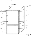
- a household refrigerator 1 in a schematic representation, which is designed for storing and preserving food.
- the household refrigerator 1 has a housing 2 in which at least one receiving space for food, for example a refrigerator compartment or a freezer compartment, is formed.
- a first receiving space is formed in the housing 2, which can be a cooling compartment and which can be closed at the front by a first door 3.
- the first door 3 is arranged pivotably on the housing 2.
- a second receiving space that is separate from the first receiving space and is a freezer compartment can be closed by a second door 4 that is separate from the first door 3.
- the second door 4 is also pivotably arranged on the housing 2.
- the two doors 3 and 4 are designed on the front and represent in particular front parts or also visible parts of the household refrigerator 1. They are in particular in the closed state, as shown in FIG Fig. 1 is shown, arranged in a vertical plane to one another.
- the first door 3 has a door leaf 5, which is a plate-like part and represents a base part or a base body of the door 3.
- the door leaf 5 has a first longitudinal side 6, which is a vertical longitudinal side, and has an opposite, second longitudinal side 7.
- a first channel trough 8 is formed on the first longitudinal side 6 and, in particular, a second channel trough 9 is formed on the second longitudinal side 7.
- the second door 4 is preferably designed accordingly and has a channel trough 11 on a first longitudinal side 10 and a channel trough 13 on an opposite, second longitudinal side 12.
- the channel troughs 11 and 13 are designed to be open laterally (in the width direction (x direction)).
- the channel troughs 8 and 9 can extend in the height direction (y-direction) of the door 3 and also of the household refrigerator 1 over the entire height of the door 3. The same can also be provided for the door 4.
- a partial area of the household refrigerator 1 is shown in a perspective view.
- the door 3 with the door leaf 5 is shown here.
- a first assembly area 14 is formed in the first channel trough 8.
- the first assembly area 14 is designed in such a way that it is designed to assemble a bearing part 15, which represents a separate component, or a separate functional part 16 different therefrom, according to claims 1 and 15, without re-assembly.
- the bearing part 15 is for receiving a door hinge 17, which in Fig. 2 is also drawn, formed. In the assembled state, the door hinge 17 engages with a bearing pin 18 in a receptacle 19 of the bearing part 15.
- the L-shaped door hinge 17 is fastened to the housing 2 with a mounting plate 20, in particular screwed on.
- the functional part 16 is, for example, a cover for an electronic module of a display unit and, according to the present invention, is part of an electronic display unit.
- the functional component is designed in particular as an elongated strip or as a bar.
- the door leaf 5 also has a second assembly area 21 on the opposite longitudinal side 7 in the second channel trough 9 there.
- the second assembly area 21 is also designed for optional assembly, without the assembly area 21 having to be rebuilt, of the bearing part or, optionally, of a different functional part according to claims 1 and 15.
- the bearing part 15 or, optionally, the functional part 16 according to claims 1 and 15 can also be installed here in the second assembly area 21.
- the articulated arm or the door hinge 17 can also be mounted on the right-hand side, as is indicated by the corresponding exemplary screw holes 22.
- the first assembly area 14 and the second assembly area 21 are designed mirror-symmetrically to a central axis A in an advantageous embodiment.
- the center axis A is directed in the height direction (y direction) of the door 5.
- the two assembly areas 14 and 21 are formed completely within the channel troughs 8 and 9, which are open laterally in the width direction (x-direction), and are thus sunk and designed to lie completely therein.
- the assembly areas 14 and 21 are formed in the upper area of the channel troughs 8 and 9, viewed in the vertical direction.
- the channel troughs 8 and 9 are, as shown in Fig. 2 to can be seen, in the vertical direction upwards and thus preferably open towards the upper edge of the door leaf 5.
- the assembly areas 14 and 21 are designed such that the bearing part 15 in the assembled state, viewed in the width direction of the door leaf 5, is arranged completely within a channel trough 8 or 9. The same is provided if a functional part 16 according to claims 1 and 15 is installed in an assembly area 14, 21.
- the bearing part 15 is installed in the channel trough 8 on the left.
- the functional part 16 according to claims 1 and 15 is installed on the opposite longitudinal side 9 in the second channel trough 9 there in the second assembly area 21.
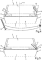
- Fig. 4 is in a corresponding perspective illustration as in Fig. 2 a variant of the door 3 and thus also a variant of the household refrigerator 1 is shown.
- the door 3 when viewed from the front of the household refrigerator 1, is a door hinged on the right.
- the bearing part 15 used as an identical component is provided here in the second assembly area 21 for installation.
- Fig. 4 the exploded view of the respective separate components is shown in this regard.
- Fig. 5 the assembled state of these components is shown.
- the bearing part 15 is for the FIGS. 2 to 5 explained variants provided as an identical component.
- the functional part 16 according to claims 1 and 15 for the to FIGS. 2 to 5 explained variants provided as an identical component. The same can be provided for the component 17.
- FIG. 1 In a further preferred embodiment, further assembly areas 23 and 24 are formed. These further assembly areas 23 and 24 are also designed for each optional attachment of a bearing part 15 or a functional part 16.
- the here third assembly area 23 is formed here in the first channel trough 8.
- the first assembly area 14 is formed in an upper end of the first channel trough 8.
- the third assembly area 23 is formed in a lower end of the first channel trough 8.
- the fourth assembly area 24 is here preferably formed in a lower end of the second channel trough 9.
- the second assembly area 21 is formed here in an upper end of the second channel trough 9.
- a bearing part 15 can be installed, for example, in the first assembly area 14 in a non-destructive detachable manner.
- the same bearing part 15 can, however, also be installed on the fourth assembly area 24 in order to enable an installation variant of the door 3.
- This enables the door 3 to be installed on the housing 2 as a door 3 hinged on the left or as a door 3 hinged on the right.
- a bearing part 15 can be installed as an identical component both in the second assembly area 21 and in the third assembly area 23.
- the assembly areas 14, 21, 23, 24 formed here in particular in the area of the corners of the square door 3, viewed at least crosswise, are designed for compatible accommodation of a common component in the form of a bearing part 15 or a functional part 16 according to claims 1 and 15 .
- channel troughs 8 and 9 are here preferably formed continuously from the upper end to the lower end, an assembly area 14, 21, 23, 24 can also extend over this entire height.
- a functional part 16 according to claims 1 and 15 can also extend over the entire height of a channel trough 8, 9, for example.
- a channel trough 8, 9 can also be designed, at least in some areas, as a gripping trough for engaging with fingers.
Landscapes
- Engineering & Computer Science (AREA)
- Chemical & Material Sciences (AREA)
- Combustion & Propulsion (AREA)
- Physics & Mathematics (AREA)
- Mechanical Engineering (AREA)
- Thermal Sciences (AREA)
- General Engineering & Computer Science (AREA)
- Refrigerator Housings (AREA)
- Casings For Electric Apparatus (AREA)
Claims (15)
- Porte (3, 4) pour un appareil frigorifique électroménager (1), avec un panneau de porte (5), qui présente au niveau d'une première face longitudinale verticale (6) une première cavité de rainure ouverte latéralement (8) dans la direction de la largeur (x) du panneau de porte (5) et une seconde cavité de rainure ouverte latéralement (9) dans la direction de la largeur (x) du panneau de porte (5) au niveau d'une seconde face longitudinale verticale (7) opposée à la première face longitudinale verticale (6), dans laquelle la première cavité de rainure (8) présente une première zone de montage (14) au niveau de laquelle facultativement une partie de support (15) pour une charnière de porte ou une partie fonctionnelle (16) qui diffère de celle-ci peut être montée, et la seconde cavité de rainure (9) présente une seconde zone de montage (21) au niveau de laquelle facultativement une partie de support (15) pour une charnière de porte ou une partie fonctionnelle (16) qui diffère de celle-ci peut être montée, dans laquelle dans la première zone de montage (14) une partie de support (15) pour une charnière de porte est montée et dans la seconde zone de montage (21) une partie fonctionnelle (16) qui diffère de la partie de support (15) est montée, caractérisée en ce que la partie fonctionnelle (16) est un composant d'une unité d'affichage électronique.
- Porte (3, 4) selon la revendication 1, caractérisée en ce que les zones de montage (14, 21) sont réalisées à la même hauteur dans les cavités de rainure (8, 9).
- Porte (3, 4) selon la revendication 1 ou 2, caractérisée en ce que les zones de montage (14, 21) sont réalisées de manière symétrique à un axe central (A) qui est orienté dans la direction de la hauteur (y) de la porte (3, 4), du panneau de porte (5).
- Porte (3, 4) selon l'une quelconque des revendications précédentes, caractérisée en ce que la partie fonctionnelle (16) est disposée entièrement à l'intérieur d'une cavité de rainure (8, 9) à l'état monté.
- Porte (3, 4) selon l'une quelconque des revendications précédentes, caractérisée en ce que la partie de support (15) est disposée entièrement à l'intérieur d'une cavité de rainure (8, 9) à l'état monté.
- Porte (3, 4) selon l'une quelconque des revendications précédentes, caractérisée en ce que les zones de montage (14, 21) sont réalisées de sorte qu'une seule et même partie fonctionnelle (16) peut être montée dans la première zone de montage (14) ou la deuxième zone de montage (21).
- Porte (3, 4) selon l'une quelconque des revendications précédentes, caractérisée en ce que la première cavité de rainure (8) présente une troisième zone de montage (23) au niveau de laquelle facultativement une partie de support (15) peut être montée pour une charnière de porte ou une partie fonctionnelle (16) qui diffère de celle-ci, et la seconde cavité de rainure (9) présente une quatrième zone de montage (24) au niveau de laquelle facultativement une partie de support (15) peut être montée pour une charnière de porte ou une partie fonctionnelle (16) qui diffère de celle-ci.
- Porte (3, 4) selon la revendication 7, caractérisée en ce que la première zone de montage (14) est réalisée dans la première cavité de rainure (8) de manière identique à la quatrième zone de montage (24) dans la deuxième cavité de rainure (9), et une seule et même partie de support (15) peut être montée facultativement dans la première zone de montage (14) ou la quatrième zone de montage (24), et/ou la deuxième zone de montage (21) est réalisée dans la deuxième cavité de rainure (9) de manière identique à la troisième zone de montage (23) dans la première cavité de rainure (8), et une seule et même partie de support (15) peut être montée facultativement dans la deuxième zone de montage (21) ou la troisième zone de montage (23).
- Porte (3, 4) selon la revendication 7 ou 8, caractérisée en ce que la première zone de montage (14) est réalisée dans la première cavité de rainure (8) de manière identique à la quatrième zone de montage (24) dans la deuxième cavité de rainure (9), et un seul et même composant fonctionnel (16) peut être monté facultativement dans la première zone de montage (14) ou la quatrième zone de montage (24), et/ou la deuxième zone de montage (21) est réalisée dans la deuxième cavité de rainure (9) de manière identique à la troisième zone de montage (23) dans la première cavité de rainure (8), et un seul et même composant fonctionnel (16) peut être monté facultativement dans la deuxième zone de montage (21) ou la troisième zone de montage (23).
- Porte (3, 4) selon l'une quelconque des revendications précédentes 7 à 9, caractérisée en ce que la première zone de montage (14), observée dans la direction de la hauteur (y) de la porte (3, 4), est réalisée au niveau d'une extrémité supérieure de la première cavité de rainure (8), la deuxième zone de montage (21) est réalisée au niveau d'une extrémité supérieure de la deuxième cavité de rainure (9), la troisième zone de montage (23) est réalisée au niveau d'une extrémité inférieure de la première cavité de rainure (8) et la quatrième zone de montage (24) est réalisée au niveau d'une extrémité inférieure de la deuxième cavité de rainure (9).
- Porte (3, 4) selon l'une quelconque des revendications précédentes, caractérisée en ce que les zones de montage (14, 21) sont réalisées de sorte qu'une seule et même partie de support (15) peut être montée dans une des zones de montage (14, 21, 23, 24) ou dans une autre des zones de montage (14, 21, 23, 24).
- Porte (3, 4) selon l'une quelconque des revendications précédentes, caractérisée en ce qu'une partie de support (15) ou un composant fonctionnel (16) peuvent être montés sans dommage de manière amovible au niveau d'une zone de montage (14, 21, 23, 24).
- Porte (3, 4) selon l'une quelconque des revendications précédentes, caractérisée en ce que le composant fonctionnel (16) est réalisé en forme de barrette et/ou au moins une cavité de rainure (8, 9) est réalisée au moins par endroits en tant que cavité de préhension.
- Appareil frigorifique électroménager (1) avec une porte (3, 4) selon l'une quelconque des revendications précédentes.
- Procédé destiné à fabriquer une porte (3, 4) selon la revendication 1 pour un appareil frigorifique électroménager (1), avec un panneau de porte (5), au niveau duquel une première cavité de rainure (8) ouverte latéralement dans la direction de la largeur (x) du panneau de porte (5) au niveau d'une première face longitudinale verticale (6) est réalisée, et au niveau d'une seconde face longitudinale (7) opposée à la première face longitudinale verticale (6) une seconde cavité de rainure (9) ouverte latéralement dans la direction de la largeur (x) du panneau de porte (5) est réalisée, dans lequel la première cavité de rainure (8) est réalisée avec une première zone de montage (14), au niveau de laquelle facultativement une partie de support (15) pour une charnière de porte ou un partie fonctionnelle (16) qui diffère de celle-ci, qui est un composant d'une unité d'affichage électronique, est montée, et la seconde cavité de rainure (9) est réalisée avec une seconde zone de montage (21) au niveau de laquelle facultativement une partie de support (15) pour une charnière de porte ou une partie fonctionnelle (16) qui diffère de celle-ci, qui est un composant d'une unité d'affichage électronique, est montée.
Applications Claiming Priority (1)
| Application Number | Priority Date | Filing Date | Title |
|---|---|---|---|
| DE102017217632.6A DE102017217632A1 (de) | 2017-10-04 | 2017-10-04 | Tür für ein Haushaltskältegerät mit gleicher Montagevorrichtung in seitlichen Rinnen von gegenüberliegenden Längsseiten, sowie Haushaltskältegerät und Verfahren zum Herstellen einer Tür |
Publications (2)
| Publication Number | Publication Date |
|---|---|
| EP3467414A1 EP3467414A1 (fr) | 2019-04-10 |
| EP3467414B1 true EP3467414B1 (fr) | 2021-08-04 |
Family
ID=63311830
Family Applications (2)
| Application Number | Title | Priority Date | Filing Date |
|---|---|---|---|
| EP18189571.5A Active EP3467414B1 (fr) | 2017-10-04 | 2018-08-17 | Porte pour un appareil électroménager frigorifique pourvue d'un même dispositif permettant le montage dans les rainures latérales des côtés longitudinaux opposés ainsi que dispositif électroménager frigorifique et procédé de fabrication d'une porte |
| EP18194703.7A Withdrawn EP3467416A1 (fr) | 2017-10-04 | 2018-09-17 | Appareil électroménager |
Family Applications After (1)
| Application Number | Title | Priority Date | Filing Date |
|---|---|---|---|
| EP18194703.7A Withdrawn EP3467416A1 (fr) | 2017-10-04 | 2018-09-17 | Appareil électroménager |
Country Status (2)
| Country | Link |
|---|---|
| EP (2) | EP3467414B1 (fr) |
| DE (1) | DE102017217632A1 (fr) |
Families Citing this family (6)
| Publication number | Priority date | Publication date | Assignee | Title |
|---|---|---|---|---|
| DE102019113461A1 (de) * | 2019-04-18 | 2020-10-22 | Liebherr-Hausgeräte Ochsenhausen GmbH | Kühl- und/oder Gefriergerät |
| DE102020109618A1 (de) | 2020-02-14 | 2021-08-19 | Liebherr-Hausgeräte Ochsenhausen GmbH | Kühl- und/oder Gefriergerät mit Steuerelektronik neben der Tür |
| DE102020208158A1 (de) | 2020-06-30 | 2021-12-30 | BSH Hausgeräte GmbH | Haushaltsgerät mit einem Verschlusselement und einer spezifisch geformten Griffmulde an einer Schmalseite des Verschlusselements |
| CN116348724A (zh) * | 2020-11-18 | 2023-06-27 | 三星电子株式会社 | 冰箱 |
| DE102021208921A1 (de) | 2021-08-13 | 2023-02-16 | BSH Hausgeräte GmbH | Beidseitig anschlagbare Tür mit spezifischen Montagebereich und optischer Griffseitenanzeige, sowie Haushaltskältegerät |
| US20260029186A1 (en) * | 2024-07-23 | 2026-01-29 | Haier Us Appliance Solutions, Inc. | Locator rail for appliance door hinge |
Family Cites Families (14)
| Publication number | Priority date | Publication date | Assignee | Title |
|---|---|---|---|---|
| FR2527848A2 (fr) * | 1982-05-28 | 1983-12-02 | Thomson Brandt | Dispositif d'alimentation electrique d'un circuit d'utilisation place dans une porte pivotante de meuble, notamment un refrigerateur |
| JPH04136491U (ja) * | 1991-06-07 | 1992-12-18 | 振興 甘 | 双方向式冷蔵庫扉 |
| IT233950Y1 (it) * | 1994-07-20 | 2000-02-16 | Whirlpool Italia | Organo di cerniera in particolare per porte di elettrodomestici, applicabile sia su porte con apertura a destra che su porte con |
| TR200202566A2 (tr) * | 2002-11-22 | 2004-06-21 | Vestel Beyaz E�Ya Sanay� Ve T�Caret A.�. | Açma yönü değiştirilebilen kapıya sahip elektronik kontrollü soğutucu. |
| US20070204648A1 (en) * | 2006-03-03 | 2007-09-06 | Smale Jeffrey J | Step-down top hinge for refrigerator door with external dispenser |
| JP4828346B2 (ja) * | 2006-08-01 | 2011-11-30 | 株式会社ニシムラ | 左右兼用ピボットヒンジ |
| EP2236962B1 (fr) * | 2008-08-26 | 2015-04-08 | Panasonic Corporation | Réfrigérateur |
| DE102008044132A1 (de) * | 2008-11-27 | 2010-06-02 | BSH Bosch und Siemens Hausgeräte GmbH | Kältegerät mit zweiseitig anschlagbarer Tür |
| WO2010085117A2 (fr) * | 2009-01-23 | 2010-07-29 | 엘지전자 주식회사 | Machine de traitement du linge |
| DE102012200810A1 (de) * | 2012-01-20 | 2013-07-25 | BSH Bosch und Siemens Hausgeräte GmbH | Kältegerät mit in der Tür angeordneter Benutzerschnittstelle |
| DE102012200813A1 (de) * | 2012-01-20 | 2013-07-25 | BSH Bosch und Siemens Hausgeräte GmbH | Wärmedämmende Tür für ein Kältegerät |
| DE102015209258A1 (de) | 2015-05-20 | 2016-11-24 | BSH Hausgeräte GmbH | Haushaltskältegerät mit einem eine Schwenkachse aufweisenden türseitigen Lagerteil und einer außerhalb der seitlichen Griffmulde angeordneten Schwenkachse |
| JP6265950B2 (ja) * | 2015-07-31 | 2018-01-24 | 三菱電機エンジニアリング株式会社 | 保存庫 |
| KR101954874B1 (ko) * | 2016-01-05 | 2019-05-30 | 엘지전자 주식회사 | 냉장고 |
-
2017
- 2017-10-04 DE DE102017217632.6A patent/DE102017217632A1/de not_active Withdrawn
-
2018
- 2018-08-17 EP EP18189571.5A patent/EP3467414B1/fr active Active
- 2018-09-17 EP EP18194703.7A patent/EP3467416A1/fr not_active Withdrawn
Also Published As
| Publication number | Publication date |
|---|---|
| EP3467416A1 (fr) | 2019-04-10 |
| EP3467414A1 (fr) | 2019-04-10 |
| DE102017217632A1 (de) | 2019-04-04 |
Similar Documents
| Publication | Publication Date | Title |
|---|---|---|
| EP3467414B1 (fr) | Porte pour un appareil électroménager frigorifique pourvue d'un même dispositif permettant le montage dans les rainures latérales des côtés longitudinaux opposés ainsi que dispositif électroménager frigorifique et procédé de fabrication d'une porte | |
| DE60301799T2 (de) | Vorrichtung zum Anordnen und Auslieferung von Komponenten | |
| EP2059145B1 (fr) | Tiroir | |
| EP3371531B1 (fr) | Porte comportant un cadre de porte et un élément poignée encastré et appareil frigorifique comportant une telle porte | |
| EP1926953B1 (fr) | Porte pour un appareil électroménager | |
| DE3405343C2 (fr) | ||
| WO2014048814A1 (fr) | Porte pour un appareil ménager et appareil ménager pour préparer des produits alimentaires doté d'une porte | |
| EP1926949B1 (fr) | Carcasse d'appareil ménager | |
| EP4022158B1 (fr) | Meuble, en particulier armoire | |
| EP3189749B1 (fr) | Guidage télescopique pour une partie de meuble mobile | |
| WO2005113923A1 (fr) | Poignee encastree | |
| DE102019208449A1 (de) | Lebensmittel-Aufnahmebehälter mit einer auf unterschiedlichen Höhenlagen in verschiedenen Raumrichtungen gehaltenen Trennwand, sowie Verfahren zur Montage einer Trennwand | |
| EP2281159B1 (fr) | Porte pour appareil ménager | |
| EP3757464B1 (fr) | Boîtier à suspendre au mur | |
| EP1454026B1 (fr) | Plaque de montage pour la fixation reglable de charnieres de meuble sur le corps de meubles | |
| DE29921641U1 (de) | Haushalts-Einbaukühlschrank mit Vorrichtungen zur Feinregulierung der Position der vorderen Abdeckplatten | |
| DE102006039025A1 (de) | Führungsbeschlag eines Schiebetürbeschlags | |
| DE102022203496A1 (de) | Tür für ein Haushaltsgerät mit seitlich an ein Türblatt anmündenden drehbaren Griff, sowie Haushaltsgerät | |
| EP2758718B1 (fr) | Appareil de cuisson avec une porte | |
| EP1926952B1 (fr) | Porte pour appareil frigorifique | |
| DE202019106034U1 (de) | Gehäuse zur Aufnahme einer wärmeabgebenden elektrischen Komponente | |
| DE202018105626U1 (de) | Deckelbeschlag zum schwenkbaren Befestigen eines Deckels an einen Möbelkorpus und Möbel mit einem solchen Deckelbeschlag | |
| DE29813644U1 (de) | Kühlgerät mit Tragboden | |
| EP3556977B1 (fr) | Élément de cadre pour un cadre de meuble et meuble | |
| DE102004025755A1 (de) | Schublade |
Legal Events
| Date | Code | Title | Description |
|---|---|---|---|
| PUAI | Public reference made under article 153(3) epc to a published international application that has entered the european phase |
Free format text: ORIGINAL CODE: 0009012 |
|
| STAA | Information on the status of an ep patent application or granted ep patent |
Free format text: STATUS: THE APPLICATION HAS BEEN PUBLISHED |
|
| AK | Designated contracting states |
Kind code of ref document: A1 Designated state(s): AL AT BE BG CH CY CZ DE DK EE ES FI FR GB GR HR HU IE IS IT LI LT LU LV MC MK MT NL NO PL PT RO RS SE SI SK SM TR |
|
| AX | Request for extension of the european patent |
Extension state: BA ME |
|
| STAA | Information on the status of an ep patent application or granted ep patent |
Free format text: STATUS: REQUEST FOR EXAMINATION WAS MADE |
|
| 17P | Request for examination filed |
Effective date: 20191010 |
|
| RBV | Designated contracting states (corrected) |
Designated state(s): AL AT BE BG CH CY CZ DE DK EE ES FI FR GB GR HR HU IE IS IT LI LT LU LV MC MK MT NL NO PL PT RO RS SE SI SK SM TR |
|
| GRAP | Despatch of communication of intention to grant a patent |
Free format text: ORIGINAL CODE: EPIDOSNIGR1 |
|
| STAA | Information on the status of an ep patent application or granted ep patent |
Free format text: STATUS: GRANT OF PATENT IS INTENDED |
|
| INTG | Intention to grant announced |
Effective date: 20210312 |
|
| GRAS | Grant fee paid |
Free format text: ORIGINAL CODE: EPIDOSNIGR3 |
|
| GRAA | (expected) grant |
Free format text: ORIGINAL CODE: 0009210 |
|
| STAA | Information on the status of an ep patent application or granted ep patent |
Free format text: STATUS: THE PATENT HAS BEEN GRANTED |
|
| AK | Designated contracting states |
Kind code of ref document: B1 Designated state(s): AL AT BE BG CH CY CZ DE DK EE ES FI FR GB GR HR HU IE IS IT LI LT LU LV MC MK MT NL NO PL PT RO RS SE SI SK SM TR |
|
| REG | Reference to a national code |
Ref country code: GB Ref legal event code: FG4D Free format text: NOT ENGLISH |
|
| REG | Reference to a national code |
Ref country code: AT Ref legal event code: REF Ref document number: 1417372 Country of ref document: AT Kind code of ref document: T Effective date: 20210815 |
|
| REG | Reference to a national code |
Ref country code: CH Ref legal event code: EP |
|
| REG | Reference to a national code |
Ref country code: DE Ref legal event code: R096 Ref document number: 502018006404 Country of ref document: DE |
|
| REG | Reference to a national code |
Ref country code: IE Ref legal event code: FG4D Free format text: LANGUAGE OF EP DOCUMENT: GERMAN |
|
| REG | Reference to a national code |
Ref country code: LT Ref legal event code: MG9D |
|
| REG | Reference to a national code |
Ref country code: NL Ref legal event code: MP Effective date: 20210804 |
|
| PG25 | Lapsed in a contracting state [announced via postgrant information from national office to epo] |
Ref country code: HR Free format text: LAPSE BECAUSE OF FAILURE TO SUBMIT A TRANSLATION OF THE DESCRIPTION OR TO PAY THE FEE WITHIN THE PRESCRIBED TIME-LIMIT Effective date: 20210804 Ref country code: FI Free format text: LAPSE BECAUSE OF FAILURE TO SUBMIT A TRANSLATION OF THE DESCRIPTION OR TO PAY THE FEE WITHIN THE PRESCRIBED TIME-LIMIT Effective date: 20210804 Ref country code: ES Free format text: LAPSE BECAUSE OF FAILURE TO SUBMIT A TRANSLATION OF THE DESCRIPTION OR TO PAY THE FEE WITHIN THE PRESCRIBED TIME-LIMIT Effective date: 20210804 Ref country code: SE Free format text: LAPSE BECAUSE OF FAILURE TO SUBMIT A TRANSLATION OF THE DESCRIPTION OR TO PAY THE FEE WITHIN THE PRESCRIBED TIME-LIMIT Effective date: 20210804 Ref country code: RS Free format text: LAPSE BECAUSE OF FAILURE TO SUBMIT A TRANSLATION OF THE DESCRIPTION OR TO PAY THE FEE WITHIN THE PRESCRIBED TIME-LIMIT Effective date: 20210804 Ref country code: LT Free format text: LAPSE BECAUSE OF FAILURE TO SUBMIT A TRANSLATION OF THE DESCRIPTION OR TO PAY THE FEE WITHIN THE PRESCRIBED TIME-LIMIT Effective date: 20210804 Ref country code: BG Free format text: LAPSE BECAUSE OF FAILURE TO SUBMIT A TRANSLATION OF THE DESCRIPTION OR TO PAY THE FEE WITHIN THE PRESCRIBED TIME-LIMIT Effective date: 20211104 Ref country code: NO Free format text: LAPSE BECAUSE OF FAILURE TO SUBMIT A TRANSLATION OF THE DESCRIPTION OR TO PAY THE FEE WITHIN THE PRESCRIBED TIME-LIMIT Effective date: 20211104 Ref country code: PT Free format text: LAPSE BECAUSE OF FAILURE TO SUBMIT A TRANSLATION OF THE DESCRIPTION OR TO PAY THE FEE WITHIN THE PRESCRIBED TIME-LIMIT Effective date: 20211206 |
|
| PG25 | Lapsed in a contracting state [announced via postgrant information from national office to epo] |
Ref country code: PL Free format text: LAPSE BECAUSE OF FAILURE TO SUBMIT A TRANSLATION OF THE DESCRIPTION OR TO PAY THE FEE WITHIN THE PRESCRIBED TIME-LIMIT Effective date: 20210804 Ref country code: LV Free format text: LAPSE BECAUSE OF FAILURE TO SUBMIT A TRANSLATION OF THE DESCRIPTION OR TO PAY THE FEE WITHIN THE PRESCRIBED TIME-LIMIT Effective date: 20210804 Ref country code: GR Free format text: LAPSE BECAUSE OF FAILURE TO SUBMIT A TRANSLATION OF THE DESCRIPTION OR TO PAY THE FEE WITHIN THE PRESCRIBED TIME-LIMIT Effective date: 20211105 |
|
| REG | Reference to a national code |
Ref country code: CH Ref legal event code: PL |
|
| PG25 | Lapsed in a contracting state [announced via postgrant information from national office to epo] |
Ref country code: NL Free format text: LAPSE BECAUSE OF FAILURE TO SUBMIT A TRANSLATION OF THE DESCRIPTION OR TO PAY THE FEE WITHIN THE PRESCRIBED TIME-LIMIT Effective date: 20210804 |
|
| REG | Reference to a national code |
Ref country code: BE Ref legal event code: MM Effective date: 20210831 |
|
| PG25 | Lapsed in a contracting state [announced via postgrant information from national office to epo] |
Ref country code: LI Free format text: LAPSE BECAUSE OF NON-PAYMENT OF DUE FEES Effective date: 20210831 Ref country code: DK Free format text: LAPSE BECAUSE OF FAILURE TO SUBMIT A TRANSLATION OF THE DESCRIPTION OR TO PAY THE FEE WITHIN THE PRESCRIBED TIME-LIMIT Effective date: 20210804 Ref country code: CH Free format text: LAPSE BECAUSE OF NON-PAYMENT OF DUE FEES Effective date: 20210831 |
|
| REG | Reference to a national code |
Ref country code: DE Ref legal event code: R097 Ref document number: 502018006404 Country of ref document: DE |
|
| PG25 | Lapsed in a contracting state [announced via postgrant information from national office to epo] |
Ref country code: SM Free format text: LAPSE BECAUSE OF FAILURE TO SUBMIT A TRANSLATION OF THE DESCRIPTION OR TO PAY THE FEE WITHIN THE PRESCRIBED TIME-LIMIT Effective date: 20210804 Ref country code: SK Free format text: LAPSE BECAUSE OF FAILURE TO SUBMIT A TRANSLATION OF THE DESCRIPTION OR TO PAY THE FEE WITHIN THE PRESCRIBED TIME-LIMIT Effective date: 20210804 Ref country code: RO Free format text: LAPSE BECAUSE OF FAILURE TO SUBMIT A TRANSLATION OF THE DESCRIPTION OR TO PAY THE FEE WITHIN THE PRESCRIBED TIME-LIMIT Effective date: 20210804 Ref country code: MC Free format text: LAPSE BECAUSE OF FAILURE TO SUBMIT A TRANSLATION OF THE DESCRIPTION OR TO PAY THE FEE WITHIN THE PRESCRIBED TIME-LIMIT Effective date: 20210804 Ref country code: LU Free format text: LAPSE BECAUSE OF NON-PAYMENT OF DUE FEES Effective date: 20210817 Ref country code: EE Free format text: LAPSE BECAUSE OF FAILURE TO SUBMIT A TRANSLATION OF THE DESCRIPTION OR TO PAY THE FEE WITHIN THE PRESCRIBED TIME-LIMIT Effective date: 20210804 Ref country code: CZ Free format text: LAPSE BECAUSE OF FAILURE TO SUBMIT A TRANSLATION OF THE DESCRIPTION OR TO PAY THE FEE WITHIN THE PRESCRIBED TIME-LIMIT Effective date: 20210804 Ref country code: AL Free format text: LAPSE BECAUSE OF FAILURE TO SUBMIT A TRANSLATION OF THE DESCRIPTION OR TO PAY THE FEE WITHIN THE PRESCRIBED TIME-LIMIT Effective date: 20210804 |
|
| PLBE | No opposition filed within time limit |
Free format text: ORIGINAL CODE: 0009261 |
|
| STAA | Information on the status of an ep patent application or granted ep patent |
Free format text: STATUS: NO OPPOSITION FILED WITHIN TIME LIMIT |
|
| 26N | No opposition filed |
Effective date: 20220506 |
|
| PG25 | Lapsed in a contracting state [announced via postgrant information from national office to epo] |
Ref country code: IT Free format text: LAPSE BECAUSE OF FAILURE TO SUBMIT A TRANSLATION OF THE DESCRIPTION OR TO PAY THE FEE WITHIN THE PRESCRIBED TIME-LIMIT Effective date: 20210804 Ref country code: IE Free format text: LAPSE BECAUSE OF NON-PAYMENT OF DUE FEES Effective date: 20210817 Ref country code: BE Free format text: LAPSE BECAUSE OF NON-PAYMENT OF DUE FEES Effective date: 20210831 |
|
| PG25 | Lapsed in a contracting state [announced via postgrant information from national office to epo] |
Ref country code: SI Free format text: LAPSE BECAUSE OF FAILURE TO SUBMIT A TRANSLATION OF THE DESCRIPTION OR TO PAY THE FEE WITHIN THE PRESCRIBED TIME-LIMIT Effective date: 20210804 |
|
| PG25 | Lapsed in a contracting state [announced via postgrant information from national office to epo] |
Ref country code: FR Free format text: LAPSE BECAUSE OF NON-PAYMENT OF DUE FEES Effective date: 20211004 |
|
| PGFP | Annual fee paid to national office [announced via postgrant information from national office to epo] |
Ref country code: DE Payment date: 20220831 Year of fee payment: 5 |
|
| GBPC | Gb: european patent ceased through non-payment of renewal fee |
Effective date: 20220817 |
|
| PG25 | Lapsed in a contracting state [announced via postgrant information from national office to epo] |
Ref country code: CY Free format text: LAPSE BECAUSE OF FAILURE TO SUBMIT A TRANSLATION OF THE DESCRIPTION OR TO PAY THE FEE WITHIN THE PRESCRIBED TIME-LIMIT Effective date: 20210804 |
|
| PG25 | Lapsed in a contracting state [announced via postgrant information from national office to epo] |
Ref country code: HU Free format text: LAPSE BECAUSE OF FAILURE TO SUBMIT A TRANSLATION OF THE DESCRIPTION OR TO PAY THE FEE WITHIN THE PRESCRIBED TIME-LIMIT; INVALID AB INITIO Effective date: 20180817 |
|
| PG25 | Lapsed in a contracting state [announced via postgrant information from national office to epo] |
Ref country code: GB Free format text: LAPSE BECAUSE OF NON-PAYMENT OF DUE FEES Effective date: 20220817 |
|
| REG | Reference to a national code |
Ref country code: DE Ref legal event code: R119 Ref document number: 502018006404 Country of ref document: DE |
|
| PG25 | Lapsed in a contracting state [announced via postgrant information from national office to epo] |
Ref country code: MK Free format text: LAPSE BECAUSE OF FAILURE TO SUBMIT A TRANSLATION OF THE DESCRIPTION OR TO PAY THE FEE WITHIN THE PRESCRIBED TIME-LIMIT Effective date: 20210804 |
|
| PG25 | Lapsed in a contracting state [announced via postgrant information from national office to epo] |
Ref country code: TR Free format text: LAPSE BECAUSE OF FAILURE TO SUBMIT A TRANSLATION OF THE DESCRIPTION OR TO PAY THE FEE WITHIN THE PRESCRIBED TIME-LIMIT Effective date: 20210804 |
|
| PG25 | Lapsed in a contracting state [announced via postgrant information from national office to epo] |
Ref country code: DE Free format text: LAPSE BECAUSE OF NON-PAYMENT OF DUE FEES Effective date: 20240301 |
|
| PG25 | Lapsed in a contracting state [announced via postgrant information from national office to epo] |
Ref country code: MT Free format text: LAPSE BECAUSE OF FAILURE TO SUBMIT A TRANSLATION OF THE DESCRIPTION OR TO PAY THE FEE WITHIN THE PRESCRIBED TIME-LIMIT Effective date: 20210804 |
|
| REG | Reference to a national code |
Ref country code: AT Ref legal event code: MM01 Ref document number: 1417372 Country of ref document: AT Kind code of ref document: T Effective date: 20230817 |
|
| PG25 | Lapsed in a contracting state [announced via postgrant information from national office to epo] |
Ref country code: AT Free format text: LAPSE BECAUSE OF NON-PAYMENT OF DUE FEES Effective date: 20230817 |
|
| PG25 | Lapsed in a contracting state [announced via postgrant information from national office to epo] |
Ref country code: AT Free format text: LAPSE BECAUSE OF NON-PAYMENT OF DUE FEES Effective date: 20230817 |
|
| PGFP | Annual fee paid to national office [announced via postgrant information from national office to epo] |
Ref country code: AT Payment date: 20260410 Year of fee payment: 5 |