EP3467613B1 - Mécanisme d'engagement, dock de transmission en étant équipé et appareil électronique comprenant ce dernier - Google Patents
Mécanisme d'engagement, dock de transmission en étant équipé et appareil électronique comprenant ce dernier Download PDFInfo
- Publication number
- EP3467613B1 EP3467613B1 EP17195413.4A EP17195413A EP3467613B1 EP 3467613 B1 EP3467613 B1 EP 3467613B1 EP 17195413 A EP17195413 A EP 17195413A EP 3467613 B1 EP3467613 B1 EP 3467613B1
- Authority
- EP
- European Patent Office
- Prior art keywords
- rotary fastening
- electronic device
- support surface
- fastening element
- transmission dock
- Prior art date
- Legal status (The legal status is an assumption and is not a legal conclusion. Google has not performed a legal analysis and makes no representation as to the accuracy of the status listed.)
- Active
Links
Images


Classifications
-
- G—PHYSICS
- G06—COMPUTING OR CALCULATING; COUNTING
- G06F—ELECTRIC DIGITAL DATA PROCESSING
- G06F1/00—Details not covered by groups G06F3/00 - G06F13/00 and G06F21/00
- G06F1/16—Constructional details or arrangements
- G06F1/1613—Constructional details or arrangements for portable computers
- G06F1/1633—Constructional details or arrangements of portable computers not specific to the type of enclosures covered by groups G06F1/1615 - G06F1/1626
- G06F1/1675—Miscellaneous details related to the relative movement between the different enclosures or enclosure parts
- G06F1/1681—Details related solely to hinges
-
- G—PHYSICS
- G06—COMPUTING OR CALCULATING; COUNTING
- G06F—ELECTRIC DIGITAL DATA PROCESSING
- G06F1/00—Details not covered by groups G06F3/00 - G06F13/00 and G06F21/00
- G06F1/16—Constructional details or arrangements
- G06F1/1613—Constructional details or arrangements for portable computers
- G06F1/1615—Constructional details or arrangements for portable computers with several enclosures having relative motions, each enclosure supporting at least one I/O or computing function
-
- G—PHYSICS
- G06—COMPUTING OR CALCULATING; COUNTING
- G06F—ELECTRIC DIGITAL DATA PROCESSING
- G06F1/00—Details not covered by groups G06F3/00 - G06F13/00 and G06F21/00
- G06F1/16—Constructional details or arrangements
- G06F1/1613—Constructional details or arrangements for portable computers
- G06F1/1632—External expansion units, e.g. docking stations
-
- H—ELECTRICITY
- H04—ELECTRIC COMMUNICATION TECHNIQUE
- H04M—TELEPHONIC COMMUNICATION
- H04M1/00—Substation equipment, e.g. for use by subscribers
- H04M1/02—Constructional features of telephone sets
- H04M1/0202—Portable telephone sets, e.g. cordless phones, mobile phones or bar type handsets
- H04M1/0206—Portable telephones comprising a plurality of mechanically joined movable body parts, e.g. hinged housings
- H04M1/0208—Portable telephones comprising a plurality of mechanically joined movable body parts, e.g. hinged housings characterized by the relative motions of the body parts
- H04M1/0214—Foldable telephones, i.e. with body parts pivoting to an open position around an axis parallel to the plane they define in closed position
- H04M1/0216—Foldable in one direction, i.e. using a one degree of freedom hinge
Definitions
- the present invention relates to an engaging mechanism, a transmission dock equipped with the same, and an electronic apparatus having the same and, more particularly, to an engaging mechanism having a rotary fastening element, a transmission dock equipped with the same, and an electronic apparatus having the same.
- US 2017/285889 A1 discloses an electronic device including a first unit and a second unit detachable from each other.
- the second unit includes an input unit, a socket, and a hinge.
- the socket has a first wall and a second wall.
- a length of a portion to support both ends of the longitudinal side of the first unit is greater than a length of a portion to support the region other than both ends of the longitudinal side of the first unit.
- the lengths and are perpendicular to the longitudinal side of the first unit.
- the portion to support the region other than both ends of the longitudinal side of the first unit has a linear opening-side end parallel to the longitudinal side of the first unit when the first and second walls are seen vertically.
- US 2014/133080 A1 discloses a detachable electronic device including a connection apparatus disposed in one end of a peripheral apparatus to which a tablet computer is detachably mounted, the connection apparatus includes a base disposed in the peripheral apparatus, a mounting groove that is formed in the base and in which one end of the tablet computer is inserted, a hook disposed on a bottom surface of the mounting groove to move parallel to the mounting groove, and a pressure member to push the hook in a direction, and the tablet computer includes an inserting groove formed in the one end of the tablet computer and in which the hook can be inserted, a catch projection formed at a side surface of the inserting groove and which engages the hook, and a pushing projection disposed opposite to the catch projection inside the inserting groove.
- the two-piece notebook computer comprises a monitor and a keyboard.
- the monitor and the keyboard are fastened to, and unfastened from, each other as needed.
- the monitor and the keyboard enable the two-piece notebook computer to perform office works and programming.
- the monitor When unfastened from the keyboard, the monitor functions as a conventional tablet.
- the two-piece notebook computer is going to become a favorite of consumers. Therefore, it is important to assemble and disassemble the two-piece notebook computer quickly as well as reinforce the connection of its monitor and keyboard with a view to meeting the requirements of its use.
- the present invention provides an engaging mechanism according to independent claim 1, a transmission dock according to dependent claim 3, and an electronic apparatus according to dependent claim 5.
- the dependent claims show further preferred embodiments of the said engaging mechanism, transmission dock, and electronic apparatus, respectively.
- the user finishes performing the assembly process by moving the first electronic device (i.e., a monitor) in the support direction substantially perpendicular to the support surface so as for the first electronic device to connect with the transmission dock, because the rotary fastening elements rotate about the axis substantially parallel to the support surface of the transmission dock, not to mention that in the aforesaid course the translating frames smoothly push and slide past the rotary fastening elements so as to effectuate engagement.
- the engaging mechanism of the present invention is operated intuitively and conveniently and thus enables the user to mount the first electronic device (i.e., a monitor) on the second electronic device (i.e., a keyboard) quickly.
- the rotary fastening elements are stopped on the upper wall surfaces of the translating frames as soon as the rotary fastening elements rotate and reach the engaging state; hence, the translating frames are restricted by the rotary fastening elements and thus stay on the support surface. Therefore, the first electronic device stays on the support surface to reinforce the connection of the first electronic device and the second electronic device.
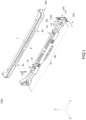
- an electronic apparatus 1000 comprises a transmission dock 100, a first electronic device 200 and a second electronic device 300.
- a transmission dock 100 for connection of the first electronic device 200 and the transmission dock 100 as well as how they are mounted; hence, FIG. 1 shows only part of the first electronic device 200 and the second electronic device 300.
- the first electronic device 200 is a panel computer and has a display portion (not shown).
- the display portion is, for example, a liquid crystal display panel for displaying a frame and executing various touch operations.
- the first electronic device 200 functions independently as a tablet and has therein electronic components, such as a central processing unit (CPU), a hard disk drive (HDD), a random access memory (RAM), and a battery, which operate in conjunction with each other to perform various functions, but the present invention is not limited thereto.
- CPU central processing unit
- HDD hard disk drive
- RAM random access memory
- the second electronic device 300 has a plurality of input components (not shown, whereby a user enters data into the second electronic device 300), including a keyboard, a touch panel and a plurality of keys.
- the first electronic device 200 and the second electronic device 300 come with ports, such as a headphone jack and a USB jack, to meet various fundamental needs, but the present invention is not limited thereto.
- the second electronic device 300 is pivotally connected to one side of the transmission dock 100, whereas a connecting lateral side 201 of the first electronic device 200 is adapted to be inserted in a support direction D1 and received in a receiving slot 110s of the transmission dock 100 so as to be connected to a support surface S1 of the transmission dock 100.
- the support direction D1 is substantially perpendicular to the support surface S1.
- the support surface S1 of the transmission dock 100 is an upper surface attributed to the transmission dock 100 and dedicated to supporting one side of the first electronic device 200.
- a connector (not shown) disposed on the connecting lateral side 201 of the first electronic device 200 is electrically connected to a connector (not shown) disposed on the support surface S1 of the transmission dock 100 to enable exchange of signals and electrical power between the first electronic device 200 and the second electronic device 300.
- signals are sent to the first electronic device 200 from the second electronic device 300 through a keyboard, a touch panel or keys disposed on the second electronic device 300 so that the first electronic device 200 receives the signals and acts in response to the signals.
- the first electronic device 200 and the second electronic device 300 can be demounted and mounted, allowing the electronic apparatus 1000 to form a demountable, mountable two-piece computer.
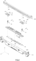
- FIG. 2 is a partial exploded perspective view of the electronic apparatus shown in FIG. 1 .
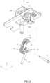
- FIG. 3 is a partial exploded enlarged view of a rotary fastening element and a transmission dock shown in FIG. 1 .
- FIG. 4A is a partial exploded, laterally cross-sectional, enlarged view of the electronic apparatus shown in FIG. 1 .
- FIG. 4B is a partial enlarged view of the electronic apparatus shown in FIG. 4A .
- FIG. 2 shows part of the first electronic device 200 but omits the second electronic device 300, whereas FIG. 4A omits the second electronic device 300.
- the transmission dock 100 comprises a base 110, two rotary fastening elements 10 and two guiding frames 30.
- the base 110 has the support surface S1 which connects with the first electronic device 200 and the receiving slot 110s which receives the connecting lateral side 201 of the first electronic device 200.
- the guiding frames 30, part of the support surface S1, and a pivotal member 101 disposed on each guiding frame 30 are simultaneously formed with an aluminum-magnesium alloy mold. Therefore (in this alternative example), the guiding frames 30, part of the support surface S1, and the pivotal member 101 are integrally formed with a single alloy mold. However, in another embodiment, the pivotal member 101 is integrally formed with the base 110.
- the guiding frames 30 are protrudingly disposed on the support surface S1.
- the guiding frames 30 are each a substantially inverted U-shaped hollow-cored structure.
- the guiding frames 30 each have two opposing outer sidewalls 310 and 320.
- the outer sidewalls 320 of the guiding frames 30 each have an opening 321.
- the rotary fastening elements 10 each comprise a pivotal portion 11, an arm 12, a hook portion 13 and a rod 14.
- the pivotal portion 11 is pivotally connected to the base 110 of the transmission dock 100 about an axis A1 and positioned proximate to a corresponding one of the outer sidewalls 320 of the guiding frames 30. Referring to FIG. 3 , the pivotal portion 11 is placed in the pivotal member 101 beneath the alloy mold for forming the guiding frames 30, and then a shaft 9 is passed through the pivotal member 101 and the pivotal portion 11, thereby allowing the rotary fastening element 10 to be pivotally connected to the alloy mold for forming the guiding frames 30.
- the axis A1 (equivalent to the direction in which the shaft 9 extends) is substantially parallel to the support surface S1 of the transmission dock 100 (from, for example, the angle taken in FIG. 4A .)
- the arm 12 and the hook portion 13 extend from the pivotal portion 11 successively, whereas the rod 14 extends from the pivotal portion 11 in a direction away from the arm 12.
- the rotary fastening elements 10 each further comprise a bump 15 formed at the tip of the hook portion 13.
- the hook portion 13 has a pushed area 131.
- the rotary fastening element 10 rotates about the axis A1 until it reaches an engaging state (shown in FIG. 4B ).
- the hook portion 13 of the rotary fastening element 10 protrudes out of the opening 321 of the outer sidewall 320 of the guiding frames 30, thereby allowing the pushed area 131 to be exposed from the guiding frames 30.
- the first electronic device 200 has two translating frames 40 concavely disposed on the connecting lateral side 201 of the first electronic device 200 and corresponding in position to the guiding frames 30, respectively.
- the translating frames 40 each have two opposing inner sidewalls 410, 420 and two upper wall surfaces 430, 440 which adjoin the two inner sidewalls 410, 420, respectively.
- the electronic apparatus 1000 comprises an engaging mechanism 1.
- the engaging mechanism 1 prevents the first electronic device 200 from separating from the transmission dock 100 and thus disconnecting from the second electronic device 300, when the connecting lateral side 201 of the first electronic device 200 connects with the support surface S1 of the transmission dock 100.
- the engaging mechanism 1 for example, comprises the two rotary fastening elements 10, the two guiding frames 30, the two translating frames 40, a linking element 50, an elastic element 60, an unfastening element 70 and a security knob 80.
- the linking element 50 is slidably disposed at the base 110 of the transmission dock 100.
- the two rods 14 of the rotary fastening elements 10 penetrate the linking element 50 simultaneously; hence, the linking element 50 is adapted to drive the two rods 14 simultaneously.
- the elastic element 60 is a tension spring, with one end fixed to the base 110 of the transmission dock 100, and the other end fixed to the linking element 50. Normally, the elastic element 60 exerts on the linking element 50 a drag in the direction indicated by arrow A; hence, the linking element 50 enables the elastic element 60 to drive the two rotary fastening elements 10 into the engaging state, thereby allowing the pushed area 131 to be exposed from the guiding frames 30.
- the unfastening element 70 is fixed to one side of the linking element 50.
- a user operates the unfastening element 70 in order to drive the linking element 50 to slide relative to the transmission dock 100.
- the unfastening element 70 slidably moves between an unfastening position and a fastening position.
- the elastic element 60 normally pulls the unfastening element 70 toward the fastening position through the linking element 50 in the absence of the user's operation of the unfastening element 70.
- the security knob 80 is disposed inward to the unfastening element 70 and aligned in a direction perpendicular to the direction in which the unfastening element 70 slidably moves.
- the security knob 80 protrudes out of a slide hole 71 of the unfastening element 70 and is adapted to allow the user to use his or her finger to move and switch the security knob 80 between a protruded position and a hidden position.
- FIGs. 5A-6 there are shown in FIGs. 5A-5B schematic views of operation of the electronic apparatus of FIG. 1 and shown in FIG. 6 a partial enlarged view of FIG. 5B .
- FIGs. 5A-6 illustrate how to mount the first electronic device 200 and the second electronic device 300 and thereby clearly depict positions of components of the engaging mechanism 1 relative to each other and operation of the components.
- the user inserts the first electronic device 200 in the support direction D1 into the receiving slot 110s of the transmission dock 100 to allow the first electronic device 200 to connect with the support surface S1 of the transmission dock 100.
- the translating frames 40 move together with the first electronic device 200 in the support direction D1 to fit to the guiding frames 30 on the support surface S1.
- the joint use of the guiding frames 30 and the translating frames 40 enables the user to move the first electronic device 200 in the correct direction required for mounting the first electronic device 200.
- the inner sidewall 420 of the translating frames 40 pushes the pushed area 131 on the hook portion 13 protruding from the outer sidewall 320 of the guiding frames 30, because the hook portion 13 is located on a path of movement of the inner sidewall 420 of the translating frames 40.
- the translating frames 40 keep moving in the support direction D1 to force the hook portion 13 to move into the guiding frames 30 and thus allow the rotary fastening element 10 to turn counterclockwise (from the angle taken in FIG. 5A ), thereby allowing the inner sidewall 420 to slide past the hook portion 13.
- the connecting lateral side 201 connects with the support surface S1
- the translating frames 40 no longer press against the hook portion 13 of the rotary fastening element 10, and in consequence the elastic element 60 pulls the rod 14 of the rotary fastening element 10 in the direction indicated by arrow A through the linking element 50, thereby allowing the rotary fastening element 10 to turn clockwise (from the angle taken in FIG. 5B ) and reach the engaging state.
- FIG. 6 shows that one of the rotary fastening elements 10 ( FIG. 5B ) is in the engaging state.
- the hook portion 13 of the rotary fastening element 10 is engaged with the translating frames 40 and stopped above the upper wall surface 440 of the translating frames 40.
- a reference line R1 parallel to the support direction D1 crosses the hook portion 13, the upper wall surface 440, and the shaft 9 passed through the pivotal portion 11.
- the translating frames 40 tend to move upward (i.e., away from the support direction D1), the force exerted by the upper wall surface 440 on the hook portion 13 of the rotary fastening element 10 does not produce any torque otherwise to be applied to the rotary fastening element 10, because the extension line of the force exerted by the upper wall surface 440 on the hook portion 13 of the rotary fastening element 10 crosses the shaft 9 passed through the pivotal portion 11. Therefore, if the first electronic device 200 tends to move away from the transmission dock 100 in response to a vibration or impact, the rotary fastening element 10 will neither move nor rotate, thereby keeping the first electronic device 200 at a position conducive to its connection with the support surface S1.
- the bump 15 of the rotary fastening element 10 is fastened to the outer side of the translating frames 40 to not only change the direction in which the translating frames 40 exert a force on the hook portion 13 (so as to produce, for example, a torque whereby the rotary fastening element 10 rotates to reach the engaging state), but also increase the friction between the hook portion 13 and the translating frames 40, thereby lowering the chance that the rotary fastening element 10 will quit the engaging state.
- FIG. 7 a partial enlarged view of an unfastening element and a security knob of FIG. 5B
- FIG. 8 a schematic view of a protruded position which a security knob shown in FIG. 5B switches to.
- the unfastening element 70 returns to the fastening position (shown in FIG. 7 ) as the linking element 50 slides, while the elastic element 60 is bringing the rotary fastening element 10 back to the engaging state through the linking element 50.
- the security knob 80 is slided upward and switched to the protruded position.
- the security knob 80 protrudes from the upper edge of the unfastening element 70 and enters a limiting recess 111 of the transmission dock 100.
- the limiting recess 111 prevents the security knob 80 from sliding together with the unfastening element 70 and thereby confines the unfastening element 70 to the fastening position so that the user cannot move the security knob 80, so as to prevent the unfastening element 70 from being inadvertently touched to cause the rotary fastening element 10 to quit the engaging state.
- FIG. 9 a schematic view of an unfastening position which an unfastening element shown in FIG. 5B switches to
- FIG. 10 a schematic view of the unfastening position which the unfastening element shown in FIG. 5B switches to.
- the user slides the security knob 80 downward back to the hidden position (shown in FIG. 7 ) and then pushes the unfastening element 70 toward the unfastening position (in the direction indicated by arrow B) so that the linking element 50 drives to the rotary fastening element 10 to rotate counterclockwise (from the angle taken in FIG. 10 ), and in consequence the rotary fastening element 10 quits the engaging state, thereby terminating the engagement relationship between the hook portion 13 and the translating frames 40.
- the first electronic device 200 can be removed from the transmission dock 100.
- the translating frames 40 of the engaging mechanism 1 each comprise the two inner sidewalls 420, 430 and the two upper wall surfaces 430, 440
- the present invention is not restrictive of the quantity of the aforesaid components.
- the translating frames 40 each comprise an inner sidewall and an upper wall surface which adjoins the inner sidewall.
- the rotary fastening elements 10, the guiding frames 30 and the translating frames 40 of the engaging mechanism 1 are each in the number of two, the present invention is not restrictive of their quantity.
- the engaging mechanism comprises one said rotary fastening element 10, one said guiding frame 30 and one said translating frame 40 and is still able to prevent the first electronic device 200 from moving away from the transmission dock 100 and separating from the transmission dock 100.
- the engaging mechanism 1 comprises the linking element 50 and the elastic element 60.
- the engaging mechanism dispenses with the elastic element 60 but has a torsional spring disposed on each of the two rotary fastening elements 10, thereby being still able to cause the rotary fastening elements 10 to normally reach the engaging state.
- the engaging mechanism can also dispense with the linking element 50, because both the two rotary fastening elements 10 can reach the engaging state.
- the unfastening element 70 and the security knob 80 are optional.
- the engaging mechanism dispenses with the unfastening element 70 and the security knob 80, as the user performs an unfastening process by moving manually the two rotary fastening elements 10 and thereby allowing them to quit the engaging state, simultaneously.
- the user finishes performing the assembly process by moving the first electronic device (i.e., a monitor) in the support direction substantially perpendicular to the support surface so as for the first electronic device to connect with the transmission dock, because the rotary fastening elements rotate about the axis substantially parallel to the support surface of the transmission dock, not to mention that in the aforesaid course the translating frames smoothly push and slide past the rotary fastening elements so as to effectuate engagement.
- the engaging mechanism of the present invention is operated intuitively and conveniently and thus enables the user to mount the first electronic device (i.e., a monitor) on the second electronic device (i.e., a keyboard) quickly.
- the rotary fastening elements are stopped on the upper wall surfaces of the translating frames as soon as the rotary fastening elements rotate and reach the engaging state; hence, the translating frames are restricted by the rotary fastening elements and thus stay on the support surface. Therefore, the first electronic device stays on the support surface to reinforce the connection of the first electronic device and the second electronic device and prevent the first electronic device from moving away from the transmission dock and separating from the transmission dock, thereby precluding termination of the engagement relationship between the first electronic device and the second electronic device because of a vibration or impact.
- the engaging mechanism, the transmission dock equipped with the same, and the electronic apparatus having the same are advantageously conducive to quick assembly of a two-piece computer and firm connection of a tablet and the transmission dock, easy to use, and conducive to a slim chance that the connection will be undermined because of impacts and vibrations.
Landscapes
- Engineering & Computer Science (AREA)
- Theoretical Computer Science (AREA)
- Computer Hardware Design (AREA)
- Physics & Mathematics (AREA)
- Human Computer Interaction (AREA)
- General Engineering & Computer Science (AREA)
- General Physics & Mathematics (AREA)
- Signal Processing (AREA)
- Mathematical Physics (AREA)
- Casings For Electric Apparatus (AREA)
Claims (6)
- Mécanisme d'enclenchement (1), comprenant :au moins un élément de fixation rotatif (10) tournant autour d'un axe (A1) pour atteindre un état d'enclenchement ;au moins un cadre de guidage (30) comportant deux parois latérales extérieures (310, 320) opposées et disposé en saillie sur une surface de support (S1) d'un socle de transmission (100), l'axe (A1) étant sensiblement parallèle à la surface de support (S1) et l'au moins un élément de fixation rotatif (10) faisant saillie par rapport à l'une des deux parois latérales extérieures (310, 320) dans l'état d'enclenchement ; etau moins un cadre de translation (40) comportant deux parois latérales intérieures (410, 420) opposées et deux surfaces de paroi supérieure (430, 440) adjacentes respectivement aux deux parois intérieures (410, 420), si bien que lorsque l'au moins un cadre de translation (40) se raccorde à la surface de support (S1), les deux parois latérales extérieures (310, 320) sont disposées entre les deux parois latérales intérieures (410, 420), et l'au moins un élément de fixation rotatif (10) tourne et atteint l'état d'enclenchement pour arrêter ainsi l'une des deux surfaces de paroi supérieure (430, 440),l'au moins un élément de fixation rotatif (10) comprenant une partie pivotante (11), un bras (12), une partie crochet (13) et une tige (14), la partie pivotante (11) étant positionnée à proximité d'un côté de l'au moins un cadre de guidage (30) à travers l'axe (A1), ce qui permet au bras (12) et à la partie crochet (13) de s'étendre successivement à partir de la partie pivotante (11), la partie crochet (13) faisant saillie par rapport à l'une des deux parois latérales extérieures (310, 320) et s'arrêtant au niveau de l'une des deux surfaces de paroi supérieure (430, 440) lorsque l'au moins un cadre de translation (40) se raccorde à la surface de support (S1) et que l'au moins un élément de fixation rotatif (10) est dans l'état d'enclenchement,le mécanisme d'enclenchement (1) comprenant en outre un élément de liaison (50) et un élément élastique (60), l'élément de liaison (50) se raccordant aux deux éléments de fixation rotatifs (10) et l'élément élastique (60) se raccordant à l'élément de liaison (50), ce qui permet aux deux éléments de fixation rotatifs (10) d'atteindre normalement l'état d'enclenchement ; etl'une des deux parois latérales intérieures (410, 420) poussant une zone poussée (131) de la partie crochet (13) et amenant l'au moins un élément de fixation rotatif (10) à tourner dans le sens anti-horaire et à quitter l'état d'enclenchement tandis que l'au moins un cadre de translation (40) se déplace dans une direction de support (D1) sensiblement perpendiculaire à la surface de support (S1) de manière à se raccorder à la surface de support (S1) ;lorsque le côté latéral de raccordement (201) se raccorde à la surface de support (S1), les cadres de translation (40) n'appuyant plus sur la partie crochet (13) de l'élément de fixation rotatif (10) et, en conséquence, l'élément élastique (60) tirant la tige (14) de l'élément de fixation rotatif (10) dans une direction passant par l'élément de liaison (50), ce qui permet à l'élément de fixation rotatif (10) de tourner dans le sens horaire et d'atteindre l'état d'enclenchement.
- Mécanisme d'enclenchement (1) selon la revendication 1, dans lequel une ligne de référence (R1) parallèle à la direction de support (D1) traverse la partie crochet (13), l'une des deux surfaces de paroi supérieure (430, 440) et la partie pivotante (11) lorsque l'au moins un cadre de translation (40) se raccorde à la surface de support (S1) et que l'au moins un élément de fixation rotatif (10) est dans l'état d'enclenchement.
- Socle de transmission (100), conçu pour se raccorder à un premier dispositif électronique (200), ce qui permet à un côté latéral de raccordement (201) du premier dispositif électronique (200) de s'aligner sur une direction de support (D1) et de se raccorder au socle de transmission (100) par l'intermédiaire d'au moins un cadre de translation (40), le socle de transmission (100) comprenant :
un mécanisme d'enclenchement selon la revendication 1, conçu pour permettre de fixer le premier dispositif électronique (200) au socle de transmission (100). - Socle de transmission (100) selon la revendication 3, dans lequel une ligne de référence (R1) parallèle à la direction de support (D1) traverse la partie crochet (13), l'une des deux surfaces de paroi supérieure (430, 440) et la partie pivotante (11) lorsque l'au moins un cadre de translation (40) se raccorde à la surface de support (S1) et que l'au moins un élément de fixation rotatif (10) est dans l'état d'enclenchement.
- Appareil électronique (1000), comprenant :un socle de transmission (100) ;un premier dispositif électronique (200) comportant un côté latéral de raccordement (201) et au moins un cadre de translation (40), l'au moins un cadre de translation (40) étant disposé sur le côté latéral de raccordement (201), ce qui permet au premier dispositif électronique (200) d'être aligné sur une direction de support (D1) et d'être connecté électriquement au socle de transmission (100) ;un second dispositif électronique (300) pour tenir le socle de transmission (100), le socle de transmission (100) comprenant :
un mécanisme d'enclenchement selon la revendication 1, conçu pour permettre de fixer le premier dispositif électronique (200) au socle de transmission (100). - Appareil électronique selon la revendication 5, dans lequel une ligne de référence (R1) parallèle à la direction de support (D1) traverse la partie crochet (13), l'une des deux surfaces de paroi supérieure (430, 440) et la partie pivotante (11) lorsque l'au moins un cadre de translation (40) se raccorde à la surface de support (S1) et que l'au moins un élément de fixation rotatif (10) est dans l'état d'enclenchement.
Priority Applications (1)
| Application Number | Priority Date | Filing Date | Title |
|---|---|---|---|
| EP17195413.4A EP3467613B1 (fr) | 2017-10-09 | 2017-10-09 | Mécanisme d'engagement, dock de transmission en étant équipé et appareil électronique comprenant ce dernier |
Applications Claiming Priority (1)
| Application Number | Priority Date | Filing Date | Title |
|---|---|---|---|
| EP17195413.4A EP3467613B1 (fr) | 2017-10-09 | 2017-10-09 | Mécanisme d'engagement, dock de transmission en étant équipé et appareil électronique comprenant ce dernier |
Publications (2)
| Publication Number | Publication Date |
|---|---|
| EP3467613A1 EP3467613A1 (fr) | 2019-04-10 |
| EP3467613B1 true EP3467613B1 (fr) | 2024-10-30 |
Family
ID=60143505
Family Applications (1)
| Application Number | Title | Priority Date | Filing Date |
|---|---|---|---|
| EP17195413.4A Active EP3467613B1 (fr) | 2017-10-09 | 2017-10-09 | Mécanisme d'engagement, dock de transmission en étant équipé et appareil électronique comprenant ce dernier |
Country Status (1)
| Country | Link |
|---|---|
| EP (1) | EP3467613B1 (fr) |
Families Citing this family (1)
| Publication number | Priority date | Publication date | Assignee | Title |
|---|---|---|---|---|
| EP4341765A1 (fr) | 2021-07-14 | 2024-03-27 | Huawei Technologies Co., Ltd. | Agencement de connexion détachable pour connecter des dispositifs électroniques |
Family Cites Families (4)
| Publication number | Priority date | Publication date | Assignee | Title |
|---|---|---|---|---|
| CN101153525B (zh) * | 2006-09-30 | 2013-01-09 | Ge医疗系统环球技术有限公司 | 连接/断开机构及组合装置 |
| JP5406751B2 (ja) * | 2010-02-04 | 2014-02-05 | パナソニック株式会社 | 盗難防止装置 |
| US20140133080A1 (en) * | 2012-11-15 | 2014-05-15 | Samsung Electronics Co., Ltd. | Detachable electronic device and connection apparatus usable with the same |
| JPWO2016103579A1 (ja) * | 2014-12-26 | 2017-11-02 | パナソニックIpマネジメント株式会社 | 電子機器 |
-
2017
- 2017-10-09 EP EP17195413.4A patent/EP3467613B1/fr active Active
Also Published As
| Publication number | Publication date |
|---|---|
| EP3467613A1 (fr) | 2019-04-10 |
Similar Documents
| Publication | Publication Date | Title |
|---|---|---|
| US10437291B2 (en) | Engaging mechanism, transmission dock equipped with the same, and electronic apparatus having the same | |
| US7974088B2 (en) | Retaining apparatus for data storage device | |
| US6480374B1 (en) | Vertically disposed notebook computer | |
| US8199476B2 (en) | Notebook computer | |
| CN102005235B (zh) | 数据存储器固定装置 | |
| US8576558B2 (en) | Mounting apparatus with rotating member for retaining and buffering data storage device | |
| US9541968B2 (en) | Housing having fixing mechanism | |
| CN101470486B (zh) | 扩展卡锁固装置 | |
| US9462721B2 (en) | Server | |
| US20060256516A1 (en) | Portable computer with detachable display | |
| TWI715430B (zh) | 利用槓桿作動退出抽取式模組之電子裝置及其相關的槓桿機構 | |
| US7428145B2 (en) | Electronic apparatus | |
| US9298271B2 (en) | Mounting device and electronic apparatus | |
| US7408771B2 (en) | Mounting device for data storage device | |
| US20140153166A1 (en) | Electronic apparatus and detachable assembly thereof | |
| US6805505B2 (en) | Keyboard and computer system allowing for simple keyboard removal | |
| US11622463B2 (en) | Chassis and cage thereof | |
| US7681210B2 (en) | Ejection apparatus for data storage device | |
| KR20020057436A (ko) | 휴대용컴퓨터 | |
| US7724510B2 (en) | Electronic apparatus and assembly | |
| EP3467613B1 (fr) | Mécanisme d'engagement, dock de transmission en étant équipé et appareil électronique comprenant ce dernier | |
| US20120063067A1 (en) | Panel fixing mechanism and displaying device thereof | |
| US20070047197A1 (en) | Electronic apparatus | |
| WO2022111656A1 (fr) | Dispositif électronique détachable | |
| US7147484B1 (en) | Electronic apparatus and board assembly |
Legal Events
| Date | Code | Title | Description |
|---|---|---|---|
| PUAI | Public reference made under article 153(3) epc to a published international application that has entered the european phase |
Free format text: ORIGINAL CODE: 0009012 |
|
| STAA | Information on the status of an ep patent application or granted ep patent |
Free format text: STATUS: REQUEST FOR EXAMINATION WAS MADE |
|
| 17P | Request for examination filed |
Effective date: 20190301 |
|
| AK | Designated contracting states |
Kind code of ref document: A1 Designated state(s): AL AT BE BG CH CY CZ DE DK EE ES FI FR GB GR HR HU IE IS IT LI LT LU LV MC MK MT NL NO PL PT RO RS SE SI SK SM TR |
|
| AX | Request for extension of the european patent |
Extension state: BA ME |
|
| STAA | Information on the status of an ep patent application or granted ep patent |
Free format text: STATUS: EXAMINATION IS IN PROGRESS |
|
| 17Q | First examination report despatched |
Effective date: 20201216 |
|
| RAP3 | Party data changed (applicant data changed or rights of an application transferred) |
Owner name: GETAC HOLDINGS CORPORATION |
|
| RAP3 | Party data changed (applicant data changed or rights of an application transferred) |
Owner name: GETAC HOLDINGS CORPORATION |
|
| GRAP | Despatch of communication of intention to grant a patent |
Free format text: ORIGINAL CODE: EPIDOSNIGR1 |
|
| STAA | Information on the status of an ep patent application or granted ep patent |
Free format text: STATUS: GRANT OF PATENT IS INTENDED |
|
| INTG | Intention to grant announced |
Effective date: 20240716 |
|
| GRAS | Grant fee paid |
Free format text: ORIGINAL CODE: EPIDOSNIGR3 |
|
| GRAA | (expected) grant |
Free format text: ORIGINAL CODE: 0009210 |
|
| STAA | Information on the status of an ep patent application or granted ep patent |
Free format text: STATUS: THE PATENT HAS BEEN GRANTED |
|
| AK | Designated contracting states |
Kind code of ref document: B1 Designated state(s): AL AT BE BG CH CY CZ DE DK EE ES FI FR GB GR HR HU IE IS IT LI LT LU LV MC MK MT NL NO PL PT RO RS SE SI SK SM TR |
|
| REG | Reference to a national code |
Ref country code: GB Ref legal event code: FG4D |
|
| REG | Reference to a national code |
Ref country code: CH Ref legal event code: EP |
|
| REG | Reference to a national code |
Ref country code: DE Ref legal event code: R096 Ref document number: 602017085755 Country of ref document: DE |
|
| REG | Reference to a national code |
Ref country code: IE Ref legal event code: FG4D |
|
| REG | Reference to a national code |
Ref country code: LT Ref legal event code: MG9D |
|
| REG | Reference to a national code |
Ref country code: NL Ref legal event code: MP Effective date: 20241030 |
|
| PG25 | Lapsed in a contracting state [announced via postgrant information from national office to epo] |
Ref country code: HR Free format text: LAPSE BECAUSE OF FAILURE TO SUBMIT A TRANSLATION OF THE DESCRIPTION OR TO PAY THE FEE WITHIN THE PRESCRIBED TIME-LIMIT Effective date: 20241030 Ref country code: PT Free format text: LAPSE BECAUSE OF FAILURE TO SUBMIT A TRANSLATION OF THE DESCRIPTION OR TO PAY THE FEE WITHIN THE PRESCRIBED TIME-LIMIT Effective date: 20250228 Ref country code: IS Free format text: LAPSE BECAUSE OF FAILURE TO SUBMIT A TRANSLATION OF THE DESCRIPTION OR TO PAY THE FEE WITHIN THE PRESCRIBED TIME-LIMIT Effective date: 20250228 |
|
| PG25 | Lapsed in a contracting state [announced via postgrant information from national office to epo] |
Ref country code: FI Free format text: LAPSE BECAUSE OF FAILURE TO SUBMIT A TRANSLATION OF THE DESCRIPTION OR TO PAY THE FEE WITHIN THE PRESCRIBED TIME-LIMIT Effective date: 20241030 Ref country code: NL Free format text: LAPSE BECAUSE OF FAILURE TO SUBMIT A TRANSLATION OF THE DESCRIPTION OR TO PAY THE FEE WITHIN THE PRESCRIBED TIME-LIMIT Effective date: 20241030 |
|
| REG | Reference to a national code |
Ref country code: AT Ref legal event code: MK05 Ref document number: 1737518 Country of ref document: AT Kind code of ref document: T Effective date: 20241030 |
|
| PG25 | Lapsed in a contracting state [announced via postgrant information from national office to epo] |
Ref country code: BG Free format text: LAPSE BECAUSE OF FAILURE TO SUBMIT A TRANSLATION OF THE DESCRIPTION OR TO PAY THE FEE WITHIN THE PRESCRIBED TIME-LIMIT Effective date: 20241030 |
|
| PG25 | Lapsed in a contracting state [announced via postgrant information from national office to epo] |
Ref country code: ES Free format text: LAPSE BECAUSE OF FAILURE TO SUBMIT A TRANSLATION OF THE DESCRIPTION OR TO PAY THE FEE WITHIN THE PRESCRIBED TIME-LIMIT Effective date: 20241030 |
|
| PG25 | Lapsed in a contracting state [announced via postgrant information from national office to epo] |
Ref country code: NO Free format text: LAPSE BECAUSE OF FAILURE TO SUBMIT A TRANSLATION OF THE DESCRIPTION OR TO PAY THE FEE WITHIN THE PRESCRIBED TIME-LIMIT Effective date: 20250130 |
|
| PG25 | Lapsed in a contracting state [announced via postgrant information from national office to epo] |
Ref country code: LV Free format text: LAPSE BECAUSE OF FAILURE TO SUBMIT A TRANSLATION OF THE DESCRIPTION OR TO PAY THE FEE WITHIN THE PRESCRIBED TIME-LIMIT Effective date: 20241030 Ref country code: GR Free format text: LAPSE BECAUSE OF FAILURE TO SUBMIT A TRANSLATION OF THE DESCRIPTION OR TO PAY THE FEE WITHIN THE PRESCRIBED TIME-LIMIT Effective date: 20250131 Ref country code: AT Free format text: LAPSE BECAUSE OF FAILURE TO SUBMIT A TRANSLATION OF THE DESCRIPTION OR TO PAY THE FEE WITHIN THE PRESCRIBED TIME-LIMIT Effective date: 20241030 |
|
| PG25 | Lapsed in a contracting state [announced via postgrant information from national office to epo] |
Ref country code: PL Free format text: LAPSE BECAUSE OF FAILURE TO SUBMIT A TRANSLATION OF THE DESCRIPTION OR TO PAY THE FEE WITHIN THE PRESCRIBED TIME-LIMIT Effective date: 20241030 |
|
| PG25 | Lapsed in a contracting state [announced via postgrant information from national office to epo] |
Ref country code: RS Free format text: LAPSE BECAUSE OF FAILURE TO SUBMIT A TRANSLATION OF THE DESCRIPTION OR TO PAY THE FEE WITHIN THE PRESCRIBED TIME-LIMIT Effective date: 20250130 |
|
| PG25 | Lapsed in a contracting state [announced via postgrant information from national office to epo] |
Ref country code: SM Free format text: LAPSE BECAUSE OF FAILURE TO SUBMIT A TRANSLATION OF THE DESCRIPTION OR TO PAY THE FEE WITHIN THE PRESCRIBED TIME-LIMIT Effective date: 20241030 |
|
| PG25 | Lapsed in a contracting state [announced via postgrant information from national office to epo] |
Ref country code: DK Free format text: LAPSE BECAUSE OF FAILURE TO SUBMIT A TRANSLATION OF THE DESCRIPTION OR TO PAY THE FEE WITHIN THE PRESCRIBED TIME-LIMIT Effective date: 20241030 |
|
| PG25 | Lapsed in a contracting state [announced via postgrant information from national office to epo] |
Ref country code: EE Free format text: LAPSE BECAUSE OF FAILURE TO SUBMIT A TRANSLATION OF THE DESCRIPTION OR TO PAY THE FEE WITHIN THE PRESCRIBED TIME-LIMIT Effective date: 20241030 |
|
| PG25 | Lapsed in a contracting state [announced via postgrant information from national office to epo] |
Ref country code: RO Free format text: LAPSE BECAUSE OF FAILURE TO SUBMIT A TRANSLATION OF THE DESCRIPTION OR TO PAY THE FEE WITHIN THE PRESCRIBED TIME-LIMIT Effective date: 20241030 |
|
| PG25 | Lapsed in a contracting state [announced via postgrant information from national office to epo] |
Ref country code: SK Free format text: LAPSE BECAUSE OF FAILURE TO SUBMIT A TRANSLATION OF THE DESCRIPTION OR TO PAY THE FEE WITHIN THE PRESCRIBED TIME-LIMIT Effective date: 20241030 |
|
| PG25 | Lapsed in a contracting state [announced via postgrant information from national office to epo] |
Ref country code: CZ Free format text: LAPSE BECAUSE OF FAILURE TO SUBMIT A TRANSLATION OF THE DESCRIPTION OR TO PAY THE FEE WITHIN THE PRESCRIBED TIME-LIMIT Effective date: 20241030 |
|
| REG | Reference to a national code |
Ref country code: DE Ref legal event code: R097 Ref document number: 602017085755 Country of ref document: DE |
|
| PLBE | No opposition filed within time limit |
Free format text: ORIGINAL CODE: 0009261 |
|
| STAA | Information on the status of an ep patent application or granted ep patent |
Free format text: STATUS: NO OPPOSITION FILED WITHIN TIME LIMIT |
|
| PG25 | Lapsed in a contracting state [announced via postgrant information from national office to epo] |
Ref country code: SE Free format text: LAPSE BECAUSE OF FAILURE TO SUBMIT A TRANSLATION OF THE DESCRIPTION OR TO PAY THE FEE WITHIN THE PRESCRIBED TIME-LIMIT Effective date: 20241030 |
|
| 26N | No opposition filed |
Effective date: 20250731 |
|
| PGFP | Annual fee paid to national office [announced via postgrant information from national office to epo] |
Ref country code: DE Payment date: 20251002 Year of fee payment: 9 |
|
| PGFP | Annual fee paid to national office [announced via postgrant information from national office to epo] |
Ref country code: GB Payment date: 20251001 Year of fee payment: 9 |
|
| PGFP | Annual fee paid to national office [announced via postgrant information from national office to epo] |
Ref country code: IT Payment date: 20251021 Year of fee payment: 9 |
|
| PGFP | Annual fee paid to national office [announced via postgrant information from national office to epo] |
Ref country code: FR Payment date: 20251001 Year of fee payment: 9 |