EP3470300A1 - Hydraulische lenkeinrichtung - Google Patents
Hydraulische lenkeinrichtung Download PDFInfo
- Publication number
- EP3470300A1 EP3470300A1 EP18192750.0A EP18192750A EP3470300A1 EP 3470300 A1 EP3470300 A1 EP 3470300A1 EP 18192750 A EP18192750 A EP 18192750A EP 3470300 A1 EP3470300 A1 EP 3470300A1
- Authority
- EP
- European Patent Office
- Prior art keywords
- valve
- steering
- cylinder
- flow control
- connection
- Prior art date
- Legal status (The legal status is an assumption and is not a legal conclusion. Google has not performed a legal analysis and makes no representation as to the accuracy of the status listed.)
- Granted
Links
Images
Classifications
-
- B—PERFORMING OPERATIONS; TRANSPORTING
- B62—LAND VEHICLES FOR TRAVELLING OTHERWISE THAN ON RAILS
- B62D—MOTOR VEHICLES; TRAILERS
- B62D1/00—Steering controls, i.e. means for initiating a change of direction of the vehicle
- B62D1/02—Steering controls, i.e. means for initiating a change of direction of the vehicle vehicle-mounted
- B62D1/22—Alternative steering-control elements, e.g. for teaching purposes
-
- B—PERFORMING OPERATIONS; TRANSPORTING
- B62—LAND VEHICLES FOR TRAVELLING OTHERWISE THAN ON RAILS
- B62D—MOTOR VEHICLES; TRAILERS
- B62D5/00—Power-assisted or power-driven steering
- B62D5/06—Power-assisted or power-driven steering fluid, i.e. using a pressurised fluid for most or all the force required for steering a vehicle
- B62D5/09—Power-assisted or power-driven steering fluid, i.e. using a pressurised fluid for most or all the force required for steering a vehicle characterised by means for actuating valves
- B62D5/093—Telemotor driven by steering wheel movement
-
- B—PERFORMING OPERATIONS; TRANSPORTING
- B62—LAND VEHICLES FOR TRAVELLING OTHERWISE THAN ON RAILS
- B62D—MOTOR VEHICLES; TRAILERS
- B62D5/00—Power-assisted or power-driven steering
- B62D5/06—Power-assisted or power-driven steering fluid, i.e. using a pressurised fluid for most or all the force required for steering a vehicle
- B62D5/30—Safety devices, e.g. alternate emergency power supply or transmission means to ensure steering upon failure of the primary steering means
-
- B—PERFORMING OPERATIONS; TRANSPORTING
- B62—LAND VEHICLES FOR TRAVELLING OTHERWISE THAN ON RAILS
- B62D—MOTOR VEHICLES; TRAILERS
- B62D5/00—Power-assisted or power-driven steering
- B62D5/06—Power-assisted or power-driven steering fluid, i.e. using a pressurised fluid for most or all the force required for steering a vehicle
- B62D5/07—Supply of pressurised fluid for steering also supplying other consumers ; control thereof
-
- B—PERFORMING OPERATIONS; TRANSPORTING
- B62—LAND VEHICLES FOR TRAVELLING OTHERWISE THAN ON RAILS
- B62D—MOTOR VEHICLES; TRAILERS
- B62D5/00—Power-assisted or power-driven steering
- B62D5/06—Power-assisted or power-driven steering fluid, i.e. using a pressurised fluid for most or all the force required for steering a vehicle
- B62D5/09—Power-assisted or power-driven steering fluid, i.e. using a pressurised fluid for most or all the force required for steering a vehicle characterised by means for actuating valves
-
- B—PERFORMING OPERATIONS; TRANSPORTING
- B62—LAND VEHICLES FOR TRAVELLING OTHERWISE THAN ON RAILS
- B62D—MOTOR VEHICLES; TRAILERS
- B62D5/00—Power-assisted or power-driven steering
- B62D5/06—Power-assisted or power-driven steering fluid, i.e. using a pressurised fluid for most or all the force required for steering a vehicle
- B62D5/09—Power-assisted or power-driven steering fluid, i.e. using a pressurised fluid for most or all the force required for steering a vehicle characterised by means for actuating valves
- B62D5/091—Hydraulic steer-by-wire systems, e.g. the valve being actuated by an electric motor
-
- B—PERFORMING OPERATIONS; TRANSPORTING
- B62—LAND VEHICLES FOR TRAVELLING OTHERWISE THAN ON RAILS
- B62D—MOTOR VEHICLES; TRAILERS
- B62D5/00—Power-assisted or power-driven steering
- B62D5/06—Power-assisted or power-driven steering fluid, i.e. using a pressurised fluid for most or all the force required for steering a vehicle
- B62D5/30—Safety devices, e.g. alternate emergency power supply or transmission means to ensure steering upon failure of the primary steering means
- B62D5/32—Safety devices, e.g. alternate emergency power supply or transmission means to ensure steering upon failure of the primary steering means for telemotor systems
-
- F—MECHANICAL ENGINEERING; LIGHTING; HEATING; WEAPONS; BLASTING
- F15—FLUID-PRESSURE ACTUATORS; HYDRAULICS OR PNEUMATICS IN GENERAL
- F15B—SYSTEMS ACTING BY MEANS OF FLUIDS IN GENERAL; FLUID-PRESSURE ACTUATORS, e.g. SERVOMOTORS; DETAILS OF FLUID-PRESSURE SYSTEMS, NOT OTHERWISE PROVIDED FOR
- F15B11/00—Servomotor systems without provision for follow-up action; Circuits therefor
- F15B11/08—Servomotor systems without provision for follow-up action; Circuits therefor with only one servomotor
-
- F—MECHANICAL ENGINEERING; LIGHTING; HEATING; WEAPONS; BLASTING
- F15—FLUID-PRESSURE ACTUATORS; HYDRAULICS OR PNEUMATICS IN GENERAL
- F15B—SYSTEMS ACTING BY MEANS OF FLUIDS IN GENERAL; FLUID-PRESSURE ACTUATORS, e.g. SERVOMOTORS; DETAILS OF FLUID-PRESSURE SYSTEMS, NOT OTHERWISE PROVIDED FOR
- F15B13/00—Details of servomotor systems ; Valves for servomotor systems
- F15B13/02—Fluid distribution or supply devices characterised by their adaptation to the control of servomotors
- F15B13/04—Fluid distribution or supply devices characterised by their adaptation to the control of servomotors for use with a single servomotor
- F15B13/0401—Valve members; Fluid interconnections therefor
-
- B—PERFORMING OPERATIONS; TRANSPORTING
- B62—LAND VEHICLES FOR TRAVELLING OTHERWISE THAN ON RAILS
- B62D—MOTOR VEHICLES; TRAILERS
- B62D5/00—Power-assisted or power-driven steering
- B62D5/06—Power-assisted or power-driven steering fluid, i.e. using a pressurised fluid for most or all the force required for steering a vehicle
- B62D5/10—Power-assisted or power-driven steering fluid, i.e. using a pressurised fluid for most or all the force required for steering a vehicle characterised by type of power unit
- B62D5/12—Piston and cylinder
Definitions
- the invention relates to a hydraulic steering device.
- Hydraulic steering devices for example in the vehicle sector, are fundamentally familiar to the person skilled in the art. Such a hydraulic steering device is in the generic DE 10 2015 121 328 B3 described.
- the core component of such hydraulic steering devices is a steering cylinder, which is hydraulically connected to a supply system.
- the supply system is hydraulically operatively connected to the steering cylinder via a steering unit in the sense of a main current connection.
- the steering cylinder can be controlled for example via a hand steering wheel.
- the supply system is hydraulically actively connected to the steering cylinder via a flow control valve arrangement, past the main flow connection.
- the flow control valve arrangement can comprise a plurality of independently controllable valves with which forward and return flows to working chambers of the steering cylinder can be adjusted.
- the valves can be controlled as known to realize a steering function.
- the invention has for its object to provide a generic hydraulic steering device in which can reduce pressure losses.
- this object is achieved by a hydraulic steering device with the features mentioned in claim 1.
- This has the advantage that a hydraulic conveyor of the supply system does not have to work against a pressure. In particular, in the case when there is no steering request to the hydraulic steering device, a compensation of the load pressure can take place.
- the release and shut-off valve is in the closed position and the valves of the flow control valve assembly which are connected to a return port of the steering device, are in the open position.
- This can be done in a particularly simple manner, a compensation of the load pressure.
- the cylinder clamping of the steering cylinder according to the currently selected steering position is maintained and the flow control valve assembly is simultaneously relieved.
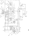
- FIG. 1 shows a schematic representation of a hydraulic steering device.
- the hydraulic steering device 10 comprises a steering valve 12 with a rotary slide-controlled metering pump 14, which is connected via a steering linkage 16 with a hand steering wheel 18.
- the steering device 10 has an inlet port 20, which is connected to a first input 22 of the steering valve 12.
- the steering device 10 also has a return port 24, which is connected to a drain 26 of the steering valve 12.
- the supply system 28 includes a Supply pump 30, which is connected via a flow control valve 32 to the inlet port 20. Further, a tank 34 is provided, which is connected to the return port 24.
- the flow control valve 32 forms a priority valve, by means of which a supply operation of the supply pump 30 between a working hydraulics 36 and the steering device 10 can be controlled.
- the flow control valve 32 receives a signal when requested by the hydraulic steering device 10, which assigns priority to the hydraulic steering device 10 before the working hydraulics 36.
- the steering device 10 also has cylinder ports 40 and 42.
- the cylinder port 40 is connected via a line 44 and the cylinder port 42 via a line 46 to the steering valve 12.
- a steering cylinder 48 is connected, which is connected in a manner not shown with steerable wheels 49 of a vehicle.
- the terminal 40 is connected to a left for the steering direction and the terminal 42 with a responsible for the steering direction chamber of the steering cylinder 48.
- the steering device 10 further includes a flow control valve assembly 50.
- the flow control valve arrangement 50 has a first valve group 52 and a second valve group 54 and a release shut-off valve 56.
- the valve group 52 comprises a valve 58 designed as an inlet valve and a valve 60 designed as a return valve.
- the valve group 54 comprises a valve 62 designed as an inlet valve and a valve formed as a return valve valve 64.
- the valves 58, 60, 62 and 64 are each formed as a person skilled in proportional valves. In such proportional valves, a control piston is held by a compression spring in an initial position and locks the volume flow when the magnet is not actuated. Due to the excitation of the magnet, the control piston is adjusted directly - in proportion to the electrical input signal.
- the valves 58 and 60 are connected to the cylinder port 40 and the valves 62 and 64 connected to the cylinder port 42 via the release valve 56, or connectable.
- the flow control valve assembly 50 further includes a shuttle valve 68 which is connected via load signal lines 65 and 66 to the drain of the valves 58 and 62.
- the Shuttle valve 68 is also connected via a load signal line 67 with a copying valve 69. The pressure signal at the outlet of the valves 58 and 62 can thereby be transmitted to the copying valve 69 and via the control line 38 to the supply pump 30.
- the steering cylinder 48 is thus hydraulically operatively connected via the steering valve 12 to the supply system 28 via a main current connection and via the flow control valve arrangement 50 via a bypass connection bypassing the main flow connection.
- To control the designed as proportional valves 58, 60, 62 and 64 and the release valve 56 are connected via control lines, not shown, with a control unit 70.
- the cylinder port 40 is connected to the valves 58 and 60 and the cylinder port 42 to the valves 62 and 64.
- the control unit 70 evaluates the signals supplied by transducers 82 and 80, which correspond to the desired steering direction, and provides corresponding control signals via the control lines for the valves 58, 60, 62 and 64, respectively.
- a left-hand steering or right-hand steering is carried out via the control unit 70, either the valve 58 and the valve 64 in left-hand drive or the valve 60 and the valve 62 is controlled in the right-hand drive.
- the release valve 56 is closed.
- the valves 60 and 64 are opened.
- the valves 58, 60, 62 and 64 and the load signal lines 65, 66 and 67 to the shuttle valve 68 and the copy valve 69 are thus relieved. Since the pump 30 no longer has to work against the clamped in the cylinders pressure of for example 30 bar, pressure losses can be reduced become. Because of the low pressure losses from the inlet port 20 to the valves 58 and 62, it is possible to increase the flow rate of oil through these valves, for example, to 60 l / min. The steering assistance can be improved hereby.
Landscapes
- Engineering & Computer Science (AREA)
- Mechanical Engineering (AREA)
- Chemical & Material Sciences (AREA)
- Combustion & Propulsion (AREA)
- Transportation (AREA)
- Physics & Mathematics (AREA)
- Fluid Mechanics (AREA)
- General Engineering & Computer Science (AREA)
- Power Steering Mechanism (AREA)
Abstract
Description
- Die Erfindung betrifft eine hydraulische Lenkeinrichtung.
- Hydraulische Lenkeinrichtungen, beispielsweise im Fahrzeugbereich, sind dem Fachmann grundlegend bekannt. Eine solche hydraulische Lenkeinrichtung wird in der gattungsbildenden
DE 10 2015 121 328 B3 beschrieben. - Kernbestandteil derartiger hydraulischer Lenkeinrichtungen ist ein Lenkzylinder, der mit einer Versorgungsanlage hydraulisch verbunden ist. Die Versorgungsanlage ist dabei mit dem Lenkzylinder über ein Lenkaggregat im Sinne einer Hauptstromverbindung hydraulisch wirkverbindbar. Über das Lenkaggregat kann der Lenkzylinder beispielsweise über ein Handlenkrad angesteuert werden. Ferner ist bei hydraulischen Lenkeinrichtungen bekannt, zur mechanisierten oder automatischen Ansteuerung des Lenkzylinders eine Nebenstromverbindung auszubilden. Die Versorgungsanlage wird hierzu mit dem Lenkzylinder über eine Stromregelventilanordnung, vorbei an der Hauptstromverbindung, flexibel hydraulisch wirkverbunden. Die Stromregelventilanordnung kann hierzu mehrere unabhängig ansteuerbare Ventile umfassen, mit denen Vor- und Rückläufe zu Arbeitskammern des Lenkzylinders eingestellt werden können. Über ein Steuergerät mit einer Lenkungssoftware können die Ventile bekannterweise zur Realisierung einer Lenkungsfunktion angesteuert werden.
- Es ist ferner bekannt, der Stromregelventilanordnung ein Freigabe- und Abschaltventil zuzuordnen. Dieses Freigabe- und Abschaltventil ist im Stand der Technik zwischen der Stromregelventilanordnung und der Versorgungsanlage geschaltet.
- Der Erfindung liegt die Aufgabe zugrunde, eine gattungsgemäße hydraulische Lenkeinrichtung zu schaffen, bei der sich Druckverluste reduzieren lassen.
- Erfindungsgemäß wird diese Aufgabe durch eine hydraulische Lenkeinrichtung mit den in Anspruch 1 genannten Merkmalen gelöst. Dadurch, dass das Freigabe- und Abschaltventil zwischen der Stromregelventilanordnung und dem Lenkzylinder geschaltet ist, ist vorteilhaft möglich, Druckverluste an der hydraulischen Lenkeinrichtung zu reduzieren. Dies hat den Vorteil, dass eine hydraulische Fördereinrichtung der Versorgungsanlage nicht gegen einen Druck arbeiten muss. Insbesondere in dem Fall, wenn keine Lenkanforderung an die hydraulische Lenkeinrichtung besteht, kann eine Kompensation des Lastdruckes erfolgen.
- In bevorzugter Ausgestaltung der Erfindung ist hierzu vorgesehen, dass bei nicht angeforderter Lenkbewegung das Freigabe- und Abschaltventil in Schließstellung ist und die Ventile der Stromregelventilanordnung die mit einem Rücklaufanschluss der Lenkeinrichtung verbunden sind, in Offenstellung sind. Hierdurch kann in besonders einfacher Weise eine Kompensation des Lastdruckes erfolgen. Die Zylindereinspannung des Lenkzylinders entsprechend der gerade gewählten Lenkstellung bleibt beibehalten und die Stromregelventilanordnung wird gleichzeitig entlastet.
- Hierdurch wird weiterhin vorteilhaft möglich, die Ventile der Stromregelventilanordnung so zu optimieren, dass diese hinsichtlich eines größeren Durchflusses ausgelegt werden können. Dadurch, dass die internen Druckverluste in der hydraulischen Lenkeinrichtung reduziert sind, kann diese größere Ölmenge bereitgestellt werden.
- Weitere bevorzugte Ausgestaltungen der Erfindung ergeben sich aus den übrigen, in den Unteransprüchen genannten Merkmalen.
- Die Erfindung wird nachfolgend anhand eines Ausführungsbeispiels und der dazugehörigen Zeichnung näher erläutert. Hierzu zeigt:
- Figur 1
- eine prinziphafte Darstellung einer erfindungsgemäßen hydraulischen Lenkeinrichtung.
-
Figur 1 zeigt eine prinziphafte Darstellung einer hydraulischen Lenkeinrichtung. Die hydraulische Lenkeinrichtung 10 umfasst ein Lenkventil 12 mit einer drehschiebergesteuerten Dosierpumpe 14, die über ein Lenkgestänge 16 mit einem Handlenkrad 18 verbunden ist. - Die Lenkeinrichtung 10 besitzt einen Zulaufanschluss 20, der mit einem ersten Eingang 22 des Lenkventils 12 verbunden ist. Die Lenkeinrichtung 10 weist ferner einen Rücklaufanschluss 24 auf, der mit einem Ablauf 26 des Lenkventiles 12 verbunden ist.
- An den Zulaufanschluss 20 beziehungsweise Rücklaufanschluss 24 ist eine insgesamt mit 28 bezeichnete Versorgungsanlage angeschlossen. Die Versorgungsanlage 28 umfasst eine Versorgungspumpe 30, die über ein Stromteilventil 32 mit dem Zulaufanschluss 20 verbunden ist. Ferner ist ein Tank 34 vorgesehen, der mit dem Rücklaufanschluss 24 verbunden ist. Das Stromteilventil 32 bildet ein Prioritätsventil, mittels dem ein Versorgungsbetrieb der Versorgungspumpe 30 zwischen einer Arbeitshydraulik 36 und der Lenkeinrichtung 10 gesteuert werden kann.
- Über einen Lastanschluss 37 und eine Steuerleitung 38 erhält das Stromteilventil 32 bei Anforderung durch die hydraulische Lenkeinrichtung 10 ein Signal, das der hydraulischen Lenkeinrichtung 10 Priorität vor der Arbeitshydraulik 36 zuordnet.
- Die Lenkeinrichtung 10 weist ferner Zylinderanschlüsse 40 und 42 auf. Der Zylinderanschluss 40 ist über eine Leitung 44 und der Zylinderanschluss 42 über eine Leitung 46 mit dem Lenkventil 12 verbunden. An die Zylinderanschlüsse 40 und 42 ist ein Lenkzylinder 48 angeschlossen, der in nicht dargestellter Weise mit lenkbaren Rädern 49 eines Fahrzeuges verbunden ist. Der Anschluss 40 ist mit einer für die Lenkrichtung links und der Anschluss 42 mit einer für die Lenkrichtung rechts zuständigen Kammer des Lenkzylinders 48 verbunden.
- Somit bildet sich von der Versorgungspumpe 30 über das Stromteilventil 32 das Lenkventil 12 zum Lenkzylinder 48 und vom Lenkzylinder 48 zurück über das Lenkventil 12 und den Tank 34 eine Hauptstromverbindung aus.
- Die Lenkeinrichtung 10 umfasst ferner eine Stromregelventilanordnung 50.
- Die Stromregelventilanordnung 50 besitzt eine erste Ventilgruppe 52 und eine zweite Ventilgruppe 54 sowie ein Freigabe-Abschaltventil 56. Die Ventilgruppe 52 umfasst ein als Zulaufventil ausgebildetes Ventil 58 und ein als Rücklaufventil ausgebildetes Ventil 60. Die Ventilgruppe 54 umfasst ein als Zulaufventil ausgebildetes Ventil 62 und ein als Rücklaufventil ausgebildetes Ventil 64. Die Ventile 58, 60, 62 und 64 sind jeweils als dem Fachmann bekannte Proportionalventile ausgebildet. Bei solchen Proportionalventilen wird bei unbetätigtem Magneten ein Steuerkolben durch eine Druckfeder in einer Ausgangsstellung gehalten und sperrt den Volumenstrom. Durch die Erregung des Magneten wird der Steuerkolben direkt - proportional dem elektrischen Eingangssignal - verstellt. Die Ventile 58 und 60 sind mit dem Zylinderanschluss 40 und die Ventile 62 und 64 mit dem Zylinderanschluss 42 über das Freigabeventil 56 verbunden, beziehungsweise verbindbar. Die Stromregelventilanaordnung 50 enthält weiterhin ein Wechselventil 68, das über Lastsignalleitungen 65 und 66 mit dem Ablauf der Ventile 58 und 62 verbunden ist. Das Wechselventil 68 ist ebenfalls über eine Lastsignalleitung 67 mit einem Kopierventil 69 verbunden. Das Drucksignal am Ausgang der Ventile 58 und 62 kann dadurch auf das Kopierventil 69 und über die Steuerleitung 38 auf die Vesorgungspumpe 30 übertragen werden.
- Somit bildet sich von der Versorgungspumpe 30 über die Stromregelventilanordnung 50 zum Lenkzylinder 48 und vom Lenkzylinder 48 zurück über die Stromregelventilanordnung 50 und den Tank 34 eine Nebenstromverbindung aus.
- Der Lenkzylinder 48 ist also über das Lenkventil 12 mit der Versorgungsanlage 28 über eine Hauptstromverbindung und über die Stromregelventilanordnung 50 über eine die Hauptstromverbindung umgehende Nebenstromverbindung hydraulisch wirkverbunden. Zur Ansteuerung sind die als Proportionalventile ausgeführten Ventile 58, 60, 62 und 64 und das Freigabeventil 56 über nicht dargestellte Steuerleitungen mit einem Steuergerät 70 verbunden.
- Wird nun über das Steuergerät 70 das Freigabe-Abschaltventil 56 von seiner dargestellten Sperrstellung in Durchlassstellung geschaltet, wird der Zylinderanschluss 40 mit den Ventilen 58 und 60 und der Zylinderanschluss 42 mit den Ventilen 62 und 64 verbunden. Das Steuergerät 70 bewertet die von Messwertaufnehmern 82 beziehungsweise 80 gelieferten Signale, die der gewünschten Lenkrichtung entsprechen und stellt entsprechende Ansteuersignale über die Steuerleitungen für die Ventile 58, 60, 62 beziehungsweise 64 bereit. Je nach dem, ob über das Lenkventil 12, also über das Handlenkrad 18, ein Linkslenkvorgang oder ein Rechtslenkvorgang erfolgt, wird über das Steuergerät 70 entweder das Ventil 58 und das Ventil 64 bei Linkslenkung oder das Ventil 60 und das Ventil 62 bei Rechtslenkung angesteuert. Hierdurch stellt sich ein definierter Öffnungsquerschnitt ein, der einen zum Hauptölstrom proportionalen Nebenölstrom liefert. Der Volumenstrom des Nebenölstroms ist anhängig von der an dem jeweiligen Ventil 58, 60, 62, 64 anliegenden Druckdifferenz sowie dem Öffnungsquerschnitt entsprechend dem vom Steuergerät 70 anliegenden Steuersignalen.
- Findet keine Lenkbewegung statt, dass heißt von den Messwertaufnehmer 80 und 82 kommen keine entsprechenden Signale an das Steuergerät 70, wird das Freigabeventil 56 geschlossen. Gleichzeitig werden die Ventile 60 und 64 geöffnet. Hierdurch findet eine Kompensation des Lastdruckes bei Beibehaltung der Zylinderstellung des Lenkzylinders 48 statt. Die Ventile 58, 60, 62 und 64 und die Lastsignalleitungen 65, 66 und 67 zum Wechselventil 68 und zum Kopierventil 69 werden somit entlastet. Da die Pumpe 30 nicht mehr gegen den in den Zylindern eingespannten Druck von beispielsweise 30 bar arbeiten muss, können Druckverluste reduziert werden. Wegen der geringen Druckverluste vom Zulaufanschluss 20 zu den Ventilen 58 und 62 wird es so möglich, die Durchflussmenge an Öl durch diese Ventile zu erhöhen, beispielsweise auf 60 l/min. Die Lenkunterstützung kann hiermit verbessert werden.
-
- 10
- Lenkeinrichtung
- 12
- Lenkventil
- 14
- Dosierpumpe
- 16
- Lenkgestänge
- 18
- Handlenkrad
- 20
- Zulaufanschluss
- 22
- Eingang
- 24
- Rücklaufanschluss
- 26
- Ablauf
- 28
- Versorgungsanlage
- 30
- Versorgungspumpe
- 32
- Stromteilventil
- 34
- Tank
- 36
- Arbeitshydraulik
- 37
- Lastanschluss
- 38
- Steuerleitung
- 40
- Zylinderanschluss
- 42
- Zylinderanschluss
- 44
- Leitung
- 46
- Leitung
- 48
- Lenkzylinder
- 50
- Stromregelventilanordnung
- 52
- Ventilgruppe
- 54
- Ventilgruppe
- 56
- Freigabe-Abschaltventil
- 58
- Ventil
- 60
- Ventil
- 62
- Ventil
- 64
- Ventil
- 65
- Lastsignalleitung
- 66
- Lastsignalleitung
- 67
- Lastsignalleitung
- 68
- Wechselventil
- 69
- Kopierventil
- 70
- Steuergerät
- 80
- Messwertaufnehmer
- 82
- Messwertaufnehmer
Claims (4)
- Hydraulische Lenkeinrichtung, die einen Lenkzylinder (48) mit einer Versorgungsanlage (28) hydraulisch verbindet, wobei die Versorgungsanlage (28) mit dem Lenkzylinder (48) über ein Lenkventil (12) zur Ausbildung einer Hauptstromverbindung hydraulisch wirkverbindbar ist und die Versorgungsanlage (28) mit dem Lenkzylinder (48) über eine Stromregelventilanordnung (50) zur Ausbildung einer, die Hauptstromverbindung umgehenden Nebenstromverbindung hydraulisch wirkverbindbar ist, wobei die Stromregelventilanordnung (50) durch ein elektrisches Steuergerät (70) ansteuerbar ist und die Stromregelventilanordnung (50) einzeln ansteuerbare Ventilgruppen (52, 54) umfasst, die jeweils in den Vorlauf und Rücklauf der Nebenstromverbindung geschaltet sind und der Stromregelventilanordnung (50) ein Freigabe-Abschaltventil (56) zugeordnet ist,
dadurch gekennzeichnet, dass
das Freigabe-Abschaltventil (56) zwischen der Stromregelventilanordnung (50) und dem Lenkzylinder (48) geschaltet ist. - Hydraulische Lenkeinrichtung nach Anspruch 1,
dadurch gekennzeichnet, dass
die Ventilgruppe (52) ein mit einem Zulaufanschluss (20) verbindbares Ventil (58) und ein mit einem Rücklaufanschluss (24) verbindbares Ventil (60) sowie die Ventilgruppe (54) ein mit dem Zulaufanschluss (20) verbindbares Ventil (62) und ein mit dem Rücklaufanschluss (24) verbindbares Ventil (64) umfasst. - Hydraulische Lenkeinrichtung nach einem der vorhergehenden Ansprüche,
dadurch gekennzeichnet, dass
bei in Durchlassstellung geschalteten Freigabe- und Abschaltventil (56) ein für die Linkslenkung zugeordneter Zylinderanschluss (40) mit den Ventilen (58, 64) und einen für die Rechtslenkung zugeordneter Zylinderanschluss (42) mit den Ventilen (62, 60) verbunden ist. - Hydraulische Lenkeinrichtung nach einem der vorhergehenden Ansprüche,
dadurch gekennzeichnet, dass
bei nicht angeforderter Lenkbewegung das Freigabe- und Abschaltventil (56) in Schließstellung ist und die Ventile (60, 64) in Offenstellung sind.
Applications Claiming Priority (1)
| Application Number | Priority Date | Filing Date | Title |
|---|---|---|---|
| DE102017123767.4A DE102017123767B3 (de) | 2017-10-12 | 2017-10-12 | Hydraulische Lenkeinrichtung |
Publications (2)
| Publication Number | Publication Date |
|---|---|
| EP3470300A1 true EP3470300A1 (de) | 2019-04-17 |
| EP3470300B1 EP3470300B1 (de) | 2020-10-21 |
Family
ID=63517776
Family Applications (1)
| Application Number | Title | Priority Date | Filing Date |
|---|---|---|---|
| EP18192750.0A Active EP3470300B1 (de) | 2017-10-12 | 2018-09-05 | Hydraulische lenkeinrichtung |
Country Status (4)
| Country | Link |
|---|---|
| US (1) | US10899382B2 (de) |
| EP (1) | EP3470300B1 (de) |
| CN (1) | CN109649484B (de) |
| DE (1) | DE102017123767B3 (de) |
Cited By (1)
| Publication number | Priority date | Publication date | Assignee | Title |
|---|---|---|---|---|
| DE102020006585A1 (de) | 2020-10-27 | 2022-04-28 | HEM-Tech GmbH | Hydraulische Lenkeinrichtung |
Families Citing this family (1)
| Publication number | Priority date | Publication date | Assignee | Title |
|---|---|---|---|---|
| DE102015121328B3 (de) * | 2015-12-08 | 2017-02-23 | Hydraulik Nord Fluidtechnik Gmbh & Co. Kg | Hydraulische Lenkeinrichtung |
Citations (4)
| Publication number | Priority date | Publication date | Assignee | Title |
|---|---|---|---|---|
| DE102011016591A1 (de) * | 2010-05-12 | 2011-11-17 | Robert Bosch Gmbh | Elektrohydraulische Lenkung |
| DE102015121328B3 (de) * | 2015-12-08 | 2017-02-23 | Hydraulik Nord Fluidtechnik Gmbh & Co. Kg | Hydraulische Lenkeinrichtung |
| WO2017153223A1 (de) * | 2016-03-07 | 2017-09-14 | Hydraulik Nord Fluidtechnik Gmbh & Co. Kg | Hydraulische lenkeinrichtung mit erweiterter fehlervermeidung |
| DE102016003481A1 (de) * | 2016-03-21 | 2017-09-21 | Liebherr-Werk Bischofshofen Gmbh | Verfahren zur Funktionsüberprüfung eines elektrohydraulischen Lenksystems |
Family Cites Families (8)
| Publication number | Priority date | Publication date | Assignee | Title |
|---|---|---|---|---|
| DE19855404A1 (de) * | 1998-12-01 | 2000-06-15 | Daimler Chrysler Ag | Hydraulische Servolenkung für Kraftfahrzeuge |
| EP2051897B1 (de) * | 2006-08-08 | 2011-10-26 | Bosch Rexroth AG | Hydraulische lenkeinrichtung mit stromverstärkung und hydraulischer sicherheitsfunktion |
| US20080087014A1 (en) * | 2006-10-17 | 2008-04-17 | Deere And Company | Hydraulic circuit for a steer-by-wire steering system |
| DE102011104530A1 (de) * | 2011-02-04 | 2012-08-09 | Robert Bosch Gmbh | Hydraulische Stellanordnung |
| DE102011112625A1 (de) * | 2011-09-06 | 2013-03-07 | Robert Bosch Gmbh | Hydraulische Lenkeinrichtung |
| JP2016015819A (ja) * | 2014-07-02 | 2016-01-28 | 株式会社ミツバ | 電動パワーステアリングシステム |
| CN205661521U (zh) * | 2016-06-07 | 2016-10-26 | 福建海山机械股份有限公司 | 一种液压转向控制系统 |
| US10633015B2 (en) * | 2017-04-14 | 2020-04-28 | Deere & Company | Hydraulic steering system |
-
2017
- 2017-10-12 DE DE102017123767.4A patent/DE102017123767B3/de not_active Expired - Fee Related
-
2018
- 2018-09-05 EP EP18192750.0A patent/EP3470300B1/de active Active
- 2018-09-26 US US16/142,571 patent/US10899382B2/en active Active
- 2018-09-29 CN CN201811150469.8A patent/CN109649484B/zh active Active
Patent Citations (4)
| Publication number | Priority date | Publication date | Assignee | Title |
|---|---|---|---|---|
| DE102011016591A1 (de) * | 2010-05-12 | 2011-11-17 | Robert Bosch Gmbh | Elektrohydraulische Lenkung |
| DE102015121328B3 (de) * | 2015-12-08 | 2017-02-23 | Hydraulik Nord Fluidtechnik Gmbh & Co. Kg | Hydraulische Lenkeinrichtung |
| WO2017153223A1 (de) * | 2016-03-07 | 2017-09-14 | Hydraulik Nord Fluidtechnik Gmbh & Co. Kg | Hydraulische lenkeinrichtung mit erweiterter fehlervermeidung |
| DE102016003481A1 (de) * | 2016-03-21 | 2017-09-21 | Liebherr-Werk Bischofshofen Gmbh | Verfahren zur Funktionsüberprüfung eines elektrohydraulischen Lenksystems |
Cited By (2)
| Publication number | Priority date | Publication date | Assignee | Title |
|---|---|---|---|---|
| DE102020006585A1 (de) | 2020-10-27 | 2022-04-28 | HEM-Tech GmbH | Hydraulische Lenkeinrichtung |
| WO2022089862A1 (de) | 2020-10-27 | 2022-05-05 | HEM-Tech GmbH | Hydraulische lenkeinrichtung |
Also Published As
| Publication number | Publication date |
|---|---|
| US10899382B2 (en) | 2021-01-26 |
| US20190111967A1 (en) | 2019-04-18 |
| DE102017123767B3 (de) | 2019-01-03 |
| CN109649484A (zh) | 2019-04-19 |
| EP3470300B1 (de) | 2020-10-21 |
| CN109649484B (zh) | 2022-06-14 |
Similar Documents
| Publication | Publication Date | Title |
|---|---|---|
| DE1755297A1 (de) | Hydrostatische Lenkeinrichtung | |
| DE102018003728A1 (de) | Ventilanordnung zur Druckmittelversorgung eines hydraulischen Verbrauchers | |
| EP2469103A2 (de) | Hydraulischer Antrieb | |
| EP3426542A1 (de) | Hydraulische lenkeinrichtung mit erweiterter fehlervermeidung | |
| DE102012203386A1 (de) | Steueranordnung | |
| DE102017123767B3 (de) | Hydraulische Lenkeinrichtung | |
| DE102006003414B3 (de) | Hydraulische Schaltungsanordnung | |
| DE102017109794A1 (de) | Hydraulische Lenkeinheit | |
| DE102017109795B4 (de) | Hydraulische Lenkeinheit | |
| DE102011120861A1 (de) | Hydrostatisches Antriebssystem | |
| DE102010043372A1 (de) | Fahrzeuglenksystem | |
| DE102017109801A1 (de) | Hvdraulische Lenkeinheit | |
| EP2157320B1 (de) | Hydrauliksteuerung für einen Hydromotor | |
| DE102017109803A1 (de) | Hydraulische Lenkeinheit | |
| DE102017100186A1 (de) | Hydraulische Lenkanordnung | |
| DE102012011062A1 (de) | Hydrauliksystem und Druckbegrenzungsventil | |
| DE102016205582A1 (de) | Hydraulische Antriebsvorrichtung mit Regenerationsbetrieb | |
| DE102014211582A1 (de) | Elektronisch schlupfregelbare Fahrzeugbremsanlage | |
| EP3386838B1 (de) | Hydraulische lenkeinrichtung | |
| DE102008008102A1 (de) | Verfahren und Vorrichtung zur Druckmittelversorgung von zumindest drei hydraulischen Verbrauchern | |
| DE102013211621A1 (de) | Hydrostatischer Fahrantrieb | |
| DE102018133300A1 (de) | Hydraulische Lenkeinheit | |
| DE102010055716A1 (de) | Hydraulischer Antrieb | |
| DE10016026C2 (de) | Hydraulische Leitungskupplungsanordnung | |
| WO2011009527A1 (de) | Hydraulische schaltungsanordnung zum steuern eines doppelt wirkenden arbeitszylinders mittels eines fünf anschlüsse aufweisenden steuerventils |
Legal Events
| Date | Code | Title | Description |
|---|---|---|---|
| PUAI | Public reference made under article 153(3) epc to a published international application that has entered the european phase |
Free format text: ORIGINAL CODE: 0009012 |
|
| STAA | Information on the status of an ep patent application or granted ep patent |
Free format text: STATUS: THE APPLICATION HAS BEEN PUBLISHED |
|
| AK | Designated contracting states |
Kind code of ref document: A1 Designated state(s): AL AT BE BG CH CY CZ DE DK EE ES FI FR GB GR HR HU IE IS IT LI LT LU LV MC MK MT NL NO PL PT RO RS SE SI SK SM TR |
|
| AX | Request for extension of the european patent |
Extension state: BA ME |
|
| STAA | Information on the status of an ep patent application or granted ep patent |
Free format text: STATUS: REQUEST FOR EXAMINATION WAS MADE |
|
| 17P | Request for examination filed |
Effective date: 20191017 |
|
| RBV | Designated contracting states (corrected) |
Designated state(s): AL AT BE BG CH CY CZ DE DK EE ES FI FR GB GR HR HU IE IS IT LI LT LU LV MC MK MT NL NO PL PT RO RS SE SI SK SM TR |
|
| RAP1 | Party data changed (applicant data changed or rights of an application transferred) |
Owner name: DANFOSS POWER SOLUTIONS PARCHIM GMBH & CO. KG |
|
| RAP1 | Party data changed (applicant data changed or rights of an application transferred) |
Owner name: DANFOSS POWER SOLUTIONS APS |
|
| GRAP | Despatch of communication of intention to grant a patent |
Free format text: ORIGINAL CODE: EPIDOSNIGR1 |
|
| STAA | Information on the status of an ep patent application or granted ep patent |
Free format text: STATUS: GRANT OF PATENT IS INTENDED |
|
| INTG | Intention to grant announced |
Effective date: 20200519 |
|
| RAP1 | Party data changed (applicant data changed or rights of an application transferred) |
Owner name: DANFOSS POWER SOLUTIONS PARCHIM GMBH |
|
| GRAS | Grant fee paid |
Free format text: ORIGINAL CODE: EPIDOSNIGR3 |
|
| GRAA | (expected) grant |
Free format text: ORIGINAL CODE: 0009210 |
|
| STAA | Information on the status of an ep patent application or granted ep patent |
Free format text: STATUS: THE PATENT HAS BEEN GRANTED |
|
| AK | Designated contracting states |
Kind code of ref document: B1 Designated state(s): AL AT BE BG CH CY CZ DE DK EE ES FI FR GB GR HR HU IE IS IT LI LT LU LV MC MK MT NL NO PL PT RO RS SE SI SK SM TR |
|
| REG | Reference to a national code |
Ref country code: GB Ref legal event code: FG4D Free format text: NOT ENGLISH |
|
| REG | Reference to a national code |
Ref country code: CH Ref legal event code: EP |
|
| REG | Reference to a national code |
Ref country code: IE Ref legal event code: FG4D Free format text: LANGUAGE OF EP DOCUMENT: GERMAN |
|
| REG | Reference to a national code |
Ref country code: DE Ref legal event code: R096 Ref document number: 502018002788 Country of ref document: DE |
|
| REG | Reference to a national code |
Ref country code: AT Ref legal event code: REF Ref document number: 1325570 Country of ref document: AT Kind code of ref document: T Effective date: 20201115 |
|
| REG | Reference to a national code |
Ref country code: NL Ref legal event code: MP Effective date: 20201021 |
|
| PG25 | Lapsed in a contracting state [announced via postgrant information from national office to epo] |
Ref country code: GR Free format text: LAPSE BECAUSE OF FAILURE TO SUBMIT A TRANSLATION OF THE DESCRIPTION OR TO PAY THE FEE WITHIN THE PRESCRIBED TIME-LIMIT Effective date: 20210122 Ref country code: NO Free format text: LAPSE BECAUSE OF FAILURE TO SUBMIT A TRANSLATION OF THE DESCRIPTION OR TO PAY THE FEE WITHIN THE PRESCRIBED TIME-LIMIT Effective date: 20210121 Ref country code: FI Free format text: LAPSE BECAUSE OF FAILURE TO SUBMIT A TRANSLATION OF THE DESCRIPTION OR TO PAY THE FEE WITHIN THE PRESCRIBED TIME-LIMIT Effective date: 20201021 Ref country code: RS Free format text: LAPSE BECAUSE OF FAILURE TO SUBMIT A TRANSLATION OF THE DESCRIPTION OR TO PAY THE FEE WITHIN THE PRESCRIBED TIME-LIMIT Effective date: 20201021 Ref country code: PT Free format text: LAPSE BECAUSE OF FAILURE TO SUBMIT A TRANSLATION OF THE DESCRIPTION OR TO PAY THE FEE WITHIN THE PRESCRIBED TIME-LIMIT Effective date: 20210222 |
|
| REG | Reference to a national code |
Ref country code: LT Ref legal event code: MG4D |
|
| PG25 | Lapsed in a contracting state [announced via postgrant information from national office to epo] |
Ref country code: BG Free format text: LAPSE BECAUSE OF FAILURE TO SUBMIT A TRANSLATION OF THE DESCRIPTION OR TO PAY THE FEE WITHIN THE PRESCRIBED TIME-LIMIT Effective date: 20210121 Ref country code: SE Free format text: LAPSE BECAUSE OF FAILURE TO SUBMIT A TRANSLATION OF THE DESCRIPTION OR TO PAY THE FEE WITHIN THE PRESCRIBED TIME-LIMIT Effective date: 20201021 Ref country code: IS Free format text: LAPSE BECAUSE OF FAILURE TO SUBMIT A TRANSLATION OF THE DESCRIPTION OR TO PAY THE FEE WITHIN THE PRESCRIBED TIME-LIMIT Effective date: 20210221 Ref country code: PL Free format text: LAPSE BECAUSE OF FAILURE TO SUBMIT A TRANSLATION OF THE DESCRIPTION OR TO PAY THE FEE WITHIN THE PRESCRIBED TIME-LIMIT Effective date: 20201021 Ref country code: LV Free format text: LAPSE BECAUSE OF FAILURE TO SUBMIT A TRANSLATION OF THE DESCRIPTION OR TO PAY THE FEE WITHIN THE PRESCRIBED TIME-LIMIT Effective date: 20201021 Ref country code: ES Free format text: LAPSE BECAUSE OF FAILURE TO SUBMIT A TRANSLATION OF THE DESCRIPTION OR TO PAY THE FEE WITHIN THE PRESCRIBED TIME-LIMIT Effective date: 20201021 |
|
| PG25 | Lapsed in a contracting state [announced via postgrant information from national office to epo] |
Ref country code: HR Free format text: LAPSE BECAUSE OF FAILURE TO SUBMIT A TRANSLATION OF THE DESCRIPTION OR TO PAY THE FEE WITHIN THE PRESCRIBED TIME-LIMIT Effective date: 20201021 Ref country code: NL Free format text: LAPSE BECAUSE OF FAILURE TO SUBMIT A TRANSLATION OF THE DESCRIPTION OR TO PAY THE FEE WITHIN THE PRESCRIBED TIME-LIMIT Effective date: 20201021 |
|
| REG | Reference to a national code |
Ref country code: DE Ref legal event code: R097 Ref document number: 502018002788 Country of ref document: DE |
|
| PG25 | Lapsed in a contracting state [announced via postgrant information from national office to epo] |
Ref country code: SK Free format text: LAPSE BECAUSE OF FAILURE TO SUBMIT A TRANSLATION OF THE DESCRIPTION OR TO PAY THE FEE WITHIN THE PRESCRIBED TIME-LIMIT Effective date: 20201021 Ref country code: RO Free format text: LAPSE BECAUSE OF FAILURE TO SUBMIT A TRANSLATION OF THE DESCRIPTION OR TO PAY THE FEE WITHIN THE PRESCRIBED TIME-LIMIT Effective date: 20201021 Ref country code: LT Free format text: LAPSE BECAUSE OF FAILURE TO SUBMIT A TRANSLATION OF THE DESCRIPTION OR TO PAY THE FEE WITHIN THE PRESCRIBED TIME-LIMIT Effective date: 20201021 Ref country code: SM Free format text: LAPSE BECAUSE OF FAILURE TO SUBMIT A TRANSLATION OF THE DESCRIPTION OR TO PAY THE FEE WITHIN THE PRESCRIBED TIME-LIMIT Effective date: 20201021 Ref country code: CZ Free format text: LAPSE BECAUSE OF FAILURE TO SUBMIT A TRANSLATION OF THE DESCRIPTION OR TO PAY THE FEE WITHIN THE PRESCRIBED TIME-LIMIT Effective date: 20201021 Ref country code: EE Free format text: LAPSE BECAUSE OF FAILURE TO SUBMIT A TRANSLATION OF THE DESCRIPTION OR TO PAY THE FEE WITHIN THE PRESCRIBED TIME-LIMIT Effective date: 20201021 |
|
| PLBE | No opposition filed within time limit |
Free format text: ORIGINAL CODE: 0009261 |
|
| STAA | Information on the status of an ep patent application or granted ep patent |
Free format text: STATUS: NO OPPOSITION FILED WITHIN TIME LIMIT |
|
| PG25 | Lapsed in a contracting state [announced via postgrant information from national office to epo] |
Ref country code: DK Free format text: LAPSE BECAUSE OF FAILURE TO SUBMIT A TRANSLATION OF THE DESCRIPTION OR TO PAY THE FEE WITHIN THE PRESCRIBED TIME-LIMIT Effective date: 20201021 |
|
| 26N | No opposition filed |
Effective date: 20210722 |
|
| REG | Reference to a national code |
Ref country code: DE Ref legal event code: R081 Ref document number: 502018002788 Country of ref document: DE Owner name: WHITE DRIVE MOTORS AND STEERING GMBH, DE Free format text: FORMER OWNER: DANFOSS POWER SOLUTIONS PARCHIM GMBH, 19370 PARCHIM, DE Ref country code: DE Ref legal event code: R081 Ref document number: 502018002788 Country of ref document: DE Owner name: WHITE DRIVE MOTORS AND STEERING SP. Z O.O., PL Free format text: FORMER OWNER: DANFOSS POWER SOLUTIONS PARCHIM GMBH, 19370 PARCHIM, DE |
|
| PG25 | Lapsed in a contracting state [announced via postgrant information from national office to epo] |
Ref country code: AL Free format text: LAPSE BECAUSE OF FAILURE TO SUBMIT A TRANSLATION OF THE DESCRIPTION OR TO PAY THE FEE WITHIN THE PRESCRIBED TIME-LIMIT Effective date: 20201021 |
|
| PG25 | Lapsed in a contracting state [announced via postgrant information from national office to epo] |
Ref country code: SI Free format text: LAPSE BECAUSE OF FAILURE TO SUBMIT A TRANSLATION OF THE DESCRIPTION OR TO PAY THE FEE WITHIN THE PRESCRIBED TIME-LIMIT Effective date: 20201021 |
|
| REG | Reference to a national code |
Ref country code: CH Ref legal event code: PL |
|
| REG | Reference to a national code |
Ref country code: BE Ref legal event code: MM Effective date: 20210930 |
|
| PG25 | Lapsed in a contracting state [announced via postgrant information from national office to epo] |
Ref country code: IS Free format text: LAPSE BECAUSE OF FAILURE TO SUBMIT A TRANSLATION OF THE DESCRIPTION OR TO PAY THE FEE WITHIN THE PRESCRIBED TIME-LIMIT Effective date: 20210221 Ref country code: MC Free format text: LAPSE BECAUSE OF FAILURE TO SUBMIT A TRANSLATION OF THE DESCRIPTION OR TO PAY THE FEE WITHIN THE PRESCRIBED TIME-LIMIT Effective date: 20201021 |
|
| PG25 | Lapsed in a contracting state [announced via postgrant information from national office to epo] |
Ref country code: LU Free format text: LAPSE BECAUSE OF NON-PAYMENT OF DUE FEES Effective date: 20210905 Ref country code: IE Free format text: LAPSE BECAUSE OF NON-PAYMENT OF DUE FEES Effective date: 20210905 Ref country code: FR Free format text: LAPSE BECAUSE OF NON-PAYMENT OF DUE FEES Effective date: 20210930 Ref country code: BE Free format text: LAPSE BECAUSE OF NON-PAYMENT OF DUE FEES Effective date: 20210930 |
|
| PG25 | Lapsed in a contracting state [announced via postgrant information from national office to epo] |
Ref country code: LI Free format text: LAPSE BECAUSE OF NON-PAYMENT OF DUE FEES Effective date: 20210930 Ref country code: CH Free format text: LAPSE BECAUSE OF NON-PAYMENT OF DUE FEES Effective date: 20210930 |
|
| GBPC | Gb: european patent ceased through non-payment of renewal fee |
Effective date: 20220905 |
|
| P01 | Opt-out of the competence of the unified patent court (upc) registered |
Effective date: 20230519 |
|
| PG25 | Lapsed in a contracting state [announced via postgrant information from national office to epo] |
Ref country code: CY Free format text: LAPSE BECAUSE OF FAILURE TO SUBMIT A TRANSLATION OF THE DESCRIPTION OR TO PAY THE FEE WITHIN THE PRESCRIBED TIME-LIMIT Effective date: 20201021 |
|
| PG25 | Lapsed in a contracting state [announced via postgrant information from national office to epo] |
Ref country code: HU Free format text: LAPSE BECAUSE OF FAILURE TO SUBMIT A TRANSLATION OF THE DESCRIPTION OR TO PAY THE FEE WITHIN THE PRESCRIBED TIME-LIMIT; INVALID AB INITIO Effective date: 20180905 |
|
| PG25 | Lapsed in a contracting state [announced via postgrant information from national office to epo] |
Ref country code: GB Free format text: LAPSE BECAUSE OF NON-PAYMENT OF DUE FEES Effective date: 20220905 |
|
| PG25 | Lapsed in a contracting state [announced via postgrant information from national office to epo] |
Ref country code: MK Free format text: LAPSE BECAUSE OF FAILURE TO SUBMIT A TRANSLATION OF THE DESCRIPTION OR TO PAY THE FEE WITHIN THE PRESCRIBED TIME-LIMIT Effective date: 20201021 |
|
| PG25 | Lapsed in a contracting state [announced via postgrant information from national office to epo] |
Ref country code: MT Free format text: LAPSE BECAUSE OF FAILURE TO SUBMIT A TRANSLATION OF THE DESCRIPTION OR TO PAY THE FEE WITHIN THE PRESCRIBED TIME-LIMIT Effective date: 20201021 |
|
| REG | Reference to a national code |
Ref country code: DE Ref legal event code: R082 Ref document number: 502018002788 Country of ref document: DE Representative=s name: DENNEMEYER & ASSOCIATES RECHTSANWALTSGESELLSCH, DE Ref country code: DE Ref legal event code: R081 Ref document number: 502018002788 Country of ref document: DE Owner name: WHITE DRIVE MOTORS AND STEERING SP. Z O.O., PL Free format text: FORMER OWNER: WHITE DRIVE MOTORS AND STEERING GMBH, 19370 PARCHIM, DE Ref country code: AT Ref legal event code: MM01 Ref document number: 1325570 Country of ref document: AT Kind code of ref document: T Effective date: 20230905 |
|
| PG25 | Lapsed in a contracting state [announced via postgrant information from national office to epo] |
Ref country code: AT Free format text: LAPSE BECAUSE OF NON-PAYMENT OF DUE FEES Effective date: 20230905 |
|
| PG25 | Lapsed in a contracting state [announced via postgrant information from national office to epo] |
Ref country code: AT Free format text: LAPSE BECAUSE OF NON-PAYMENT OF DUE FEES Effective date: 20230905 |
|
| PGFP | Annual fee paid to national office [announced via postgrant information from national office to epo] |
Ref country code: DE Payment date: 20250919 Year of fee payment: 8 |
|
| PGFP | Annual fee paid to national office [announced via postgrant information from national office to epo] |
Ref country code: IT Payment date: 20250923 Year of fee payment: 8 |
|
| PG25 | Lapsed in a contracting state [announced via postgrant information from national office to epo] |
Ref country code: TR Free format text: LAPSE BECAUSE OF FAILURE TO SUBMIT A TRANSLATION OF THE DESCRIPTION OR TO PAY THE FEE WITHIN THE PRESCRIBED TIME-LIMIT Effective date: 20201021 |
|
| PGFP | Annual fee paid to national office [announced via postgrant information from national office to epo] |
Ref country code: AT Payment date: 20260410 Year of fee payment: 5 |