EP3475226B1 - Installation de production de nitrate d'ammonium et procédé de démarrage de celui-ci - Google Patents
Installation de production de nitrate d'ammonium et procédé de démarrage de celui-ci Download PDFInfo
- Publication number
- EP3475226B1 EP3475226B1 EP17735048.5A EP17735048A EP3475226B1 EP 3475226 B1 EP3475226 B1 EP 3475226B1 EP 17735048 A EP17735048 A EP 17735048A EP 3475226 B1 EP3475226 B1 EP 3475226B1
- Authority
- EP
- European Patent Office
- Prior art keywords
- tank
- water
- oxidizer
- ammonium nitrate
- evaporator
- Prior art date
- Legal status (The legal status is an assumption and is not a legal conclusion. Google has not performed a legal analysis and makes no representation as to the accuracy of the status listed.)
- Active
Links
- PAWQVTBBRAZDMG-UHFFFAOYSA-N 2-(3-bromo-2-fluorophenyl)acetic acid Chemical compound OC(=O)CC1=CC=CC(Br)=C1F PAWQVTBBRAZDMG-UHFFFAOYSA-N 0.000 title claims description 123
- 238000004519 manufacturing process Methods 0.000 title claims description 81
- 238000000034 method Methods 0.000 title claims description 46
- QGZKDVFQNNGYKY-UHFFFAOYSA-N Ammonia Chemical compound N QGZKDVFQNNGYKY-UHFFFAOYSA-N 0.000 claims description 131
- 239000007800 oxidant agent Substances 0.000 claims description 96
- 230000002378 acidificating effect Effects 0.000 claims description 95
- 239000012530 fluid Substances 0.000 claims description 68
- XLYOFNOQVPJJNP-UHFFFAOYSA-N water Substances O XLYOFNOQVPJJNP-UHFFFAOYSA-N 0.000 claims description 68
- 229910021529 ammonia Inorganic materials 0.000 claims description 65
- GRYLNZFGIOXLOG-UHFFFAOYSA-N Nitric acid Chemical compound O[N+]([O-])=O GRYLNZFGIOXLOG-UHFFFAOYSA-N 0.000 claims description 48
- 229910017604 nitric acid Inorganic materials 0.000 claims description 48
- 238000006243 chemical reaction Methods 0.000 claims description 42
- 239000000243 solution Substances 0.000 claims description 39
- 239000007864 aqueous solution Substances 0.000 claims description 32
- 239000003054 catalyst Substances 0.000 claims description 22
- 239000003002 pH adjusting agent Substances 0.000 claims description 18
- 239000007788 liquid Substances 0.000 claims description 15
- 239000007789 gas Substances 0.000 claims description 13
- MWUXSHHQAYIFBG-UHFFFAOYSA-N Nitric oxide Chemical compound O=[N] MWUXSHHQAYIFBG-UHFFFAOYSA-N 0.000 claims description 12
- 238000011144 upstream manufacturing Methods 0.000 claims description 9
- 238000010438 heat treatment Methods 0.000 claims description 8
- 238000005086 pumping Methods 0.000 claims description 6
- 239000012071 phase Substances 0.000 description 30
- 238000007254 oxidation reaction Methods 0.000 description 14
- 230000003647 oxidation Effects 0.000 description 12
- CAMXVZOXBADHNJ-UHFFFAOYSA-N ammonium nitrite Chemical compound [NH4+].[O-]N=O CAMXVZOXBADHNJ-UHFFFAOYSA-N 0.000 description 10
- QVGXLLKOCUKJST-UHFFFAOYSA-N atomic oxygen Chemical compound [O] QVGXLLKOCUKJST-UHFFFAOYSA-N 0.000 description 10
- 239000001301 oxygen Substances 0.000 description 9
- 229910052760 oxygen Inorganic materials 0.000 description 9
- 239000008246 gaseous mixture Substances 0.000 description 8
- 239000000203 mixture Substances 0.000 description 8
- GQPLMRYTRLFLPF-UHFFFAOYSA-N Nitrous Oxide Chemical compound [O-][N+]#N GQPLMRYTRLFLPF-UHFFFAOYSA-N 0.000 description 6
- 230000015572 biosynthetic process Effects 0.000 description 6
- 239000002253 acid Substances 0.000 description 5
- 238000005474 detonation Methods 0.000 description 5
- 239000007791 liquid phase Substances 0.000 description 5
- 238000012546 transfer Methods 0.000 description 5
- 239000002826 coolant Substances 0.000 description 4
- 239000003795 chemical substances by application Substances 0.000 description 3
- 238000007796 conventional method Methods 0.000 description 3
- 239000011541 reaction mixture Substances 0.000 description 3
- XKRFYHLGVUSROY-UHFFFAOYSA-N Argon Chemical compound [Ar] XKRFYHLGVUSROY-UHFFFAOYSA-N 0.000 description 2
- VEXZGXHMUGYJMC-UHFFFAOYSA-N Hydrochloric acid Chemical compound Cl VEXZGXHMUGYJMC-UHFFFAOYSA-N 0.000 description 2
- NBIIXXVUZAFLBC-UHFFFAOYSA-N Phosphoric acid Chemical compound OP(O)(O)=O NBIIXXVUZAFLBC-UHFFFAOYSA-N 0.000 description 2
- QAOWNCQODCNURD-UHFFFAOYSA-N Sulfuric acid Chemical compound OS(O)(=O)=O QAOWNCQODCNURD-UHFFFAOYSA-N 0.000 description 2
- 238000010521 absorption reaction Methods 0.000 description 2
- 238000004891 communication Methods 0.000 description 2
- 230000003247 decreasing effect Effects 0.000 description 2
- 238000001704 evaporation Methods 0.000 description 2
- 239000002360 explosive Substances 0.000 description 2
- 239000000295 fuel oil Substances 0.000 description 2
- 238000011065 in-situ storage Methods 0.000 description 2
- 238000002156 mixing Methods 0.000 description 2
- PXXKQOPKNFECSZ-UHFFFAOYSA-N platinum rhodium Chemical compound [Rh].[Pt] PXXKQOPKNFECSZ-UHFFFAOYSA-N 0.000 description 2
- 239000000047 product Substances 0.000 description 2
- 239000000376 reactant Substances 0.000 description 2
- 229920005989 resin Polymers 0.000 description 2
- 239000011347 resin Substances 0.000 description 2
- IJGRMHOSHXDMSA-UHFFFAOYSA-N Atomic nitrogen Chemical compound N#N IJGRMHOSHXDMSA-UHFFFAOYSA-N 0.000 description 1
- 239000006096 absorbing agent Substances 0.000 description 1
- 150000007513 acids Chemical class 0.000 description 1
- 229910000147 aluminium phosphate Inorganic materials 0.000 description 1
- 229910052786 argon Inorganic materials 0.000 description 1
- 239000006227 byproduct Substances 0.000 description 1
- 230000003197 catalytic effect Effects 0.000 description 1
- 239000007795 chemical reaction product Substances 0.000 description 1
- 229910000428 cobalt oxide Inorganic materials 0.000 description 1
- IVMYJDGYRUAWML-UHFFFAOYSA-N cobalt(ii) oxide Chemical compound [Co]=O IVMYJDGYRUAWML-UHFFFAOYSA-N 0.000 description 1
- 238000001816 cooling Methods 0.000 description 1
- 238000005260 corrosion Methods 0.000 description 1
- 230000007797 corrosion Effects 0.000 description 1
- 238000013461 design Methods 0.000 description 1
- 230000000694 effects Effects 0.000 description 1
- 230000008020 evaporation Effects 0.000 description 1
- 239000003337 fertilizer Substances 0.000 description 1
- 239000000446 fuel Substances 0.000 description 1
- 230000014509 gene expression Effects 0.000 description 1
- 239000013529 heat transfer fluid Substances 0.000 description 1
- 239000012535 impurity Substances 0.000 description 1
- 238000002347 injection Methods 0.000 description 1
- 239000007924 injection Substances 0.000 description 1
- 238000012423 maintenance Methods 0.000 description 1
- 239000000463 material Substances 0.000 description 1
- 238000005065 mining Methods 0.000 description 1
- 238000012544 monitoring process Methods 0.000 description 1
- 238000006386 neutralization reaction Methods 0.000 description 1
- 239000001272 nitrous oxide Substances 0.000 description 1
- 239000003921 oil Substances 0.000 description 1
- 230000001590 oxidative effect Effects 0.000 description 1
- 239000002245 particle Substances 0.000 description 1
- 239000000843 powder Substances 0.000 description 1
- 238000002360 preparation method Methods 0.000 description 1
- 238000012545 processing Methods 0.000 description 1
- 230000001105 regulatory effect Effects 0.000 description 1
- 150000003839 salts Chemical class 0.000 description 1
- 238000005507 spraying Methods 0.000 description 1
- 238000009834 vaporization Methods 0.000 description 1
- 230000008016 vaporization Effects 0.000 description 1
Images


Classifications
-
- C—CHEMISTRY; METALLURGY
- C01—INORGANIC CHEMISTRY
- C01C—AMMONIA; CYANOGEN; COMPOUNDS THEREOF
- C01C1/00—Ammonia; Compounds thereof
- C01C1/18—Nitrates of ammonium
- C01C1/185—Preparation
-
- C—CHEMISTRY; METALLURGY
- C01—INORGANIC CHEMISTRY
- C01B—NON-METALLIC ELEMENTS; COMPOUNDS THEREOF; METALLOIDS OR COMPOUNDS THEREOF NOT COVERED BY SUBCLASS C01C
- C01B21/00—Nitrogen; Compounds thereof
- C01B21/20—Nitrogen oxides; Oxyacids of nitrogen; Salts thereof
- C01B21/24—Nitric oxide (NO)
- C01B21/26—Preparation by catalytic or non-catalytic oxidation of ammonia
- C01B21/28—Apparatus
-
- B—PERFORMING OPERATIONS; TRANSPORTING
- B01—PHYSICAL OR CHEMICAL PROCESSES OR APPARATUS IN GENERAL
- B01J—CHEMICAL OR PHYSICAL PROCESSES, e.g. CATALYSIS OR COLLOID CHEMISTRY; THEIR RELEVANT APPARATUS
- B01J2208/00—Processes carried out in the presence of solid particles; Reactors therefor
- B01J2208/00008—Controlling the process
- B01J2208/00628—Controlling the composition of the reactive mixture
- B01J2208/00646—Means for starting up the reaction
Definitions
- This disclosure relates to a manufacturing plant for production of aqueous solutions of ammonium nitrate and a process for starting it.
- ammonium nitrate in the form of a salt or in the form of an aqueous solution can be used as a fertilizer.
- Ammonium nitrate is also the main component of an explosive called Ammonium Nitrate Fuel Oil (ANFO). It is an explosive mixture which is used widely in mining.
- ANFO is made of about 94% w/w ammonium nitrate and about 6% w/w fuel oil. Within such a product, the ammonium nitrate serves as the oxidizing agent for the fuel.
- US4699773 discloses a process for the preparation of aqueous ammonium nitrate solutions by the reaction of nitric acid with ammonia in two stages at elevated temperature, in which the first stage is carried out at elevated pressure and the second stage is carried out at atmospheric pressure.
- the heat of neutralization released in the first stage is used to vaporize a portion of the reactor contents, the remaining heat of reaction being utilized to produce steam.
- the vapour leaving the first stage develops a pressure which controls the valve regulating the amount of heat recovered by steam generation.
- WO2012155173 describes an improved process for producing an aqueous ammonium nitrate solution as illustrated in the figures therein.
- the process concerns production of nitric acid in a nitric acid production line and its subsequent reaction with ammonia to form the aqueous ammonium nitrate solution.
- the process in WO2012155173 is considered to be an "integrated" process since ammonia vapour and/or water vapour from the aqueous ammonium nitrate solution are fed into the nitric acid production line.
- an external heat source may be employed to heat a fluid loop to a suitable temperature approximating that employed in steady state operation of the process.
- Water may then be introduced into the system providing for circulation of water vapour through the ammonia oxidizer.
- oxygen and ammonia can be fed to the oxidizer in order to start the oxidation of ammonia.
- the present disclosure concerns a manufacturing plant for production of aqueous solutions of ammonium nitrate and a process for starting it up.
- Manufacturing plants for production of ammonium nitrate which comprise a nitric acid production line can contain a start-up water-tank which provides water that is circulated in the system in the form of liquid water/water vapour to heat the gauzes in the ammonia oxidizer and to heat the production lines.
- Regular maintenance of any ammonium nitrate manufacturing plant is of course required and may involve shut-down of the production, but repeated shut-down and start-up could pose a risk concerning ammonium nitrite build-up and pH changes in the start-up water-tank.
- Ammonium nitrite build-up increases the risk of ammonium nitrite detonation.
- An aim of the present invention is to decrease this risk, preferably without negatively influencing the amount of ammonium nitrate produced by the process.
- ammonium nitrite detonation By introducing an acidic start-up water-tank, the risk of ammonium nitrite detonation is decreased or may be avoided because ammonium nitrite will not accumulate in an acidic start-up water-tank. Furthermore, any ammonia condensing in an acidic start-up water-tank containing nitric acid will form the desired product, ammonium nitrate, and eventually end up in the ammonium nitrate tank.
- the present disclosure concerns a manufacturing plant for producing ammonium nitrate comprising:
- the pH sensor is arranged to monitor the pH in the acidic aqueous fluid and is in one embodiment transferring the result of the monitoring to a control unit, wherein the control unit is in control of the connection to the source of an acidic aqueous fluid or of the source of a pH adjusting agent, so that the addition of acidic aqueous fluid or of pH adjusting agent is controlled based on the pH monitored by the pH sensor.
- pH adjusting agent is used here to refer to an agent that can be added to the fluid in the start-up water tank to adjust the pH of the fluid to be acidic.
- the pH adjusting agent is able to adjust the pH of the fluid inside the start-up water-tank in situ.
- pH adjusting agent is a pH lowering agent.
- the “pH adjusting agent” may comprise an acid.
- the start-up water-tank contains an acidic aqueous solution.
- the term "acidic aqueous solution” refers to the liquid form of the “acidic aqueous fluid”.
- the “acidic aqueous fluid” may be a liquid state, a vaporised state or a any combination thereof.
- the manufacturing plant further comprises a heat exchanger arranged downstream of the outlet of the oxidizer and upstream of the condenser.
- the heat exchanger is installed to cool the stream from the oxidizer prior to entering the condenser.
- the start-up water-tank comprises an inlet directly connected to the outlet of the oxidizer, an outlet of the heat exchanger if present, an outlet of the condenser, the liquid outlet of the phase separator, or an outlet of the ammonium nitrate reaction chamber and the start-up water-tank comprises an outlet fluidly connected to an inlet to the evaporator.
- an inlet to the start-up water-tank is directly connected to the outlet of the condenser and an outlet of the start-up water-tank is connected to an inlet to the ammonium nitrate reaction chamber
- an inlet to the start-up water-tank is directly connected to the outlet of the condenser and the outlet of the start-up water-tank is connected to an inlet to the evaporator.
- the manufacturing plant further comprises a pump arranged downstream of the start-up water-tank and upstream of the evaporator, wherein the pump is able to transport the acidic aqueous fluid from the start-up water-tank to the evaporator.
- the start-up water-tank for containing an acidic aqueous fluid is configured to establish a circulation of acidic aqueous fluid through the evaporator, the ammonium nitrate tank and the oxidizer.
- the manufacturing plant further comprises at least one production output valve upstream the acidic start-up water-tank and downstream the oxidizer, a heat-exchanger if present, the condenser or the phase separator, wherein the production output valve allows a fluid connection between the oxidizer, the heat-exchanger if present, the condenser or the phase separator and the acidic start-up water-tank when in open position and which prevents the fluid connection when in closed position.
- the manufacturing plant comprises a start-up valve in the fluid connection between the start-up water-tank and the ammonium nitrate reaction chamber or the evaporator wherein the start-up valve allows a fluid connection between the start-up water-tank and the ammonium nitrate reaction chamber or the evaporator when in open position and which prevents the fluid connection when in closed position.
- the oxidizer comprises a temperature sensor for measuring the temperature inside the oxidizer.
- the pH of acidic aqueous fluid in the start-up water-tank is below 3.0 as measured at standard conditions.
- the acidic aqueous solution in the start-up water-tank is nitric acid.
- the present disclosure concerns a process for start-up of a manufacturing plant according to the first embodiment comprising the steps
- the manufacturing plant further comprises at least one production output valve upstream the start-up water-tank and downstream the oxidizer, a heat-exchanger if present, the condenser or the phase separator, wherein the pumping step a) is followed by opening of the production output valve whereby the output from the oxidizer, the heat-exchanger if present, the condenser or the phase separator is fed back into the start-up water-tank.
- the manufacturing plant further comprises at least one start-up valve in the fluid connection between the start-up water-tank and the ammonium nitrate reaction chamber or the evaporator, wherein the pumping step a) is subsequent to opening of the start-up valve which allows the acidic aqueous fluid to be fed from the start-up water-tank to the evaporator.
- the process further comprises measuring the temperature in the oxidizer and closing of the production output valve after the preselected temperature in the oxidizer is reached.
- the process further comprises closing of the start-up valve after the preselected temperature of the in the oxidizer is reached.
- the preselected temperature is about the ignition temperature of the catalyst in the oxidizer.
- the heating step b) provides the vapour fed to the oxidizer in step c) with a temperature above the dew point for steam in the oxidizer.
- the process further comprises measuring the temperature in the oxidizer, preferably the temperature of the catalyst.
- the vapour from the aqueous ammonium nitrate tank entering the oxidizer is substantially water vapour.
- the vapour from the aqueous ammonium nitrate tank entering the oxidizer is substantially water vapour and ammonia.
- the process further comprises measuring the pH of the acidic aqueous fluid in the start-up water-tank and adding a pH adjusting agent if the pH is above a preset value.
- the acidic aqueous fluid in the start-up water-tank is nitric acid.
- the preset value is 3.0 and the pH adjusting agent is nitric acid.
- gauzes in the ammonia oxidizer need to be heated to reach the ignition temperature.
- Such heating can be achieved in many ways.
- One way contributing to heating of the nitric acid production line in an integrated process for ammonium nitrate is by introduction of water which enters the nitric acid production line between a condenser and an ammonium nitrate reaction chamber. The water can then be heated and evaporated by an evaporator and circulate through the system, passing the gauzes in the ammonia oxidizer in the form of water vapour.
- the water could come from a water-tank providing water during start-up of the integrated process for ammonium nitrate (not shown in Figure 1 ).
- a start-up water-tank connected to an integrated process for ammonium nitrate initially contains pure water only, the pH of the solution inside the start-up water-tank would likely become alkaline over time. This is caused by excess of ammonia in the aqueous ammonium nitrate solution being drawn by heated water vapour during start-up and condensing in the start-up water-tank. Even without excess ammonia in the aqueous ammonium nitrate solution (e.g.
- alkaline means that the pH of a solution, measured by a conventional method at standard conditions, is higher than 7.0.
- the start-up water-tank in such a system receives water vapour and/or condensed water and potentially ammonia gas passing through an ammonia oxidizer.
- the minimum temperature threshold of the ammonia oxidizer is reached and the gaseous feed entering the oxidizer comprises water vapour, ammonia and oxygen, the gauzes ignite and start the ammonia oxidation.
- any NOx gas entering the start-up water-tank can also reduce the pH of the solution therein and may form ammonium nitrite if the water contains ammonia or is alkaline. This risk may be reduced by allowing the output from the oxidizer to by-pass the start-up water tank after the ammonia oxidizer has ignited and started normal operation. This can be achieved by commonly known techniques such as the use of a valve. However, if the valve fails by technical error, human error or otherwise, the NOx output may nevertheless reach such a start-up water-tank.
- the start-up water-tank could contain an aqueous solution wherein the pH is shifted from alkaline to acidic.
- the start-up water-tank starts off alkaline due to, for example, an excess of ammonia and then becomes acidic due to exposure to NOx gases.
- An acidic start-up water tank in itself, is not a problem.
- the NOx gases may also lead to the formation of ammonium nitrite if the water tank contains ammonia or is alkaline.
- Aqueous solutions of ammonium nitrite are especially sensitive for detonation at acidic pH.
- a start-up water-tank contains an aqueous solution containing ammonium nitrite and the pH is decreased from alkaline to acidic, there is a risk of detonation.
- the start-up water-tank is acidic throughout start-up, then ammonium nitrite will not accumulate and this risk of detonation may be reduced.
- the terms "acidic” and “acidic pH” as used herein, means that the pH of a solution, when measured by a conventional method at standard conditions, is lower than 7.0.
- an "acidic start-up water-tank” is a tank for containing an acidic aqueous solution.
- the acidic start-up water-tank receives water and a pH adjusting agent (e.g. an aqueous nitric acid solution) preferably from one or more external sources.
- the pH adjusting agent may in a preferred embodiment be a pH lowering agent.
- the acidic start-up water-tank is fluidly connected to the evaporator, either directly or indirectly.
- a direct fluid connection is defined as being coupled without any further equipment, or only trivial equipment such as valves, pumps, filters, resins or the like being present between the fluid connection.
- an indirect fluid connection means that another piece of major equipment, such as a heat exchanger, a condenser, a phase separator, an ammonium nitrate reaction chamber or the like is interposed between the fluid connection.
- a major piece of equipment is between the start-up water tank and the evaporator, such as an ammonium nitrate reaction chamber.
- a start-up water-tank for containing an acidic aqueous fluid fluidly connected to the evaporator can be connected to a source of an acidic aqueous fluid or to a source of a pH adjusting agent.
- the source may be an external source.
- the start-up water-tank can receive an already prepared acidic aqueous fluid and/or receive a pH adjusting agent which is able to adjust the pH of the fluid inside the start-up water-tank in situ.
- the acidic start-up water-tank delivers an aqueous solution into an integrated process for ammonium nitrate during start-up of such process.
- an "integrated process” involves ammonia vapour and/or water vapour from the aqueous ammonium nitrate solution being fed into the nitric acid line.
- the acidic start-up water-tank establishes a circulation of liquid water/vapour which heats the manufacturing system including the oxidizer. It is often desired during production of the aqueous ammonium nitrate solution itself (i.e. after "start-up") to prevent the acidic start-up water-tank from being fluidly connected to the evaporator and/or fluidly connected to the oxidizer, the heat-exchanger if present, the condenser, the phase separator and the ammonium nitrate reaction chamber.
- production of an aqueous ammonium nitrate solution means that ammonia is oxidized and that the NOx output forms nitric acid which then reacts with ammonia to form aqueous ammonium nitrate solution.
- start-up is the heating process of the manufacturing system in an integrated process for ammonium nitrate until the gauzes within the ammonia oxidizer starts oxidation of ammonia.
- the pH of the acidic aqueous solution in the start-up water-tank can be lower than 3.0, or more particularly lower than 2.0, or more particularly lower than 1.0.
- the pH of the acidic aqueous solution in the start-up water-tank can be in the range of -2.0 to 3.0, or more particularly in the range of -1.0 to 3.0, or more particularly in the range of 0.0 to 2.0.
- the initial temperature of the acidic aqueous solution in the start-up water-tank can be any ambient temperature, for example 20 to 70°C, or more particularly 30 to 60°C. However, the temperature of the acidic aqueous solution in the start-up water-tank will tend to increase during start-up, due to heated water vapour reaching the tank.
- the acidic aqueous fluid in the start-up water-tank can be any aqueous solution made by dissolving suitable acids in water.
- the acidic aqueous fluid in the start-up water-tank can be diluted aqueous nitric acid, diluted aqueous sulfuric acid or diluted aqueous phosphoric acid.
- hydrochloric acid would typically be avoided to reduce corrosion of sensitive equipment.
- the acidic aqueous solution in the start-up water-tank can be a diluted aqueous nitric acid.
- nitric acid is meant to embrace HNO 3 and aqueous solutions thereof.
- a manufacturing plant arranged to contain an integrated process for ammonium nitrate can operate in an approximately steady state wherein the nitric acid production output is influenced by the vapour from an aqueous ammonium nitrate solution.
- Such manufacturing plant will comprise at least one ammonia oxidizer, at least one phase separator, at least one ammonium nitrate reaction chamber wherein nitric acid can react with ammonia to form ammonium nitrate, at least one evaporator and at least one ammonium nitrate tank containing an ammonium nitrate solution.
- An integrated process for ammonium nitrate is a process comprising at least one nitric acid production line and at least one ammonium nitrate production line in which ammonia vapour and/or water vapour from an aqueous ammonium nitrate solution are fed into the nitric acid production line. Examples of such processes/systems can be seen in Figures 1 and 2 as discussed in more detail below.
- the ammonia oxidizer may be any ammonia oxidizer known in the art for use in high temperature catalytic conversion of an ammonia/oxygen mixture.
- the catalyst located inside may be a cobalt oxide bed or any other ammonia oxidation catalyst known in the art, or more conventionally, may be a platinum-rhodium catalyst in the form of woven or knitted gauze layers.
- gauge or “gauzes” is catalyst nets in the oxidizer able to oxidize ammonia to NOx.
- ignition is the start of ammonia oxidation in the oxidizer.
- ignition temperature is the lowest temperature of the catalyst in the oxidizer able to start ammonia oxidation.
- the ignition temperature will depend on several parameters well known for persons skilled in the art of ammonia oxidation e.g. the composition and form of the catalyst material, the surface area of the catalyst, the composition of the gaseous feed, the flow and the pressure.
- US4863893 and US5256387 disclose various techniques concerning ignition.
- NOx output means the gaseous mixture leaving the oxidizer during ammonia oxidation. This gaseous mixture comprises NO, but also several other nitrogen oxides like N 2 O, NO 2 etc.
- the output from the oxidizer is a gaseous mixture mainly comprising water vapour and potentially ammonia.
- a phase separator can be used to separate the liquid phase from the vapour phase, in particular the aqueous nitric acid from the gaseous NOx.
- Such separators may be assisted by the employment of a demister device for assisting the disengagement of liquid droplets.
- the reaction of the nitric acid and ammonia in the ammonium nitrate reaction chamber can be effected by any method known in the art, including, for example, by co-flowing the reactants adiabatically through a suitable length of pipe or duct.
- the reaction might alternatively be effected in a non-adiabatic (heat exchange) reactor, in which the (co-flowing) reactants will be heated or cooled by a heat transfer medium.
- the reaction may be effected by mixing the ammonia and nitric acid in a vessel which may, as required, either be heated or cooled.
- the reactor may also to some degree function as an evaporator.
- the ammonium nitrate reaction chamber (illustrated in Figure 1 and Figure 2 as (29)), can in its simplest form comprise a length of adiabatic pipe or duct in which the liquid phase of the two-phase stream will be partially concentrated.
- At least one evaporator is fluidly connected to the ammonium nitrate reaction chamber and to the ammonium nitrate tank.
- the evaporator heats the ammonium nitrate produced in the ammonium nitrate reaction chamber before it's provided to an ammonium nitrate tank.
- the evaporator heats the acidic aqueous solution from the start-up water-tank to generate water vapour.
- the temperature of the water vapour can suitably, depending on the pressure, reach a value in the range of 110 to 150°C.
- the ammonium nitrate tank containing an aqueous ammonium nitrate solution is fluidly connected to the ammonia oxidizer and vapour from the aqueous ammonium nitrate tank can be fed into the ammonia oxidizer.
- the vapour will comprise an amount of ammonia in addition to water vapour. If the pH is high, e.g. caused by excess of ammonia in the ammonium nitrate reaction chamber, the vapour from the aqueous ammonium nitrate solution will comprise a substantial amount of ammonia. If the pH is low, e.g. caused by excess of nitric acid in the ammonium nitrate reaction chamber, the vapour from the aqueous ammonium nitrate solution will comprise only a very small amount of ammonia.
- the nitric acid production line in a manufacturing plant according to the present disclosure will in some desired embodiments produce diluted nitric acid, depending on the concentration of water vapour in the reaction mixture entering the oxidizer. Diluted nitric acid will have a concentration lower than 50% w/w.
- a suitable concentration of the produced diluted nitric acid is 20 to 40% w/w.
- the aqueous ammonium nitrate solution produced by the initial reaction of the diluted nitric acid and ammonia in a manufacturing plant according to the present disclosure will often have a relatively low concentration (e.g., 30 to 50% w/w), but the aqueous ammonium nitrate solution may subsequently be concentrated up to any desired level (e.g., to 80% w/w, 90% w/w or 99% w/w) by evaporation. Concentration of the aqueous ammonium nitrate solution may also be achieved by additional evaporators in the integrated process for ammonium nitrate.
- the oxidation of ammonia to NOx and concurrent oxidation reactions that lead to the formation of the nitric acid are governed by the operating pressures and temperatures appropriate to the system design and, at least in the final absorption phase, by the temperature of available coolant. Oxidation only occurs to a limited extent until post-oxidation cooling is initiated which can be at temperatures as high as 800°C.
- the reaction mixture is cooled, the first liquid will form at the dew point at the operating pressure and the formation of acid will continue as the mixture is further cooled.
- At an operating pressure of about 15 bar (absolute pressure) condensate will typically form and, thus, formation of nitric acid will typically commence, at the corresponding saturation temperature of about 200°C. Acid formation will continue down to a temperature of about 20 to 30°C, with the final temperature depending on the temperature of the coolant used.
- the formation of nitric acid typically commences at about 110°C.
- the manufacturing plant according to the present disclosure can include a pump that can transport the acidic aqueous solution from the acidic start-up water-tank to the evaporator.
- the cooler is a heat exchanger fluidly connected to the oxidizer and the condenser.
- Suitable heat exchangers may comprise any type of heat exchanger that provides for heat transfer from a process fluid, like the NOx output, to a coolant fluid.
- a shell- and-tube type heat exchanger a printed-circuit type heat exchanger, a plate type heat exchanger or a fin-fan type heat exchanger.
- Fluid flow passages within the heat exchanger desirably have a small cross- sectional dimension (e.g., less than about 3 mm and desirably less than 2 mm equivalent diameter) in order to assist heat and mass transfer and to facilitate heat exchanger compactness.
- a single heat exchanger may be employed or two or more heat exchangers may be connected in parallel or in series, and the expressions "a heat exchanger" and "the heat exchanger” as employed in this specification are to be understood in this context.
- the coolant fluid may comprise a gas, for example fan forced air, or a liquid such as water.
- At least one valve in the connection between the acidic start-up water-tank and the oxidizer, a heat-exchanger if present, the condenser or the phase separator.
- a production output valve Opening of the production output valve allows the output from the oxidizer, the heat-exchanger if present, the condenser or the phase separator to be fed back into the acidic start-up water-tank during start-up.
- Closing of the production output valve prevents the output from the oxidizer, the heat-exchanger if present, the condenser or the phase separator to be fed back into the acidic start-up water-tank after the ignition temperature of the catalyst in the oxidizer is reached.
- At least one valve in the connection between the acidic start-up water-tank and the evaporator.
- a start-up valve allowing or preventing a fluid flow from the start-up water-tank to the evaporator. Opening of the start-up valve allows the acidic aqueous solution to reach the evaporator directly or indirectly, during start-up. Closing of the start-up valve prevents the acidic aqueous solution to reach the evaporator after the ignition temperature of the oxidizer is reached.
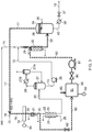
- Figure 1 shows one prior art manufacturing plant arranged to contain an integrated process for ammonium nitrate.
- a gaseous mixture (16) comprising ammonia, water vapour and oxygen (18) is fed to an oxidizer (19).
- the oxidizer (19) typically contains gauzes made of a suitable catalyst for oxidizing ammonia to NOx.
- An example of a commonly used catalyst is a platinum-rhodium catalyst.
- the NOx out-put (20) from the oxidizer (19) is then fed to a first heat exchanger (21) where the reaction mixture is cooled to a temperature above the level of dew point (e.g., to a temperature of the order of 140°C) by heat exchange with a heat transfer fluid such as water, pressurized single-phase water or oil.
- a heat transfer fluid such as water, pressurized single-phase water or oil.
- the cooled NOx out-put (20) On exiting from the first heat exchanger (21) the cooled NOx out-put (20) is fed to a second heat exchanger (22).
- the second heat exchanger (22) contains channels (23) passing the NOx out-put (20) counter-current to the heat-exchanger fluid (25) in other channels (24). Nitrogen monoxide in the NOx out-put will have started to oxidize upon exit of the first heat exchanger (21). Gases that are not condensed or absorbed in the condensed liquid in the heat exchangers (21 and 22) are separated from the nitric acid, to form a tail gas (26), by a phase separator (27), leaving a gas-free nitric acid stream (13).
- the principal components of the tail gas (26) will be excess unreacted oxygen, argon and other impurities introduced with the oxygen feed to the process, nitrogen and nitrous oxide formed as by-products in the oxidizer, and water vapour.
- the tail gas exiting the phase separator (27) will also contain nitrous gases.
- the tail gas may be fed from the phase separator (27) to a further separator (27A) by way of a chiller-condenser (27B), these vessels may act to effectively provide reaction-absorption subsequent to that provided in the second heat exchanger (22).
- the hot, pressurized nitric acid stream (13) is mixed with the gaseous ammonia feed (14), at a similar pressure, and fed to the ammonium nitrate reaction chamber (29), giving rise to the reaction stream (33), which comprises a two-phase stream consisting of ammonium nitrate solution in the liquid phase and a steam/ammonia mixture in the vapour phase. It is suitable that about 40% of this two-phase stream will be ammonium nitrate.
- the release of reaction heat gives rise to vaporization of water into the vapour phase and, consequently, partial concentration of the ammonium nitrate within the liquid phase.
- a demister device (36) is located within an ammonium nitrate tank (34) and is employed to assist the disengagement of liquid droplets containing ammonium nitrate from the steam.
- An external source (35) of wash- water is provided for spraying the demister device as and when required, for example during start-up or shut-down of the process.
- the aqueous ammonium nitrate solution (15) from the ammonium nitrate tank (34) is passed through a pressure let-down valve (37) by way of a cooler (38) to avoid flashing of the solution in the valve.
- an external heat source (not shown) may be employed to heat a fluid loop (A) to a suitable temperature approximating that employed in steady-state operation of the process.
- Water may then be introduced into the nitric acid separator 27 or a separate start-up tank (not shown) may be installed in parallel with separator 27, for example, allowing generation of water vapour in the evaporator(s) and, consequently, providing for circulation of water vapour through the oxidizer.
- Figure 2 is a system according to one embodiment.
- an acidic start-up water-tank (90) for containing an acidic aqueous solution (91) is installed between a condenser (22) and an evaporator (30).
- the temperature of the catalyst in oxidizer (19) is below the ignition temperature.
- the acidic start-up water-tank (90) is filled with water and a pH adjusting agent such as an acid to form an acidic aqueous solution in the tank.
- the acidic start-up water-tank can be filled with an acidic aqueous solution.
- Inlet (85) may be used to fill the tank.
- the acidic aqueous solution (92) from the acidic start-up water-tank (90) enters the nitric acid production line by a pump (81) when a start-up valve (80) is in open position.
- the acidic aqueous solution and flows through the ammonium nitrate reaction chamber and the ammonium nitrate evaporator (30) wherein the acidic aqueous solution is evaporated by heating.
- the heated acidic aqueous solution thus enters the ammonium nitrate tank (34), and passes the oxidizer (19) in the form of water vapour. From the oxidizer the water vapour is passed through the heat exchanger and the condenser back to the start-up water tank via line (93).
- the circulation provided by the acidic start-up water-tank is indicated by dashed arrows in Figure 2 .
- a temperature sensor (95) is installed in the oxidizer.
- the temperature threshold of the catalyst in the oxidizer (19) is reached, ammonia oxidation is initiated and it is often desired to let the NOx output (20) from the oxidizer (19) bypass the acidic start-up water-tank (90). This can for example be achieved by closing of a production output valve (82) in the connection between the acidic start-up water-tank and the condenser (22).
- the temperature sensor measures the temperature of the catalyst which may be in the form of catalyst gauzes.
- Aqueous nitric acid can be injected directly into the acidic start-up water-tank (90) via pH adjusting agent inlet (85) to ensure acidic pH in the solution therein (91).
- the pH of the solution (91) in the acidic start-up water-tank (90) can be controlled by a pH sensor (94) which is connected to an injector (not shown) supplying aqueous nitric acid. If the sensor measures a pH outside a desired range, it can trigger injection of nitric acid via inlet (85) into the solution inside the start-up water-tank (90) in an amount sufficient to achieve a pH inside a desired range.
- the composition of the gaseous mixture (16) entering the oxidizer can be different during start-up compared to during production of an aqueous ammonium nitrate solution.
- the gaseous mixture (16) may initially consist primarily of water vapour and potentially some ammonia.
- the composition of the gaseous mixture (16) can be adjusted to comprise ammonia, water vapour and oxygen.
- the gaseous mixture (16) will comprise water vapour, ammonia and oxygen.
- Figure 3 discloses an embodiment of a plant where the start-up circulation of acidic start-up fluid by-passes the condenser (22) and the ammonium nitrate reaction chamber (29). Accordingly the main inlet (93) of the start-up water tank is in fluid communication with the outlet of the oxidizer and the heat exchanger. The outlet (92) of the pump (81) is in direct fluid communication with the inlet to the ammonium nitrate evaporator (30).
- FIG 4 illustrates an embodiment where the acidic start-up fluid is introduced directly upstream of the main pump (28) so that the main pump may be used to transfer the start-up fluid (92) to the ammonium nitrate evaporator (30).
- the start-up fluid passes through the ammonium nitrate tank (34), the oxidizer (19), the heat exchanger, the condenser and into the phase separator (27). From there it passes via valve (82) to the start-up tank.
- a valve (83) is installed to close off the flow directly from the phase separator to the pump during start-up. When production is initiated valve (83) is opened and valves (82) and (80) are closed.
- the manufacturing plant according to the present disclosure can produce an aqueous solution of ammonium nitrate, but this is not necessarily the end product. If desired, the aqueous solution of ammonium nitrate can be dried by conventional methods to obtain a powder or particles.
Landscapes
- Chemical & Material Sciences (AREA)
- Organic Chemistry (AREA)
- Inorganic Chemistry (AREA)
- Chemical Kinetics & Catalysis (AREA)
- Heat Treatment Of Water, Waste Water Or Sewage (AREA)
- Fertilizers (AREA)
- Hydroponics (AREA)
- Inorganic Compounds Of Heavy Metals (AREA)
- Agricultural Chemicals And Associated Chemicals (AREA)
- Preventing Corrosion Or Incrustation Of Metals (AREA)
- Cultivation Of Plants (AREA)
- Vaporization, Distillation, Condensation, Sublimation, And Cold Traps (AREA)
- Treatment Of Water By Oxidation Or Reduction (AREA)
Claims (15)
- Installation de fabrication pour produire du nitrate d'ammonium comprenant :a) un dispositif d'oxydation avec un catalyseur capable d'oxyder de l'ammoniac en oxyde d'azote comprenant une entrée de vapeur et une sortie ;b) un condenseur raccordé fluidiquement à la sortie du dispositif d'oxydation ;c) un séparateur de phase raccordé fluidiquement au condenseur; dans laquelle le séparateur de phase comprend une sortie de gaz et une sortie de liquide ;d) une chambre de réaction de nitrate d'ammonium raccordée fluidiquement à la sortie de liquide du séparateur de phase ;e) un évaporateur raccordé fluidiquement à la chambre de réaction de nitrate d'ammonium ;f) un réservoir de nitrate d'ammonium destiné à contenir une solution aqueuse de nitrate d'ammonium raccordé fluidiquement à l'évaporateur, dans laquelle le réservoir de nitrate d'ammonium comprend une sortie de vapeur raccordée fluidiquement à l'entrée de vapeur du dispositif d'oxydation ; etg) un réservoir d'eau de démarrage destiné à contenir un fluide aqueux acide raccordé fluidiquement à l'évaporateur, dans laquelle le réservoir d'eau de démarrage est raccordé à une source de fluide aqueux acide ou à une source d'agent d'ajustement du pH, et dans laquelle le réservoir d'eau de démarrage comprend un capteur de pH pour mesurer le pH du fluide aqueux acide.
- Installation de fabrication selon la revendication 1, dans laquelle le réservoir d'eau de démarrage contient une solution aqueuse acide, de préférence de l'acide nitrique, et
de préférence le pH du fluide aqueux acide dans le réservoir d'eau de démarrage est inférieur à 3,0, mesuré dans des conditions standards. - Installation de fabrication selon l'une quelconque des revendications 1 et 2, comprenant en outre un échangeur de chaleur agencé en aval de la sortie du dispositif d'oxydation et en amont du condenseur.
- Installation de fabrication selon l'une quelconque des revendications 1 à 3, dans laquelle le réservoir d'eau de démarrage comprend une entrée raccordée directement à la sortie du dispositif d'oxydation, à une sortie de l'échangeur de chaleur le cas échéant, à une sortie du condenseur, à la sortie de liquide du séparateur de phase, ou à une sortie de la chambre de réaction de nitrate d'ammonium et le réservoir d'eau de démarrage comprend une sortie raccordée fluidiquement à une entrée de l'évaporateur.
- Installation de fabrication selon l'une quelconque des revendications 1 à 4, dans laquelle une entrée du réservoir d'eau de démarrage est raccordée directement à la sortie du condenseur et une sortie du réservoir d'eau de démarrage est raccordée à une entrée de la chambre de réaction de nitrate d'ammonium, ou
dans laquelle une entrée du réservoir d'eau de démarrage est raccordée directement à la sortie du condenseur et la sortie du réservoir d'eau de démarrage est raccordée à une entrée de l'évaporateur. - Installation de fabrication selon l'une quelconque des revendications 1 à 5, comprenant en outre une pompe agencée en aval du réservoir d'eau de démarrage et en amont de l'évaporateur, dans laquelle la pompe est capable de transporter le fluide aqueux acide du réservoir d'eau de démarrage à l'évaporateur.
- Installation de fabrication selon l'une quelconque des revendications 1 à 6, dans laquelle le réservoir d'eau de démarrage destiné à contenir un fluide aqueux acide est configuré pour établir une circulation de fluide aqueux acide à travers l'évaporateur, le réservoir de nitrate d'ammonium et le dispositif d'oxydation.
- Installation de fabrication selon l'une quelconque des revendications 1 à 7, comprenant en outre au moins une vanne de sortie de production en amont du réservoir d'eau de démarrage acide et en aval du dispositif d'oxydation, d'un échangeur de chaleur le cas échéant, du condenseur ou du séparateur de phase, dans laquelle la vanne de sortie de production permet un raccordement fluidique entre le dispositif d'oxydation, l'échangeur de chaleur le cas échéant, le condenseur ou le séparateur de phase et le réservoir d'eau de démarrage acide lorsqu'elle est en position ouverte et empêche le raccordement fluidique lorsqu'elle est en position fermée et éventuellement au moins une vanne de démarrage dans le raccordement fluidique entre le réservoir d'eau de démarrage et la chambre de réaction de nitrate d'ammonium ou l'évaporateur, dans laquelle la vanne de démarrage permet un raccordement fluidique entre le réservoir d'eau de démarrage et la chambre de réaction de nitrate d'ammonium ou l'évaporateur lorsqu'elle est en position ouverte et empêche le raccordement fluidique lorsqu'elle est en position fermée.
- Installation de fabrication selon l'une quelconque des revendications 1 à 8, dans laquelle le dispositif d'oxydation comprend un capteur de température destiné à mesurer la température à l'intérieur du dispositif d'oxydation.
- Procédé de démarrage d'une installation de fabrication selon la revendication 1, comprenant les étapes dea) pompage d'un fluide aqueux acide du réservoir d'eau de démarrage à l'évaporateur, dans lequel le fluide aqueux acide dans le réservoir d'eau de démarrage est de préférence de l'acide nitrique ;b) chauffage du fluide aqueux acide dans l'évaporateur pour générer de la vapeur d'eau ;c) fourniture de la vapeur d'eau au réservoir de nitrate d'ammonium ;d) apport de vapeur du réservoir de nitrate d'ammonium au dispositif d'oxydatione) apport de la sortie du dispositif d'oxydation directement ou indirectement dans le réservoir d'eau de démarrage,f) poursuite des étapes a) à e) jusqu'à ce qu'une température présélectionnée dans le dispositif d'oxydation soit atteinte,comprenant éventuellement la mesure de la température dans le dispositif d'oxydation, de préférence la température du catalyseur.
- Procédé selon la revendication 10, dans lequel l'installation de fabrication comprend en outre au moins une vanne de sortie de production en amont du réservoir d'eau de démarrage et en aval du dispositif d'oxydation, d'un échangeur de chaleur le cas échéant, du condenseur, ou du séparateur de phase, dans lequel l'étape de pompage a) est suivie de l'ouverture de la vanne de sortie de production moyennant quoi la sortie provenant du dispositif d'oxydation, de l'échangeur de chaleur le cas échéant, du condenseur, ou du séparateur de phase est renvoyée dans le réservoir d'eau de démarrage et éventuellement
dans lequel l'installation de fabrication comprend en outre au moins une vanne de démarrage dans le raccordement fluidique entre le réservoir d'eau de démarrage et la chambre de réaction de nitrate d'ammonium ou l'évaporateur, dans lequel l'étape de pompage a) est ultérieure à l'ouverture de la vanne de démarrage qui permet l'apport du fluide aqueux acide du réservoir d'eau de démarrage à l'évaporateur. - Procédé selon la revendication 11, comprenant en outre la mesure de la température dans le dispositif d'oxydation et la fermeture de la vanne de sortie de production après que la température présélectionnée dans le dispositif d'oxydation est atteinte et comprenant éventuellement la fermeture de la vanne de démarrage après que la température présélectionnée dans le dispositif d'oxydation est atteinte,
dans lequel la température présélectionnée est de préférence environ la température d'inflammation du catalyseur dans le dispositif d'oxydation. - Procédé selon l'une quelconque des revendications 10 à 12, dans lequel l'étape de chauffage b) fournit à la vapeur apportée au dispositif d'oxydation à l'étape c) une température supérieure au point de rosée pour de la vapeur dans le dispositif d'oxydation.
- Procédé selon l'une quelconque des revendications 10 à 13, dans lequel la vapeur provenant du réservoir de nitrate d'ammonium aqueux entrant dans le dispositif d'oxydation est sensiblement de la vapeur d'eau ou sensiblement de la vapeur d'eau et de l'ammoniac.
- Procédé selon l'une quelconque des revendications 10 à 14, dans lequel le procédé comprend en outre la mesure du pH du fluide aqueux acide dans le réservoir d'eau de démarrage et l'addition d'un agent d'ajustement de pH si le pH est supérieur à une valeur prédéfinie, de préférence la valeur prédéfinie est de 3,0 et l'agent d'ajustement de pH est l'acide nitrique.
Applications Claiming Priority (2)
| Application Number | Priority Date | Filing Date | Title |
|---|---|---|---|
| EP16176420.4A EP3263523A1 (fr) | 2016-06-27 | 2016-06-27 | Installation de production de nitrate d'ammonium et procédé de démarrage de celui-ci |
| PCT/EP2017/065679 WO2018001946A1 (fr) | 2016-06-27 | 2017-06-26 | Installation de production de nitrate d'ammonium et procédé de démarrage associé |
Publications (2)
| Publication Number | Publication Date |
|---|---|
| EP3475226A1 EP3475226A1 (fr) | 2019-05-01 |
| EP3475226B1 true EP3475226B1 (fr) | 2020-06-17 |
Family
ID=56321756
Family Applications (2)
| Application Number | Title | Priority Date | Filing Date |
|---|---|---|---|
| EP16176420.4A Withdrawn EP3263523A1 (fr) | 2016-06-27 | 2016-06-27 | Installation de production de nitrate d'ammonium et procédé de démarrage de celui-ci |
| EP17735048.5A Active EP3475226B1 (fr) | 2016-06-27 | 2017-06-26 | Installation de production de nitrate d'ammonium et procédé de démarrage de celui-ci |
Family Applications Before (1)
| Application Number | Title | Priority Date | Filing Date |
|---|---|---|---|
| EP16176420.4A Withdrawn EP3263523A1 (fr) | 2016-06-27 | 2016-06-27 | Installation de production de nitrate d'ammonium et procédé de démarrage de celui-ci |
Country Status (11)
| Country | Link |
|---|---|
| EP (2) | EP3263523A1 (fr) |
| AR (1) | AR108887A1 (fr) |
| AU (1) | AU2017291107B2 (fr) |
| BR (1) | BR112018074745A2 (fr) |
| CA (1) | CA3028262A1 (fr) |
| CL (1) | CL2018003775A1 (fr) |
| CO (1) | CO2018013458A2 (fr) |
| MX (1) | MX2018014677A (fr) |
| PE (1) | PE20190163A1 (fr) |
| WO (1) | WO2018001946A1 (fr) |
| ZA (1) | ZA201807946B (fr) |
Families Citing this family (1)
| Publication number | Priority date | Publication date | Assignee | Title |
|---|---|---|---|---|
| CN112028089B (zh) * | 2020-09-30 | 2024-02-06 | 四川金象赛瑞化工股份有限公司 | 一种硝酸铵的生产装置和方法 |
Family Cites Families (6)
| Publication number | Priority date | Publication date | Assignee | Title |
|---|---|---|---|---|
| US3881004A (en) * | 1972-12-29 | 1975-04-29 | Masar Inc | Ammonium nitrate plant |
| DE3347404A1 (de) | 1983-12-29 | 1985-07-11 | Ruhrchemie Ag, 4200 Oberhausen | Verfahren zur herstellung von ammonnitrat |
| US4863893A (en) | 1986-08-06 | 1989-09-05 | Engelhard Corporation | Low temperature light off ammonia oxidation |
| US5256387A (en) | 1992-05-11 | 1993-10-26 | Scientific Design Company, Inc. | Catalyst for the production of nitric acid by oxidation of ammonia |
| SI2709953T1 (sl) * | 2011-05-16 | 2017-12-29 | The University Of Sydney | Integrirani postopek za proizvodnjo amonijevega nitrata |
| AT511531B1 (de) | 2011-05-18 | 2014-06-15 | Sandvik Mining & Constr Oy | Anordnung zur festlegung eines meissels |
-
2016
- 2016-06-27 EP EP16176420.4A patent/EP3263523A1/fr not_active Withdrawn
-
2017
- 2017-06-26 EP EP17735048.5A patent/EP3475226B1/fr active Active
- 2017-06-26 BR BR112018074745-9A patent/BR112018074745A2/pt not_active Application Discontinuation
- 2017-06-26 MX MX2018014677A patent/MX2018014677A/es unknown
- 2017-06-26 PE PE2018003081A patent/PE20190163A1/es unknown
- 2017-06-26 CA CA3028262A patent/CA3028262A1/fr not_active Abandoned
- 2017-06-26 AR ARP170101763A patent/AR108887A1/es unknown
- 2017-06-26 AU AU2017291107A patent/AU2017291107B2/en not_active Expired - Fee Related
- 2017-06-26 WO PCT/EP2017/065679 patent/WO2018001946A1/fr not_active Ceased
-
2018
- 2018-11-23 ZA ZA2018/07946A patent/ZA201807946B/en unknown
- 2018-12-13 CO CONC2018/0013458A patent/CO2018013458A2/es unknown
- 2018-12-21 CL CL2018003775A patent/CL2018003775A1/es unknown
Non-Patent Citations (1)
| Title |
|---|
| None * |
Also Published As
| Publication number | Publication date |
|---|---|
| CL2018003775A1 (es) | 2019-02-15 |
| WO2018001946A1 (fr) | 2018-01-04 |
| EP3263523A1 (fr) | 2018-01-03 |
| CO2018013458A2 (es) | 2018-12-28 |
| AU2017291107B2 (en) | 2020-06-11 |
| PE20190163A1 (es) | 2019-01-30 |
| EP3475226A1 (fr) | 2019-05-01 |
| MX2018014677A (es) | 2019-03-28 |
| ZA201807946B (en) | 2020-05-27 |
| BR112018074745A2 (pt) | 2019-03-06 |
| AR108887A1 (es) | 2018-10-03 |
| CA3028262A1 (fr) | 2018-01-04 |
| AU2017291107A1 (en) | 2019-01-24 |
Similar Documents
| Publication | Publication Date | Title |
|---|---|---|
| US9493364B2 (en) | Process for producing ammonium nitrate | |
| US8628745B2 (en) | Integrated process for producing ammonium nitrate | |
| US20250282614A1 (en) | Process for cracking ammonia | |
| EP3475226B1 (fr) | Installation de production de nitrate d'ammonium et procédé de démarrage de celui-ci | |
| US11643327B2 (en) | Method for the catalytic oxidation of ammonia gas | |
| US9199849B2 (en) | Process for producing nitric acid | |
| CN111108064A (zh) | 生产硝酸的工艺 |
Legal Events
| Date | Code | Title | Description |
|---|---|---|---|
| STAA | Information on the status of an ep patent application or granted ep patent |
Free format text: STATUS: UNKNOWN |
|
| STAA | Information on the status of an ep patent application or granted ep patent |
Free format text: STATUS: THE INTERNATIONAL PUBLICATION HAS BEEN MADE |
|
| PUAI | Public reference made under article 153(3) epc to a published international application that has entered the european phase |
Free format text: ORIGINAL CODE: 0009012 |
|
| STAA | Information on the status of an ep patent application or granted ep patent |
Free format text: STATUS: REQUEST FOR EXAMINATION WAS MADE |
|
| 17P | Request for examination filed |
Effective date: 20190111 |
|
| AK | Designated contracting states |
Kind code of ref document: A1 Designated state(s): AL AT BE BG CH CY CZ DE DK EE ES FI FR GB GR HR HU IE IS IT LI LT LU LV MC MK MT NL NO PL PT RO RS SE SI SK SM TR |
|
| AX | Request for extension of the european patent |
Extension state: BA ME |
|
| DAV | Request for validation of the european patent (deleted) | ||
| DAX | Request for extension of the european patent (deleted) | ||
| GRAP | Despatch of communication of intention to grant a patent |
Free format text: ORIGINAL CODE: EPIDOSNIGR1 |
|
| STAA | Information on the status of an ep patent application or granted ep patent |
Free format text: STATUS: GRANT OF PATENT IS INTENDED |
|
| INTG | Intention to grant announced |
Effective date: 20200131 |
|
| GRAS | Grant fee paid |
Free format text: ORIGINAL CODE: EPIDOSNIGR3 |
|
| GRAA | (expected) grant |
Free format text: ORIGINAL CODE: 0009210 |
|
| STAA | Information on the status of an ep patent application or granted ep patent |
Free format text: STATUS: THE PATENT HAS BEEN GRANTED |
|
| AK | Designated contracting states |
Kind code of ref document: B1 Designated state(s): AL AT BE BG CH CY CZ DE DK EE ES FI FR GB GR HR HU IE IS IT LI LT LU LV MC MK MT NL NO PL PT RO RS SE SI SK SM TR |
|
| REG | Reference to a national code |
Ref country code: GB Ref legal event code: FG4D |
|
| REG | Reference to a national code |
Ref country code: CH Ref legal event code: EP |
|
| REG | Reference to a national code |
Ref country code: IE Ref legal event code: FG4D |
|
| REG | Reference to a national code |
Ref country code: DE Ref legal event code: R096 Ref document number: 602017018363 Country of ref document: DE |
|
| REG | Reference to a national code |
Ref country code: AT Ref legal event code: REF Ref document number: 1281081 Country of ref document: AT Kind code of ref document: T Effective date: 20200715 |
|
| PGFP | Annual fee paid to national office [announced via postgrant information from national office to epo] |
Ref country code: FR Payment date: 20200611 Year of fee payment: 4 Ref country code: DE Payment date: 20200617 Year of fee payment: 4 |
|
| PG25 | Lapsed in a contracting state [announced via postgrant information from national office to epo] |
Ref country code: NO Free format text: LAPSE BECAUSE OF FAILURE TO SUBMIT A TRANSLATION OF THE DESCRIPTION OR TO PAY THE FEE WITHIN THE PRESCRIBED TIME-LIMIT Effective date: 20200917 Ref country code: SE Free format text: LAPSE BECAUSE OF FAILURE TO SUBMIT A TRANSLATION OF THE DESCRIPTION OR TO PAY THE FEE WITHIN THE PRESCRIBED TIME-LIMIT Effective date: 20200617 Ref country code: FI Free format text: LAPSE BECAUSE OF FAILURE TO SUBMIT A TRANSLATION OF THE DESCRIPTION OR TO PAY THE FEE WITHIN THE PRESCRIBED TIME-LIMIT Effective date: 20200617 Ref country code: GR Free format text: LAPSE BECAUSE OF FAILURE TO SUBMIT A TRANSLATION OF THE DESCRIPTION OR TO PAY THE FEE WITHIN THE PRESCRIBED TIME-LIMIT Effective date: 20200918 Ref country code: LT Free format text: LAPSE BECAUSE OF FAILURE TO SUBMIT A TRANSLATION OF THE DESCRIPTION OR TO PAY THE FEE WITHIN THE PRESCRIBED TIME-LIMIT Effective date: 20200617 |
|
| REG | Reference to a national code |
Ref country code: LT Ref legal event code: MG4D |
|
| REG | Reference to a national code |
Ref country code: NL Ref legal event code: MP Effective date: 20200617 |
|
| PG25 | Lapsed in a contracting state [announced via postgrant information from national office to epo] |
Ref country code: RS Free format text: LAPSE BECAUSE OF FAILURE TO SUBMIT A TRANSLATION OF THE DESCRIPTION OR TO PAY THE FEE WITHIN THE PRESCRIBED TIME-LIMIT Effective date: 20200617 Ref country code: HR Free format text: LAPSE BECAUSE OF FAILURE TO SUBMIT A TRANSLATION OF THE DESCRIPTION OR TO PAY THE FEE WITHIN THE PRESCRIBED TIME-LIMIT Effective date: 20200617 Ref country code: LV Free format text: LAPSE BECAUSE OF FAILURE TO SUBMIT A TRANSLATION OF THE DESCRIPTION OR TO PAY THE FEE WITHIN THE PRESCRIBED TIME-LIMIT Effective date: 20200617 Ref country code: BG Free format text: LAPSE BECAUSE OF FAILURE TO SUBMIT A TRANSLATION OF THE DESCRIPTION OR TO PAY THE FEE WITHIN THE PRESCRIBED TIME-LIMIT Effective date: 20200917 |
|
| REG | Reference to a national code |
Ref country code: AT Ref legal event code: MK05 Ref document number: 1281081 Country of ref document: AT Kind code of ref document: T Effective date: 20200617 |
|
| PG25 | Lapsed in a contracting state [announced via postgrant information from national office to epo] |
Ref country code: NL Free format text: LAPSE BECAUSE OF FAILURE TO SUBMIT A TRANSLATION OF THE DESCRIPTION OR TO PAY THE FEE WITHIN THE PRESCRIBED TIME-LIMIT Effective date: 20200617 Ref country code: AL Free format text: LAPSE BECAUSE OF FAILURE TO SUBMIT A TRANSLATION OF THE DESCRIPTION OR TO PAY THE FEE WITHIN THE PRESCRIBED TIME-LIMIT Effective date: 20200617 |
|
| PG25 | Lapsed in a contracting state [announced via postgrant information from national office to epo] |
Ref country code: RO Free format text: LAPSE BECAUSE OF FAILURE TO SUBMIT A TRANSLATION OF THE DESCRIPTION OR TO PAY THE FEE WITHIN THE PRESCRIBED TIME-LIMIT Effective date: 20200617 Ref country code: IT Free format text: LAPSE BECAUSE OF FAILURE TO SUBMIT A TRANSLATION OF THE DESCRIPTION OR TO PAY THE FEE WITHIN THE PRESCRIBED TIME-LIMIT Effective date: 20200617 Ref country code: SM Free format text: LAPSE BECAUSE OF FAILURE TO SUBMIT A TRANSLATION OF THE DESCRIPTION OR TO PAY THE FEE WITHIN THE PRESCRIBED TIME-LIMIT Effective date: 20200617 Ref country code: AT Free format text: LAPSE BECAUSE OF FAILURE TO SUBMIT A TRANSLATION OF THE DESCRIPTION OR TO PAY THE FEE WITHIN THE PRESCRIBED TIME-LIMIT Effective date: 20200617 Ref country code: PT Free format text: LAPSE BECAUSE OF FAILURE TO SUBMIT A TRANSLATION OF THE DESCRIPTION OR TO PAY THE FEE WITHIN THE PRESCRIBED TIME-LIMIT Effective date: 20201019 Ref country code: EE Free format text: LAPSE BECAUSE OF FAILURE TO SUBMIT A TRANSLATION OF THE DESCRIPTION OR TO PAY THE FEE WITHIN THE PRESCRIBED TIME-LIMIT Effective date: 20200617 Ref country code: ES Free format text: LAPSE BECAUSE OF FAILURE TO SUBMIT A TRANSLATION OF THE DESCRIPTION OR TO PAY THE FEE WITHIN THE PRESCRIBED TIME-LIMIT Effective date: 20200617 Ref country code: CZ Free format text: LAPSE BECAUSE OF FAILURE TO SUBMIT A TRANSLATION OF THE DESCRIPTION OR TO PAY THE FEE WITHIN THE PRESCRIBED TIME-LIMIT Effective date: 20200617 |
|
| REG | Reference to a national code |
Ref country code: CH Ref legal event code: PL |
|
| PG25 | Lapsed in a contracting state [announced via postgrant information from national office to epo] |
Ref country code: SK Free format text: LAPSE BECAUSE OF FAILURE TO SUBMIT A TRANSLATION OF THE DESCRIPTION OR TO PAY THE FEE WITHIN THE PRESCRIBED TIME-LIMIT Effective date: 20200617 Ref country code: PL Free format text: LAPSE BECAUSE OF FAILURE TO SUBMIT A TRANSLATION OF THE DESCRIPTION OR TO PAY THE FEE WITHIN THE PRESCRIBED TIME-LIMIT Effective date: 20200617 Ref country code: IS Free format text: LAPSE BECAUSE OF FAILURE TO SUBMIT A TRANSLATION OF THE DESCRIPTION OR TO PAY THE FEE WITHIN THE PRESCRIBED TIME-LIMIT Effective date: 20201017 |
|
| REG | Reference to a national code |
Ref country code: DE Ref legal event code: R097 Ref document number: 602017018363 Country of ref document: DE |
|
| PG25 | Lapsed in a contracting state [announced via postgrant information from national office to epo] |
Ref country code: MC Free format text: LAPSE BECAUSE OF FAILURE TO SUBMIT A TRANSLATION OF THE DESCRIPTION OR TO PAY THE FEE WITHIN THE PRESCRIBED TIME-LIMIT Effective date: 20200617 Ref country code: LU Free format text: LAPSE BECAUSE OF NON-PAYMENT OF DUE FEES Effective date: 20200626 |
|
| REG | Reference to a national code |
Ref country code: BE Ref legal event code: MM Effective date: 20200630 |
|
| PLBE | No opposition filed within time limit |
Free format text: ORIGINAL CODE: 0009261 |
|
| STAA | Information on the status of an ep patent application or granted ep patent |
Free format text: STATUS: NO OPPOSITION FILED WITHIN TIME LIMIT |
|
| PG25 | Lapsed in a contracting state [announced via postgrant information from national office to epo] |
Ref country code: LI Free format text: LAPSE BECAUSE OF NON-PAYMENT OF DUE FEES Effective date: 20200630 Ref country code: CH Free format text: LAPSE BECAUSE OF NON-PAYMENT OF DUE FEES Effective date: 20200630 Ref country code: DK Free format text: LAPSE BECAUSE OF FAILURE TO SUBMIT A TRANSLATION OF THE DESCRIPTION OR TO PAY THE FEE WITHIN THE PRESCRIBED TIME-LIMIT Effective date: 20200617 Ref country code: IE Free format text: LAPSE BECAUSE OF NON-PAYMENT OF DUE FEES Effective date: 20200626 |
|
| 26N | No opposition filed |
Effective date: 20210318 |
|
| PG25 | Lapsed in a contracting state [announced via postgrant information from national office to epo] |
Ref country code: BE Free format text: LAPSE BECAUSE OF NON-PAYMENT OF DUE FEES Effective date: 20200630 Ref country code: SI Free format text: LAPSE BECAUSE OF FAILURE TO SUBMIT A TRANSLATION OF THE DESCRIPTION OR TO PAY THE FEE WITHIN THE PRESCRIBED TIME-LIMIT Effective date: 20200617 |
|
| REG | Reference to a national code |
Ref country code: DE Ref legal event code: R119 Ref document number: 602017018363 Country of ref document: DE |
|
| GBPC | Gb: european patent ceased through non-payment of renewal fee |
Effective date: 20210626 |
|
| PG25 | Lapsed in a contracting state [announced via postgrant information from national office to epo] |
Ref country code: GB Free format text: LAPSE BECAUSE OF NON-PAYMENT OF DUE FEES Effective date: 20210626 Ref country code: DE Free format text: LAPSE BECAUSE OF NON-PAYMENT OF DUE FEES Effective date: 20220101 |
|
| PG25 | Lapsed in a contracting state [announced via postgrant information from national office to epo] |
Ref country code: TR Free format text: LAPSE BECAUSE OF FAILURE TO SUBMIT A TRANSLATION OF THE DESCRIPTION OR TO PAY THE FEE WITHIN THE PRESCRIBED TIME-LIMIT Effective date: 20200617 Ref country code: MT Free format text: LAPSE BECAUSE OF FAILURE TO SUBMIT A TRANSLATION OF THE DESCRIPTION OR TO PAY THE FEE WITHIN THE PRESCRIBED TIME-LIMIT Effective date: 20200617 Ref country code: FR Free format text: LAPSE BECAUSE OF NON-PAYMENT OF DUE FEES Effective date: 20210630 Ref country code: CY Free format text: LAPSE BECAUSE OF FAILURE TO SUBMIT A TRANSLATION OF THE DESCRIPTION OR TO PAY THE FEE WITHIN THE PRESCRIBED TIME-LIMIT Effective date: 20200617 |
|
| PG25 | Lapsed in a contracting state [announced via postgrant information from national office to epo] |
Ref country code: MK Free format text: LAPSE BECAUSE OF FAILURE TO SUBMIT A TRANSLATION OF THE DESCRIPTION OR TO PAY THE FEE WITHIN THE PRESCRIBED TIME-LIMIT Effective date: 20200617 |