EP3478607B1 - Système de transport et supports d'articles associés - Google Patents
Système de transport et supports d'articles associés Download PDFInfo
- Publication number
- EP3478607B1 EP3478607B1 EP17820613.2A EP17820613A EP3478607B1 EP 3478607 B1 EP3478607 B1 EP 3478607B1 EP 17820613 A EP17820613 A EP 17820613A EP 3478607 B1 EP3478607 B1 EP 3478607B1
- Authority
- EP
- European Patent Office
- Prior art keywords
- carrier
- article carrier
- connecting member
- article
- conveyor
- Prior art date
- Legal status (The legal status is an assumption and is not a legal conclusion. Google has not performed a legal analysis and makes no representation as to the accuracy of the status listed.)
- Active
Links
Images


Classifications
-
- B—PERFORMING OPERATIONS; TRANSPORTING
- B07—SEPARATING SOLIDS FROM SOLIDS; SORTING
- B07C—POSTAL SORTING; SORTING INDIVIDUAL ARTICLES, OR BULK MATERIAL FIT TO BE SORTED PIECE-MEAL, e.g. BY PICKING
- B07C5/00—Sorting according to a characteristic or feature of the articles or material being sorted, e.g. by control effected by devices which detect or measure such characteristic or feature; Sorting by manually actuated devices, e.g. switches
- B07C5/16—Sorting according to weight
- B07C5/22—Sorting according to weight using a plurality of stationary weighing mechanisms
-
- B—PERFORMING OPERATIONS; TRANSPORTING
- B07—SEPARATING SOLIDS FROM SOLIDS; SORTING
- B07C—POSTAL SORTING; SORTING INDIVIDUAL ARTICLES, OR BULK MATERIAL FIT TO BE SORTED PIECE-MEAL, e.g. BY PICKING
- B07C5/00—Sorting according to a characteristic or feature of the articles or material being sorted, e.g. by control effected by devices which detect or measure such characteristic or feature; Sorting by manually actuated devices, e.g. switches
- B07C5/16—Sorting according to weight
-
- B—PERFORMING OPERATIONS; TRANSPORTING
- B07—SEPARATING SOLIDS FROM SOLIDS; SORTING
- B07C—POSTAL SORTING; SORTING INDIVIDUAL ARTICLES, OR BULK MATERIAL FIT TO BE SORTED PIECE-MEAL, e.g. BY PICKING
- B07C5/00—Sorting according to a characteristic or feature of the articles or material being sorted, e.g. by control effected by devices which detect or measure such characteristic or feature; Sorting by manually actuated devices, e.g. switches
- B07C5/36—Sorting apparatus characterised by the means used for distribution
-
- B—PERFORMING OPERATIONS; TRANSPORTING
- B65—CONVEYING; PACKING; STORING; HANDLING THIN OR FILAMENTARY MATERIAL
- B65G—TRANSPORT OR STORAGE DEVICES, e.g. CONVEYORS FOR LOADING OR TIPPING, SHOP CONVEYOR SYSTEMS OR PNEUMATIC TUBE CONVEYORS
- B65G17/00—Conveyors having an endless traction element, e.g. a chain, transmitting movement to a continuous or substantially-continuous load-carrying surface or to a series of individual load-carriers; Endless-chain conveyors in which the chains form the load-carrying surface
- B65G17/16—Conveyors having an endless traction element, e.g. a chain, transmitting movement to a continuous or substantially-continuous load-carrying surface or to a series of individual load-carriers; Endless-chain conveyors in which the chains form the load-carrying surface comprising individual load-carriers which are pivotally mounted, e.g. for free-swinging movement
-
- B—PERFORMING OPERATIONS; TRANSPORTING
- B65—CONVEYING; PACKING; STORING; HANDLING THIN OR FILAMENTARY MATERIAL
- B65G—TRANSPORT OR STORAGE DEVICES, e.g. CONVEYORS FOR LOADING OR TIPPING, SHOP CONVEYOR SYSTEMS OR PNEUMATIC TUBE CONVEYORS
- B65G47/00—Article or material-handling devices associated with conveyors; Methods employing such devices
- B65G47/74—Feeding, transfer, or discharging devices of particular kinds or types
- B65G47/94—Devices for flexing or tilting travelling structures; Throw-off carriages
- B65G47/96—Devices for tilting links or platform
- B65G47/962—Devices for tilting links or platform tilting about an axis substantially parallel to the conveying direction
- B65G47/965—Devices for tilting links or platform tilting about an axis substantially parallel to the conveying direction tilting about a sided-axis, i.e. the axis is not located near the center-line of the load-carrier
-
- B—PERFORMING OPERATIONS; TRANSPORTING
- B07—SEPARATING SOLIDS FROM SOLIDS; SORTING
- B07C—POSTAL SORTING; SORTING INDIVIDUAL ARTICLES, OR BULK MATERIAL FIT TO BE SORTED PIECE-MEAL, e.g. BY PICKING
- B07C2501/00—Sorting according to a characteristic or feature of the articles or material to be sorted
- B07C2501/009—Sorting of fruit
Definitions
- the present invention relates to a conveyor system for articles, particularly for use within a grading apparatus, and to article carriers therefor.
- Grading apparatus for example those used for grading fruit, typically comprise at least one conveyor system comprising an endless conveyor belt or chain (hereinafter “conveyor") to which are mounted a plurality of article carriers.
- Conveyor endless conveyor belt or chain
- a discharge mechanism is used to unload objects at certain points along the conveyor depending on the results of the grading.
- Grading may be based on one or more of a number of factors, including weight, shape, colour, ripeness and any other characteristic.
- the conveyor device described in US 5,230,394 uses article carriers comprising two pairs of rollers on either side of a conveyor, wherein each pair of rollers is fixed together to a single conveyor carriage, enabling both rollers to change as a rigid unit between a transport position and a discharge position.
- the articles are transported individually on a pair of rollers mounted to a carriage and weighing can be conducted for each carriage.
- the applicant's International PCT Publication No. WO2014073987 describes another type of article carrier, in which articles are held on one or both sides of the conveyor on elongate "fingers".
- the article carrier may work well, but an alternative article carrier which allows even more accurate weighing of articles may be desirable.
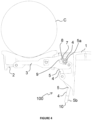
- an article carrier according to one embodiment of the present invention is generally referenced by arrow 100.
- the article carrier 100 comprises a mounting portion 1 for mounting the carrier to a conveyor, for example an endless chain conveyor (not shown), for example by means of a clip or other fastening, such that the conveyor is positioned on a conveyor axis A of the article carrier 100.
- a conveyor for example an endless chain conveyor (not shown), for example by means of a clip or other fastening, such that the conveyor is positioned on a conveyor axis A of the article carrier 100.
- the conveyor axis A is substantially parallel to a longitudinal axis of the conveyor.
- One or more carrier portions 2 are mounted to the mounting portion 1.
- the carrier comprises four carrier portions 2, with two carrier portions on either side of the mounting portion 1.
- other embodiments may have more or fewer carrier portions on either side of the mounting portion 1, or may have (in embodiments not according to the claimed invention) one or (in embodiments of the claimed invention) more than one carrier portions 2 on only one side of the mounting portion 1.
- the article carrier 100 is substantially symmetrical about a central plane which intersects the conveyor axis A and/or the article carrier comprises an axis B of twofold rotational symmetry, such that the article carrier 100 can be mounted to the conveyor in one of two orientations without affecting the performance of the article carrier 100.
- the axis of rotational symmetry B preferably intersects the conveyor axis A.
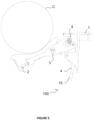
- the carrier portions 2 are provided as elongate "fingers", and define a bowed or cupped shape in order to securely bear an article C (shown in Figure 3 ).
- Each carrier portion 2 is connected to the mounting portion 1 by a connecting member 3.
- the connecting member 3 is rotatably connected to the mounting portion 1 such that it can rotate about a first axis of rotation R1.
- the carrier portion 2 is rotatably connected to the connecting member 3 such that it can rotate relative to the connecting member 3 about a second axis of rotation R2.
- the first and second axes of rotation R1, R2 are spaced apart, and in many embodiments are at opposite ends of the connecting member 3.
- the article carrier 100 is further provided with a connecting member locking means 4.
- the connecting member locking means 4 is moveable between a first position, shown in Figure 3 , wherein the connecting member locking means 4 is engaged with the connecting member 3 and holds the connecting member 3 in a carriage position, and second position, shown in Figures 4-6 , in which the connecting member locking means 4 is disengaged from the connecting member 3, thereby allowing the connecting member 3 to rotate about the first axis of rotation R1 and (if no other surface is supporting the carrier portion 2) to move to a discharge position.
- the connecting member locking means 4 may also be moved to the second, disengaged, position when an item borne by the carrier portion 2 is to be weighed.
- the connecting member locking means 4 comprises a locking means member 5 which is rotatably connected to the mounting portion 1.
- the connection 4a is preferably at a point between the first end 5a and second end 5b of the locking means member 5.
- a first end 5a of the locking means member 5 is provided with an engagement portion 6 which engages a support surface 7 of the connecting member 3 (best seen in Figure 1 ) when the connecting member locking means 4 is engaged with the connecting member 3.
- the support surface 7 is preferably defined by a wall 8 of a recess 9 provided at one end of the connecting member 3.
- the second end 5b of the locking means member 5 comprises a trigger portion 10.
- the trigger portion 10 is moved in a direction away from the mounting portion 1. This may be achieved by use of a suitable actuator (not shown) contacting the trigger portion 10, or by movement of the article carrier 100 past a cam surface.
- the actuator is an electromechanical actuator, although other actuators may be used.
- the article carrier 100 may be moved past a suitable cam surface which bears on the opposite side of the trigger portion 10 and moves it in a direction toward the mounting portion 1.
- a suitable actuator may be used.
- the carrier portion 2 further comprises a rotation limiting portion 11 configured to abut an abutment portion 12 of the connecting member 3 in order to limit rotation of the carrier portion 2 relative to the connecting member 3 such that an article borne, in use, by the carrier portion 2 will not roll off the carrier portion 2 when the connecting member locking means 4 is engaged with the connecting member 3.
- the interaction of the rotation limiting portion 11 and the abutment portion 12 allows substantially 5° of relative rotation, although in other embodiments more or less relative rotation may be allowed, depending on factors such as the shape of the carrier portion 2.
- the abutment portion 12 comprises an aperture or recess 13 in the connecting member 3, and the rotation limiting portion 11 comprises a protrusion or tab 14 which projects into the aperture or recess 13.
- the article carrier 100 shown comprises four carrier portions 2, two of the carrier portions provided on each side of the article carrier.
- each carrier portion 2 comprises bearing means 15 configured to bear on a weighing means 16 in use, when the article A borne by the carrier portions 2 is to be weighed.
- a first carrier portion 2a has a first and second bearing surfaces 17a, 17b, and a second carrier portion 2b, on the same side of the article carrier 100 as the first carrier portion 2a, has third and fourth bearing surfaces 17c, 17d, as best seen in Figure 8 .
- the first and second bearing surfaces 17a, 17b are spaced apart, although in some embodiments they may be substantially contiguous.
- the first, second, third and fourth bearing surfaces 17a-17d are arranged such that a distance between the conveyor axis A and any point on one of the bearing surfaces 17a - 17d, measured orthogonally to the conveyor axis A, is different to a distance between the conveyor axis A and any point on any of the other bearing surfaces 17a-17d, measured orthogonally to the conveyor axis A.
- Arrows D1 to D4, shown on Figure 8 show representative measurements orthogonal to the conveyor axis A.
- Arranging the bearing surfaces 17a-17d in this way means that any line parallel to the conveyor axis A passes through a maximum of one of the first, second and third and fourth bearing surfaces 17a-17d.
- Lines L1 to L4 on Figure 8 show representative lines parallel to the conveyor axis.
- the spacing between the first and second bearing surfaces 17a, 17b is less than that between the third and fourth bearing surfaces 17c, 17d.
- the spacing may be substantially the same.
- first, second, third and fourth bearing surfaces are also arranged such that a distance between the conveyor axis A and any point on one of the bearing surfaces, measured orthogonally to the conveyor axis A, is different to a distance between the conveyor axis A and any point on any of the other bearing surfaces, measured orthogonally to the conveyor axis A, and such that any line parallel to the conveyor axis A passes through a maximum of one of the first, second and third and fourth bearing surfaces.
- a conveyor system can be arranged such that the first carrier means (and any article thereon) can be weighed by a first weighing means at the same time as the second carrier means (and any article thereon) is weighed by a second weighing means.
- a third type of carrier means may also be provided with bearing means (for example provided as downwardly projecting feet with lower bearing surfaces) arranged such that the third carrier means can be weighed by a third weighing means at the same time as the first and second carrier means are weighed by their corresponding weighing means.
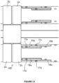
- FIGS 9-11 show a portion of a conveyor system which is provided with first and second weighing means 16a, 16b.
- Each weighing means 16a, 16b has two weighing means contact portions 18a, 18b which are spaced to contact the bearing surfaces 17 of the carrier portions 2 as they move over the weighing means.
- the bearing surfaces 17a, 17b of the first carrier portions 2a contact the weighing means contact portions 18a of the first weighing means 16a, but not the weighing means contact portions 18b of the second weighing means 16b, and the bearing surfaces 17c, 17d of the second carrier portions 2b contact the weighing means contact portions 18b of the second weighing means 16b, but not the weighing means contact portions 18a of the first weighing means 16a.
- the article carriers 100 are arranged such that the first and second carrier portions 2a, 2b are provided alternately, one behind the other (as viewed in the direction of movement of the conveyor).
- the length of each weighing means contact portion 18a, 18b can be substantially equal to (or, if required, slightly less than) a distance between the leading edges of bearing means 15 of successive carrier portions of the same type (that is, successive first carrier portions 2a or successive second carrier portions 2b), while ensuring that bearing means 15 from only one article carrier at a time are in contact with each weighing means contact portion.
- the maximum length of time is allowed for each weighing means to stabilise before or during the recording of a measurement.
- each carrier portion may be resilient, in order to reduce weighing inaccuracies which may be introduced if the weighing means contact portions 18a, 18b are not set at exactly the correct level.
- the resilient portion may be overmoulded over an underlying carrier portion frame.
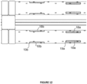
- Figures 12 and 13 show an alternative embodiment of the conveyor in which the contact portions 18a of the first weighing means 16a do not overlap the contact portions 18b of the second weighing means 16b (in the direction of conveyor travel).
- a leading edge 19a of the contact portion 18a of the first weighing means is spaced apart from the contact portion 19b of the contact portion 18b of second weighing means (in the direction of travel of the conveyor) by a distance substantially equal to a distance between the leading edge of adjacent first and second carrier portions 2a, 2b, such that the bearing surfaces of the first carrier means 2a contact the weighing means contact portions 18a of the first weighing means at substantially the same time as the bearing surfaces of the second carrier means 2b contact the weighing means contact portions 18b of the second weighing means. In this way vibration is reduced during the weighing process.
- the article to be conveyed may be elongate, and may extend over three or more carrier portions.
- one or more carrier portions between the carrier portion supporting the front of the article and the carrier portion supporting the rear of the article may be moved to a discharge position prior to the bearing surfaces of the carrier portions contacting the relevant weighing means.
- the weight of the article may be determined more accurately.
- a vision system for example as is used to inspect produce, may be used to determine which carrier portions to move to the discharge position.
- two directly opposite carrier portions 2 may be omitted, leaving only one carrier portion 2 on each side of the mounting portion 1.
- the orientation of every second article carrier may need to be reversed in order to ensure that bearing means from only one article carrier at a time are in contact with each weighing means contact portion.
- the article carrier 100 shown in Figures 1-8 has a twofold rotational symmetry B, that is, the shape is identical if rotated about a central axis of symmetry by 180°. This means that the article carrier 100 can be attached to the conveyor in either of two orientations. However, this is not essential, and in some embodiments the opposed carrier portions 2 may be of the same type (that is, they may both be first carrier portions 2a or second carrier portions 2b).
- FIG. 14 an embodiment of the invention is shown with an alternative design of article carrier, generally referenced by arrow 101.
- the article carriers are similar to those shown in International PCT Publication No WO2004067417 .
- two types of article carrier 101a, 101b are mounted to the conveyor (not shown) alternately.
- Each article carrier 101 is provided with bearing means comprising four spaced apart feet.
- the feet 20a from a first set of article carriers 101a are positioned to contact the weighing means contact portions 21a of a first weighing means, but not the weighing means contact portions 21b of a second weighing means, and the feet 20b of the second set of article carriers 101b are positioned to contact the weighing means contact portions 21b of the second weighing means, but not the weighing means contact portions 21a of the first weighing means.
Landscapes
- Engineering & Computer Science (AREA)
- Mechanical Engineering (AREA)
- Chain Conveyers (AREA)
- Discharge Of Articles From Conveyors (AREA)
- Sorting Of Articles (AREA)
- Handcart (AREA)
- Framework For Endless Conveyors (AREA)
Claims (14)
- Support d'articles (100) destiné à être utilisé dans un système de classement de fruits ou de légumes, le support d'articles (100) comprenant une partie de montage (1) conçue pour être connectée à un transporteur le long d'un axe de transport (A) du support d'articles (100),le support d'articles (100) comprenant en outre une première (2a) et une seconde (2b) parties de support connectées à la partie de montage (1) et configurées pour permettre la pesée d'un ou de plusieurs articles (C) transportés, en cours d'utilisation, par les parties de support (2) ;dans lequel la première partie de support (2a) comprend une première surface d'appui (17a) et une deuxième surface d'appui (17b), et la seconde partie de support (2b) comprend une troisième surface d'appui (17c) et une quatrième surface d'appui espacée (17d) ;dans lequel une distance entre l'axe de transporteur (A) du support d'articles (100) et n'importe quel point sur l'une des surfaces d'appui (17), mesurée orthogonalement à l'axe de transport (A) du support d'articles (100), est différente d'une distance entre l'axe de transport (A) du support d'articles (100) et n'importe quel point sur l'une quelconque des autres surfaces d'appui (17), mesurée orthogonalement à l'axe de transport (A) du support d'articles (100) ;caractérisé en ce queles première (2a) et seconde (2b) parties de support sont connectées à la partie de montage (1) du même côté de l'axe de transport (A) du support d'articles (100), etdans lequel chaque partie de support (2) peut être déplacée d'une position de chariot à une position de déchargement indépendamment de chaque autre partie de support (2).
- Support d'articles selon la revendication 1, dans lequel les première (17a) et deuxième (17b) surfaces d'appui sont espacées.
- Support d'articles selon la revendication 1, dans lequel les première (17a) et deuxième (17b) surfaces d'appui sont sensiblement contiguës.
- Support d'articles selon l'une quelconque des revendications précédentes, dans lequel l'axe de transport (A) du support d'articles (100) se trouve sur un plan central du support d'articles (100).
- Support d'articles selon l'une quelconque des revendications précédentes, dans lequel le support d'articles (100) est sensiblement symétrique par rapport à un plan central qui coupe l'axe de transport (A) du support d'articles (100).
- Support d'articles selon l'une quelconque des revendications 1 à 3, dans lequel le support d'articles (100) a un axe de symétrie de rotation double (B).
- Support d'articles selon la revendication 6, dans lequel l'axe de symétrie de rotation (B) coupe l'axe de transport (A) du support d'articles (100).
- Support d'articles selon l'une quelconque des revendications précédentes comprenant un élément de connexion (3) connecté de manière rotative à la partie de montage (1) et rotatif par rapport à la partie de montage (1) autour d'un premier axe de rotation (R1), dans lequel la première partie de support (2a) est connectée de manière rotative à l'élément de connexion (3) et peut tourner par rapport à l'élément de connexion (3) autour d'un second axe de rotation (R2) qui est espacé du premier axe de rotation (R1) ;la partie de support (2) comprenant une partie de limitation de rotation (11) configurée pour venir en butée contre l'élément de connexion (3) afin de limiter la rotation de la partie de support (100) par rapport à l'élément de connexion (3) ;le support d'articles (100) comprenant en outre un moyen de verrouillage d'élément de connexion (4) conçu pour se déplacer entre une première position dans lequel le moyen de verrouillage d'élément de connexion (4) est en prise avec l'élément de connexion (3) et maintient l'élément de connexion (3) dans la position de chariot, et une seconde position dans lequel le moyen de verrouillage d'élément de connexion (4) est dégagé de l'élément de connexion (3), permettant ainsi à l'élément de connexion (3) de se déplacer vers la position de déchargement.
- Support d'articles selon la revendication 8, dans lequel le moyen de verrouillage d'élément de connexion (4) comprend un élément de moyen de verrouillage (5) qui est connecté de manière rotative à la partie de montage (1).
- Support d'articles selon la revendication 9, dans lequel une première extrémité de l'élément de moyen de verrouillage (5) est pourvue d'une partie de mise en prise (6) qui vient en prise avec une surface de support (7) du premier élément de connexion (3) .
- Support d'articles selon la revendication 10, dans lequel la surface de support (7) est définie par une paroi (8) d'un évidement (9) prévu au niveau d'une extrémité du premier élément de connexion (3).
- Support d'articles selon la revendication 11, dans lequel une seconde extrémité de l'élément de moyen de verrouillage (5) comprend une partie de déclenchement (10) et le mouvement de la partie de déclenchement (10) à l'écart de la partie de montage (1) déplace le moyen de verrouillage (4) de la première position vers la seconde position.
- Support d'articles selon l'une quelconque des revendications précédentes, dans lequel les première (2a) et seconde (2b) parties de support sont en forme de doigts allongés.
- Système de transport pour un système de classement comprenant un transporteur,
caractérisé par
comprenant au moins un support d'articles (100) selon l'une quelconque des revendications 1 à 13 connecté au transporteur.
Applications Claiming Priority (2)
| Application Number | Priority Date | Filing Date | Title |
|---|---|---|---|
| NZ72180116 | 2016-07-01 | ||
| PCT/NZ2017/050090 WO2018004362A1 (fr) | 2016-07-01 | 2017-06-30 | Système de transport et supports d'articles associés |
Publications (3)
| Publication Number | Publication Date |
|---|---|
| EP3478607A1 EP3478607A1 (fr) | 2019-05-08 |
| EP3478607A4 EP3478607A4 (fr) | 2020-03-11 |
| EP3478607B1 true EP3478607B1 (fr) | 2024-08-07 |
Family
ID=60786480
Family Applications (1)
| Application Number | Title | Priority Date | Filing Date |
|---|---|---|---|
| EP17820613.2A Active EP3478607B1 (fr) | 2016-07-01 | 2017-06-30 | Système de transport et supports d'articles associés |
Country Status (7)
| Country | Link |
|---|---|
| US (1) | US10933446B2 (fr) |
| EP (1) | EP3478607B1 (fr) |
| CN (1) | CN110023211B (fr) |
| AU (1) | AU2017287794A1 (fr) |
| CL (1) | CL2018003833A1 (fr) |
| WO (1) | WO2018004362A1 (fr) |
| ZA (1) | ZA201900155B (fr) |
Families Citing this family (6)
| Publication number | Priority date | Publication date | Assignee | Title |
|---|---|---|---|---|
| CN108325865B (zh) * | 2018-03-12 | 2024-03-19 | 浙江大学 | 用于果蔬分选的单链双托式果杯装置 |
| CN109225922B (zh) * | 2018-08-10 | 2020-08-28 | 北京农业智能装备技术研究中心 | 西瓜自动称重和内部质量检测托盘式传输分级装置 |
| CN109248866B (zh) * | 2018-08-10 | 2020-05-22 | 北京农业智能装备技术研究中心 | 一种大尺寸水果自动称重和内部质量检测托盘式分级装置 |
| CN109719041B (zh) * | 2019-02-28 | 2024-08-09 | 广东力生智能有限公司 | 分拣机台车翻盘机构 |
| US11529653B2 (en) | 2021-01-11 | 2022-12-20 | Durand-Wayland, Inc. | Produce sorting systems and methods |
| US20250042673A1 (en) * | 2021-12-10 | 2025-02-06 | Kennedy Technologies Limited | Apparatus and methods relating to sorting objects |
Family Cites Families (15)
| Publication number | Priority date | Publication date | Assignee | Title |
|---|---|---|---|---|
| US4403669A (en) * | 1982-01-18 | 1983-09-13 | Eshet Eilon | Apparatus for weighing continuously-moving articles particularly useful for grading produce |
| US4413690A (en) * | 1982-03-12 | 1983-11-08 | Fmc Corporation | Weighing cup |
| US4711344A (en) | 1986-01-09 | 1987-12-08 | Altenpohl Paul J | Accurate weight sorting arrangement for poultry conveyor system |
| US4660665A (en) * | 1986-03-07 | 1987-04-28 | Powell Jr Harry | Accurate weight sizing |
| NL8702259A (nl) | 1986-09-25 | 1988-04-18 | Autosystems Ltd | Transportinrichting. |
| FR2670691B1 (fr) | 1990-12-19 | 1993-03-19 | Materiel Arboriculture | Dispositif de convoyage de produits, notamment de fruits, adapte pour effectuer un triage desdits produits en fonction de criteres de selection predetermines. |
| ATE184855T1 (de) * | 1992-12-22 | 1999-10-15 | Horticultural Automation Ltd | Einrichtung zur kalibrierung von artikeln |
| US6092640A (en) * | 1992-12-22 | 2000-07-25 | Horticultural Automation Limited | Article grading apparatus |
| US6079542A (en) * | 1998-02-20 | 2000-06-27 | Agri-Tech, Inc. | Object sorter and sizer |
| ES1043355Y (es) * | 1999-06-29 | 2000-05-01 | Morigi Romana Amaducci | Transportador para seleccion de fruta mejorado. |
| NZ523931A (en) | 2003-01-31 | 2005-06-24 | Anzpac Systems Ltd | Article carrier for a grading apparatus |
| CN201313096Y (zh) * | 2008-09-11 | 2009-09-23 | 杭州行地集团有限公司 | 水果分级机用水果输送翻转装置 |
| US8714365B2 (en) | 2009-01-23 | 2014-05-06 | Maf Agrobotic | Fruit handling equipment |
| JP2015533649A (ja) * | 2012-11-08 | 2015-11-26 | コンパック テクノロジーズ リミティド | 格付け装置のための物品搬送器 |
| CN103056115A (zh) * | 2013-01-22 | 2013-04-24 | 苏州博田自动化技术有限公司 | 电子式果蔬分选称台 |
-
2017
- 2017-06-30 EP EP17820613.2A patent/EP3478607B1/fr active Active
- 2017-06-30 WO PCT/NZ2017/050090 patent/WO2018004362A1/fr not_active Ceased
- 2017-06-30 CN CN201780053083.2A patent/CN110023211B/zh active Active
- 2017-06-30 US US16/313,256 patent/US10933446B2/en active Active
- 2017-06-30 AU AU2017287794A patent/AU2017287794A1/en not_active Abandoned
-
2018
- 2018-12-27 CL CL2018003833A patent/CL2018003833A1/es unknown
-
2019
- 2019-01-09 ZA ZA2019/00155A patent/ZA201900155B/en unknown
Also Published As
| Publication number | Publication date |
|---|---|
| EP3478607A4 (fr) | 2020-03-11 |
| US10933446B2 (en) | 2021-03-02 |
| CN110023211B (zh) | 2021-06-29 |
| US20190151903A1 (en) | 2019-05-23 |
| NZ749828A (en) | 2025-02-28 |
| CL2018003833A1 (es) | 2019-06-21 |
| AU2017287794A1 (en) | 2019-02-14 |
| WO2018004362A1 (fr) | 2018-01-04 |
| CN110023211A (zh) | 2019-07-16 |
| EP3478607A1 (fr) | 2019-05-08 |
| ZA201900155B (en) | 2021-04-28 |
Similar Documents
| Publication | Publication Date | Title |
|---|---|---|
| EP3478607B1 (fr) | Système de transport et supports d'articles associés | |
| CN104981419B (zh) | 用于分选设备的物品托架 | |
| AU2015254679B2 (en) | Device for unilateral analysis of products by turning and automatic sorting and conveying device incorporating same | |
| JP6834082B2 (ja) | 多列搬送コンベアおよび選別装置 | |
| TW202132189A (zh) | 搬運裝置 | |
| US20170096303A1 (en) | Conveyor belt idler systems | |
| JP6038624B2 (ja) | 重量選別装置 | |
| JP5921258B2 (ja) | 重量選別装置 | |
| US7060913B2 (en) | Measuring apparatus | |
| JP2012180161A (ja) | ワークの搬送装置 | |
| ES2986052T3 (es) | Sistema transportador y portadores de artículos para el mismo | |
| CN103204371A (zh) | 工件搬运装置 | |
| US7341140B1 (en) | Off-loading conveyor of produce | |
| JP2005239426A (ja) | 供給コンベヤ | |
| JP6626022B2 (ja) | 計量装置 | |
| JP6049400B2 (ja) | 計量装置 | |
| JP3546107B2 (ja) | 搬送計量装置 | |
| NZ617389B2 (en) | Article carrier for a grading apparatus | |
| JP3626848B2 (ja) | 農産物の移載装置 | |
| JP2016217717A (ja) | 重量選別機 | |
| NZ726410B2 (en) | Device for unilateral analysis of products by turning and automatic sorting and conveying device incorporating same | |
| JPS63240977A (ja) | 選果装置 | |
| EP2586734A1 (fr) | Elément de support pour le tri de fruits ou légumes | |
| JPH10194443A (ja) | 農産物の移載装置 |
Legal Events
| Date | Code | Title | Description |
|---|---|---|---|
| STAA | Information on the status of an ep patent application or granted ep patent |
Free format text: STATUS: THE INTERNATIONAL PUBLICATION HAS BEEN MADE |
|
| PUAI | Public reference made under article 153(3) epc to a published international application that has entered the european phase |
Free format text: ORIGINAL CODE: 0009012 |
|
| STAA | Information on the status of an ep patent application or granted ep patent |
Free format text: STATUS: REQUEST FOR EXAMINATION WAS MADE |
|
| 17P | Request for examination filed |
Effective date: 20190131 |
|
| AK | Designated contracting states |
Kind code of ref document: A1 Designated state(s): AL AT BE BG CH CY CZ DE DK EE ES FI FR GB GR HR HU IE IS IT LI LT LU LV MC MK MT NL NO PL PT RO RS SE SI SK SM TR |
|
| AX | Request for extension of the european patent |
Extension state: BA ME |
|
| RAP1 | Party data changed (applicant data changed or rights of an application transferred) |
Owner name: COMPAC TECHNOLOGIES LIMITED |
|
| DAV | Request for validation of the european patent (deleted) | ||
| DAX | Request for extension of the european patent (deleted) | ||
| A4 | Supplementary search report drawn up and despatched |
Effective date: 20200212 |
|
| RIC1 | Information provided on ipc code assigned before grant |
Ipc: B65G 17/16 20060101ALI20200206BHEP Ipc: B07C 5/22 20060101ALI20200206BHEP Ipc: B65G 47/40 20060101AFI20200206BHEP Ipc: B07C 5/16 20060101ALI20200206BHEP Ipc: B65G 47/96 20060101ALI20200206BHEP |
|
| STAA | Information on the status of an ep patent application or granted ep patent |
Free format text: STATUS: EXAMINATION IS IN PROGRESS |
|
| 17Q | First examination report despatched |
Effective date: 20210527 |
|
| P01 | Opt-out of the competence of the unified patent court (upc) registered |
Effective date: 20230523 |
|
| REG | Reference to a national code |
Ref legal event code: R079 Ref country code: DE Ref legal event code: R079 Ref document number: 602017083933 Country of ref document: DE Free format text: PREVIOUS MAIN CLASS: B65G0047400000 Ipc: B07C0005360000 |
|
| GRAP | Despatch of communication of intention to grant a patent |
Free format text: ORIGINAL CODE: EPIDOSNIGR1 |
|
| STAA | Information on the status of an ep patent application or granted ep patent |
Free format text: STATUS: GRANT OF PATENT IS INTENDED |
|
| RIC1 | Information provided on ipc code assigned before grant |
Ipc: B65G 17/16 20060101ALI20240215BHEP Ipc: B65G 47/96 20060101ALI20240215BHEP Ipc: B07C 5/16 20060101ALI20240215BHEP Ipc: B07C 5/36 20060101AFI20240215BHEP |
|
| INTG | Intention to grant announced |
Effective date: 20240301 |
|
| GRAS | Grant fee paid |
Free format text: ORIGINAL CODE: EPIDOSNIGR3 |
|
| GRAA | (expected) grant |
Free format text: ORIGINAL CODE: 0009210 |
|
| STAA | Information on the status of an ep patent application or granted ep patent |
Free format text: STATUS: THE PATENT HAS BEEN GRANTED |
|
| AK | Designated contracting states |
Kind code of ref document: B1 Designated state(s): AL AT BE BG CH CY CZ DE DK EE ES FI FR GB GR HR HU IE IS IT LI LT LU LV MC MK MT NL NO PL PT RO RS SE SI SK SM TR |
|
| REG | Reference to a national code |
Ref country code: GB Ref legal event code: FG4D |
|
| REG | Reference to a national code |
Ref country code: CH Ref legal event code: EP |
|
| REG | Reference to a national code |
Ref country code: IE Ref legal event code: FG4D |
|
| REG | Reference to a national code |
Ref country code: DE Ref legal event code: R096 Ref document number: 602017083933 Country of ref document: DE |
|
| REG | Reference to a national code |
Ref country code: ES Ref legal event code: FG2A Ref document number: 2986052 Country of ref document: ES Kind code of ref document: T3 Effective date: 20241108 |
|
| REG | Reference to a national code |
Ref country code: LT Ref legal event code: MG9D |
|
| REG | Reference to a national code |
Ref country code: NL Ref legal event code: MP Effective date: 20240807 |
|
| PG25 | Lapsed in a contracting state [announced via postgrant information from national office to epo] |
Ref country code: NO Free format text: LAPSE BECAUSE OF FAILURE TO SUBMIT A TRANSLATION OF THE DESCRIPTION OR TO PAY THE FEE WITHIN THE PRESCRIBED TIME-LIMIT Effective date: 20241107 |
|
| REG | Reference to a national code |
Ref country code: AT Ref legal event code: MK05 Ref document number: 1710376 Country of ref document: AT Kind code of ref document: T Effective date: 20240807 |
|
| PG25 | Lapsed in a contracting state [announced via postgrant information from national office to epo] |
Ref country code: PT Free format text: LAPSE BECAUSE OF FAILURE TO SUBMIT A TRANSLATION OF THE DESCRIPTION OR TO PAY THE FEE WITHIN THE PRESCRIBED TIME-LIMIT Effective date: 20241209 Ref country code: NL Free format text: LAPSE BECAUSE OF FAILURE TO SUBMIT A TRANSLATION OF THE DESCRIPTION OR TO PAY THE FEE WITHIN THE PRESCRIBED TIME-LIMIT Effective date: 20240807 Ref country code: FI Free format text: LAPSE BECAUSE OF FAILURE TO SUBMIT A TRANSLATION OF THE DESCRIPTION OR TO PAY THE FEE WITHIN THE PRESCRIBED TIME-LIMIT Effective date: 20240807 Ref country code: GR Free format text: LAPSE BECAUSE OF FAILURE TO SUBMIT A TRANSLATION OF THE DESCRIPTION OR TO PAY THE FEE WITHIN THE PRESCRIBED TIME-LIMIT Effective date: 20241108 Ref country code: PL Free format text: LAPSE BECAUSE OF FAILURE TO SUBMIT A TRANSLATION OF THE DESCRIPTION OR TO PAY THE FEE WITHIN THE PRESCRIBED TIME-LIMIT Effective date: 20240807 |
|
| PG25 | Lapsed in a contracting state [announced via postgrant information from national office to epo] |
Ref country code: BG Free format text: LAPSE BECAUSE OF FAILURE TO SUBMIT A TRANSLATION OF THE DESCRIPTION OR TO PAY THE FEE WITHIN THE PRESCRIBED TIME-LIMIT Effective date: 20240807 |
|
| PG25 | Lapsed in a contracting state [announced via postgrant information from national office to epo] |
Ref country code: LV Free format text: LAPSE BECAUSE OF FAILURE TO SUBMIT A TRANSLATION OF THE DESCRIPTION OR TO PAY THE FEE WITHIN THE PRESCRIBED TIME-LIMIT Effective date: 20240807 |
|
| PG25 | Lapsed in a contracting state [announced via postgrant information from national office to epo] |
Ref country code: AT Free format text: LAPSE BECAUSE OF FAILURE TO SUBMIT A TRANSLATION OF THE DESCRIPTION OR TO PAY THE FEE WITHIN THE PRESCRIBED TIME-LIMIT Effective date: 20240807 Ref country code: IS Free format text: LAPSE BECAUSE OF FAILURE TO SUBMIT A TRANSLATION OF THE DESCRIPTION OR TO PAY THE FEE WITHIN THE PRESCRIBED TIME-LIMIT Effective date: 20241207 |
|
| PG25 | Lapsed in a contracting state [announced via postgrant information from national office to epo] |
Ref country code: HR Free format text: LAPSE BECAUSE OF FAILURE TO SUBMIT A TRANSLATION OF THE DESCRIPTION OR TO PAY THE FEE WITHIN THE PRESCRIBED TIME-LIMIT Effective date: 20240807 |
|
| PG25 | Lapsed in a contracting state [announced via postgrant information from national office to epo] |
Ref country code: RS Free format text: LAPSE BECAUSE OF FAILURE TO SUBMIT A TRANSLATION OF THE DESCRIPTION OR TO PAY THE FEE WITHIN THE PRESCRIBED TIME-LIMIT Effective date: 20241107 |
|
| PG25 | Lapsed in a contracting state [announced via postgrant information from national office to epo] |
Ref country code: RS Free format text: LAPSE BECAUSE OF FAILURE TO SUBMIT A TRANSLATION OF THE DESCRIPTION OR TO PAY THE FEE WITHIN THE PRESCRIBED TIME-LIMIT Effective date: 20241107 Ref country code: PT Free format text: LAPSE BECAUSE OF FAILURE TO SUBMIT A TRANSLATION OF THE DESCRIPTION OR TO PAY THE FEE WITHIN THE PRESCRIBED TIME-LIMIT Effective date: 20241209 Ref country code: PL Free format text: LAPSE BECAUSE OF FAILURE TO SUBMIT A TRANSLATION OF THE DESCRIPTION OR TO PAY THE FEE WITHIN THE PRESCRIBED TIME-LIMIT Effective date: 20240807 Ref country code: NO Free format text: LAPSE BECAUSE OF FAILURE TO SUBMIT A TRANSLATION OF THE DESCRIPTION OR TO PAY THE FEE WITHIN THE PRESCRIBED TIME-LIMIT Effective date: 20241107 Ref country code: NL Free format text: LAPSE BECAUSE OF FAILURE TO SUBMIT A TRANSLATION OF THE DESCRIPTION OR TO PAY THE FEE WITHIN THE PRESCRIBED TIME-LIMIT Effective date: 20240807 Ref country code: LV Free format text: LAPSE BECAUSE OF FAILURE TO SUBMIT A TRANSLATION OF THE DESCRIPTION OR TO PAY THE FEE WITHIN THE PRESCRIBED TIME-LIMIT Effective date: 20240807 Ref country code: IS Free format text: LAPSE BECAUSE OF FAILURE TO SUBMIT A TRANSLATION OF THE DESCRIPTION OR TO PAY THE FEE WITHIN THE PRESCRIBED TIME-LIMIT Effective date: 20241207 Ref country code: HR Free format text: LAPSE BECAUSE OF FAILURE TO SUBMIT A TRANSLATION OF THE DESCRIPTION OR TO PAY THE FEE WITHIN THE PRESCRIBED TIME-LIMIT Effective date: 20240807 Ref country code: GR Free format text: LAPSE BECAUSE OF FAILURE TO SUBMIT A TRANSLATION OF THE DESCRIPTION OR TO PAY THE FEE WITHIN THE PRESCRIBED TIME-LIMIT Effective date: 20241108 Ref country code: FI Free format text: LAPSE BECAUSE OF FAILURE TO SUBMIT A TRANSLATION OF THE DESCRIPTION OR TO PAY THE FEE WITHIN THE PRESCRIBED TIME-LIMIT Effective date: 20240807 Ref country code: BG Free format text: LAPSE BECAUSE OF FAILURE TO SUBMIT A TRANSLATION OF THE DESCRIPTION OR TO PAY THE FEE WITHIN THE PRESCRIBED TIME-LIMIT Effective date: 20240807 Ref country code: AT Free format text: LAPSE BECAUSE OF FAILURE TO SUBMIT A TRANSLATION OF THE DESCRIPTION OR TO PAY THE FEE WITHIN THE PRESCRIBED TIME-LIMIT Effective date: 20240807 |
|
| PG25 | Lapsed in a contracting state [announced via postgrant information from national office to epo] |
Ref country code: SM Free format text: LAPSE BECAUSE OF FAILURE TO SUBMIT A TRANSLATION OF THE DESCRIPTION OR TO PAY THE FEE WITHIN THE PRESCRIBED TIME-LIMIT Effective date: 20240807 Ref country code: RO Free format text: LAPSE BECAUSE OF FAILURE TO SUBMIT A TRANSLATION OF THE DESCRIPTION OR TO PAY THE FEE WITHIN THE PRESCRIBED TIME-LIMIT Effective date: 20240807 Ref country code: DK Free format text: LAPSE BECAUSE OF FAILURE TO SUBMIT A TRANSLATION OF THE DESCRIPTION OR TO PAY THE FEE WITHIN THE PRESCRIBED TIME-LIMIT Effective date: 20240807 |
|
| PG25 | Lapsed in a contracting state [announced via postgrant information from national office to epo] |
Ref country code: EE Free format text: LAPSE BECAUSE OF FAILURE TO SUBMIT A TRANSLATION OF THE DESCRIPTION OR TO PAY THE FEE WITHIN THE PRESCRIBED TIME-LIMIT Effective date: 20240807 |
|
| PG25 | Lapsed in a contracting state [announced via postgrant information from national office to epo] |
Ref country code: CZ Free format text: LAPSE BECAUSE OF FAILURE TO SUBMIT A TRANSLATION OF THE DESCRIPTION OR TO PAY THE FEE WITHIN THE PRESCRIBED TIME-LIMIT Effective date: 20240807 |
|
| PG25 | Lapsed in a contracting state [announced via postgrant information from national office to epo] |
Ref country code: SK Free format text: LAPSE BECAUSE OF FAILURE TO SUBMIT A TRANSLATION OF THE DESCRIPTION OR TO PAY THE FEE WITHIN THE PRESCRIBED TIME-LIMIT Effective date: 20240807 |
|
| REG | Reference to a national code |
Ref country code: DE Ref legal event code: R097 Ref document number: 602017083933 Country of ref document: DE |
|
| PLBE | No opposition filed within time limit |
Free format text: ORIGINAL CODE: 0009261 |
|
| STAA | Information on the status of an ep patent application or granted ep patent |
Free format text: STATUS: NO OPPOSITION FILED WITHIN TIME LIMIT |
|
| 26N | No opposition filed |
Effective date: 20250508 |
|
| PG25 | Lapsed in a contracting state [announced via postgrant information from national office to epo] |
Ref country code: SE Free format text: LAPSE BECAUSE OF FAILURE TO SUBMIT A TRANSLATION OF THE DESCRIPTION OR TO PAY THE FEE WITHIN THE PRESCRIBED TIME-LIMIT Effective date: 20240807 |
|
| REG | Reference to a national code |
Ref country code: DE Ref legal event code: R119 Ref document number: 602017083933 Country of ref document: DE |
|
| REG | Reference to a national code |
Ref country code: CH Ref legal event code: H13 Free format text: ST27 STATUS EVENT CODE: U-0-0-H10-H13 (AS PROVIDED BY THE NATIONAL OFFICE) Effective date: 20260127 |
|
| PG25 | Lapsed in a contracting state [announced via postgrant information from national office to epo] |
Ref country code: IT Free format text: LAPSE BECAUSE OF FAILURE TO SUBMIT A TRANSLATION OF THE DESCRIPTION OR TO PAY THE FEE WITHIN THE PRESCRIBED TIME-LIMIT Effective date: 20240807 |
|
| PG25 | Lapsed in a contracting state [announced via postgrant information from national office to epo] |
Ref country code: MC Free format text: LAPSE BECAUSE OF FAILURE TO SUBMIT A TRANSLATION OF THE DESCRIPTION OR TO PAY THE FEE WITHIN THE PRESCRIBED TIME-LIMIT Effective date: 20240807 |
|
| PG25 | Lapsed in a contracting state [announced via postgrant information from national office to epo] |
Ref country code: LU Free format text: LAPSE BECAUSE OF NON-PAYMENT OF DUE FEES Effective date: 20250630 |
|
| GBPC | Gb: european patent ceased through non-payment of renewal fee |
Effective date: 20250630 |
|
| REG | Reference to a national code |
Ref country code: BE Ref legal event code: MM Effective date: 20250630 |
|
| PG25 | Lapsed in a contracting state [announced via postgrant information from national office to epo] |
Ref country code: GB Free format text: LAPSE BECAUSE OF NON-PAYMENT OF DUE FEES Effective date: 20250630 |
|
| PG25 | Lapsed in a contracting state [announced via postgrant information from national office to epo] |
Ref country code: IE Free format text: LAPSE BECAUSE OF NON-PAYMENT OF DUE FEES Effective date: 20250630 Ref country code: DE Free format text: LAPSE BECAUSE OF NON-PAYMENT OF DUE FEES Effective date: 20260101 |
|
| PG25 | Lapsed in a contracting state [announced via postgrant information from national office to epo] |
Ref country code: BE Free format text: LAPSE BECAUSE OF NON-PAYMENT OF DUE FEES Effective date: 20250630 |
|
| PG25 | Lapsed in a contracting state [announced via postgrant information from national office to epo] |
Ref country code: FR Free format text: LAPSE BECAUSE OF NON-PAYMENT OF DUE FEES Effective date: 20250630 |