EP3479356B1 - Système et procédé d'identification d'une pose de caméra d'une caméra orientée vers l'avant dans un véhicule - Google Patents
Système et procédé d'identification d'une pose de caméra d'une caméra orientée vers l'avant dans un véhicule Download PDFInfo
- Publication number
- EP3479356B1 EP3479356B1 EP17818744.9A EP17818744A EP3479356B1 EP 3479356 B1 EP3479356 B1 EP 3479356B1 EP 17818744 A EP17818744 A EP 17818744A EP 3479356 B1 EP3479356 B1 EP 3479356B1
- Authority
- EP
- European Patent Office
- Prior art keywords
- vehicle
- driver
- facing camera
- camera
- images
- Prior art date
- Legal status (The legal status is an assumption and is not a legal conclusion. Google has not performed a legal analysis and makes no representation as to the accuracy of the status listed.)
- Active
Links
Images


Classifications
-
- G—PHYSICS
- G06—COMPUTING OR CALCULATING; COUNTING
- G06T—IMAGE DATA PROCESSING OR GENERATION, IN GENERAL
- G06T7/00—Image analysis
- G06T7/80—Analysis of captured images to determine intrinsic or extrinsic camera parameters, i.e. camera calibration
-
- G—PHYSICS
- G06—COMPUTING OR CALCULATING; COUNTING
- G06T—IMAGE DATA PROCESSING OR GENERATION, IN GENERAL
- G06T7/00—Image analysis
- G06T7/60—Analysis of geometric attributes
-
- G—PHYSICS
- G06—COMPUTING OR CALCULATING; COUNTING
- G06T—IMAGE DATA PROCESSING OR GENERATION, IN GENERAL
- G06T7/00—Image analysis
- G06T7/70—Determining position or orientation of objects or cameras
- G06T7/73—Determining position or orientation of objects or cameras using feature-based methods
- G06T7/74—Determining position or orientation of objects or cameras using feature-based methods involving reference images or patches
-
- G—PHYSICS
- G06—COMPUTING OR CALCULATING; COUNTING
- G06V—IMAGE OR VIDEO RECOGNITION OR UNDERSTANDING
- G06V20/00—Scenes; Scene-specific elements
- G06V20/50—Context or environment of the image
- G06V20/59—Context or environment of the image inside of a vehicle, e.g. relating to seat occupancy, driver state or inner lighting conditions
- G06V20/597—Recognising the driver's state or behaviour, e.g. attention or drowsiness
-
- G—PHYSICS
- G06—COMPUTING OR CALCULATING; COUNTING
- G06V—IMAGE OR VIDEO RECOGNITION OR UNDERSTANDING
- G06V40/00—Recognition of biometric, human-related or animal-related patterns in image or video data
- G06V40/10—Human or animal bodies, e.g. vehicle occupants or pedestrians; Body parts, e.g. hands
- G06V40/16—Human faces, e.g. facial parts, sketches or expressions
- G06V40/161—Detection; Localisation; Normalisation
-
- G—PHYSICS
- G06—COMPUTING OR CALCULATING; COUNTING
- G06V—IMAGE OR VIDEO RECOGNITION OR UNDERSTANDING
- G06V40/00—Recognition of biometric, human-related or animal-related patterns in image or video data
- G06V40/10—Human or animal bodies, e.g. vehicle occupants or pedestrians; Body parts, e.g. hands
- G06V40/18—Eye characteristics, e.g. of the iris
- G06V40/19—Sensors therefor
-
- H—ELECTRICITY
- H04—ELECTRIC COMMUNICATION TECHNIQUE
- H04N—PICTORIAL COMMUNICATION, e.g. TELEVISION
- H04N23/00—Cameras or camera modules comprising electronic image sensors; Control thereof
- H04N23/90—Arrangement of cameras or camera modules, e.g. multiple cameras in TV studios or sports stadiums
-
- G—PHYSICS
- G06—COMPUTING OR CALCULATING; COUNTING
- G06T—IMAGE DATA PROCESSING OR GENERATION, IN GENERAL
- G06T2207/00—Indexing scheme for image analysis or image enhancement
- G06T2207/20—Special algorithmic details
- G06T2207/20081—Training; Learning
-
- G—PHYSICS
- G06—COMPUTING OR CALCULATING; COUNTING
- G06T—IMAGE DATA PROCESSING OR GENERATION, IN GENERAL
- G06T2207/00—Indexing scheme for image analysis or image enhancement
- G06T2207/30—Subject of image; Context of image processing
- G06T2207/30196—Human being; Person
- G06T2207/30201—Face
-
- G—PHYSICS
- G06—COMPUTING OR CALCULATING; COUNTING
- G06T—IMAGE DATA PROCESSING OR GENERATION, IN GENERAL
- G06T2207/00—Indexing scheme for image analysis or image enhancement
- G06T2207/30—Subject of image; Context of image processing
- G06T2207/30244—Camera pose
-
- G—PHYSICS
- G06—COMPUTING OR CALCULATING; COUNTING
- G06T—IMAGE DATA PROCESSING OR GENERATION, IN GENERAL
- G06T2207/00—Indexing scheme for image analysis or image enhancement
- G06T2207/30—Subject of image; Context of image processing
- G06T2207/30248—Vehicle exterior or interior
- G06T2207/30252—Vehicle exterior; Vicinity of vehicle
- G06T2207/30256—Lane; Road marking
-
- G—PHYSICS
- G06—COMPUTING OR CALCULATING; COUNTING
- G06T—IMAGE DATA PROCESSING OR GENERATION, IN GENERAL
- G06T2207/00—Indexing scheme for image analysis or image enhancement
- G06T2207/30—Subject of image; Context of image processing
- G06T2207/30248—Vehicle exterior or interior
- G06T2207/30268—Vehicle interior
-
- G—PHYSICS
- G06—COMPUTING OR CALCULATING; COUNTING
- G06V—IMAGE OR VIDEO RECOGNITION OR UNDERSTANDING
- G06V10/00—Arrangements for image or video recognition or understanding
- G06V10/20—Image preprocessing
- G06V10/24—Aligning, centring, orientation detection or correction of the image
- G06V10/245—Aligning, centring, orientation detection or correction of the image by locating a pattern; Special marks for positioning
Definitions
- the present invention relates to camera monitoring systems and in particular to a system and method for identifying a camera pose of a forward facing camera in a vehicle.
- Embodiments of the invention have been particularly developed for driver monitoring systems in vehicles. While some embodiments will be described herein with particular reference to that application, it will be appreciated that the invention is not limited to such a field of use, and is applicable in broader contexts.
- step d) includes determining a location of a road lane in front of the vehicle by processing the images captured by the forward facing camera. In one embodiment step d) includes determining an angle of gradient of the vehicle. In one embodiment step d) includes identifying the position of the driver's head within the vehicle cabin. The position of the driver's head may be identified by performing facial recognition on the driver and loading physiological data. In one embodiment a seat height, angle and/or lateral position of the driver's seat is determined.
- step b) includes:
- step b)i. includes
- a vehicle monitoring system including: one or more driver facing cameras (102) positioned to capture images of a vehicle driver's face in the driver facing camera (102) frame of reference during normal operation of the vehicle (106) when the driver is seated in the driver's seat and operating the vehicle; a forward facing camera (101) positioned to capture images of a forward road scene in front of the vehicle in the forward facing camera (101) frame of reference during normal operation of the vehicle (106); a computer processor configured to perform a method according to the first aspect.
- a non-transitive carrier medium carrying computer executable code that, when executed on a processor, causes the processor to perform a method according to the first aspect.
- the specific camera locations are exemplary only and it will be appreciated that more or less cameras can be incorporated at other locations within or outside vehicle 106 to monitor the driver, the forward road scene or other views in or around the vehicle.
- Other exemplary camera locations of cameras include a rearview mirror, rear bumper, front bumper, vehicle roof and bonnet/hood.
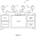
- System 100 includes a central processing unit 300 including a processor 302, memory 304, a power source 306, a network interface 308 and a user input device 310.
- central processing unit 300 is preferably mounted within the vehicle dash or center console and can be integrated with an onboard vehicle computer system during manufacture.
- central processing unit 300 and system 100 as a whole may be manufactured as an after-market product and subsequently installed into vehicle in a modular manner.
- Network interface 308 provides for communicating data to and from system 100 and represents an electrical or wireless interface for connecting system 100 to other devices or systems.
- Network interface 308 includes wired network ports such as USB, HDMI or Ethernet ports, serial device ports and/or wireless devices such as a Bluetooth TM device, Wi-Fi TM device or cellular network transceiver.
- User input is able to be provided to system 100 through user input device 310, which can include a touchscreen display or a keyboard or keypad and associated display.
- User input device 310 may also represent external devices such as computers or smartphones connected to system 100 through network interface 308 or other means.
- user input device 310 represents a computer system integrated into the vehicle and manipulated through a display interface mounted in the vehicle's center console.
- Example data that can be extracted from system 100 through user input device 301 includes:
- System 100 includes four camera units 312-315, which are mounted at relative locations within or about the scene to be monitored.
- Each camera unit 312-315 includes a respective camera 101-104 for capturing images of the scene within its respective field of view.
- Each camera is electrically connected to central processing unit 300 through respective connections 322-325 including electrical cables and associated electrical ports.
- the electrical connections provide for control of cameras 101-104 by processor 302 and transmission of image data from cameras 101-104.
- the frame of reference may be defined relative to a region of the vehicle frame.
- a reference coordinate system may be defined as having a z-axis aligned along the vehicle drive shaft (longitudinal dimension), an x-axis aligned along the front wheel axle (defining a transverse dimension) with the right wheel being in the positive direction and a y-axis defining a generally vertical dimension to complete the orthogonal coordinate system.
- This exemplary coordinate system will be used herein to describe the invention. However, it will be appreciated that other arbitrary reference coordinate systems may be chosen.
- System 400 includes four camera units 312-315, which are mounted at relative locations within or about the vehicle scene.
- Each camera unit 312-315 includes not only respective cameras 101-104 but also respective orientation sensors 317-320 for measuring the orientation of the associated camera relative to a reference orientation.
- Orientation sensors 317-320 may include simple inertial devices such as accelerometers and gyroscopes and other devices such as magnetometers and more advanced inertial measurement units, or combinations thereof. Orientation sensors 317-320 may be capable of measuring orientation in one, two or three dimensions relative to a reference orientation.
- a suitable reference orientation is that described above using the vehicle drive shaft and front wheel axle. However, it will be appreciated that a reference orientation can be chosen arbitrarily based on the particular application. For example, if two or more cameras were aligned along a common axis, that axis may be preferred as the reference orientation.
- the orientations are preferably expressed in a three dimensional Cartesian coordinate system.
- orientations can be expressed in any arbitrary coordinate system such as a spherical coordinate system wherein an orientation vector is expressed in terms of a radial distance (r), a zenith angle ( ⁇ ) in a vertical plane and an azimuthal angle ( ⁇ ) in a horizontal plane.
- orientation sensors 317-320 are mounted integrally on respective cameras 101-104. In another embodiment, orientation sensors 317-320 are mounted relative to each camera 101-104 on an intermediate support frame on which the camera is also mounted.
- Monitoring system 100 preferably also includes one or more LEDs (not illustrated) for illuminating driver 108 to improve the quality of the captured images.
- the LEDs preferably emit infrared radiation that is invisible to the human eye.
- the image sensors of cameras 101-104 are preferably capable of imaging in the infrared region to leverage the illumination by the LEDs.
- each unit is electrically connected to central processing unit 300 through respective connections 322-325.
- the frame of reference within the scene is also defined. It is preferable that the reference orientation is defined by the scene geometry such that it remains constant over time.
- the vehicle frame of reference is used as the central reference frame (or world reference) from which all measurements within system 100 will be taken. However, the cameras must first be calibrated to that frame of reference from their own frame of reference.
- system 100 and system 400 for determining a camera pose of a forward facing camera (camera 101) in a vehicle scene will be described with reference to method 500 illustrated in the flow chart of Figure 5 .
- images of a vehicle driver's face are captured from driver facing camera 102 in that camera's local frame of reference.
- images of the forward road scene are captured from forward facing camera 101 in that camera's frame of reference. These images are captured during normal operation of the vehicle when the driver is seated in the driver's seat and the vehicle is travelling along roads.
- the captured images are stored in memory 304 for processing by processor 302.
- the images of the driver's face from driver facing camera 102 are processed to derive gaze direction data in a vehicle frame of reference.
- This can be performed by a number of methods known in the art such as in US Patent 7,043,056 to Edwards et al. entitled “Facial Image Processing System", which is assigned to Seeing Machines Pty Ltd. The contents of US Patent 7,043,056 .
- the derived gaze direction data is initially expressed as two or three dimensional coordinates in the frame of reference of camera 102.
- a transformation of the camera pose of camera 102 into the vehicle frame of reference is required. In one embodiment, this is achieved by capturing one or more images of the vehicle scene from the driver facing camera 102 and comparing the one or more images of the vehicle scene to reference information about the vehicle scene.
- the reference information includes an earlier captured image by the camera at a known camera pose in the vehicle frame of reference.
- the reference information includes a three dimensional model of the vehicle cabin, such as a CAD model of the vehicle design.
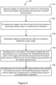
- the gaze direction data is statistically collated into a frequency distribution of gaze angles. This may include performing a statistical analysis on the gathered data over a statistically significant period of time.
- system 100 makes use of historical gaze direction data stored in memory 304 in a manner similar to that described in US Patent 8,982,046 to Edwards et al. entitled “Automatic Calibration of a Gaze Direction Algorithm from User Behavior", which is assigned to Seeing Machines Limited. The contents of US Patent 8,982,046 . This technique involves using known reference points within the scene to calibrate gaze coordinates with the scene geometry.
- the historical gaze direction data are collated statistically to form a frequency distribution of gaze angles such as in a one or two dimensional histogram having bins of gaze position or angle.
- a one dimensional gaze direction histogram is illustrated in Figure 6 .
- a similar histogram could be obtained for the orthogonal direction.
- system 100 may leverage additional data to account for these variations.
- system 100 may determine a location of a road lane in front of the vehicle by processing the images captured by forward facing camera 101. Identification of the lane markings can determine horizontal boundaries within which the driver's gaze is likely to lie. Additionally, leveraging angle of gradient of the vehicle due to road gradient by an on-board vehicle orientation sensor can be used to more accurately identify likely gaze position in the forward road scene.
- reference gaze position peak in the gaze histogram
- the largest peak in the gaze histogram is correlated with the gaze direction data by specifying that gaze position with the estimated three dimensional position of the point of regard on the road.
- This allows the correlation of a point in the frame of reference of the forward facing camera 101 with a point in the vehicle frame of reference, as captured by the driver facing camera 102.
- a camera pose of forward facing camera 101 in the vehicle frame of reference can be determined. This process can be repeated over time to more accurately calibrate the camera pose of camera 101 with the vehicle frame of reference.
- the gaze direction calculated form images of the driver's face captured from one of cameras 102-104 can be accurately mapped to the forward facing road scene captured by camera 101.
- the projection or mapping may be performed by deriving a transformation function or matrix which maps the gaze direction observed in the driver facing camera onto the forward facing road scene images captured from the forward facing camera.
- the calibration may be performed with multiple histogram peaks indicating a plurality of known reference objects or points.
- this calibration technique is dependent upon the physiology of the driver (having different head heights etc).
- face recognition can be used to register the driver and load past gaze direction data or a predetermined gaze histogram. This may optionally be augmented with the current seat height, angle and lateral positions settings for additional accuracy.
- the system and method described above provides for efficiently and accurately determining a camera pose of a forward facing camera in a multi-camera vehicle system. This allows the camera pose of a forward facing camera to be determined in a common vehicle reference frame using gaze direction data from the vehicle driver. From this, the driver's eye gaze direction captured from a driver facing camera can be projected onto images of a forward facing camera to indicate a point of regard of the driver during vehicle operation.
- controller or “processor” may refer to any device or portion of a device that processes electronic data, e.g., from registers and/or memory to transform that electronic data into other electronic data that, e.g., may be stored in registers and/or memory.
- a "computer” or a “computing machine” or a “computing platform” may include one or more processors.
- the processing system further may be a distributed processing system with processors coupled by a network. If the processing system requires a display, such a display may be included, e.g., a liquid crystal display (LCD) or a cathode ray tube (CRT) display. If manual data entry is required, the processing system also includes an input device such as one or more of an alphanumeric input unit such as a keyboard, a pointing control device such as a mouse, and so forth.
- the processing system in some configurations may include a sound output device, and a network interface device.
- the memory subsystem thus includes a computer-readable carrier medium that carries computer-readable code (e.g., software) including a set of instructions to cause performing, when executed by one or more processors, one of more of the methods described herein.
- computer-readable code e.g., software
- the software may reside in the hard disk, or may also reside, completely or at least partially, within the RAM and/or within the processor during execution thereof by the computer system.
- the memory and the processor also constitute computer-readable carrier medium carrying computer-readable code.
- a computer-readable carrier medium may form, or be included in a computer program product.
- the one or more processors operate as a standalone device or may be connected, e.g., networked to other processor(s), in a networked deployment, the one or more processors may operate in the capacity of a server or a user machine in server-user network environment, or as a peer machine in a peer-to-peer or distributed network environment.
- the one or more processors may form a personal computer (PC), a tablet PC, a set-top box (STB), a Personal Digital Assistant (PDA), a cellular telephone, a web appliance, a network router, switch or bridge, or any machine capable of executing a set of instructions (sequential or otherwise) that specify actions to be taken by that machine.
- PC personal computer
- PDA Personal Digital Assistant
- machine shall also be taken to include any collection of machines that individually or jointly execute a set (or multiple sets) of instructions to perform any one or more of the methodologies discussed herein.
- each of the methods described herein is in the form of a computer-readable carrier medium carrying a set of instructions, e.g., a computer program that is for execution on one or more processors, e.g., one or more processors that are part of web server arrangement.
- a computer-readable carrier medium carrying computer readable code including a set of instructions that when executed on one or more processors cause the processor or processors to implement a method.
- aspects of the present invention may take the form of a method, an entirely hardware embodiment, an entirely software embodiment or an embodiment combining software and hardware aspects.
- the present invention may take the form of carrier medium (e.g., a computer program product on a computer-readable storage medium) carrying computer-readable program code embodied in the medium.
- the software may further be transmitted or received over a network via a network interface device.
- the carrier medium is shown in an exemplary embodiment to be a single medium, the term “carrier medium” should be taken to include a single medium or multiple media (e.g., a centralized or distributed database, and/or associated caches and servers) that store the one or more sets of instructions.
- the term “carrier medium” shall also be taken to include any medium that is capable of storing, encoding or carrying a set of instructions for execution by one or more of the processors and that cause the one or more processors to perform any one or more of the methodologies of the present invention.
- a carrier medium may take many forms, including but not limited to, non-volatile media, volatile media, and transmission media.
- any one of the terms comprising, comprised of or which comprises is an open term that means including at least the elements/features that follow, but not excluding others.
- the term comprising, when used in the claims should not be interpreted as being limitative to the means or elements or steps listed thereafter.
- the scope of the expression a device comprising A and B should not be limited to devices consisting only of elements A and B.
- Any one of the terms including or which includes or that includes as used herein is also an open term that also means including at least the elements/features that follow the term, but not excluding others. Thus, including is synonymous with and means comprising.
- Coupled when used in the claims, should not be interpreted as being limited to direct connections only.
- the terms “coupled” and “connected,” along with their derivatives, may be used. It should be understood that these terms are not intended as synonyms for each other.
- the scope of the expression a device A coupled to a device B should not be limited to devices or systems wherein an output of device A is directly connected to an input of device B. It means that there exists a path between an output of A and an input of B which may be a path including other devices or means.
- Coupled may mean that two or more elements are either in direct physical, electrical or optical contact, or that two or more elements are not in direct contact with each other but yet still co-operate or interact with each other.
Landscapes
- Engineering & Computer Science (AREA)
- Physics & Mathematics (AREA)
- General Physics & Mathematics (AREA)
- Theoretical Computer Science (AREA)
- Computer Vision & Pattern Recognition (AREA)
- Multimedia (AREA)
- Health & Medical Sciences (AREA)
- General Health & Medical Sciences (AREA)
- Human Computer Interaction (AREA)
- Geometry (AREA)
- Signal Processing (AREA)
- Ophthalmology & Optometry (AREA)
- Oral & Maxillofacial Surgery (AREA)
- Image Analysis (AREA)
- Traffic Control Systems (AREA)
- Length Measuring Devices By Optical Means (AREA)
- Image Processing (AREA)
- Studio Devices (AREA)
Claims (14)
- Procédé de détermination d'une pose de caméra d'une caméra (101) face-avant dans une scène de véhicule, le procédé incluant les étapes consistant à :a) capturer (501) des images d'un visage d'un conducteur de véhicule à partir d'une caméra (102) face-conducteur dans la trame de référence de caméra (102) face-conducteur et des images de la scène de route à l'avant à partir d'une caméra (101) face-avant dans la trame de référence de caméra (101) face-avant pendant un fonctionnement normal du véhicule (106) quand le conducteur est assis dans le siège de conducteur et actionne le véhicule ;b) traiter (502) les images du visage du conducteur à partir de la caméra (102) face-conducteur pour dériver des données de direction de regard dans une trame de référence de véhicule ;c) collecter (503) statistiquement les données de direction de regard dans une distribution de fréquence d'angles de regard ;d) identifier (504) un ou plusieurs pics dans la distribution de fréquence et associer lesdits un ou plusieurs pics à un ou plusieurs points de référence correspondants dans les images de la scène de route à l'avant à partir de la caméra (101) face-avant pour déterminer un ou plusieurs points de regard de référence dans la trame de référence de véhicule ; ete) corréler (505) lesdits un ou plusieurs points de regard de référence avec une position des points de référence dans la trame de référence de caméra face-avant pour faire correspondre les données de direction de regard aux images de la scène de route tournée vers l'avant afin de déterminer une pose de caméra de la caméra (101) face-avant dans la trame de référence de véhicule de sorte que la direction de regard de l'oeil du conducteur capturée par la caméra (102) face-conducteur peut être projetée sur des images de la caméra (101) face-avant pour indiquer un point de regard du conducteur pendant un fonctionnement du véhicule.
- Procédé selon la revendication 1, dans lequel lesdits un ou plusieurs points de référence incluent une position de la route à l'avant du véhicule (106).
- Procédé selon la revendication 2, dans lequel l'étape d) inclut de déterminer un emplacement d'une voie de route à l'avant du véhicule (106) en traitant les images capturées par la caméra (101) face-avant.
- Procédé selon la revendication 2 or 3, dans lequel l'étape d) inclut de déterminer un angle d'un gradient du véhicule (106).
- Procédé selon l'une quelconque des revendications 2 à 4, dans lequel l'étape d) inclut d'identifier la position de la tête du conducteur à l'intérieur de l'habitacle de véhicule.
- Procédé selon la revendication 5, dans lequel la position de la tête du conducteur est identifiée en effectuant une reconnaissance faciale sur le conducteur et en chargeant des données physiologiques.
- Procédé selon la revendication 5 ou 6, dans lequel il est déterminé une hauteur, un angle et/ou une position latérale de siège du siège de conducteur.
- Procédé selon l'une quelconque des revendications précédentes, dans lequel l'étape b) inclut de :i. déterminer la pose de caméra de la caméra (102) face-conducteur dans une trame de référence de véhicule ; etii. transformer les données de direction de regard dans la trame de référence de véhicule.
- Procédé selon la revendication 8, dans lequel l'étape b)i. inclut de déterminer l'orientation de la caméra (102) face-conducteur dans le système de coordonnées de véhicule en utilisant un détecteur d'orientation.
- Procédé selon la revendication 8, dans lequel l'étape b)i. inclut deA. capturer une ou plusieurs images de la scène de véhicule à partir de la caméra (102) face-conducteur ; etB. comparer lesdites une ou plusieurs images de la scène de véhicule à des informations de référence concernant la scène véhicule.
- Procédé selon la revendication 1, dans lequel lesdits un ou plusieurs points de regard de référence sont déterminés par un processus d'apprentissage automatique alimenté par des données de direction de regard, des données de positions de voie, et des données de gradient de véhicule pour apprendre des motifs de comportement de regard.
- Système de surveillance de véhicule incluant :une ou plusieurs caméras (102) face-conducteur positionnées pour capturer des images d'un visage d'un conducteur de véhicule dans la trame de référence de caméra (102) face-conducteur pendant un fonctionnement normal du véhicule (106) quand le conducteur est assis dans le siège de conducteur et actionne le véhicule ;une caméra (101) face-avant positionnée pour capturer des images d'une scène de route tournée vers l'avant du véhicule dans la trame de référence de caméra (101) face-avant pendant un fonctionnement normal du véhicule (106) ;un processeur d'ordinateur configuré pour :traiter les images du visage du conducteur à partir de la caméra (102) face-conducteur pour dériver des données de direction de regard dans une trame de référence de véhicule ;collecter statistiquement les données de direction de regard jusque dans une distribution de fréquence d'angles de regard ;identifier un ou plusieurs pics dans la distribution de fréquence et associer lesdits un ou plusieurs pics à un ou plusieurs points de référence correspondants dans les images de la scène de route à l'avant à partir de la caméra (101) face-avant pour déterminer un ou plusieurs points de regard de référence dans la trame de référence de véhicule ; etcorréler lesdits un ou plusieurs points de regard de référence avec une position des points de référence dans la trame de référence de caméra face-avant pour faire correspondre les données de direction de regard aux images de la scène de route tournée vers l'avant afin de déterminer une pose de caméra de la caméra (101) face-avant dans la trame de référence de véhicule de sorte que la direction de regard de l'œil du conducteur capturée par la caméra (102) face-conducteur peut être projetée sur des images de la caméra (101) face-avant pour indiquer un point de regard du conducteur pendant un fonctionnement du véhicule.
- Programme d'ordinateur comprenant des instructions destinées à amener le système selon la revendication 12 à exécuter les étapes du procédé selon la revendication 1.
- Support lisible par ordinateur ayant, stocké sur celui-ci, le programme d'ordinateur selon la revendication 13.
Applications Claiming Priority (2)
| Application Number | Priority Date | Filing Date | Title |
|---|---|---|---|
| AU2016902547A AU2016902547A0 (en) | 2016-06-29 | Method for automatic calibration of cameras in a multi-camera system and forward gaze projection | |
| PCT/AU2017/050668 WO2018000038A1 (fr) | 2016-06-29 | 2017-06-29 | Système et procédé d'identification d'une pose de caméra d'une caméra orientée vers l'avant dans un véhicule |
Publications (3)
| Publication Number | Publication Date |
|---|---|
| EP3479356A1 EP3479356A1 (fr) | 2019-05-08 |
| EP3479356A4 EP3479356A4 (fr) | 2020-03-25 |
| EP3479356B1 true EP3479356B1 (fr) | 2025-04-16 |
Family
ID=60784971
Family Applications (3)
| Application Number | Title | Priority Date | Filing Date |
|---|---|---|---|
| EP17818744.9A Active EP3479356B1 (fr) | 2016-06-29 | 2017-06-29 | Système et procédé d'identification d'une pose de caméra d'une caméra orientée vers l'avant dans un véhicule |
| EP17818743.1A Active EP3479353B1 (fr) | 2016-06-29 | 2017-06-29 | Systèmes et procédés d'identification de la pose de caméras dans une scène |
| EP24170475.8A Pending EP4394732A3 (fr) | 2016-06-29 | 2017-06-29 | Systèmes et procédés d'identification de la pose de caméras dans une scène |
Family Applications After (2)
| Application Number | Title | Priority Date | Filing Date |
|---|---|---|---|
| EP17818743.1A Active EP3479353B1 (fr) | 2016-06-29 | 2017-06-29 | Systèmes et procédés d'identification de la pose de caméras dans une scène |
| EP24170475.8A Pending EP4394732A3 (fr) | 2016-06-29 | 2017-06-29 | Systèmes et procédés d'identification de la pose de caméras dans une scène |
Country Status (5)
| Country | Link |
|---|---|
| US (2) | US10726576B2 (fr) |
| EP (3) | EP3479356B1 (fr) |
| JP (1) | JP7161410B2 (fr) |
| CN (1) | CN109690623B (fr) |
| WO (2) | WO2018000038A1 (fr) |
Families Citing this family (76)
| Publication number | Priority date | Publication date | Assignee | Title |
|---|---|---|---|---|
| JP6333871B2 (ja) * | 2016-02-25 | 2018-05-30 | ファナック株式会社 | 入力画像から検出した対象物を表示する画像処理装置 |
| CA3047161A1 (fr) | 2017-03-01 | 2018-09-07 | Synergie Medicale Brg Inc. | Systeme de remplissage automatique d'organiseurs de medicaments |
| US10929987B2 (en) | 2017-08-16 | 2021-02-23 | Nvidia Corporation | Learning rigidity of dynamic scenes for three-dimensional scene flow estimation |
| US10948299B1 (en) * | 2017-09-28 | 2021-03-16 | Apple Inc. | Relative inertial measurement system with visual correction |
| DE102018203405A1 (de) * | 2018-03-07 | 2019-09-12 | Zf Friedrichshafen Ag | Visuelles Surround-View-System zur Überwachung des Fahrzeuginneren |
| US11941847B2 (en) * | 2018-03-19 | 2024-03-26 | Jaguar Land Rover Limited | Controller for a vehicle |
| US10977827B2 (en) * | 2018-03-27 | 2021-04-13 | J. William Mauchly | Multiview estimation of 6D pose |
| CN118840433A (zh) * | 2018-05-25 | 2024-10-25 | 派克赛斯有限责任公司 | 用于多相机放置的系统和方法 |
| US10849543B2 (en) | 2018-06-08 | 2020-12-01 | Ford Global Technologies, Llc | Focus-based tagging of sensor data |
| US10991121B2 (en) * | 2018-11-27 | 2021-04-27 | GM Global Technology Operations LLC | Movement tracking of operator-facing cameras |
| US11805390B2 (en) | 2018-12-05 | 2023-10-31 | Here Global B.V. | Method, apparatus, and computer program product for determining sensor orientation |
| US11383656B2 (en) | 2018-12-11 | 2022-07-12 | Sony Group Corporation | Image processing apparatus, image processing method, and image processing system |
| US11677930B2 (en) | 2018-12-20 | 2023-06-13 | Here Global B.V. | Method, apparatus, and system for aligning a vehicle-mounted device |
| US10657396B1 (en) * | 2019-01-30 | 2020-05-19 | StradVision, Inc. | Method and device for estimating passenger statuses in 2 dimension image shot by using 2 dimension camera with fisheye lens |
| US10728461B1 (en) * | 2019-01-31 | 2020-07-28 | StradVision, Inc. | Method for correcting misalignment of camera by selectively using information generated by itself and information generated by other entities and device using the same |
| DE102019201633A1 (de) | 2019-02-08 | 2020-08-13 | Zf Friedrichshafen Ag | Kalibrierung eines Sensors für ein Fahrzeug basierend auf objektseitigen und bildseitigen Identifikationsindizes eines Referenzobjektes |
| US12399015B2 (en) * | 2019-04-12 | 2025-08-26 | Nvidia Corporation | Neural network training using ground truth data augmented with map information for autonomous machine applications |
| US11639234B2 (en) | 2019-04-24 | 2023-05-02 | The Boeing Company | Method, system and apparatus for aligning a removable sensor on a vehicle |
| CA3076342A1 (fr) * | 2019-04-24 | 2020-10-24 | The Boeing Company | Alignement des capteurs sur les vehicules au moyen des sorties des capteurs |
| US12123983B2 (en) | 2019-04-24 | 2024-10-22 | The Boeing Company | Aligning sensors on vehicles using sensor output |
| US11003956B2 (en) * | 2019-05-16 | 2021-05-11 | Naver Corporation | System and method for training a neural network for visual localization based upon learning objects-of-interest dense match regression |
| US11144754B2 (en) * | 2019-08-19 | 2021-10-12 | Nvidia Corporation | Gaze detection using one or more neural networks |
| WO2021121836A1 (fr) * | 2019-12-19 | 2021-06-24 | Sony Semiconductor Solutions Corporation | Système de caméra pour un dispositif mobile, procédé de localisation d'une caméra et procédé de localisation d'une pluralité de caméras |
| US11928789B2 (en) | 2019-12-19 | 2024-03-12 | Zf Friedrichshafen Ag | Vehicle vision system |
| JP7384043B2 (ja) * | 2020-01-10 | 2023-11-21 | 株式会社デンソー | 検出器の姿勢・位置検出システムおよび検出器の姿勢・位置検出方法 |
| EP3885237B1 (fr) * | 2020-03-24 | 2025-06-11 | Aptiv Technologies AG | Véhicule, système et procédé pour déterminer une position d'une caméra montée sur un volant dans un véhicule |
| US11568655B2 (en) | 2020-03-26 | 2023-01-31 | Intel Corporation | Methods and devices for triggering vehicular actions based on passenger actions |
| US11582409B2 (en) * | 2020-06-29 | 2023-02-14 | Snap Inc. | Visual-inertial tracking using rolling shutter cameras |
| KR20220002800A (ko) * | 2020-06-30 | 2022-01-07 | 현대모비스 주식회사 | 운전자 부주의 경고 장치 및 방법 |
| US11282233B1 (en) * | 2020-09-08 | 2022-03-22 | Weta Digital Limited | Motion capture calibration |
| US11232595B1 (en) | 2020-09-08 | 2022-01-25 | Weta Digital Limited | Three-dimensional assembly for motion capture calibration |
| WO2022094787A1 (fr) * | 2020-11-04 | 2022-05-12 | 深圳市大疆创新科技有限公司 | Système de traitement de données de conducteur et procédé d'acquisition de données de conducteur |
| CN116829902A (zh) | 2020-12-14 | 2023-09-29 | 夏日机器人公司 | 基于感测表面和感测表面运动来感知物体 |
| CN116761745A (zh) * | 2020-12-23 | 2023-09-15 | 石通瑞吉电子公司 | 相机视镜系统显示器相机校准 |
| WO2022172391A1 (fr) * | 2021-02-12 | 2022-08-18 | 三菱電機株式会社 | Dispositif de détermination d'état d'occupant et procédé de détermination d'état d'occupant |
| US11977150B2 (en) * | 2021-03-05 | 2024-05-07 | Black Sesame Technologies Inc. | Vehicle localization precision enhancement via multi-sensor fusion |
| US20240378904A1 (en) * | 2021-05-05 | 2024-11-14 | Seeing Machines Limited | Systems and methods for detection of mobile device use by a vehicle driver |
| US20220363194A1 (en) * | 2021-05-11 | 2022-11-17 | Magna Electronics Inc. | Vehicular display system with a-pillar display |
| US11715257B2 (en) | 2021-05-14 | 2023-08-01 | Zoox, Inc. | Simulation view generation based on simulated sensor operations |
| US11544896B2 (en) | 2021-05-14 | 2023-01-03 | Zoox, Inc. | Spatial and temporal upsampling techniques for simulated sensor data |
| US11741661B2 (en) | 2021-05-14 | 2023-08-29 | Zoox, Inc. | Sensor simulation with unified multi-sensor views |
| WO2023278868A1 (fr) * | 2021-07-01 | 2023-01-05 | Summer Robotics, Inc. | Étalonnage de décalages de position de capteur sur la base de vecteurs de rotation et de translation pour trajectoires concordantes |
| CN113506346B (zh) * | 2021-07-06 | 2023-08-29 | 广东工业大学 | 一种应用于弱纹理大旋转场景下的相机的位姿求解方法 |
| US12148185B2 (en) | 2021-07-15 | 2024-11-19 | Summer Robotics, Inc. | Automatic parameter adjustment for scanning event cameras |
| US11704835B2 (en) | 2021-07-29 | 2023-07-18 | Summer Robotics, Inc. | Dynamic calibration of 3D acquisition systems |
| GB2609619A (en) * | 2021-08-05 | 2023-02-15 | Continental Automotive Gmbh | A method for determining deviation in alignment of a camera in a vehicle |
| AU2022332110A1 (en) | 2021-08-23 | 2024-02-15 | Gentex Corporation | Rearview assembly adjustment system |
| US11808857B2 (en) | 2021-08-27 | 2023-11-07 | Summer Robotics, Inc. | Multi-sensor superresolution scanning and capture system |
| WO2023096873A1 (fr) | 2021-11-28 | 2023-06-01 | Summer Robotics, Inc. | Association de pistes concurrentes à travers de multiples vues |
| JP7134384B1 (ja) * | 2022-01-11 | 2022-09-09 | 三菱電機株式会社 | ずれ量検出装置、ずれ量検出方法及びドライバモニタリングシステム |
| JP7582214B2 (ja) * | 2022-01-11 | 2024-11-13 | トヨタ自動車株式会社 | 路面標示検出装置及びこれを備える報知システム、並びに路面標示検出方法 |
| CN114049404B (zh) * | 2022-01-12 | 2022-04-05 | 深圳佑驾创新科技有限公司 | 一种车内相机外参标定方法及装置 |
| US12479364B2 (en) | 2022-02-25 | 2025-11-25 | Gentex Corporation | Vehicle rearview display system with orientation sensing |
| WO2023164064A1 (fr) | 2022-02-27 | 2023-08-31 | Summer Robotics, Inc. | Association de pistes concurrentes à l'aide de croisements de graphes |
| US12591998B2 (en) * | 2022-03-08 | 2026-03-31 | Mitsubishi Electric Corporation | Occupant monitoring device, occupant monitoring method, and medium |
| WO2023177692A1 (fr) | 2022-03-14 | 2023-09-21 | Summer Robotics, Inc. | Scène de studio pour capture vidéo 3d immersive |
| KR20230158335A (ko) * | 2022-05-11 | 2023-11-20 | 현대자동차주식회사 | 차량 및 그 제어 방법 |
| US12401905B2 (en) | 2022-07-14 | 2025-08-26 | Summer Robotics, Inc. | Foveated robotic vision system |
| JP2024029755A (ja) * | 2022-08-22 | 2024-03-06 | シーイング マシーンズ リミテッド | 自動防眩ミラー |
| KR20240030098A (ko) * | 2022-08-29 | 2024-03-07 | 현대자동차주식회사 | 차량 및 차량의 제어 방법 |
| US11974055B1 (en) | 2022-10-17 | 2024-04-30 | Summer Robotics, Inc. | Perceiving scene features using event sensors and image sensors |
| EP4365842A1 (fr) * | 2022-11-02 | 2024-05-08 | Smart Eye AB | Étalonnage d'un système de coordonnées de caméra |
| US12276730B2 (en) | 2022-11-08 | 2025-04-15 | Summer Robotics, Inc. | Virtual fences in air, water, and space |
| US20240249435A1 (en) * | 2023-01-20 | 2024-07-25 | Tusimple, Inc. | System and method for using dynamic objects to estimate camera pose |
| US12340594B2 (en) * | 2023-02-01 | 2025-06-24 | Verizon Patent And Licensing Inc. | Systems and methods for determining road object importance based on forward facing and driver facing video data |
| US12561839B2 (en) * | 2023-02-16 | 2026-02-24 | Ford Global Technologies, Llc | Systems and methods for calibrating image sensors of a vehicle |
| JP2024171980A (ja) * | 2023-05-31 | 2024-12-12 | 株式会社テクノクラフト | 自走式カートの監視システム及びプログラム |
| US12325414B2 (en) * | 2023-06-02 | 2025-06-10 | GM Global Technology Operations LLC | Methods and systems for tracking of attached objects |
| US20240430574A1 (en) * | 2023-06-20 | 2024-12-26 | Rivian Ip Holdings, Llc | Vehicle camera system |
| DE102023122452B3 (de) | 2023-08-22 | 2025-01-23 | Cariad Se | Verfahren zur Ausgabe eines Handlungssignals an einen Insassen in einem Kraftfahrzeug |
| DE102024100306B3 (de) * | 2024-01-08 | 2025-03-20 | Bayerische Motoren Werke Aktiengesellschaft | Vorrichtung und Verfahren zum Kalibrieren einer im Innenraum eines Fahrzeugs angeordneten Innenraumkamera |
| DE102024202949A1 (de) * | 2024-03-28 | 2025-10-02 | Siemens Mobility GmbH | Automatische Überprüfung und Re-Justierung einer statischen Bildaufnahmeeinheit |
| TWI879689B (zh) * | 2024-04-24 | 2025-04-01 | 光寶科技股份有限公司 | 套件裝置、標定系統及其操作方法 |
| US20250342609A1 (en) * | 2024-05-06 | 2025-11-06 | DISTANCE TECHNOLOGIES Oy | On-the-fly recalibration of tracking camera |
| US12416804B1 (en) | 2024-05-08 | 2025-09-16 | Summer Robotics, Inc. | Kaleidoscopic laser beam projection system |
| US20250371732A1 (en) * | 2024-05-30 | 2025-12-04 | Nvidia Corporation | Neural network-based identification of poses of cameras |
Family Cites Families (62)
| Publication number | Priority date | Publication date | Assignee | Title |
|---|---|---|---|---|
| US8604932B2 (en) * | 1992-05-05 | 2013-12-10 | American Vehicular Sciences, LLC | Driver fatigue monitoring system and method |
| JPH10326138A (ja) * | 1997-05-26 | 1998-12-08 | Toshiba Corp | キー入力装置 |
| JP3833786B2 (ja) * | 1997-08-04 | 2006-10-18 | 富士重工業株式会社 | 移動体の3次元自己位置認識装置 |
| US6535114B1 (en) * | 2000-03-22 | 2003-03-18 | Toyota Jidosha Kabushiki Kaisha | Method and apparatus for environment recognition |
| US6354894B1 (en) * | 2000-04-13 | 2002-03-12 | Robert B. Evans | Spear-blade swim fin |
| AUPQ896000A0 (en) | 2000-07-24 | 2000-08-17 | Seeing Machines Pty Ltd | Facial image processing system |
| JP3620443B2 (ja) | 2000-12-05 | 2005-02-16 | 日産自動車株式会社 | 自動車用表示装置 |
| JP3790680B2 (ja) | 2001-05-25 | 2006-06-28 | 株式会社東芝 | 画像処理システム及びこれを用いた運転支援システム |
| DE10159658A1 (de) * | 2001-12-05 | 2003-06-26 | Daimler Chrysler Ag | System zur automatischen Folgeführung eines Kraftfahrzeugs |
| DE10218010A1 (de) * | 2002-04-23 | 2003-11-06 | Bosch Gmbh Robert | Verfahren und Vorrichtung zur Querführungsunterstützung bei Kraftfahrzeugen |
| CN101317763B (zh) | 2002-10-15 | 2013-04-03 | 沃尔沃技术公司 | 解释对象的头部和眼睛活动的方法和装置 |
| US6859144B2 (en) | 2003-02-05 | 2005-02-22 | Delphi Technologies, Inc. | Vehicle situation alert system with eye gaze controlled alert signal generation |
| DE10318500A1 (de) * | 2003-04-24 | 2004-11-25 | Robert Bosch Gmbh | Vorrichtung und Verfahren zur Kalibrierung eines Bildsensors |
| WO2004106856A1 (fr) | 2003-05-29 | 2004-12-09 | Olympus Corporation | Dispositif et procede de support de camera stereo, dispositif et procede de detection d'etalonnage, et systeme de camera stereo |
| JP2004354236A (ja) * | 2003-05-29 | 2004-12-16 | Olympus Corp | ステレオカメラ支持装置およびステレオカメラ支持方法ならびにステレオカメラシステム |
| JP4456855B2 (ja) * | 2003-12-08 | 2010-04-28 | 富士重工業株式会社 | 車両の走行制御装置 |
| JP3915776B2 (ja) * | 2003-12-09 | 2007-05-16 | 日産自動車株式会社 | 先行車両検出装置、自車両制御装置及び先行車両検出方法 |
| JP4765301B2 (ja) | 2004-11-25 | 2011-09-07 | 沖電気工業株式会社 | 半導体装置の製造方法 |
| JP4767578B2 (ja) * | 2005-02-14 | 2011-09-07 | 株式会社岩根研究所 | 高精度cv演算装置と、この高精度cv演算装置を備えたcv方式三次元地図生成装置及びcv方式航法装置 |
| JP4926437B2 (ja) * | 2005-09-28 | 2012-05-09 | 富士重工業株式会社 | 車両の運転支援装置 |
| JP4810953B2 (ja) * | 2005-10-07 | 2011-11-09 | 日産自動車株式会社 | 車両用死角映像表示装置 |
| US20090295921A1 (en) * | 2005-10-12 | 2009-12-03 | Pioneer Corporation | Vehicle-mounted photographing device and method of measuring photographable range of vehicle-mounted camera |
| JP5036814B2 (ja) | 2006-06-11 | 2012-09-26 | ボルボ テクノロジー コーポレイション | 視覚的関心場所の決定および分析のための方法および装置 |
| US8059887B2 (en) * | 2006-09-25 | 2011-11-15 | Sri International | System and method for providing mobile range sensing |
| KR20090052413A (ko) | 2007-11-21 | 2009-05-26 | 주식회사 현대오토넷 | 운전자 시선 대응 전방 화면 디스플레이 장치 및 방법 |
| JP2009136551A (ja) | 2007-12-07 | 2009-06-25 | Denso Corp | 車両用顔特徴量検出装置及び顔特徴量検出方法 |
| US8392064B2 (en) * | 2008-05-27 | 2013-03-05 | The Board Of Trustees Of The Leland Stanford Junior University | Systems, methods and devices for adaptive steering control of automotive vehicles |
| US8478493B2 (en) * | 2008-09-11 | 2013-07-02 | Deere & Company | High integrity perception program |
| WO2010071928A1 (fr) | 2008-12-22 | 2010-07-01 | Seeing Machines Limited | Étalonnage automatique d'un algorithme de direction du regard à partir du comportement de l'utilisateur |
| DE102008063328A1 (de) * | 2008-12-30 | 2010-07-01 | Hella Kgaa Hueck & Co. | Verfahren und Vorrichtung zum Ermitteln einer Änderung des Nickwinkels einer Kamera eines Fahrzeugs |
| US8698875B2 (en) * | 2009-02-20 | 2014-04-15 | Google Inc. | Estimation of panoramic camera orientation relative to a vehicle coordinate frame |
| JP2010256878A (ja) * | 2009-03-30 | 2010-11-11 | Equos Research Co Ltd | 情報表示装置 |
| WO2011112633A1 (fr) * | 2010-03-09 | 2011-09-15 | Flir Systems, Inc. | Imageur avec réseaux de capteurs multiples |
| WO2011141984A1 (fr) * | 2010-05-10 | 2011-11-17 | トヨタ自動車株式会社 | Appareil de calcul de risque |
| WO2011155878A1 (fr) | 2010-06-10 | 2011-12-15 | Volvo Lastavagnar Ab | Système d'affichage basé sur un véhicule et son procédé d'utilisation |
| FR2962581B1 (fr) | 2010-07-06 | 2013-07-05 | Imajing | Methode de calibration de l'orientation d'une camera video embarquee |
| US8957948B2 (en) | 2010-08-24 | 2015-02-17 | Siemens Corporation | Geometric calibration of head-worn multi-camera eye tracking system |
| JP5476264B2 (ja) * | 2010-09-22 | 2014-04-23 | 日本放送協会 | カメラトラッキング装置およびそのプログラム |
| JP5892309B2 (ja) | 2011-10-27 | 2016-03-23 | マツダ株式会社 | 車両用視線誘導装置 |
| US8941561B1 (en) | 2012-01-06 | 2015-01-27 | Google Inc. | Image capture |
| US8915738B2 (en) | 2012-01-24 | 2014-12-23 | Toyota Motor Engineering & Manufacturing North America, Inc. | Driver quality assessment for driver education |
| US8880272B1 (en) * | 2012-03-16 | 2014-11-04 | Google Inc. | Approach for estimating the geometry of roads and lanes by using vehicle trajectories |
| US8702250B2 (en) * | 2012-04-02 | 2014-04-22 | GM Global Technology Operations LLC | System and method for adjusting vehicle mirrors automatically based on driver head position |
| US9423870B2 (en) | 2012-05-08 | 2016-08-23 | Google Inc. | Input determination method |
| US9150238B2 (en) * | 2012-06-04 | 2015-10-06 | GM Global Technology Operations LLC | System and method for automatically adjusting a steering tilt position |
| JP5931646B2 (ja) * | 2012-08-20 | 2016-06-08 | Kddi株式会社 | 画像処理装置 |
| US9036865B2 (en) * | 2012-09-12 | 2015-05-19 | International Business Machines Corporation | Location determination for an object using visual data |
| US9405982B2 (en) * | 2013-01-18 | 2016-08-02 | GM Global Technology Operations LLC | Driver gaze detection system |
| KR102118438B1 (ko) | 2013-01-28 | 2020-06-04 | 한국전자통신연구원 | 차량용 헤드업 디스플레이 장치 및 그 방법 |
| US8885925B2 (en) * | 2013-03-12 | 2014-11-11 | Harris Corporation | Method for 3D object identification and pose detection using phase congruency and fractal analysis |
| WO2014152254A2 (fr) | 2013-03-15 | 2014-09-25 | Carnegie Robotics Llc | Procédés, systèmes, et appareil de vision stéréoscopique multi-sensorielle pour la robotique |
| US9280202B2 (en) | 2013-05-10 | 2016-03-08 | Magna Electronics Inc. | Vehicle vision system |
| US9483703B2 (en) * | 2013-05-14 | 2016-11-01 | University Of Southern California | Online coupled camera pose estimation and dense reconstruction from video |
| US9563951B2 (en) * | 2013-05-21 | 2017-02-07 | Magna Electronics Inc. | Vehicle vision system with targetless camera calibration |
| US9881221B2 (en) | 2013-10-24 | 2018-01-30 | Conduent Business Services, Llc | Method and system for estimating gaze direction of vehicle drivers |
| US9354073B2 (en) | 2013-12-09 | 2016-05-31 | Harman International Industries, Inc. | Eye gaze enabled navigation system |
| JP6264037B2 (ja) * | 2013-12-27 | 2018-01-24 | トヨタ自動車株式会社 | 車両用情報表示装置及び車両用情報表示方法 |
| CN103770733B (zh) * | 2014-01-15 | 2017-01-11 | 中国人民解放军国防科学技术大学 | 一种驾驶员安全驾驶状态检测方法及装置 |
| US9817474B2 (en) | 2014-01-24 | 2017-11-14 | Tobii Ab | Gaze driven interaction for a vehicle |
| GB2528446B (en) * | 2014-07-21 | 2021-08-04 | Tobii Tech Ab | Method and apparatus for detecting and following an eye and/or the gaze direction thereof |
| US9437055B2 (en) * | 2014-08-13 | 2016-09-06 | Bendix Commercial Vehicle Systems Llc | Cabin and trailer body movement determination with camera at the back of the cabin |
| WO2016029939A1 (fr) * | 2014-08-27 | 2016-03-03 | Metaio Gmbh | Procédé et système pour déterminer au moins une caractéristique d'image dans au moins une image |
-
2017
- 2017-06-29 WO PCT/AU2017/050668 patent/WO2018000038A1/fr not_active Ceased
- 2017-06-29 CN CN201780041110.4A patent/CN109690623B/zh active Active
- 2017-06-29 EP EP17818744.9A patent/EP3479356B1/fr active Active
- 2017-06-29 US US16/312,458 patent/US10726576B2/en active Active
- 2017-06-29 EP EP17818743.1A patent/EP3479353B1/fr active Active
- 2017-06-29 EP EP24170475.8A patent/EP4394732A3/fr active Pending
- 2017-06-29 JP JP2018563670A patent/JP7161410B2/ja active Active
- 2017-06-29 WO PCT/AU2017/050667 patent/WO2018000037A1/fr not_active Ceased
- 2017-06-29 US US16/311,471 patent/US10909721B2/en active Active
Also Published As
| Publication number | Publication date |
|---|---|
| EP4394732A3 (fr) | 2024-10-09 |
| US20190266751A1 (en) | 2019-08-29 |
| CN109690623B (zh) | 2023-11-07 |
| US10909721B2 (en) | 2021-02-02 |
| US10726576B2 (en) | 2020-07-28 |
| US20190206084A1 (en) | 2019-07-04 |
| JP2019526101A (ja) | 2019-09-12 |
| WO2018000038A1 (fr) | 2018-01-04 |
| EP3479356A1 (fr) | 2019-05-08 |
| EP3479353A4 (fr) | 2020-03-18 |
| CN109690623A (zh) | 2019-04-26 |
| WO2018000037A1 (fr) | 2018-01-04 |
| EP4394732A2 (fr) | 2024-07-03 |
| EP3479356A4 (fr) | 2020-03-25 |
| JP7161410B2 (ja) | 2022-10-26 |
| EP3479353B1 (fr) | 2024-05-01 |
| EP3479353A1 (fr) | 2019-05-08 |
Similar Documents
| Publication | Publication Date | Title |
|---|---|---|
| EP3479356B1 (fr) | Système et procédé d'identification d'une pose de caméra d'une caméra orientée vers l'avant dans un véhicule | |
| EP3479352B1 (fr) | Enregistrement de caméra dans un système multicaméras | |
| CN103502876B (zh) | 用于校正车辆的投影装置的方法和设备 | |
| EP4024340B1 (fr) | Système d'affinage d'une estimation de la pose d'un objet cible à six degrés de liberté | |
| EP3942522B1 (fr) | Système et procédé de traitement d'image | |
| JPWO2017159382A1 (ja) | 信号処理装置および信号処理方法 | |
| US20140085409A1 (en) | Wide fov camera image calibration and de-warping | |
| US9679406B2 (en) | Systems and methods for providing a visualization of satellite sightline obstructions | |
| JP4803449B2 (ja) | 車載カメラの校正装置、校正方法、並びにこの校正方法を用いた車両の生産方法 | |
| CN109703465B (zh) | 车载图像传感器的控制方法和装置 | |
| EP3326145B1 (fr) | Transformation de tableau | |
| WO2018222122A1 (fr) | Procédés de correction de perspective, produits programmes d'ordinateur et systèmes | |
| US9892519B2 (en) | Method for detecting an object in an environmental region of a motor vehicle, driver assistance system and motor vehicle | |
| US9849835B2 (en) | Operating a head-up display of a vehicle and image determining system for the head-up display | |
| EP3326146B1 (fr) | Observations rapides de circulation transversale arrière | |
| EP3486871B1 (fr) | Système de vision et procédé pour entraînement autonome et/ou d'aide à la conduite dans un véhicule à moteur | |
| CN109345591A (zh) | 一种车辆自身姿态检测方法和装置 | |
| WO2021056283A1 (fr) | Systèmes et procédés de réglage d'une position de véhicule | |
| CN118004035B (zh) | 一种基于车载投影仪的辅助驾驶方法、装置及电子设备 | |
| CN117441190A (zh) | 一种部位定位方法及装置 | |
| CN118505512A (zh) | 图像超分辨率增强方法、装置、设备及存储介质 | |
| CN120236023A (zh) | 用于创建三维点云地图的方法、装置、设备、车辆和介质 | |
| KR20160144645A (ko) | 어라운드 뷰 제공장치 및 이를 구비한 차량 |
Legal Events
| Date | Code | Title | Description |
|---|---|---|---|
| STAA | Information on the status of an ep patent application or granted ep patent |
Free format text: STATUS: THE INTERNATIONAL PUBLICATION HAS BEEN MADE |
|
| PUAI | Public reference made under article 153(3) epc to a published international application that has entered the european phase |
Free format text: ORIGINAL CODE: 0009012 |
|
| STAA | Information on the status of an ep patent application or granted ep patent |
Free format text: STATUS: REQUEST FOR EXAMINATION WAS MADE |
|
| 17P | Request for examination filed |
Effective date: 20190129 |
|
| AK | Designated contracting states |
Kind code of ref document: A1 Designated state(s): AL AT BE BG CH CY CZ DE DK EE ES FI FR GB GR HR HU IE IS IT LI LT LU LV MC MK MT NL NO PL PT RO RS SE SI SK SM TR |
|
| AX | Request for extension of the european patent |
Extension state: BA ME |
|
| DAV | Request for validation of the european patent (deleted) | ||
| DAX | Request for extension of the european patent (deleted) | ||
| REG | Reference to a national code |
Ref country code: DE Ref legal event code: R079 Free format text: PREVIOUS MAIN CLASS: G06T0007800000 Ipc: G06K0009000000 |
|
| A4 | Supplementary search report drawn up and despatched |
Effective date: 20200221 |
|
| RIC1 | Information provided on ipc code assigned before grant |
Ipc: G06T 7/73 20170101ALI20200217BHEP Ipc: G06T 7/80 20170101ALI20200217BHEP Ipc: G06K 9/00 20060101AFI20200217BHEP Ipc: G06K 9/62 20060101ALI20200217BHEP |
|
| STAA | Information on the status of an ep patent application or granted ep patent |
Free format text: STATUS: EXAMINATION IS IN PROGRESS |
|
| 17Q | First examination report despatched |
Effective date: 20211119 |
|
| P01 | Opt-out of the competence of the unified patent court (upc) registered |
Effective date: 20230420 |
|
| REG | Reference to a national code |
Ref country code: DE Free format text: PREVIOUS MAIN CLASS: G06K0009000000 Ref country code: DE Ref legal event code: R079 Ref document number: 602017088966 Country of ref document: DE Free format text: PREVIOUS MAIN CLASS: G06K0009000000 Ipc: G06V0020590000 |
|
| RIC1 | Information provided on ipc code assigned before grant |
Ipc: G06T 7/80 20170101ALI20241017BHEP Ipc: G06T 7/73 20170101ALI20241017BHEP Ipc: G06V 20/59 20220101AFI20241017BHEP |
|
| GRAP | Despatch of communication of intention to grant a patent |
Free format text: ORIGINAL CODE: EPIDOSNIGR1 |
|
| STAA | Information on the status of an ep patent application or granted ep patent |
Free format text: STATUS: GRANT OF PATENT IS INTENDED |
|
| INTG | Intention to grant announced |
Effective date: 20241202 |
|
| GRAS | Grant fee paid |
Free format text: ORIGINAL CODE: EPIDOSNIGR3 |
|
| GRAA | (expected) grant |
Free format text: ORIGINAL CODE: 0009210 |
|
| STAA | Information on the status of an ep patent application or granted ep patent |
Free format text: STATUS: THE PATENT HAS BEEN GRANTED |
|
| AK | Designated contracting states |
Kind code of ref document: B1 Designated state(s): AL AT BE BG CH CY CZ DE DK EE ES FI FR GB GR HR HU IE IS IT LI LT LU LV MC MK MT NL NO PL PT RO RS SE SI SK SM TR |
|
| REG | Reference to a national code |
Ref country code: GB Ref legal event code: FG4D |
|
| REG | Reference to a national code |
Ref country code: CH Ref legal event code: EP |
|
| REG | Reference to a national code |
Ref country code: IE Ref legal event code: FG4D |
|
| REG | Reference to a national code |
Ref country code: DE Ref legal event code: R096 Ref document number: 602017088966 Country of ref document: DE |
|
| REG | Reference to a national code |
Ref country code: SE Ref legal event code: TRGR |
|
| PGFP | Annual fee paid to national office [announced via postgrant information from national office to epo] |
Ref country code: DE Payment date: 20250618 Year of fee payment: 9 |
|
| PGFP | Annual fee paid to national office [announced via postgrant information from national office to epo] |
Ref country code: GB Payment date: 20250610 Year of fee payment: 9 |
|
| PGFP | Annual fee paid to national office [announced via postgrant information from national office to epo] |
Ref country code: FR Payment date: 20250620 Year of fee payment: 9 |
|
| REG | Reference to a national code |
Ref country code: NL Ref legal event code: MP Effective date: 20250416 |
|
| PG25 | Lapsed in a contracting state [announced via postgrant information from national office to epo] |
Ref country code: NL Free format text: LAPSE BECAUSE OF FAILURE TO SUBMIT A TRANSLATION OF THE DESCRIPTION OR TO PAY THE FEE WITHIN THE PRESCRIBED TIME-LIMIT Effective date: 20250416 |
|
| REG | Reference to a national code |
Ref country code: AT Ref legal event code: MK05 Ref document number: 1786311 Country of ref document: AT Kind code of ref document: T Effective date: 20250416 |
|
| PG25 | Lapsed in a contracting state [announced via postgrant information from national office to epo] |
Ref country code: PT Free format text: LAPSE BECAUSE OF FAILURE TO SUBMIT A TRANSLATION OF THE DESCRIPTION OR TO PAY THE FEE WITHIN THE PRESCRIBED TIME-LIMIT Effective date: 20250818 Ref country code: FI Free format text: LAPSE BECAUSE OF FAILURE TO SUBMIT A TRANSLATION OF THE DESCRIPTION OR TO PAY THE FEE WITHIN THE PRESCRIBED TIME-LIMIT Effective date: 20250416 Ref country code: ES Free format text: LAPSE BECAUSE OF FAILURE TO SUBMIT A TRANSLATION OF THE DESCRIPTION OR TO PAY THE FEE WITHIN THE PRESCRIBED TIME-LIMIT Effective date: 20250416 |
|
| REG | Reference to a national code |
Ref country code: LT Ref legal event code: MG9D |
|
| PG25 | Lapsed in a contracting state [announced via postgrant information from national office to epo] |
Ref country code: NO Free format text: LAPSE BECAUSE OF FAILURE TO SUBMIT A TRANSLATION OF THE DESCRIPTION OR TO PAY THE FEE WITHIN THE PRESCRIBED TIME-LIMIT Effective date: 20250716 Ref country code: GR Free format text: LAPSE BECAUSE OF FAILURE TO SUBMIT A TRANSLATION OF THE DESCRIPTION OR TO PAY THE FEE WITHIN THE PRESCRIBED TIME-LIMIT Effective date: 20250717 |
|
| PG25 | Lapsed in a contracting state [announced via postgrant information from national office to epo] |
Ref country code: PL Free format text: LAPSE BECAUSE OF FAILURE TO SUBMIT A TRANSLATION OF THE DESCRIPTION OR TO PAY THE FEE WITHIN THE PRESCRIBED TIME-LIMIT Effective date: 20250416 |
|
| PG25 | Lapsed in a contracting state [announced via postgrant information from national office to epo] |
Ref country code: BG Free format text: LAPSE BECAUSE OF FAILURE TO SUBMIT A TRANSLATION OF THE DESCRIPTION OR TO PAY THE FEE WITHIN THE PRESCRIBED TIME-LIMIT Effective date: 20250416 |
|
| PG25 | Lapsed in a contracting state [announced via postgrant information from national office to epo] |
Ref country code: HR Free format text: LAPSE BECAUSE OF FAILURE TO SUBMIT A TRANSLATION OF THE DESCRIPTION OR TO PAY THE FEE WITHIN THE PRESCRIBED TIME-LIMIT Effective date: 20250416 |
|
| PG25 | Lapsed in a contracting state [announced via postgrant information from national office to epo] |
Ref country code: AT Free format text: LAPSE BECAUSE OF FAILURE TO SUBMIT A TRANSLATION OF THE DESCRIPTION OR TO PAY THE FEE WITHIN THE PRESCRIBED TIME-LIMIT Effective date: 20250416 |
|
| PG25 | Lapsed in a contracting state [announced via postgrant information from national office to epo] |
Ref country code: RS Free format text: LAPSE BECAUSE OF FAILURE TO SUBMIT A TRANSLATION OF THE DESCRIPTION OR TO PAY THE FEE WITHIN THE PRESCRIBED TIME-LIMIT Effective date: 20250716 |
|
| PG25 | Lapsed in a contracting state [announced via postgrant information from national office to epo] |
Ref country code: IS Free format text: LAPSE BECAUSE OF FAILURE TO SUBMIT A TRANSLATION OF THE DESCRIPTION OR TO PAY THE FEE WITHIN THE PRESCRIBED TIME-LIMIT Effective date: 20250816 |
|
| PG25 | Lapsed in a contracting state [announced via postgrant information from national office to epo] |
Ref country code: LV Free format text: LAPSE BECAUSE OF FAILURE TO SUBMIT A TRANSLATION OF THE DESCRIPTION OR TO PAY THE FEE WITHIN THE PRESCRIBED TIME-LIMIT Effective date: 20250416 |
|
| PG25 | Lapsed in a contracting state [announced via postgrant information from national office to epo] |
Ref country code: SM Free format text: LAPSE BECAUSE OF FAILURE TO SUBMIT A TRANSLATION OF THE DESCRIPTION OR TO PAY THE FEE WITHIN THE PRESCRIBED TIME-LIMIT Effective date: 20250416 Ref country code: DK Free format text: LAPSE BECAUSE OF FAILURE TO SUBMIT A TRANSLATION OF THE DESCRIPTION OR TO PAY THE FEE WITHIN THE PRESCRIBED TIME-LIMIT Effective date: 20250416 |
|
| REG | Reference to a national code |
Ref country code: DE Ref legal event code: R097 Ref document number: 602017088966 Country of ref document: DE |
|
| PG25 | Lapsed in a contracting state [announced via postgrant information from national office to epo] |
Ref country code: CZ Free format text: LAPSE BECAUSE OF FAILURE TO SUBMIT A TRANSLATION OF THE DESCRIPTION OR TO PAY THE FEE WITHIN THE PRESCRIBED TIME-LIMIT Effective date: 20250416 |
|
| PG25 | Lapsed in a contracting state [announced via postgrant information from national office to epo] |
Ref country code: EE Free format text: LAPSE BECAUSE OF FAILURE TO SUBMIT A TRANSLATION OF THE DESCRIPTION OR TO PAY THE FEE WITHIN THE PRESCRIBED TIME-LIMIT Effective date: 20250416 |
|
| PG25 | Lapsed in a contracting state [announced via postgrant information from national office to epo] |
Ref country code: RO Free format text: LAPSE BECAUSE OF FAILURE TO SUBMIT A TRANSLATION OF THE DESCRIPTION OR TO PAY THE FEE WITHIN THE PRESCRIBED TIME-LIMIT Effective date: 20250416 Ref country code: SK Free format text: LAPSE BECAUSE OF FAILURE TO SUBMIT A TRANSLATION OF THE DESCRIPTION OR TO PAY THE FEE WITHIN THE PRESCRIBED TIME-LIMIT Effective date: 20250416 |
|
| REG | Reference to a national code |
Ref country code: CH Ref legal event code: H13 Free format text: ST27 STATUS EVENT CODE: U-0-0-H10-H13 (AS PROVIDED BY THE NATIONAL OFFICE) Effective date: 20260127 |
|
| PG25 | Lapsed in a contracting state [announced via postgrant information from national office to epo] |
Ref country code: IT Free format text: LAPSE BECAUSE OF FAILURE TO SUBMIT A TRANSLATION OF THE DESCRIPTION OR TO PAY THE FEE WITHIN THE PRESCRIBED TIME-LIMIT Effective date: 20250416 |
|
| PG25 | Lapsed in a contracting state [announced via postgrant information from national office to epo] |
Ref country code: MC Free format text: LAPSE BECAUSE OF FAILURE TO SUBMIT A TRANSLATION OF THE DESCRIPTION OR TO PAY THE FEE WITHIN THE PRESCRIBED TIME-LIMIT Effective date: 20250416 |
|
| PG25 | Lapsed in a contracting state [announced via postgrant information from national office to epo] |
Ref country code: LU Free format text: LAPSE BECAUSE OF NON-PAYMENT OF DUE FEES Effective date: 20250629 |
|
| PLBE | No opposition filed within time limit |
Free format text: ORIGINAL CODE: 0009261 |
|
| STAA | Information on the status of an ep patent application or granted ep patent |
Free format text: STATUS: NO OPPOSITION FILED WITHIN TIME LIMIT |
|
| REG | Reference to a national code |
Ref country code: CH Ref legal event code: L10 Free format text: ST27 STATUS EVENT CODE: U-0-0-L10-L00 (AS PROVIDED BY THE NATIONAL OFFICE) Effective date: 20260225 |
|
| REG | Reference to a national code |
Ref country code: BE Ref legal event code: MM Effective date: 20250630 |
|
| 26N | No opposition filed |
Effective date: 20260119 |
|
| PGFP | Annual fee paid to national office [announced via postgrant information from national office to epo] |
Ref country code: SE Payment date: 20260331 Year of fee payment: 10 |
|
| PG25 | Lapsed in a contracting state [announced via postgrant information from national office to epo] |
Ref country code: IE Free format text: LAPSE BECAUSE OF NON-PAYMENT OF DUE FEES Effective date: 20250629 |
|
| PG25 | Lapsed in a contracting state [announced via postgrant information from national office to epo] |
Ref country code: BE Free format text: LAPSE BECAUSE OF NON-PAYMENT OF DUE FEES Effective date: 20250630 |