EP3495903A1 - Verfahren zum bedienen und beobachten einer zu steuernden technischen anlage sowie operator-system - Google Patents
Verfahren zum bedienen und beobachten einer zu steuernden technischen anlage sowie operator-system Download PDFInfo
- Publication number
- EP3495903A1 EP3495903A1 EP17205492.6A EP17205492A EP3495903A1 EP 3495903 A1 EP3495903 A1 EP 3495903A1 EP 17205492 A EP17205492 A EP 17205492A EP 3495903 A1 EP3495903 A1 EP 3495903A1
- Authority
- EP
- European Patent Office
- Prior art keywords
- operator
- process objects
- block
- message
- image
- Prior art date
- Legal status (The legal status is an assumption and is not a legal conclusion. Google has not performed a legal analysis and makes no representation as to the accuracy of the status listed.)
- Granted
Links
Images


Classifications
-
- G—PHYSICS
- G05—CONTROLLING; REGULATING
- G05B—CONTROL OR REGULATING SYSTEMS IN GENERAL; FUNCTIONAL ELEMENTS OF SUCH SYSTEMS; MONITORING OR TESTING ARRANGEMENTS FOR SUCH SYSTEMS OR ELEMENTS
- G05B23/00—Testing or monitoring of control systems or parts thereof
- G05B23/02—Electric testing or monitoring
- G05B23/0205—Electric testing or monitoring by means of a monitoring system capable of detecting and responding to faults
- G05B23/0259—Electric testing or monitoring by means of a monitoring system capable of detecting and responding to faults characterized by the response to fault detection
- G05B23/0267—Fault communication, e.g. human machine interface [HMI]
-
- G—PHYSICS
- G05—CONTROLLING; REGULATING
- G05B—CONTROL OR REGULATING SYSTEMS IN GENERAL; FUNCTIONAL ELEMENTS OF SUCH SYSTEMS; MONITORING OR TESTING ARRANGEMENTS FOR SUCH SYSTEMS OR ELEMENTS
- G05B23/00—Testing or monitoring of control systems or parts thereof
- G05B23/02—Electric testing or monitoring
- G05B23/0205—Electric testing or monitoring by means of a monitoring system capable of detecting and responding to faults
- G05B23/0208—Electric testing or monitoring by means of a monitoring system capable of detecting and responding to faults characterized by the configuration of the monitoring system
- G05B23/0216—Human interface functionality, e.g. monitoring system providing help to the user in the selection of tests or in its configuration
-
- G—PHYSICS
- G05—CONTROLLING; REGULATING
- G05B—CONTROL OR REGULATING SYSTEMS IN GENERAL; FUNCTIONAL ELEMENTS OF SUCH SYSTEMS; MONITORING OR TESTING ARRANGEMENTS FOR SUCH SYSTEMS OR ELEMENTS
- G05B19/00—Program-control systems
- G05B19/02—Program-control systems electric
- G05B19/418—Total factory control, i.e. centrally controlling a plurality of machines, e.g. direct or distributed numerical control [DNC], flexible manufacturing systems [FMS], integrated manufacturing systems [IMS] or computer integrated manufacturing [CIM]
- G05B19/4184—Total factory control, i.e. centrally controlling a plurality of machines, e.g. direct or distributed numerical control [DNC], flexible manufacturing systems [FMS], integrated manufacturing systems [IMS] or computer integrated manufacturing [CIM] characterised by fault tolerance, reliability of production system
-
- G—PHYSICS
- G05—CONTROLLING; REGULATING
- G05B—CONTROL OR REGULATING SYSTEMS IN GENERAL; FUNCTIONAL ELEMENTS OF SUCH SYSTEMS; MONITORING OR TESTING ARRANGEMENTS FOR SUCH SYSTEMS OR ELEMENTS
- G05B23/00—Testing or monitoring of control systems or parts thereof
- G05B23/02—Electric testing or monitoring
- G05B23/0205—Electric testing or monitoring by means of a monitoring system capable of detecting and responding to faults
- G05B23/0259—Electric testing or monitoring by means of a monitoring system capable of detecting and responding to faults characterized by the response to fault detection
- G05B23/0267—Fault communication, e.g. human machine interface [HMI]
- G05B23/027—Alarm generation, e.g. communication protocol; Forms of alarm
-
- G—PHYSICS
- G05—CONTROLLING; REGULATING
- G05B—CONTROL OR REGULATING SYSTEMS IN GENERAL; FUNCTIONAL ELEMENTS OF SUCH SYSTEMS; MONITORING OR TESTING ARRANGEMENTS FOR SUCH SYSTEMS OR ELEMENTS
- G05B23/00—Testing or monitoring of control systems or parts thereof
- G05B23/02—Electric testing or monitoring
- G05B23/0205—Electric testing or monitoring by means of a monitoring system capable of detecting and responding to faults
- G05B23/0259—Electric testing or monitoring by means of a monitoring system capable of detecting and responding to faults characterized by the response to fault detection
- G05B23/0267—Fault communication, e.g. human machine interface [HMI]
- G05B23/0272—Presentation of monitored results, e.g. selection of status reports to be displayed; Filtering information to the user
-
- G—PHYSICS
- G05—CONTROLLING; REGULATING
- G05B—CONTROL OR REGULATING SYSTEMS IN GENERAL; FUNCTIONAL ELEMENTS OF SUCH SYSTEMS; MONITORING OR TESTING ARRANGEMENTS FOR SUCH SYSTEMS OR ELEMENTS
- G05B2219/00—Program-control systems
- G05B2219/30—Nc systems
- G05B2219/31—From computer integrated manufacturing till monitoring
- G05B2219/31437—Monitoring, global and local alarms
-
- G—PHYSICS
- G05—CONTROLLING; REGULATING
- G05B—CONTROL OR REGULATING SYSTEMS IN GENERAL; FUNCTIONAL ELEMENTS OF SUCH SYSTEMS; MONITORING OR TESTING ARRANGEMENTS FOR SUCH SYSTEMS OR ELEMENTS
- G05B2219/00—Program-control systems
- G05B2219/30—Nc systems
- G05B2219/31—From computer integrated manufacturing till monitoring
- G05B2219/31467—Display of operating conditions of machines, workcells, selected programs
Definitions
- the invention relates to a method for operating and monitoring a technical system to be controlled according to the preamble of claim 1.
- the invention further relates to an operator system according to the preamble of claim 4 for carrying out the method.
- a process image of a server of an operator system comprises process image blocks belonging to these process objects or process and observation-relevant process data of these process objects, an automation device to the process objects associated automation blocks or control blocks (CFCs, SFCs, ...) and further a user interface of a client of the operator system to the process objects associated block icons of a system image and so-called faceplates, the system images, each comprising graphical icons and the block icons of the process objects are provided for process monitoring and the faceplates for process control or process operation.
- the process objects of a technical plant to be controlled eg. B.
- Process objects in the form of measuring points, tanks, valves, sensors, actuators, ..., as well as so-called Continuous Function Charts (CFCs) and Sequential function charts (SFCs) are usually structured in a so-called equipment hierarchy (EQH), whereby a user first creates this equipment hierarchy by means of suitable software of an engineering system. Subsequently, the equipment hierarchy created in this way is compiled by means of the engineering system and at least into an operator server of an operator system of a process control system loaded (Compile & Download), whereby the equipment hierarchy as the central point of contact for the duration of the operator systems and the automation devices or at runtime of the process control system z.
- EQH equipment hierarchy
- the equipment hierarchy has other nodes that represent the process objects.
- an operator can open the corresponding plant picture for display on a display unit by selection or by clicking on a plant picture node, and on the other hand open a faceplate associated with this process object by selection or by clicking on a process object node, whereby the operator displays the process object and thus can serve the plant.
- This faceplate can also be opened in the manner in which the operator selects or clicks a block symbol belonging to this process object in the plant picture.
- the invention is therefore based on the object of specifying a method of the aforementioned type, by means of which, especially in process disturbances, the operation and observation of a technical system to be controlled is simplified.
- an operator system according to the preamble of claim 4 is provided, which is suitable for carrying out the method.
- the operator can better assess the position or danger situation with respect to the process plant by the number of block symbols of the plant images "shrinks" or "grows". For example, an increasing number indicates increasing disturbances and thus many process objects to be treated, while a shrinking number indicates fewer disturbances and thus a few process objects to be treated. In the event that block icons are no longer displayed, the operator no longer has any active messages, alarms or alarm messages from process objects which he would have to handle according to his access rights.
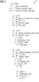
- FIG. 1 are designated with 1 components of a process control system, which in the present embodiment, an operator server 2, an automation device 3 and an operator client 4 include.
- the process control system can of course have a variety of automation devices, which are connected on the one hand via a plant bus 5a with the operator server 2 and on the other hand via a further bus not shown here with decentralized peripherals, to which a plurality of field devices (sensors, actuators) connected are.
- a plant bus 5a with the operator server 2 and on the other hand via a further bus not shown here with decentralized peripherals, to which a plurality of field devices (sensors, actuators) connected are.
- only one operator client 4 and one operator server 2 are shown.
- further operator servers and other OS clients may also be provided, usually in each case an operator server and an operator client connected to this server via a so-called terminal bus 5b form an operator system or an operator station.
- the operator client 4 is provided for representing an equipment hierarchy and plant images, wherein - as explained - an equipment hierarchy next to nodes that represent the plant images, further nodes that represent the process objects.
- an operator can open the corresponding plant picture for display on a display unit by selection or by clicking on a plant picture node, and on the other hand open a faceplate associated with this process object by selection or by clicking on a process object node, whereby the operator displays the process object and thus can serve the plant.
- This faceplate can also be opened by the operator selecting or clicking on a block symbol belonging to this process object in the plant screen.
- FIG. 2 in which an equipment hierarchy (EQH) 6 is shown.
- This equipment hierarchy 6 is created by a user by means of suitable software of an engineering system of the process control system, not shown here, wherein the equipment hierarchy 6 represents a technological view of a technical plant to be controlled.
- this equipment hierarchy 6 are structured according to a tree structure nodes 7, 8 registered or stored, of which the nodes 7 plant images, z. "Display_Overwie_Sub_Plant1" or “Dipslay_Tank1", and nodes 8 represent CFC charts and process objects, such as process objects in the form of monitor and controller objects ("MonAns_Type3", "PID_Type3" ).
- the respective plant image can be opened online, ie during the process control. Selected for this an operator z. B. by means of a "mouse" respectively the corresponding plant picture node 6 of the equipment-client hierarchy 6 shown on the operator-client 4, whereby the system image associated with the selected plant node is opened and displayed on the operator client 4.
- a plant image usually contains graphical icons, for example for tanks, containers, valves, pipes, ..., as well as block icons associated with process objects, the block icons being provided for process monitoring to indicate current process values and parameters during process control.
- the operator can influence the process objects - for example by changing the setpoint and / or other parameters - by first selecting or "clicking on” the displayed block symbols in the plant picture.
- a faceplate of a process object opens for this block symbol and is intended for process control. This faceplate is displayed on the operator client 4, the faceplate having corresponding fields for entering, changing and / or deleting parameters of the process object.
- process object means the respective facets of a process object that are stored in the operator system 2, 4, in a process image 9 of the operator server 2 and in the automation device 3.
- process image 9 of the operator server 2 z. B. to process objects associated process image blocks 10, 11, the automation device 4 associated with these process objects automation blocks 12, 13 and also an interface 14 of the operator system to this process objects associated faceplates and block icons.
- the operator server 2 (FIG. FIG. 1 ) to a (software) component 15, which is adapted to read a message memory 16, in which the messages transmitted by the automation modules to the operator server 2 messages are stored. Based on this information, the component 15 recognizes which process objects generated or caused a message, for example a message in the form of an alarm, warning or diagnostic message.
- the component 15 is configured to read out an access memory 17 in which is deposited, to which process objects of the equipment hierarchy 6 an operator logged on to the operator system 2, 4 can read and / or write. These access rights are usually entered into the access memory 17 during a configuration phase by means of the engineering system. By means of the information as to which process objects generate a message and to which process objects a registered operator is permitted to access, component 15 determines which of the process objects generating a message the logged-in operator is allowed to read and / or write in the equipment hierarchy 6.
- the component 15 is designed to read from a data memory 18 path information 19, 20, which are transmitted from the process image 9 in the data memory 18.
- the paths 19, 20 each describe the path of a process object generating a message within the technological structure of the equipment hierarchy 6, wherein in the present exemplary embodiment it is assumed that these process objects are designed as PID controllers and as monitoring components.
- the component Due to the fact that the component knows the path of these process objects within the equipment hierarchy and has determined or checked whether the logged on operator is allowed to access these process objects at all due to the path information, the component is prepared on an as-needed basis and to dynamically create a procedurally structured plant image personalized for the operators with the block symbols of the process objects generating a message.
- demand-oriented is to be understood that the block icons of a plant picture are only created and updated if the logged-in and authorized access operator at runtime a message node 21, 22 in the equipment hierarchy 6 selects or selects, causing these block icons on the operator client being represented.
- the operator selects the reporting node 21 ("Dynamic Screen:” Alarm "") in the equipment hierarchy 6 (FIG. FIG. 2 ).
- the procedural structuring is - as described - derived from the path information of alarming (alarm message generating) process objects and corresponds to the in the FIG. 2 represented technological hierarchy at runtime (EQH Online).
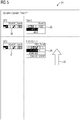
- EQH Online a dynamic system picture 23
- only the block symbols 24 to 31 of the process objects are displayed at runtime, which are alarm-giving and which may also be handled by the operator's access rights by this operator.
- the component 15 reassembles the system image 23 by the component 15 after the operation of the " "block icons in the system screen 23.
- the component 15 immediately reassembles the system image at runtime and generates a" compressed "Plant picture 32 ( FIG. 4 ). Furthermore, the component 15 generates further symbols in the form of horizontal and vertical arrows 33, which indicate the hidden block symbols 27, 28.
- the EQH paths are concatenated accordingly, the path of the process object or the measuring point "Fill1.1” is concatenated under the technical device "Fill1" to "Fill1.Fill1.1", so that the respective process object by the Compressing the "EQH path” has no gaps, which could be annoying regarding the localization of the process object.
- Compression causes all of the block icons to "come together” so that efficient alarm handling is supported without requiring the operator to perform a picture change. If further alarms of the process objects are now handled - for example, all alarms from subsystem "SP1" (Sub Plant 1), the system screen is still dynamically compressed at runtime ( FIG. 5 ).
- the compression of the system image causes the block symbols 24, 25 to be hidden and a compressed system image 34 to be displayed.
Landscapes
- Engineering & Computer Science (AREA)
- Physics & Mathematics (AREA)
- General Physics & Mathematics (AREA)
- Automation & Control Theory (AREA)
- Human Computer Interaction (AREA)
- General Engineering & Computer Science (AREA)
- Manufacturing & Machinery (AREA)
- Quality & Reliability (AREA)
- Testing And Monitoring For Control Systems (AREA)
Abstract
Description
- Die Erfindung betrifft ein Verfahren zum Bedienen und Beobachten einer zu steuernden technischen Anlage gemäß dem Oberbegriff des Anspruchs 1. Die Erfindung betrifft ferner ein Operator-System gemäß dem Oberbegriff des Anspruchs 4 zur Durchführung des Verfahrens.
- In der Prozessleittechnik sind gewöhnlich hunderte von Anlagenbildern und mehrere tausend Prozessobjekte zu bearbeiten, wobei ein Prozessobjekt mehrere zusammengehörige Facetten aufweist. Beispielsweise umfasst ein Prozessabbild eines Servers eines Operator-Systems zu diesen Prozessobjekten gehörige Prozessabbild-Bausteine bzw. bedien- und beobachtungsrelevante Prozessdaten dieser Prozessobjekte, ein Automatisierungsgerät zu den Prozessobjekten gehörige Automatisierungs-bausteine bzw. Steuerbausteine (CFCs, SFCs, ...) und ferner ein User-Interface eines Clients des Operator-Systems zu den Prozessobjekten gehörige Blocksymbole eines Anlagenbildes sowie so genannte Faceplates, wobei die Anlagenbilder, die jeweils grafische Bildsymbole sowie die Blocksymbole der Prozessobjekte umfassen, zur Prozessbeobachtung und die Faceplates zur Prozessführung bzw. Prozessbedienung vorgesehen sind.
- Die Prozessobjekte einer zu steuernden technischen Anlage, z. B. Prozessobjekte in Form von Messstellen, Tanks, Ventile, Sensoren, Aktuatoren, ..., sowie so genannte
Continuous Function Charts (CFCs) und
Sequential Function Charts (SFCs) werden gewöhnlich in einer so genannten Equipment-Hierarchie (EQH) strukturiert, wobei ein Anwender diese Equipment-Hierarchie zunächst mittels einer geeigneten Software eines Engineering-Systems erstellt. Anschließend wird die derart erstellte Equipment-Hierarchie mittels des Engineering-Systems kompiliert und zumindest in einen Operator-Server eines Operator-Systems eines Prozessleitsystems geladen (Compile & Download), wobei zur Laufzeit der Operator-Systeme und der Automatisierungsgeräte bzw. zur Laufzeit des Prozessleitsystems die Equipment-Hierarchie als zentrale Anlaufstelle z. B. für einen Batchprozess oder zur Navigation bzw. zur Ermittlung eines Prozessobjektes innerhalb der Equipment-Hierarchie genutzt wird. Die Equipment-Hierarchie weist neben Knoten, die Anlagenbilder repräsentieren, weitere Knoten auf, welche die Prozessobjekte repräsentieren. Ein Operator kann einerseits durch Selektion bzw. durch Anklicken eines Anlagenbild-Knotens das entsprechende Anlagenbild zur Darstellung auf einer Anzeigeeinheit öffnen, und anderseits durch Selektion bzw. durch Anklicken eines Prozessobjekt-Knotens ein diesem Prozessobjekt zugehöriges Faceplate öffnen, wodurch der Operator das Prozessobjekt und somit die Anlage bedienen kann. Dieses Faceplate kann auch in der Art und Weise geöffnet werden, indem der Operator ein zu diesem Prozessobjekt gehöriges Blocksymbol im Anlagenbild selektiert bzw. anklickt. - Um ein sicheres und effizientes Bedienen und Beobachten einer verfahrenstechnischen Anlage zu bewerkstelligen, ist ein für einen Operator führendes und assistierendes Alarmmanagement von Bedeutung. Bei auftretenden Alarmen, insbesondere bei einem so genannten Alarmschwall, ist es für den Operator im Rahmen der Prozessführung wünschenswert, mit wenigen Eingaben bzw. "Klicks", die jeweiligen Ursachen zu finden, Vorgehensweisen für die Behebung der Alarme abzuleiten und Alarme ohne "Umwege" zu beheben. Insbesondere bei der Behebung von mehreren Alarmen in Folge ist es wichtig, dass der Operator nicht bei jedem Alarm dasselbe "Prozedere" von der Auswahl des zu behebenden Alarms, dessen Lokalisierung und Einordnung und dessen Behebung wiederholen muss.
- Aus dem Siemens-Katalog "ST PCS 7", Kapitel 7, Ausgabe 2017 sind so genannte Meldefolgeanzeigen bekannt, mittels denen zwar Meldungen, z. B. Diagnose-, Warn- und/oder Alarmmeldungen, nach unterschiedlichen Attributen für eine Behandlung tabellenhaft sortiert werden können, allerdings geht durch diese tabellenartige Darstellung die zu Grunde liegende Anlagenstruktur für eine Folgeevaluierung verloren und zur Behebung beispielsweise jeder Alarmmeldung bzw. jeden Alarms muss erst noch zum alarmgebenden Prozessobjekt navigiert werden.
- Der Erfindung liegt daher die Aufgabe zugrunde, ein Verfahren der eingangs genannten Art anzugeben, mittels dessen insbesondere bei Prozessstörungen die Bedienung und Beobachtung einer zu steuernden technischen Anlage vereinfacht wird. Darüber hinaus ist ein Operator-System gemäß dem Oberbegriff des Anspruchs 4 zu schaffen, welches zur Durchführung des Verfahrens geeignet ist.
- Diese Aufgabe wird im Hinblick auf das Verfahren durch die im kennzeichnenden Teil des Anspruchs 1 angegebenen, bezüglich des Operator-Systems durch die im kennzeichnenden Teil des Anspruchs 4 angegebenen Maßnahmen gelöst.
- Vorteilhaft ist, dass strukturierte, personalisierte und zur Laufzeit dynamisch zusammengestellte Blocksymbole von Anlagenbildern erzeugt werden, welche beispielsweise eine effizient geführte und assistierte Behandlung von Alarmmeldungen durch einen Operator ermöglichen. Darüber hinaus wird durch eine dynamisch aktualisierte Darstellung von alarmgebenden Prozessobjekten gemäß einer Equipment-Hierarchie eine Evaluierung von Alarmschwallverursachern ermöglicht.
- In einer Ausgestaltung der Erfindung gemäß den im Anspruch 2 angegebenen Maßnahmen kann der Operator die Lage bzw. Gefahrensituation bezüglich der verfahrenstechnischen Anlage besser einschätzen, indem die Anzahl der dargestellten Blocksymbole der Anlagenbilder "schrumpft" oder "wächst". Beispielsweise weist eine wachsende Anzahl auf steigende Störungen und somit auf viele zu behandelnde Prozessobjekte, eine schrumpfende Anzahl weist dagegen auf wenige Störungen und somit auf wenige zu behandelnde Prozessobjekte hin. Für den Fall, dass keine Blocksymbole mehr angezeigt werden, sind für den Operator keine aktiven Meldungen, Alarme bzw. Alarmmeldungen von Prozessobjekten mehr vorhanden, die er gemäß seinen Zugriffrechten behandeln müsste. Durch eine derartige dynamische Darstellung der Blocksymbole in Anlagenbildern ist die Quantität von Alarmen unmittelbar für den zugriffsberechtigten Operator "erfassbar", wobei auch die Tendenz hin zu weniger oder mehr Alarmen unmittelbar durch Schrumpfen oder Wachsen der Anzahl der dargestellten Blocksymbole der Anlagenbilder wahrgenommen werden kann.
- In einer weiteren Ausgestaltung der Erfindung werden zusätzlich zu den dargestellten Blocksymbolen weitere Symbole im Anlagenbild, z. B. Symbole in Form von horizontalen und/oder vertikalen Pfeilen, dargestellt, die auf ausgeblendete Block-symbole hinweisen. Dadurch wird dem Operator die "Kompression" der Blocksymbole angezeigt.
- Anhand der Zeichnung, in der ein Ausführungsbeispiel der Erfindung veranschaulicht ist, werden im Folgenden die Erfindung, deren Ausgestaltungen sowie Vorteile näher erläutert.
- Es zeigen in einer vereinfachten Form:
- Figur 1
- Bestandteile eines Prozessleitsystems,
- Figur 2
- eine Equipment-Hierarchie und
- Figur 3 bis 5
- Blocksymbole eines Anlagenbildes.
- Die in den
Figuren 1 bis 5 dargestellten gleichen Teile sind mit gleichen Bezugszeichen versehen. - In
Figur 1 sind mit 1 Bestandteile eines Prozessleitsystems bezeichnet, die im vorliegenden Ausführungsbeispiel einen Operator-Server 2, ein Automatisierungsgerät 3 und einen Operator-Client 4 umfassen. Das Prozessleitsystem kann selbstverständlich eine Vielzahl von Automatisierungsgeräten aufweisen, die einerseits über einen Plant Bus 5a mit dem Operator-Server 2 und andererseits über einen weiteren hier nicht dargestellten Bus mit dezentralen Peripherien verbunden sind, an welche eine Vielzahl von Feldgeräten (Sensoren, Aktuatoren) angeschlossen sind. Im vorliegenden Beispiel sind lediglich ein Operator-Client 4 und ein Operator-Server 2 dargestellt. Selbstverständlich können ferner weitere Operator-Server und weitere OS-Clients vorgesehen sein, wobei gewöhnlich jeweils ein Operator-Server und ein über einen so genannten Terminal Bus 5b mit diesem Server verbundener Operator-Client ein Operator-System bzw. eine Operator-Station bilden. - Der Operator-Client 4 ist zur Darstellung einer Equipment-Hierarchie und von Anlagenbildern vorgesehen, wobei - wie erläutert - eine Equipment-Hierarchie neben Knoten, welche die Anlagenbilder repräsentieren, weitere Knoten aufweist, welche die Prozessobjekte repräsentieren. Ein Operator kann einerseits durch Selektion bzw. durch Anklicken eines Anlagenbild-Knotens das entsprechende Anlagenbild zur Darstellung auf einer Anzeigeeinheit öffnen, und anderseits durch Selektion bzw. durch Anklicken eines Prozessobjekt-Knotens ein diesem Prozessobjekt zugehöriges Faceplate öffnen, wodurch der Operator das Prozessobjekt und somit die Anlage bedienen kann. Dieses Faceplate kann ferner dadurch geöffnet werden, indem der Operator ein zu diesem Prozessobjekt gehöriges Blocksymbol im Anlagenbild selektiert bzw. anklickt.
- Im Folgenden wird auf
Figur 2 verwiesen, in welcher eine Equipment-Hierarchie (EQH) 6 dargestellt ist. Diese Equipment-Hierarchie 6 erstellt ein Anwender mittels einer geeigneten Software eines hier nicht dargestellten Engineering-Systems des Prozessleitsystems, wobei die Equipment-Hierarchie 6 eine technologische Sicht einer zu steuernden technischen Anlage (Plant) repräsentiert. In dieser Equipment-Hierarchie 6 sind strukturiert gemäß einer Baumstruktur Knoten 7, 8 eingetragen bzw. hinterlegt, von denen die Knoten 7 Anlagenbilder, z. B. "Display_Overwie_Sub_Plant1" oder "Dipslay_Tank1", und die Knoten 8 CFC-Pläne und Prozessobjekte, beispielsweise Prozessobjekte in Form von Überwachungs- und Reglerobjekten ("MonAns_Type3", "PID_Type3" ...), repräsentieren. - Mittels der durch das Engineering-System erstellten und nach der Kompilierung in das Operator-System geladenen Equipment-Hierarchie 6 kann das jeweilige Anlagenbild online, d. h. während der Prozesssteuerung - geöffnet werden. Dazu selektiert ein Operator z. B. mittels einer "Maus" jeweils den entsprechenden Anlagenbild-Knoten 6 der auf dem Operator-Client 4 dargestellten Equipment-Hierarchie 6, wodurch das dem selektierten Anlagen-Knoten zugehörige Anlagenbild geöffnet und auf dem Operator-Client 4 dargestellt wird. Ein derartiges Anlagenbild enthält gewöhnlich grafische Bildsymbole, beispielsweise für Tanks, Behälter, Ventile, Rohre, ..., sowie zu Prozessobjekten gehörige Block-Symbole, wobei die Block-Symbole zur Prozessbeobachtung vorgesehen sind, um aktuelle Prozesswerte und Parameter während der Prozesssteuerung anzuzeigen.
- Im Hinblick auf eine Prozessführung kann der Operator die Prozessobjekte - beispielsweise durch Ändern des Sollwerts und/oder weiteren Parameter - beeinflussen, indem er zunächst die angezeigten Block-Symbole im Anlagenbild selektiert bzw. "anklickt". Für den Fall, dass der Operator ein Blocksymbol selektiert, öffnet sich ein zu diesem Block-Symbol gehöriges, zur Prozessführung vorgesehenes, hier nicht dargestelltes Faceplate eines Prozessobjektes. Dieses Faceplate wird auf dem Operator-Client 4 dargestellt, wobei das Faceplate entsprechende Felder zum Eingeben, Ändern und/oder Löschen von Parametern des Prozessobjektes aufweist.
- Es wird darauf hingewiesen, dass unter dem Begriff "Prozessobjekt" die jeweiligen Facetten eines Prozessobjektes verstanden werden, die im Operator-System 2, 4, in einem Prozessabbild 9 des Operator-Servers 2 und im Automatisierungsgerät 3 hinterlegt sind. So weist das Prozessabbild 9 des Operator-Servers 2 z. B. zu Prozessobjekten gehörige Prozessabbild-Bausteine 10, 11, das Automatisierungsgerät 4 zu diesen Prozessobjekten gehörige Automatisierungsbausteine 12, 13 und ferner ein Interface 14 des Operator-Systems zu diesem Prozessobjekten gehörige Faceplates und Blocksymbole auf.
- Um die Bedienung und Beobachtung einer zu steuernden technischen Anlage zu vereinfachen und um verfahrenstechnisch strukturierte, personalisierte und zur Laufzeit dynamisch zusammengestellte Anlagenbilder oder Teile von Anlagenbildern von eine Meldung erzeugenden Prozessobjekten bereitstellen zu können, weist der Operator-Server 2 (
Figur 1 ) eine (Software-)Komponente 15 auf, die dazu ausgebildet ist, einen Meldespeicher 16 auszulesen, in welchem die von den Automatisierungs-Bausteinen dem Operator-Server 2 übermittelten Meldungen hinterlegt sind. Aufgrund dieser Information erkennt die Komponente 15, welche Prozessobjekte eine Meldung erzeugten bzw. verursachten, beispielsweise eine Meldung in Form einer Alarm-, Warnung- oder Diagnosemeldung. - Ferner ist die Komponente 15 dazu ausgebildet, einen Zugriffsspeicher 17 auszulesen, in welchem hinterlegt ist, auf welche Prozessobjekte der Equipment-Hierarchie 6 ein an dem Operator-System 2, 4 angemeldeter Operator lesend und/oder schreibend zugreifen darf. Diese Zugriffrechte werden gewöhnlich während einer Projektierungsphase mittels des Engineering-Systems in den Zugriffsspeicher 17 eingetragen. Mittels der Informationen, welche Prozessobjekte eine Meldung erzeugen und auf welche Prozessobjekte ein angemeldeter Operator zugreifen darf, ermittelt die Komponente 15, auf welche der eine Meldung erzeugenden Prozessobjekte der angemeldete Operator in der Equipment-Hierarchie 6 lesend und/oder schreibend zugreifen darf.
- Darüber hinaus ist die Komponente 15 dazu ausgebildet, aus einem Datenspeicher 18 Pfadangaben 19, 20 auszulesen, die vom Prozessabbild 9 in den Datenspeicher 18 übertragen werden. Die Pfadangaben 19, 20 beschreiben jeweils den Pfad eines eine Meldung erzeugenden Prozessobjektes innerhalb der technologischen Struktur der Equipment-Hierarchie 6, wobei im vorliegenden Ausführungsbeispiel angenommen wird, dass diese Prozessobjekte als PID-Regler und als Überwachungs-Baustein ausgebildet sind.
- Dadurch, dass die Komponente aufgrund der Pfadangaben den Pfad dieser Prozessobjekte innerhalb der Equipment-Hierarchie kennt und darüber ermittelt bzw. geprüft hat, ob der angemeldete Operator auf diese Prozessobjekte überhaupt zugreifen darf, ist die Komponente dazu vorbereitet, bedarfsorientiert und dynamisch ein verfahrenstechnisch strukturiertes, für den Operatoren personalisiertes Anlagenbild mit den Blocksymbolen der eine Meldung erzeugenden Prozessobjekte zu erstellen. Unter bedarfsorientiert ist zu verstehen, dass die Blocksymbole eines Anlagenbildes erst erstellt und aktualisiert werden, falls der angemeldete und zugriffsberechtigte Operator zur Laufzeit einen Meldeknoten 21, 22 in der Equipment-Hierarchie 6 selektiert bzw. anwählt, wodurch diese Blocksymbole auf dem Operator-Client 4 dargestellt werden.
- Für den Fall, dass der angemeldete Operator die Prozessobjekte beobachten und bedienen möchte, die eine Meldung in Form eines Alarms erzeugten, selektiert der Operator den Meldeknoten 21 ("Dynamic Screen: "Alarm"") in der Equipment-Hierarchie 6 (
Figur 2 ). Die verfahrenstechnische Strukturierung wird - wie beschrieben - aus den Pfadangaben der alarmgebenden (Alarm-Meldung erzeugenden) Prozessobjekte abgeleitet und entspricht der in derFigur 2 dargestellten technologischen Hierarchie zur Laufzeit (EQH Online). In einem dynamischen Anlagenbild 23 (Figur 3 ) werden dann zur Laufzeit nur die Block-Symbole 24 bis 31 der Prozessobjekte angezeigt, die alarmgebend sind und die durch die Zugriffsrechte des Operators von diesem Operator auch behandelt werden dürfen. - Für den Fall, dass nun durch den Operator die alarmgebenden Prozessobjekte bedient werden, indem der Operator die dazugehörigen Blocksymbole zunächst selektiert und anschließend sich öffnende zugehörige Faceplates bearbeitet, stellt die Komponente 15 das Anlagenbild 23 neu zusammen, indem die Komponente 15 nach der Bedienung die "bedienten" Blocksymbole im Anlagenbild 23 ausblendet.
- Werden beispielsweise die Alarme der dargestellten Blocksymbole 27, 28 ("PIDL_Type3" aus "Tank2" und ""PICStopL_Type3" aus "Fill1") der alarmgebenden Prozessobjekte behandelt, so stellt die Komponente 15 das Anlagenbild zur Laufzeit unmittelbar neu zusammen und erzeugt ein "komprimiertes" Anlagenbild 32 (
Figur 4 ). Ferner erzeugt die Komponente 15 weitere Symbole in Form von horizontalen und vertikalen Pfeilen 33, die auf die ausgeblendeten Blocksymbole 27, 28 hinweisen. Durch eine derartige Komprimierung werden die EQH-Pfade entsprechend konkateniert, der Pfad des Prozessobjektes bzw. der Messstelle "Fill1.1" wird unter der technischen Einrichtung "Fill1" zu "Fill1.Fill1.1" konkateniert, so dass zum jeweiligen Prozessobjekt durch die Komprimierung der "EQH-Pfad" keine Lücken aufweist, was störend bezüglich der Lokalisierung des Prozessobjekts sein könnte. Durch die Komprimierung rücken alle Blocksymbole "zusammen", so dass eine effiziente Alarmbehandlung unterstützt wird, ohne dass der Operator dazu einen Bildwechsel vollziehen muss. Werden nun weitere Alarme der Prozessobjekte behandelt - beispielsweise alle Alarme aus der Teilanlage "SP1" (Sub Plant 1), wird das Anlagenbild weiterhin zur Laufzeit dynamisch komprimiert (Figur 5 ). Die Komprimierung des Anlagenbildes bewirkt, dass die Blocksymbole 24, 25 ausgeblendet und ein komprimiertes Anlagenbild 34 dargestellt wird. - Weist ein dargestelltes Anlagenbild keine Blocksymbole mehr auf, so weist dies darauf hin, dass für den Operator gemäß seinen Zugriffsrechten keine weiteren aktiven Alarme von Prozessobjekten mehr vorhanden sind, die er behandeln müsste.
- Durch eine derartige dynamische Darstellung im Anlagenbild, ist die Quantität der Alarme unmittelbar "erfassbar". Auch die Tendenz hin zu weniger und mehr Alarmen kann unmittelbar durch Schrumpfen oder Wachsen des Anlagenbildes wahrgenommen werden. Vorteilhaft dieser dynamischen Darstellung von aktiven Alarmen ist, dass der Operator auf Grundlage der visuell strukturierten Darstellung angelehnt an die Equipment-Hierarchie Zusammenhänge zwischen Prozessobjekten und Alarmen erkennen und eine Strategie zur Alarmbehandlung entwickeln kann. Aufgrund der Verkettung von Prozessobjekten wird gewöhnlich von einem dieser Prozessobjekte als Verursacher ein Schwall von Alarmen ausgelöst. Durch diese beschriebene dynamische und strukturierte Darstellung ist es dem Operator möglich, die Quelle eines Alarmschwalls zu erkennen und zu behandeln. Oftmals ist ein hochpriorer Alarm nicht auch die unmittelbare Ursache für einen Alarmschwall, so dass dessen Behebung auch nicht zur Behebung des Alarmschwalls beiträgt. Mittels der beschriebenen Maßnahmen wird die Möglichkeit geschaffen, die Ursache eines Alarmschwalls rasch zu erkennen.
Claims (6)
- Verfahren zum Bedienen und Beobachten einer zu steuernden technischen Anlage, wobei- in einen Operator-Server (2) des Operator-Systems (2, 4) Zugriffsberechtigungen hinterlegt werden, die beschreiben, auf welche Prozessobjekte ein an diesem Operator-System (2, 4) angemeldeter Operator lesend und/oder schreibend zugreifen darf,- in dem Operator-Server (2) ein Prozessabbild (9) hinterlegt wird, das zu den Prozessobjekten gehörige Prozessabbild-Bausteine (10, 11) aufweist,- in den Operator-Server (2) zu den Prozessobjekten gehörige Block-Symbole (24 bis 31) von Anlagenbildern sowie zu den Prozessobjekten gehörige Faceplates hinterlegt werden,- zum Öffnen des jeweiligen Anlagenbildes zur Darstellung auf einem Operator-Client (4) des Operator-Systems (2, 4) in einer Equipment-Hierarchie (6) für das jeweilige Anlagenbild ein durch einen Operator selektierbarer Knoten (7) eingetragen wird,- in ein Automatisierungsgerät (3) zu den Prozessobjekten gehörige Automatisierungs-Bausteine (12, 13) hinterlegt werden, wobei zur Laufzeit des Automatisierungsgerätes (3) die Automatisierungs-Bausteine dem Operator-Server (2) Meldungen übermitteln,dadurch gekennzeichnet, dass für den Fall, dass dem Operator-Server (2) Meldungen übermittelt werden,- anhand der Meldungen ermittelt wird, welche der Prozessobjekte Meldungen erzeugen,- anhand der hinterlegten Zugriffsberechtigungen ermittelt wird, ob der an dem Operator-System (2, 4) angemeldete Operator berechtigt ist, auf dieses die Meldung erzeugende Prozessobjekt zuzugreifen,- in den jeweiligen Prozessabbild-Bausteinen (10, 11) eine Pfadangabe (19, 20) ausgelesen wird, die den Pfad des eine Meldung erzeugenden Prozessobjektes in der Equipment-Hierarchie (6) beschreibt, und- für den Fall, dass der angemeldete Operator berechtigt ist, die die Meldung erzeugende Prozessobjekte zu bedienen, und für den Fall, dass ein Melde-Knoten (21, 22) in der Equipment-Hierarchie (6) durch den angemeldeten Operator selektiert wird, die Blocksymbole der die Meldung erzeugenden Prozessobjekte dargestellt werden.
- Verfahren nach Anspruch 1, dadurch gekennzeichnet, dass für den Fall, dass das dargestellte Blocksymbol (27, 28) der jeweiligen eine Meldung erzeugenden Prozessobjekte durch den Operator selektiert wird, das zu diesem Blocksymbol gehörige Faceplate zum Bedienen des Prozessobjektes geöffnet wird, wobei nach der Bedienung das Faceplate und das Blocksymbol (27, 28) ausgeblendet wird.
- Verfahren nach Anspruch 2, dadurch gekennzeichnet, dass zusätzlich zu den dargestellten Blocksymbolen weitere Symbole (33) dargestellt werden, die auf ausgeblendete Blocksymbole (27, 28) hinweisen.
- Operator-System für ein Prozessleitsystem, wobei- in einem Operator-Server (2) des Operator-Systems (2, 4) Zugriffsberechtigungen hinterlegt sind, die beschreiben, auf welche Prozessobjekte ein an diesem Operator-System (2, 4) angemeldeter Operator lesend und/oder schreibend zugreifen darf,- in dem Operator-Server (2) ein Prozessabbild (9) hinterlegt ist, das zu den Prozessobjekten gehörige Prozessabbild-Bausteine (10, 11) aufweist,- in den Operator-Server (2) zu den Prozessobjekten gehörige Block-Symbole (24 bis 31) von Anlagenbildern sowie zu den Prozessobjekten gehörige Faceplates hinterlegt sind,- zum Öffnen des jeweiligen Anlagenbildes zur Darstellung auf einem Operator-Client (4) des Operator-Systems (2, 4) in einer Equipment-Hierarchie (6) für das jeweilige Anlagenbild ein durch einen Operator selektierbarer Knoten (7) eingetragen ist,- der Operator-Server dazu ausgebildet ist, von einem Automatisierungsgerät (3), in welchem zu den Prozessobjekten gehörige Automatisierungs-Bausteine (12, 13) hinterlegt sind, zur Laufzeit des Automatisierungsgerätes (3) von den Automatisierungs-Bausteinen (12, 13) Meldungen zu empfangen,dadurch gekennzeichnet, dass das Operator-System (4) dazu ausgebildet ist, für den Fall, dass von dem Operator-Server (2) Meldungen empfangen werden,- anhand der Meldungen zu ermitteln, welche der jeweiligen Prozessobjekte eine Meldung erzeugen,- anhand der hinterlegten Zugriffsberechtigungen zu ermitteln, ob der an dem Operator-System (2, 4) angemeldete Operator berechtigt ist, auf dieses die Meldung erzeugende Prozessobjekt zuzugreifen,- in den jeweiligen Prozessabbild-Bausteinen (10, 11) eine Pfadangabe (19, 20) auszulesen, die den Pfad des eine Meldung erzeugenden Prozessobjektes in der Equipment-Hierarchie (6) beschreibt,- für den Fall, dass der angemeldete Operator berechtigt ist, die die Meldung erzeugenden Prozessobjekte zu bedienen, und für den Fall, dass der angemeldete Operator einen Melde-Knoten (21, 22) in der Equipment-Hierarchie (6) selektiert, die Blocksymbole der die Meldung erzeugenden Prozessobjekte darzustellen.
- Operator-System nach Anspruch 4, dadurch gekennzeichnet, dass das Operator-System (2, 4) ferner dazu ausgebildet ist, für den Fall, dass das dargestellte Blocksymbol (27, 28) der jeweiligen die Meldung erzeugenden Prozessobjekte durch den Operator selektiert wird, das zu diesem Blocksymbol (27, 28) gehörige Faceplate zum Bedienen des Prozessobjektes zu öffnen und nach der Bedienung das Faceplate und das Blocksymbol (27, 28) auszublenden.
- Operator-System nach Anspruch 5, dadurch gekennzeichnet, dass das Operator-System (4) dazu ausgebildet ist, zusätzlich zu den dargestellten Blocksymbolen weitere Symbole (33) darzustellen, die auf ausgeblendete Blocksymbole (27, 28) hinweisen.
Priority Applications (3)
| Application Number | Priority Date | Filing Date | Title |
|---|---|---|---|
| EP17205492.6A EP3495903B1 (de) | 2017-12-05 | 2017-12-05 | Verfahren zum bedienen und beobachten einer zu steuernden technischen anlage sowie operator-system |
| CN201811073286.0A CN109871670B (zh) | 2017-12-05 | 2018-09-14 | 操作和监视需要控制的工业设备的方法以及操作员系统 |
| US16/209,342 US10845790B2 (en) | 2017-12-05 | 2018-12-04 | Operator system and method for operating and observing a technical plant to be controlled |
Applications Claiming Priority (1)
| Application Number | Priority Date | Filing Date | Title |
|---|---|---|---|
| EP17205492.6A EP3495903B1 (de) | 2017-12-05 | 2017-12-05 | Verfahren zum bedienen und beobachten einer zu steuernden technischen anlage sowie operator-system |
Publications (2)
| Publication Number | Publication Date |
|---|---|
| EP3495903A1 true EP3495903A1 (de) | 2019-06-12 |
| EP3495903B1 EP3495903B1 (de) | 2020-02-26 |
Family
ID=60661766
Family Applications (1)
| Application Number | Title | Priority Date | Filing Date |
|---|---|---|---|
| EP17205492.6A Active EP3495903B1 (de) | 2017-12-05 | 2017-12-05 | Verfahren zum bedienen und beobachten einer zu steuernden technischen anlage sowie operator-system |
Country Status (3)
| Country | Link |
|---|---|
| US (1) | US10845790B2 (de) |
| EP (1) | EP3495903B1 (de) |
| CN (1) | CN109871670B (de) |
Cited By (7)
| Publication number | Priority date | Publication date | Assignee | Title |
|---|---|---|---|---|
| EP3855266A1 (de) * | 2020-01-22 | 2021-07-28 | Siemens Aktiengesellschaft | Verfahren zum verarbeiten von alarmen in einem leitsystem einer technischen anlage |
| EP4089489A1 (de) * | 2021-05-12 | 2022-11-16 | Siemens Aktiengesellschaft | Leitsystem für eine technische anlage |
| EP4137900A1 (de) * | 2021-08-18 | 2023-02-22 | Siemens Aktiengesellschaft | Alarmassoziierte container in anlagenbildern technischer anlagen |
| EP4390591A1 (de) * | 2022-12-19 | 2024-06-26 | Siemens Aktiengesellschaft | Verfahren zur überwachung von alarmen in einem prozessautomatisierungssystem und prozessleitsystem |
| EP4471520A1 (de) * | 2023-05-31 | 2024-12-04 | Siemens Aktiengesellschaft | Lokalisierung eines operators innerhalb einer technischen anlage |
| EP4478137A1 (de) * | 2023-06-12 | 2024-12-18 | Siemens Aktiengesellschaft | Leitsystem für eine technische anlage |
| EP4592782A1 (de) * | 2024-01-24 | 2025-07-30 | Siemens Aktiengesellschaft | Zentralisation der bedienung und beobachtung |
Families Citing this family (8)
| Publication number | Priority date | Publication date | Assignee | Title |
|---|---|---|---|---|
| EP3736647A1 (de) * | 2019-05-07 | 2020-11-11 | Siemens Aktiengesellschaft | Abhängigkeiten zwischen prozessobjekten |
| EP3805882B1 (de) * | 2019-10-10 | 2022-06-08 | Siemens Aktiengesellschaft | Leitsystem für eine technische anlage mit trendkurvendiagramm |
| JP6734985B1 (ja) * | 2019-10-31 | 2020-08-05 | 株式会社 日立産業制御ソリューションズ | 業務管理システム及び業務管理方法 |
| EP3929679A1 (de) * | 2020-06-23 | 2021-12-29 | ABB Schweiz AG | Engineering-system für orchestration einer industrieanlage |
| EP3968107B1 (de) * | 2020-09-09 | 2022-12-14 | Siemens Aktiengesellschaft | Prozessüberwachungssystem und verfahren zum betrieb eines prozessüberwachungssystems |
| EP4047433B1 (de) * | 2021-02-23 | 2025-10-01 | Siemens Aktiengesellschaft | Konfigurierbare notifikationen über zustandsänderungen von technischen objekten |
| JP2022154865A (ja) * | 2021-03-30 | 2022-10-13 | 富士通株式会社 | 画面生成支援プログラム、装置、及び方法 |
| EP4095634A1 (de) | 2021-05-26 | 2022-11-30 | Siemens Aktiengesellschaft | Leitsystem für eine technische anlage |
Citations (3)
| Publication number | Priority date | Publication date | Assignee | Title |
|---|---|---|---|---|
| US20050027377A1 (en) * | 2003-02-18 | 2005-02-03 | Fisher-Rosemount Systems, Inc. | Version control for objects in a process plant configuration system |
| EP2124114A1 (de) * | 2008-05-23 | 2009-11-25 | Siemens Aktiengesellschaft | Verfahren zur Auswahl von auf einem Operator-System dargestellten Objekten |
| EP2808749A1 (de) * | 2013-05-29 | 2014-12-03 | Siemens Aktiengesellschaft | Verfahren zum Austausch von Steuerungsinformationen zwischen Bedien- und Beobachtungsgeräten eines industriellen Automatisierungssystems und industrielles Automatisierungssystem |
Family Cites Families (4)
| Publication number | Priority date | Publication date | Assignee | Title |
|---|---|---|---|---|
| US7526347B2 (en) * | 2003-02-18 | 2009-04-28 | Fisher-Rosemount Systems, Inc. | Security for objects in a process plant configuration system |
| CN102405448B (zh) * | 2009-04-20 | 2015-09-09 | Abb研究有限公司 | 过程控制系统中的操作员终端 |
| US10013149B2 (en) * | 2013-03-15 | 2018-07-03 | Fisher-Rosemount Systems, Inc. | Graphical process variable trend monitoring for a process control system |
| US20170205795A1 (en) * | 2016-01-15 | 2017-07-20 | Yokogawa Electric Corporation | Method for process operators to personalize settings for enabling detection of abnormal process behaviors |
-
2017
- 2017-12-05 EP EP17205492.6A patent/EP3495903B1/de active Active
-
2018
- 2018-09-14 CN CN201811073286.0A patent/CN109871670B/zh not_active Expired - Fee Related
- 2018-12-04 US US16/209,342 patent/US10845790B2/en active Active
Patent Citations (3)
| Publication number | Priority date | Publication date | Assignee | Title |
|---|---|---|---|---|
| US20050027377A1 (en) * | 2003-02-18 | 2005-02-03 | Fisher-Rosemount Systems, Inc. | Version control for objects in a process plant configuration system |
| EP2124114A1 (de) * | 2008-05-23 | 2009-11-25 | Siemens Aktiengesellschaft | Verfahren zur Auswahl von auf einem Operator-System dargestellten Objekten |
| EP2808749A1 (de) * | 2013-05-29 | 2014-12-03 | Siemens Aktiengesellschaft | Verfahren zum Austausch von Steuerungsinformationen zwischen Bedien- und Beobachtungsgeräten eines industriellen Automatisierungssystems und industrielles Automatisierungssystem |
Non-Patent Citations (1)
| Title |
|---|
| "Aus dem Siemens-Katalog", August 2017, article "ST PCS 7" |
Cited By (10)
| Publication number | Priority date | Publication date | Assignee | Title |
|---|---|---|---|---|
| EP3855266A1 (de) * | 2020-01-22 | 2021-07-28 | Siemens Aktiengesellschaft | Verfahren zum verarbeiten von alarmen in einem leitsystem einer technischen anlage |
| EP4089489A1 (de) * | 2021-05-12 | 2022-11-16 | Siemens Aktiengesellschaft | Leitsystem für eine technische anlage |
| WO2022238496A1 (de) * | 2021-05-12 | 2022-11-17 | Siemens Aktiengesellschaft | Leitsystem für eine technische anlage |
| EP4137900A1 (de) * | 2021-08-18 | 2023-02-22 | Siemens Aktiengesellschaft | Alarmassoziierte container in anlagenbildern technischer anlagen |
| WO2023021041A1 (de) * | 2021-08-18 | 2023-02-23 | Siemens Aktiengesellschaft | Alarmassoziierte container in anlagenbildern technischer anlagen |
| EP4390591A1 (de) * | 2022-12-19 | 2024-06-26 | Siemens Aktiengesellschaft | Verfahren zur überwachung von alarmen in einem prozessautomatisierungssystem und prozessleitsystem |
| EP4471520A1 (de) * | 2023-05-31 | 2024-12-04 | Siemens Aktiengesellschaft | Lokalisierung eines operators innerhalb einer technischen anlage |
| WO2024245618A1 (de) * | 2023-05-31 | 2024-12-05 | Siemens Aktiengesellschaft | Lokalisierung eines operators innerhalb einer technischen anlage |
| EP4478137A1 (de) * | 2023-06-12 | 2024-12-18 | Siemens Aktiengesellschaft | Leitsystem für eine technische anlage |
| EP4592782A1 (de) * | 2024-01-24 | 2025-07-30 | Siemens Aktiengesellschaft | Zentralisation der bedienung und beobachtung |
Also Published As
| Publication number | Publication date |
|---|---|
| EP3495903B1 (de) | 2020-02-26 |
| US10845790B2 (en) | 2020-11-24 |
| CN109871670A (zh) | 2019-06-11 |
| CN109871670B (zh) | 2023-05-30 |
| US20190171196A1 (en) | 2019-06-06 |
Similar Documents
| Publication | Publication Date | Title |
|---|---|---|
| EP3495903B1 (de) | Verfahren zum bedienen und beobachten einer zu steuernden technischen anlage sowie operator-system | |
| EP3480672B1 (de) | Verfahren zum erkennen und anzeigen von operator-zugriffen auf prozessobjekte sowie operator-system | |
| EP1330685B1 (de) | Prüfverfahren und prüfvorrichtung zur inbetriebnahme von mittels einer programmlogik gesteuerten systemen | |
| EP3528074B1 (de) | Verfahren zum überprüfen der beziehung zwischen einem visuell auf einem operator-client eines prozessleitsystems dargestellten und einem akustisch ausgegebenen prozessalarm eines prozessobjektes sowie operator-system | |
| DE69222821T2 (de) | Genereller Datenaustausch | |
| EP3623891A1 (de) | Individualisierbare bildhierarchien für ein leitsystem einer technischen anlage | |
| DE102015122002A1 (de) | Verfahren und Apparatur zur Bereitstellung einer rollenbasierten Benutzerschnittstelle | |
| EP3508928A1 (de) | Verfahren zum verarbeiten von alarmen in einem prozessleitsystem sowie operator-system | |
| WO2009047193A1 (de) | Verfahren zum bedienen von feldgeräten der prozessautomatisierungstechnik mit einem geräteunabhängigen bedienprogramm | |
| EP3598255B1 (de) | Anordnung mit operator-servern und mit operator-clients | |
| DE102020127820A1 (de) | Technologien zum konfigurieren von abstimmungsblöcken, die einem prozesssteuerungssystem zugeordnet sind | |
| EP3276437A1 (de) | Verfahren zum betreiben eines automatisierungssystems, bedien- und beobachtungssystem und automatisierungssystem | |
| EP2808749B1 (de) | Verfahren zum Austausch von Steuerungsinformationen zwischen Bedien- und Beobachtungsgeräten eines industriellen Automatisierungssystems und industrielles Automatisierungssystem | |
| EP4370986B1 (de) | Leitsystem für eine technische anlage mit verkleinerten ansichten von anlagenbildern | |
| EP3680740A1 (de) | Anzeige von objekten als folge der selektion einer alarmmeldung | |
| EP4390591A1 (de) | Verfahren zur überwachung von alarmen in einem prozessautomatisierungssystem und prozessleitsystem | |
| EP3396479B1 (de) | Engineering-system | |
| EP3964905A1 (de) | Nutzerspezifische abhängigkeiten zwischen digitalen repräsentationen von prozessobjekten | |
| EP1092210A1 (de) | Vorrichtung und verfahren zur erstellung eines virtuellen anlagenmodells | |
| EP4099114A1 (de) | Verfahren zum erkennen einer eingeschränkten bedienung und beobachtung einer technischen anlage, bedien- und beobachtungssystem und prozessleitsystem | |
| EP4092502A1 (de) | Leitsystem für eine technische anlage mit trendkurvendiagramm | |
| DE102017123910A1 (de) | Verfahren und Vorrichtung zum Überwachen der Sicherheitsintegrität einer durch ein Sicherheitssystem bereitgestellten Sicherheitsfunktion | |
| WO2022084452A1 (de) | Verfahren zum betreiben eines automatisierungssystems einer maschine oder einer anlage | |
| EP3617825A1 (de) | Automatisierte evaluierung von alarmhäufungen | |
| EP4341759B1 (de) | Alarmassoziierte container in anlagenbildern technischer anlagen |
Legal Events
| Date | Code | Title | Description |
|---|---|---|---|
| PUAI | Public reference made under article 153(3) epc to a published international application that has entered the european phase |
Free format text: ORIGINAL CODE: 0009012 |
|
| STAA | Information on the status of an ep patent application or granted ep patent |
Free format text: STATUS: REQUEST FOR EXAMINATION WAS MADE |
|
| 17P | Request for examination filed |
Effective date: 20180705 |
|
| AK | Designated contracting states |
Kind code of ref document: A1 Designated state(s): AL AT BE BG CH CY CZ DE DK EE ES FI FR GB GR HR HU IE IS IT LI LT LU LV MC MK MT NL NO PL PT RO RS SE SI SK SM TR |
|
| AX | Request for extension of the european patent |
Extension state: BA ME |
|
| REG | Reference to a national code |
Ref country code: DE Ref legal event code: R079 Ref document number: 502017003959 Country of ref document: DE Free format text: PREVIOUS MAIN CLASS: G05B0019418000 Ipc: G05B0023020000 |
|
| GRAP | Despatch of communication of intention to grant a patent |
Free format text: ORIGINAL CODE: EPIDOSNIGR1 |
|
| STAA | Information on the status of an ep patent application or granted ep patent |
Free format text: STATUS: GRANT OF PATENT IS INTENDED |
|
| RIC1 | Information provided on ipc code assigned before grant |
Ipc: G05B 23/02 20060101AFI20191018BHEP |
|
| INTG | Intention to grant announced |
Effective date: 20191115 |
|
| GRAS | Grant fee paid |
Free format text: ORIGINAL CODE: EPIDOSNIGR3 |
|
| GRAA | (expected) grant |
Free format text: ORIGINAL CODE: 0009210 |
|
| STAA | Information on the status of an ep patent application or granted ep patent |
Free format text: STATUS: THE PATENT HAS BEEN GRANTED |
|
| AK | Designated contracting states |
Kind code of ref document: B1 Designated state(s): AL AT BE BG CH CY CZ DE DK EE ES FI FR GB GR HR HU IE IS IT LI LT LU LV MC MK MT NL NO PL PT RO RS SE SI SK SM TR |
|
| REG | Reference to a national code |
Ref country code: GB Ref legal event code: FG4D Free format text: NOT ENGLISH |
|
| REG | Reference to a national code |
Ref country code: CH Ref legal event code: EP |
|
| REG | Reference to a national code |
Ref country code: DE Ref legal event code: R096 Ref document number: 502017003959 Country of ref document: DE |
|
| REG | Reference to a national code |
Ref country code: AT Ref legal event code: REF Ref document number: 1238411 Country of ref document: AT Kind code of ref document: T Effective date: 20200315 |
|
| REG | Reference to a national code |
Ref country code: IE Ref legal event code: FG4D Free format text: LANGUAGE OF EP DOCUMENT: GERMAN |
|
| PG25 | Lapsed in a contracting state [announced via postgrant information from national office to epo] |
Ref country code: FI Free format text: LAPSE BECAUSE OF FAILURE TO SUBMIT A TRANSLATION OF THE DESCRIPTION OR TO PAY THE FEE WITHIN THE PRESCRIBED TIME-LIMIT Effective date: 20200226 Ref country code: RS Free format text: LAPSE BECAUSE OF FAILURE TO SUBMIT A TRANSLATION OF THE DESCRIPTION OR TO PAY THE FEE WITHIN THE PRESCRIBED TIME-LIMIT Effective date: 20200226 Ref country code: NO Free format text: LAPSE BECAUSE OF FAILURE TO SUBMIT A TRANSLATION OF THE DESCRIPTION OR TO PAY THE FEE WITHIN THE PRESCRIBED TIME-LIMIT Effective date: 20200526 |
|
| REG | Reference to a national code |
Ref country code: NL Ref legal event code: MP Effective date: 20200226 |
|
| REG | Reference to a national code |
Ref country code: LT Ref legal event code: MG4D |
|
| PG25 | Lapsed in a contracting state [announced via postgrant information from national office to epo] |
Ref country code: SE Free format text: LAPSE BECAUSE OF FAILURE TO SUBMIT A TRANSLATION OF THE DESCRIPTION OR TO PAY THE FEE WITHIN THE PRESCRIBED TIME-LIMIT Effective date: 20200226 Ref country code: IS Free format text: LAPSE BECAUSE OF FAILURE TO SUBMIT A TRANSLATION OF THE DESCRIPTION OR TO PAY THE FEE WITHIN THE PRESCRIBED TIME-LIMIT Effective date: 20200626 Ref country code: LV Free format text: LAPSE BECAUSE OF FAILURE TO SUBMIT A TRANSLATION OF THE DESCRIPTION OR TO PAY THE FEE WITHIN THE PRESCRIBED TIME-LIMIT Effective date: 20200226 Ref country code: BG Free format text: LAPSE BECAUSE OF FAILURE TO SUBMIT A TRANSLATION OF THE DESCRIPTION OR TO PAY THE FEE WITHIN THE PRESCRIBED TIME-LIMIT Effective date: 20200526 Ref country code: HR Free format text: LAPSE BECAUSE OF FAILURE TO SUBMIT A TRANSLATION OF THE DESCRIPTION OR TO PAY THE FEE WITHIN THE PRESCRIBED TIME-LIMIT Effective date: 20200226 Ref country code: GR Free format text: LAPSE BECAUSE OF FAILURE TO SUBMIT A TRANSLATION OF THE DESCRIPTION OR TO PAY THE FEE WITHIN THE PRESCRIBED TIME-LIMIT Effective date: 20200527 |
|
| PG25 | Lapsed in a contracting state [announced via postgrant information from national office to epo] |
Ref country code: NL Free format text: LAPSE BECAUSE OF FAILURE TO SUBMIT A TRANSLATION OF THE DESCRIPTION OR TO PAY THE FEE WITHIN THE PRESCRIBED TIME-LIMIT Effective date: 20200226 |
|
| PG25 | Lapsed in a contracting state [announced via postgrant information from national office to epo] |
Ref country code: SK Free format text: LAPSE BECAUSE OF FAILURE TO SUBMIT A TRANSLATION OF THE DESCRIPTION OR TO PAY THE FEE WITHIN THE PRESCRIBED TIME-LIMIT Effective date: 20200226 Ref country code: ES Free format text: LAPSE BECAUSE OF FAILURE TO SUBMIT A TRANSLATION OF THE DESCRIPTION OR TO PAY THE FEE WITHIN THE PRESCRIBED TIME-LIMIT Effective date: 20200226 Ref country code: LT Free format text: LAPSE BECAUSE OF FAILURE TO SUBMIT A TRANSLATION OF THE DESCRIPTION OR TO PAY THE FEE WITHIN THE PRESCRIBED TIME-LIMIT Effective date: 20200226 Ref country code: PT Free format text: LAPSE BECAUSE OF FAILURE TO SUBMIT A TRANSLATION OF THE DESCRIPTION OR TO PAY THE FEE WITHIN THE PRESCRIBED TIME-LIMIT Effective date: 20200719 Ref country code: DK Free format text: LAPSE BECAUSE OF FAILURE TO SUBMIT A TRANSLATION OF THE DESCRIPTION OR TO PAY THE FEE WITHIN THE PRESCRIBED TIME-LIMIT Effective date: 20200226 Ref country code: EE Free format text: LAPSE BECAUSE OF FAILURE TO SUBMIT A TRANSLATION OF THE DESCRIPTION OR TO PAY THE FEE WITHIN THE PRESCRIBED TIME-LIMIT Effective date: 20200226 Ref country code: SM Free format text: LAPSE BECAUSE OF FAILURE TO SUBMIT A TRANSLATION OF THE DESCRIPTION OR TO PAY THE FEE WITHIN THE PRESCRIBED TIME-LIMIT Effective date: 20200226 Ref country code: CZ Free format text: LAPSE BECAUSE OF FAILURE TO SUBMIT A TRANSLATION OF THE DESCRIPTION OR TO PAY THE FEE WITHIN THE PRESCRIBED TIME-LIMIT Effective date: 20200226 Ref country code: RO Free format text: LAPSE BECAUSE OF FAILURE TO SUBMIT A TRANSLATION OF THE DESCRIPTION OR TO PAY THE FEE WITHIN THE PRESCRIBED TIME-LIMIT Effective date: 20200226 |
|
| REG | Reference to a national code |
Ref country code: DE Ref legal event code: R097 Ref document number: 502017003959 Country of ref document: DE |
|
| PLBE | No opposition filed within time limit |
Free format text: ORIGINAL CODE: 0009261 |
|
| STAA | Information on the status of an ep patent application or granted ep patent |
Free format text: STATUS: NO OPPOSITION FILED WITHIN TIME LIMIT |
|
| 26N | No opposition filed |
Effective date: 20201127 |
|
| PG25 | Lapsed in a contracting state [announced via postgrant information from national office to epo] |
Ref country code: PL Free format text: LAPSE BECAUSE OF FAILURE TO SUBMIT A TRANSLATION OF THE DESCRIPTION OR TO PAY THE FEE WITHIN THE PRESCRIBED TIME-LIMIT Effective date: 20200226 |
|
| REG | Reference to a national code |
Ref country code: CH Ref legal event code: NV Representative=s name: SIEMENS SCHWEIZ AG, CH |
|
| REG | Reference to a national code |
Ref country code: CH Ref legal event code: PL |
|
| PG25 | Lapsed in a contracting state [announced via postgrant information from national office to epo] |
Ref country code: MC Free format text: LAPSE BECAUSE OF FAILURE TO SUBMIT A TRANSLATION OF THE DESCRIPTION OR TO PAY THE FEE WITHIN THE PRESCRIBED TIME-LIMIT Effective date: 20200226 |
|
| REG | Reference to a national code |
Ref country code: BE Ref legal event code: MM Effective date: 20201231 |
|
| PG25 | Lapsed in a contracting state [announced via postgrant information from national office to epo] |
Ref country code: IE Free format text: LAPSE BECAUSE OF NON-PAYMENT OF DUE FEES Effective date: 20201205 Ref country code: LU Free format text: LAPSE BECAUSE OF NON-PAYMENT OF DUE FEES Effective date: 20201205 |
|
| PG25 | Lapsed in a contracting state [announced via postgrant information from national office to epo] |
Ref country code: LI Free format text: LAPSE BECAUSE OF NON-PAYMENT OF DUE FEES Effective date: 20201231 Ref country code: CH Free format text: LAPSE BECAUSE OF NON-PAYMENT OF DUE FEES Effective date: 20201231 |
|
| PG25 | Lapsed in a contracting state [announced via postgrant information from national office to epo] |
Ref country code: TR Free format text: LAPSE BECAUSE OF FAILURE TO SUBMIT A TRANSLATION OF THE DESCRIPTION OR TO PAY THE FEE WITHIN THE PRESCRIBED TIME-LIMIT Effective date: 20200226 Ref country code: MT Free format text: LAPSE BECAUSE OF FAILURE TO SUBMIT A TRANSLATION OF THE DESCRIPTION OR TO PAY THE FEE WITHIN THE PRESCRIBED TIME-LIMIT Effective date: 20200226 Ref country code: CY Free format text: LAPSE BECAUSE OF FAILURE TO SUBMIT A TRANSLATION OF THE DESCRIPTION OR TO PAY THE FEE WITHIN THE PRESCRIBED TIME-LIMIT Effective date: 20200226 |
|
| PG25 | Lapsed in a contracting state [announced via postgrant information from national office to epo] |
Ref country code: MK Free format text: LAPSE BECAUSE OF FAILURE TO SUBMIT A TRANSLATION OF THE DESCRIPTION OR TO PAY THE FEE WITHIN THE PRESCRIBED TIME-LIMIT Effective date: 20200226 Ref country code: AL Free format text: LAPSE BECAUSE OF FAILURE TO SUBMIT A TRANSLATION OF THE DESCRIPTION OR TO PAY THE FEE WITHIN THE PRESCRIBED TIME-LIMIT Effective date: 20200226 |
|
| PG25 | Lapsed in a contracting state [announced via postgrant information from national office to epo] |
Ref country code: BE Free format text: LAPSE BECAUSE OF NON-PAYMENT OF DUE FEES Effective date: 20201231 |
|
| PG25 | Lapsed in a contracting state [announced via postgrant information from national office to epo] |
Ref country code: SI Free format text: LAPSE BECAUSE OF FAILURE TO SUBMIT A TRANSLATION OF THE DESCRIPTION OR TO PAY THE FEE WITHIN THE PRESCRIBED TIME-LIMIT Effective date: 20200226 |
|
| PGFP | Annual fee paid to national office [announced via postgrant information from national office to epo] |
Ref country code: IT Payment date: 20231220 Year of fee payment: 7 Ref country code: FR Payment date: 20231214 Year of fee payment: 7 |
|
| REG | Reference to a national code |
Ref country code: AT Ref legal event code: MM01 Ref document number: 1238411 Country of ref document: AT Kind code of ref document: T Effective date: 20221205 |
|
| PG25 | Lapsed in a contracting state [announced via postgrant information from national office to epo] |
Ref country code: AT Free format text: LAPSE BECAUSE OF NON-PAYMENT OF DUE FEES Effective date: 20221205 |
|
| PG25 | Lapsed in a contracting state [announced via postgrant information from national office to epo] |
Ref country code: AT Free format text: LAPSE BECAUSE OF NON-PAYMENT OF DUE FEES Effective date: 20221205 |
|
| PGFP | Annual fee paid to national office [announced via postgrant information from national office to epo] |
Ref country code: DE Payment date: 20240219 Year of fee payment: 7 Ref country code: GB Payment date: 20240102 Year of fee payment: 7 |
|
| REG | Reference to a national code |
Ref country code: DE Ref legal event code: R119 Ref document number: 502017003959 Country of ref document: DE |
|
| GBPC | Gb: european patent ceased through non-payment of renewal fee |
Effective date: 20241205 |
|
| PG25 | Lapsed in a contracting state [announced via postgrant information from national office to epo] |
Ref country code: DE Free format text: LAPSE BECAUSE OF NON-PAYMENT OF DUE FEES Effective date: 20250701 |
|
| PG25 | Lapsed in a contracting state [announced via postgrant information from national office to epo] |
Ref country code: IT Free format text: LAPSE BECAUSE OF NON-PAYMENT OF DUE FEES Effective date: 20241205 |
|
| PG25 | Lapsed in a contracting state [announced via postgrant information from national office to epo] |
Ref country code: GB Free format text: LAPSE BECAUSE OF NON-PAYMENT OF DUE FEES Effective date: 20241205 |
|
| PG25 | Lapsed in a contracting state [announced via postgrant information from national office to epo] |
Ref country code: FR Free format text: LAPSE BECAUSE OF NON-PAYMENT OF DUE FEES Effective date: 20241231 |
|
| PGFP | Annual fee paid to national office [announced via postgrant information from national office to epo] |
Ref country code: AT Payment date: 20260410 Year of fee payment: 5 |