EP3498439B1 - Sécurité pour assister un couteau d'ouverture - Google Patents
Sécurité pour assister un couteau d'ouverture Download PDFInfo
- Publication number
- EP3498439B1 EP3498439B1 EP18212561.7A EP18212561A EP3498439B1 EP 3498439 B1 EP3498439 B1 EP 3498439B1 EP 18212561 A EP18212561 A EP 18212561A EP 3498439 B1 EP3498439 B1 EP 3498439B1
- Authority
- EP
- European Patent Office
- Prior art keywords
- safety
- safety switch
- blade
- folding tool
- implement
- Prior art date
- Legal status (The legal status is an assumption and is not a legal conclusion. Google has not performed a legal analysis and makes no representation as to the accuracy of the status listed.)
- Active
Links
Images


Classifications
-
- B—PERFORMING OPERATIONS; TRANSPORTING
- B26—HAND CUTTING TOOLS; CUTTING; SEVERING
- B26B—HAND-HELD CUTTING TOOLS NOT OTHERWISE PROVIDED FOR
- B26B1/00—Hand knives with adjustable blade; Pocket knives
- B26B1/02—Hand knives with adjustable blade; Pocket knives with pivoted blade
- B26B1/04—Hand knives with adjustable blade; Pocket knives with pivoted blade lockable in adjusted position
- B26B1/048—Hand knives with adjustable blade; Pocket knives with pivoted blade lockable in adjusted position with a locking member being slidable or movable along the handle
-
- B—PERFORMING OPERATIONS; TRANSPORTING
- B25—HAND TOOLS; PORTABLE POWER-DRIVEN TOOLS; MANIPULATORS
- B25F—COMBINATION OR MULTI-PURPOSE TOOLS NOT OTHERWISE PROVIDED FOR; DETAILS OR COMPONENTS OF PORTABLE POWER-DRIVEN TOOLS NOT PARTICULARLY RELATED TO THE OPERATIONS PERFORMED AND NOT OTHERWISE PROVIDED FOR
- B25F1/00—Combination or multi-purpose hand tools
- B25F1/02—Combination or multi-purpose hand tools with interchangeable or adjustable tool elements
- B25F1/04—Combination or multi-purpose hand tools with interchangeable or adjustable tool elements wherein the elements are brought into working positions by a pivoting or sliding movement
-
- B—PERFORMING OPERATIONS; TRANSPORTING
- B25—HAND TOOLS; PORTABLE POWER-DRIVEN TOOLS; MANIPULATORS
- B25G—HANDLES FOR HAND IMPLEMENTS
- B25G1/00—Handle constructions
-
- B—PERFORMING OPERATIONS; TRANSPORTING
- B26—HAND CUTTING TOOLS; CUTTING; SEVERING
- B26B—HAND-HELD CUTTING TOOLS NOT OTHERWISE PROVIDED FOR
- B26B1/00—Hand knives with adjustable blade; Pocket knives
- B26B1/02—Hand knives with adjustable blade; Pocket knives with pivoted blade
- B26B1/04—Hand knives with adjustable blade; Pocket knives with pivoted blade lockable in adjusted position
-
- B—PERFORMING OPERATIONS; TRANSPORTING
- B26—HAND CUTTING TOOLS; CUTTING; SEVERING
- B26B—HAND-HELD CUTTING TOOLS NOT OTHERWISE PROVIDED FOR
- B26B1/00—Hand knives with adjustable blade; Pocket knives
- B26B1/10—Handles
Definitions
- the present disclosure relates to folding tools, and more particularly, to a folding tool having a safety lock that prevents the unwanted deployment of a blade that opens with a spring activated assist.
- Folding knives are invaluable tools that are used in many aspects of everyday life. There are many types and styles of folding knives.
- a "manual" folding knife is a traditional type of tool in which the blade is manually movable by the user between a closed or stowed position in which the sharp edge of the blade is held safely within the handle, and an open position in which the blade is extended in an operable position.
- Certain folding knives include mechanisms that assist in the deployment of the blade. These assist opening knives allow a user to easily deploy the blade with one hand.
- Many folding knives also include mechanisms that lock the blade in the open position, primarily as a safety feature.
- US 7 032 315 B1 discloses a folding tool according to the preamble of claim 1. Folding tools are also disclosed in WO 2014/130905 A2 and in US 2007/169351 A1 .
- Coupled may mean that two or more elements are in direct physical contact. However, “coupled” may also mean that two or more elements are not in direct contact with each other, but yet still cooperate or interact with each other.
- a phrase in the form "A/B” or in the form “A and/or B” means (A), (B), or (A and B).
- a phrase in the form "at least one of A, B, and C” means (A), (B), (C), (A and B), (A and C), (B and C), or (A, B and C).
- a phrase in the form "(A)B” means (B) or (AB) that is, A is an optional element.
- Opening assist mechanisms have been incorporated into folding knives for some time (see, for example, U.S. Patent Nos. 7,748,122 and 8,171,645 ).
- the blade is retained in the closed position without the need for a trigger to deploy the blade.
- the opening assist function is provided by a spring that operates to deploy the blade.
- the spring mechanism reaches a threshold point, after which the spring drives the blade to the open or deployed position.
- the present disclosure relates to a folding tool having a safety lock mechanism that prevents or inhibits the deployment of an implement, such as a knife blade, when the safety feature is engaged, that is in the "safety on" position.
- the folding tool is a folding knife and the implement is a knife blade.
- the disclosed tool includes a locking mechanism (for example, an AXIS ® lock as described in US Patent No. RE 41,259 ) that securely locks the blade in the open extended position.
- the disclosed tool includes an open assist mechanism, for example as disclosed in U.S. Patent Nos. 7,748,122 and 8,171,645 .
- the folding tool includes a safety lock mechanism that effectively prevents the blade from being accidently deployed when the safety lock is in the closed, safety on, position, and the blade is in the closed position.
- a safety lock mechanism that effectively prevents the blade from being accidently deployed when the safety lock is in the closed, safety on, position, and the blade is in the closed position.
- One of the unique features of the disclosed safety lock mechanism is that it is configured so that the blade can be actively closed while the safety lock is in either the on, locked, position or the off, unlocked, position.
- the safety lock mechanism can be engaged when the blade is open and does not interfere with the action of closing the blade.
- a folding tool such as a folding knife
- the folding tool includes a handle having a first handle half and a second handle half held in a spaced apart relationship, for example to form an implement groove for accepting the implement in the closed position.
- the implement is pivotally connected between the first handle half and the second handle half by a pivot pin and the implement is movable between an open position and closed position by rotation about this shaft.
- the implement such as a knife blade, includes a tang and a working portion, for example the sharpened portion of a knife.
- the folding tool further includes a safety lock mechanism that prevents the unwanted deployment of the implement.
- the safety lock mechanism includes a safety switch positioned between the first handle half and the second handle half.
- the safety switch has central portion with a front end, a rear end, a top side, a bottom side, and is movable from a first safety on position to a second safety off position, for example by sliding back and forth between the two handle halves.
- the safety switch includes two wing portions extending laterally from the central portion. In embodiments, the two wing portions are configured to slide within two opposing wing grooves that are on the two interior and facing sides of the first handle half and the second handle half, respectively.
- the individual handle halves are made from a liner and a sidewall, with the liner in the interior and the side wall on the exterior of the handle.
- each handle half may be made as a single unitary element.
- the safety switch is configured to interact with a portion of the implement tang to prevent the implement from opening when the safety switch is in the safety on position.
- this tang includes a scalloped pocket or indentation that, when the implement is in the closed position, is in proximity to the front end of the safety switch such that the front end of the safety switch resides at least partially within this scalloped pocket or indentation and thereby prevents rotation of the implement from the closed position towards the open position.
- the tang may include a small protrusion that extends from the tang and that, when the implement is in the closed position, is in proximity to the front end of the safety switch such that the front end of the safety switch prevents rotation of the implement from the closed position toward the open position.
- the front end of the safety switch includes a front surface and a bumper.
- the tang portion includes the flipper, which is extended from the remainder of the tang and provides a lever for activation of the assist mechanism.
- the flipper includes a scalloped pocket and/or a protruding portion separated from the sharpened part of the blade by a choil.
- the bumper sits in the scalloped pocket and rotation of the blade from the closed position to the open position is prevented by the protruding portion running or bumping against the front surface of the safety switch. This interaction effectively prevents the unwanted deployment of the blade.
- the scalloped pocket and/or the protruding portion provide a stop to accommodate a bumper and front surface of the safety switch.
- the safety lock mechanism thus ensures that a knife will not accidently open. With respect to a knife in the safety on position the front end of the safety blocks the blades rotation keeping it closed. However, when the safety is moved to the safety off position the blade can be opened. Typically the opening of the blade would be accomplished by a separate motion from moving the safety switch to the off position.
- the safety lock mechanism includes a force producing member that retains the safety switch within the wing grooves and prevents unwanted movement of the safety switch, for example by applying pressure that makes unwanted or unassisted movement of the safety switch difficult.
- the force producing member comprises a spring, such as a compression spring or a leaf/cantilever spring.
- the spring is a leaf/cantilever spring and is made as a unitary body with the liner.
- each of the two wings include an upper guide surface and a lower guide surface that allow the wings to slide back and forth and position the wings within the wing grooves.
- each of the two wings includes a front ramped surface and a rear ramped surface wherein the front ramped surface and the rear ramped surface are configured to allow the safety switch to rotate about the wings in response to an upward pressure on the front end of the safety switch.
- the front ramped surface and the rear ramped surface are substantially parallel.
- the safety switch can be indexed or retained in the safety on and/or safety off position, such that the switch must be manually moved from one to the other and will not accidently slide.
- this retention is made possible by the inclusion of indexing cavities in the top of the wings and corresponding indexing teeth on or within the wing grooves.
- the safety switch is positioned in the locked or unlocked position by the indexing teeth interacting with the indexing cavity.
- some downward pressure must be applied to overcome the force of the force producing member, which applies constant upward pressure on the safety switch, before the wings can be moved over the indexing teeth.
- the central portion of the safety switch includes a central channel on the bottom side separating two side rails, wherein the central channel is configured to accept the working end of the blade when in the closed position.
- the two wings are coupled to the two side rails.
- the safety switch includes a thumb actuation surface that extends outward from the handle of the folding tool.
- the tool includes an opening assist mechanism.
- the opening assist mechanism includes a cylindrical sleeve disposed about the pivot pin and a torsion spring disposed within the cylindrical sleeve and about the pivot pin.
- the folding tool incudes a lock bar that is movable between a first position and a second position, wherein the first position locks the implement in an open position, and moving the lock bar to the second position releases the implement from being locked in the open position.
- the lock bar is biased to the first position by one or more springs.
- the tang includes a first ramped surface that interacts with the lock bar in the open position.
- FIGS. 1 through 5C a folding knife 10 having a closed blade safety lock as disclosed is illustrated in FIGS. 1 through 5C .
- the blade 15 can be locked in the open, extended position, for example using an AXIS ® lock mechanism.
- the knife 10 further includes a safety lock mechanism that retains and locks the blade 15 in a closed position and prevents unwanted deployment of the blade 15 via an opening assist mechanism 30.
- the folding knife 10 according to an embodiment of the present disclosure is shown in perspective exploded view in FIG. 1 .
- the folding knife 10 includes an elongate handle 12 that includes a first handle half 13 having a first sidewall 14 and an associated first liner 20 and a second handle half 17 having a second sidewall 18 with its associated second liner 22.
- the handle further includes spacers 11 disposed within handle 12 and between the first handle half 13 and the second handle half 17.
- a blade 15 is pivotally attached to the handle 12 between the first handle half 13 and the second handle half 17 at one end, referred to herein as the "forward" end of the handle 12.
- the blade 15 is pivotally movable about a blade pivot pin 25 between the open and closed positions along a blade plane.
- the X-Y plane is the plane parallel to the plane of the handle 12 and blade 15. The blade 15 travels in the X-Y plane as it is rotated between the closed and open positions.
- the Z plane is the plane transverse to the X-Y-the blade pivot pin 25 extends longitudinally in the Z-plane.
- the knife 10 includes a locking mechanism.
- the locking mechanism of the knife 10 includes a lock bar 28 that extends transverse to the plane of the handle 12 and which has its opposite ends extending in slots 29 in sidewalls 14 and 18, which align operationally with paired slots 31 in liners 20 and 22.
- the lock bar 28 is spring loaded with two U or horseshoe-shaped lock springs 60, one such spring associated with each of liners 20 and 22 and positioned between the sidewalls 14 and 18 and their associated, adjacent liners 20 and 22.
- each lock spring is fixed to the associated liner and the second end of the lock spring is attached to the lock bar 28 so that the lock bar 30 is always driven in the "forward" direction by the springs-that is, in the direction from the handle 12 toward the tip of the blade 15 when the blade is in the open position.
- the lock bar 28 and the springs that act on the lock bar 28 lock the blade 15 in the open position, for example as shown in U.S. Pat. No. RE 41,259 .
- the lock bar 28 is driven forward and interacts with detent 32 of blade 15 to lock the blade open.
- An open blade stop pin 31 stops rotation of blade 15 in the open position, at which a shoulder 33 on the blade 15 and the open blade stop pin 21.
- the knife 10 further includes a safety lock mechanism, which includes portions of the blade tang 16, the liners 20 and 22, and a safety switch 50.
- FIG. 2A is a side elevation view of a partially constructed knife 10, showing the components of the safety lock mechanism, including the blade 15, the liner 22, and the safety switch 50 (the liner 20 would be behind the liner 22 and may include all of the features discussed, see FIG 2B , which shows the components with liner 22 removed).
- the liner 22 includes the force producing member 61, in this case a leaf type spring, which drives the safety switch 50 upward.
- the safety switch 50 includes wings 51 (only one is visible) disposed on either side of the safety switch 50, which slides within a wing groove 62 of the liner 22.
- the central portion 56 rides between the two liners in the assembled knife.
- the wing 51 rides in the wing groove 62 present in the two liners.
- the wing groove 62 includes a front tooth 63 and a rear tooth 64, which act as place holders for the wing 51 in the locked and unlocked positions, respectively.
- the wing 51 includes a lower sliding surface 53 and upper sliding surface 54, that allow the safety switch 50 to move forward and backward within the wing groove 62.
- the wing 51 includes an indexing cavity 52 that is configured to receive one of the teeth 63 and 64, depending on whether the safety switch 50 is in the locked or unlocked position.
- the force producing member 61 is configured to provide force on the bottom sliding surface 53 of the closed blade lock safety switch 50 causing the upper sliding surface 54 and the indexing cavity 52 to engage with the front tooth 63 and the rear tooth 64.
- the user pushes down on the top of the safety switch 50 and slides the safety switch 50 from one tooth to the other.
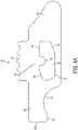
- the liner 22 is shown in FIG. 3 .
- the gap or width of the wing groove 62 is less than when the wing is inserted, demonstrating the tension applied by the force producing member 61 when the wing is inserted.
- the wing groove 62 includes a front tooth 63 and a rear tooth 64, which act as place holders for the wing 51 in the locked and unlocked positions, respectively.
- FIGS. 4A and 4B show the details of the safety switch 50.
- the safety switch 50 includes wings 51 having an indexing cavity 52 and disposed on either side of the central portion 56.
- the central portion 56 further includes a front end 80 and a rear end 81.
- the safety switch 50 includes a thumb actuation surface 57, that, in the assembled knife, protrudes from the knife handle so that a finger or thumb of a user can access the safety switch 50, for example, to slide the safety switch 50 back and forth between the locked to unlocked positions.
- the wing 51 includes several surfaces that are designed to allow the safety switch 50 to slide back and forth as well as rock when the knife blade is moved from the open position to the closed position while the safety switch 50 is in the closed, safety on position.
- the lower sliding surface 53 and the upper sliding surface 54 allow the safety switch 50 to move forward and backward within the wing groove.
- a forward ramped surface 58 and a rear ramped surface 59 are configured to allow the safety switch 50 to pivot within the wing groove and allow the front end 80 of the safety switch 50 to move upward, for example in response to rotation of the blade from the open position to the closed position when the safety switch is in the safety on position. This movement will be discussed in more detail below with respect to FIGS. 5A-5C .
- the front end 80 includes a front scalloped pocket 82, a bumper 83, and a front surface 84. These aspects of the safety switch 50 will be discussed further with respect to FIGS. 5A-5C . As best shown in FIG.
- the bottom of the central portion 57 includes a central channel 85 that separates two side rails 86.
- the central channel 85 and the rails 86 are configured so that the blade of the knife can slot into the central portion 57 when the blade is in the closed position.
- the two side rails 86 further provide a location for the attachment of the wing 51.
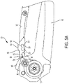
- FIGS. 5A-5B the operation of the safety lock mechanism will be discussed.
- the mechanism is jointly composed of features of the blade 15, the liner 20, and the safety switch 50.
- FIG. 5A is a cross sectional view of the knife shown in FIG. 2 in a partially assembled condition with the blade 15 in a closed position with the safety switch 50 in the safety on, locked position.
- the tang portion 16 of the blade 15 includes several features that work in concert with safety switch 50 to provide a safety lock mechanism that helps to prevent the unwanted assisted deployment of the blade 15.
- the liner 20 provides the force to hold the safety switch 50 in position as well as a channel for its movement.
- the tang portion 16 includes the flipper 90, which is extended from the remainder of the tang and provides a lever for activation of the assist mechanism.
- the flipper 90 includes a scalloped pocket 92 and a protruding portion 93 separated from the sharpened part of the blade 15 by a choil 91.
- the scalloped pocket 92 and the protruding portion 93 provide a stop to accommodate the bumper 83 and the front surface 84 of the safety switch 50.
- the bumper 83 sits in the scalloped pocket 92 and rotation of the blade 15 from the closed position to the open position is prevented by the protruding portion 93 running or bumping against the front surface 84 of the safety switch 50.
- FIG. 5B is a cross sectional view of the knife shown in FIG. 2 in a partially assembled condition with the blade 15 in a partial open position as the blade 15 is being transitioned from the open, extended position to the closed positon with the safety switch 50 in the safety on, locked position.
- the flipper 90 pushes the bumper 82 upward causing the safety switch 50 to rotate about the wing 51.
- FIG. 5C is a cross sectional view of the knife shown in FIG. 2 in a partially assembled condition with the blade 15 in closed position with the safety switch 50 in the off, unlocked position. In this position, it is evident that the bumper 84 is no longer in a position to inhibit the deployment of the blade 15.
- a cylindrical sleeve 44 extends through a bore 40 formed in liner 20, and an aligned bore 42 formed in the liner 22.
- the cylindrical sleeve 44 also extends through aligned pivot bore 46 through tang portion 16 of blade 15.
- the cylindrical sleeve 44 is fitted snugly and fixedly through the pivot bore 46 in tang 16 of blade 15 so that the cylindrical sleeve 44 defines a rotational pivot axis for the blade extending transversely with respect to the plane of the blade 15 and the handle halves 13 and 17.
- sleeve 44 is axially aligned in the Z-direction-transverse to the X-Y plane.
- torsion spring 45 Disposed within the cylindrical sleeve 44 is torsion spring 45.
- sleeve cap 37 fits within a groove of the cylindrical sleeve 44.
- One leg of torsion spring 45 fits within a groove in the cylindrical sleeve 44 while another leg of the torsion spring 45 fits within a recess 47 in the tang portion 16 of the blade 15.
Landscapes
- Engineering & Computer Science (AREA)
- Mechanical Engineering (AREA)
- Life Sciences & Earth Sciences (AREA)
- Forests & Forestry (AREA)
- Knives (AREA)
Claims (14)
- Outil pliant (10) comprenant :une poignée (12) ayant une première moitié de poignée (13) et une deuxième moitié de poignée (17) tenues dans une relation espacée pour former entre elles une rainure d'accessoire ;un accessoire relié pivotant entre la première moitié de poignée (13) et une deuxième moitié de poignée (17) par un pivot (25) et mobile entre une position ouverte et une position fermée, l'accessoire ayant une soie (16) et une partie de fonctionnement (15) ;un mécanisme de verrouillage de sûreté, comprenant :un commutateur de sûreté (50) positionné entre la première moitié de poignée (13) et la deuxième moitié de poignée (17) et ayant une partie centrale (56) avec une extrémité avant (80), une extrémité arrière (81), un côté supérieur, un côté inférieur, et deux portions d'aile (51) s'étendant latéralement depuis la partie centrale (56) mobile d'une première position de sûreté active à une deuxième position de sûreté inactive, les deux portions d'aile (51) configurées pour coulisser à l'intérieur de rainures d'aile (62) de la première moitié de poignée (13) et de la deuxième moitié de poignée (17) ;une protubérance dans la soie 16) qui est configurée pour interagir avec l'extrémité avant (80) du commutateur de sûreté (50) quand le commutateur de sûreté (50) est dans la première position de sûreté active ; etun organe de production de force (61) qui retient le commutateur de sûreté (50),caractérisé en ce que le commutateur de sûreté (50) est configuré pour tourner autour des ailes (51) dans les rainures d'aile (62) quand le commutateur de sûreté (50) est dans la première position de sûreté active alors que l'accessoire est déplacé de la position ouverte à la position fermée, et dans lequel le commutateur de sûreté (50) est configuré pour revenir à la position de sûreté active une fois que l'accessoire est dans la position fermée.
- Outil pliant (10) de la revendication 1, dans lequel le commutateur de sûreté (50) est mobile jusqu'à la première position de sûreté active quand l'accessoire est dans la position ouverte sans empêcher le déplacement de l'accessoire jusqu'à la position fermée.
- Outil pliant (10) de la revendication 1 ou 2, dans lequel les deux ailes (51) incluent chacune une surface de guide supérieure et une surface de guide inférieure et dans lequel les surfaces de guide supérieure et inférieure sont configurées pour coulisser à l'intérieur des rainures d'aile (62).
- Outil pliant (10) selon l'une quelconque des revendications précédentes, dans lequel les deux ailes (51) incluent chacune une surface à rampe avant (58) et une surface à rampe arrière (58) et dans lequel la surface à rampe avant (58) et la surface à rampe arrière (59) sont configurées pour permettre au commutateur de sûreté (50) de tourner autour des ailes (51) dans les rainures d'aile (62) en réponse à une pression vers le haut sur l'extrémité avant (80) du commutateur de sûreté (50).
- Outil pliant (10) selon l'une quelconque des revendications précédentes, dans lequel la soie (16) inclut en outre une poche dentelée (92) adjacente à la protubérance et dans lequel l'extrémité avant (80) du commutateur de sûreté (50) est retenue dans la poche dentelée (92) quand le commutateur de sûreté (50) est dans la première position de sûreté.
- Outil pliant (10) selon l'une quelconque des revendications précédentes, dans lequel les ailes (51) ont une cavité d'indexage (52) et les rainures d'aile (62) ont des dents d'indexage (63, 64) et dans lequel le commutateur de sûreté (50) est positionné dans la position verrouillée ou déverrouillée par les dents d'indexage (63, 64) interagissant avec la cavité d'indexage (52).
- Outil pliant (10) selon l'une quelconque des revendications précédentes, dans lequel la partie centrale (56) du commutateur de sûreté (50) comprend un canal central (85) sur le côté inférieur séparant deux rails latéraux (86), dans lequel le canal central (85) est configuré pour accepter l'extrémité de fonctionnement de la lame (15), dans la position fermée ; optionnellement dans lequel les deux ailes (51) sont couplées aux deux rails latéraux (86).
- Outil pliant (10) selon l'une quelconque des revendications précédentes, dans lequel le commutateur de sûreté (50) comprend une surface d'actionnement par le pouce (57) qui s'étend depuis la poignée (12) de l'outil pliant (10).
- Outil pliant (10) selon l'une quelconque des revendications précédentes, dans lequel la première moitié de poignée (13) et la deuxième moitié de poignée (17) comprennent chacune une paroi latérale (14, 18) et une garniture (20, 22), et dans lequel chaque garniture (20, 22) a l'organe de production de force (61) couplé à celle-ci; optionnellement dans lequel l'organe de production de force (61) et la garniture (20, 22) sont une même pièce de matériau d'un seul tenant.
- Outil pliant (10) selon l'une quelconque des revendications précédentes, dans lequel l'organe de production de force (61) comprend un ressort ; optionnellement dans lequel le ressort comprend un ressort à lame/en porte-à-faux.
- Outil pliant (10) selon l'une quelconque des revendications précédentes, dans lequel l'accessoire comprend une lame de couteau (15).
- Outil pliant (10) selon l'une quelconque des revendications précédentes, dans lequel la soie (16) comprend une bascule (90).
- Outil pliant (10) selon l'une quelconque des revendications précédentes, comprenant en outre un mécanisme d'assistance d'ouverture (30) ; optionnellement dans lequel le mécanisme d'assistance d'ouverture (30) comprend un manchon cylindrique (44) disposé autour du pivot (25) et un ressort de torsion (45) disposé à l'intérieur du manchon cylindrique (44) et autour du pivot (25).
- Outil pliant (10) selon l'une quelconque des revendications précédentes, comprenant en outre une barre de verrouillage (28) qui est mobile entre une première position et une deuxième position, dans lequel la première position verrouille l'accessoire dans une position ouverte, et l'amenée de la barre de verrouillage (28) dans la deuxième position libère l'accessoire du verrouillage dans la position ouverte ; optionnellement dans lequel la barre de verrouillage (28) est contrainte vers la première position par un ou plusieurs ressorts (60) ; et/ou dans lequel la soie (16) comprend une première surface à rampe qui interagit avec la barre de verrouillage (28) dans la position ouverte.
Applications Claiming Priority (1)
| Application Number | Priority Date | Filing Date | Title |
|---|---|---|---|
| US15/844,383 US10899024B2 (en) | 2017-12-15 | 2017-12-15 | Safety for assist opening knife |
Publications (2)
| Publication Number | Publication Date |
|---|---|
| EP3498439A1 EP3498439A1 (fr) | 2019-06-19 |
| EP3498439B1 true EP3498439B1 (fr) | 2022-06-29 |
Family
ID=64665549
Family Applications (1)
| Application Number | Title | Priority Date | Filing Date |
|---|---|---|---|
| EP18212561.7A Active EP3498439B1 (fr) | 2017-12-15 | 2018-12-14 | Sécurité pour assister un couteau d'ouverture |
Country Status (4)
| Country | Link |
|---|---|
| US (1) | US10899024B2 (fr) |
| EP (1) | EP3498439B1 (fr) |
| CN (1) | CN109968405B (fr) |
| TW (1) | TWI693991B (fr) |
Families Citing this family (6)
| Publication number | Priority date | Publication date | Assignee | Title |
|---|---|---|---|---|
| US11135730B1 (en) * | 2018-01-24 | 2021-10-05 | Rexford Knives, LLC | Switch lock apparatus |
| US11298837B2 (en) * | 2019-03-11 | 2022-04-12 | Milwaukee Electric Tool Corporation | Folding knife safety mechanism |
| US11904484B2 (en) * | 2020-08-24 | 2024-02-20 | Benchmade Knife Co., Inc. | Knife with specialized balance and blade length |
| CN118488887A (zh) | 2021-10-22 | 2024-08-13 | 菲斯科尔思品牌有限公司 | 具有安全锁的刀 |
| US12552054B2 (en) * | 2023-10-03 | 2026-02-17 | Kai U.S.A., Ltd. | Assisted opening and closing knife with lock |
| US12600046B2 (en) * | 2024-04-01 | 2026-04-14 | Andrew Demko | Auto opening folding knife blade engagement lock |
Family Cites Families (28)
| Publication number | Priority date | Publication date | Assignee | Title |
|---|---|---|---|---|
| US4535539A (en) | 1984-03-13 | 1985-08-20 | Jet Aer Corporation | Folding knife with safety locking feature |
| US5596808A (en) | 1995-06-28 | 1997-01-28 | Lake; Ronald W. | Safety for knife-blade lock |
| US5737841A (en) | 1996-07-12 | 1998-04-14 | Mchenry; William J. | Pocket knife with lock |
| US5822866A (en) | 1997-01-17 | 1998-10-20 | Mentor Group, L.L.C. | Safety lock for automatic knife |
| US5964036A (en) | 1997-11-12 | 1999-10-12 | Spyderco, Inc. | Folding knife with secondary locking mechanism |
| US6591504B2 (en) | 2001-07-12 | 2003-07-15 | Kat U.S.A. Ltd. | Folding knife with safety lock |
| US6675484B2 (en) | 2001-07-30 | 2004-01-13 | Mentor Group Llc | Folding tool locking mechanism |
| US7032315B1 (en) | 2002-05-31 | 2006-04-25 | Busse Jerry P | Folding knife with locking blade |
| US7062857B1 (en) * | 2002-10-23 | 2006-06-20 | Taylor Cutlery Llc | Knife with blade lock and lanyard lock |
| US20040158991A1 (en) | 2003-02-13 | 2004-08-19 | Alterra Holdings Corporation | Safety for a folding knife |
| US7140110B2 (en) | 2003-06-04 | 2006-11-28 | Lake Ronald W | Folding knife having a locking mechanism |
| US7596870B2 (en) | 2004-03-02 | 2009-10-06 | Leatherman Tool Group, Inc. | Folding multipurpose tool with shears and comfortable handles |
| US7437822B2 (en) | 2005-05-18 | 2008-10-21 | Gbii Corporation | Locking mechanism for folding knife |
| US7305768B2 (en) | 2005-08-18 | 2007-12-11 | Mentor Group, Llc | Locking mechanism for folding tool |
| US7698821B2 (en) | 2006-01-20 | 2010-04-20 | Darrel Ralph | Lock mechanism for spring assisted folding knife |
| US20070169351A1 (en) | 2006-01-25 | 2007-07-26 | Mentor Group Llc | Folding tool with lockback mechanism |
| US7748122B2 (en) | 2007-09-05 | 2010-07-06 | Mentor Group, L.L.C. | Knife blade opening mechanism |
| US7941927B1 (en) | 2007-12-10 | 2011-05-17 | Cold Steel | Folding knife lock |
| US20090165308A1 (en) | 2007-12-27 | 2009-07-02 | Iron Bridge Tools (Ibt) Holding, Llc | Utility knife with folding mechanism |
| US7979990B2 (en) | 2008-05-21 | 2011-07-19 | Kai U.S.A., Ltd. | Safety lock mechanism for folding knives |
| US20100192381A1 (en) | 2009-02-02 | 2010-08-05 | Gerber Sakai Co., Ltd. | Folding knife with blade open assisting function |
| US8413338B2 (en) * | 2009-07-14 | 2013-04-09 | Fiskars Brands, Inc. | Folding knife with safety and wedge lock |
| WO2014130905A2 (fr) | 2013-02-25 | 2014-08-28 | Mentor Group, L.L.C. | Couteau à actionneurs ambidextres et mécanisme de verrouillage |
| CN203510249U (zh) | 2013-11-04 | 2014-04-02 | 蒋明基 | 一种刀头角度可调节的折叠刀 |
| US9737997B1 (en) | 2014-05-30 | 2017-08-22 | Marfione Custom Knives, LLC | Rotatable safety mechanism for automatic folding knife |
| US9259845B2 (en) | 2014-06-17 | 2016-02-16 | Allway Tools, Inc. | Carpet cutter assembly |
| US9943970B2 (en) | 2014-11-14 | 2018-04-17 | Spyderco, Inc. | Rotational wedge locking mechanism for a folding knife |
| US9908245B1 (en) * | 2016-11-03 | 2018-03-06 | Sport Manufacturing Group Inc. | Locking mechanism for a folding instrument |
-
2017
- 2017-12-15 US US15/844,383 patent/US10899024B2/en active Active
-
2018
- 2018-12-06 TW TW107143911A patent/TWI693991B/zh active
- 2018-12-14 EP EP18212561.7A patent/EP3498439B1/fr active Active
- 2018-12-14 CN CN201811536335.XA patent/CN109968405B/zh active Active
Also Published As
| Publication number | Publication date |
|---|---|
| CN109968405B (zh) | 2021-03-12 |
| TWI693991B (zh) | 2020-05-21 |
| EP3498439A1 (fr) | 2019-06-19 |
| US20190184584A1 (en) | 2019-06-20 |
| TW201927499A (zh) | 2019-07-16 |
| US10899024B2 (en) | 2021-01-26 |
| CN109968405A (zh) | 2019-07-05 |
Similar Documents
| Publication | Publication Date | Title |
|---|---|---|
| EP3498439B1 (fr) | Sécurité pour assister un couteau d'ouverture | |
| EP3672766B1 (fr) | Mécanisme de verrouillage à double lame | |
| CN111185939B (zh) | 直出式刀具 | |
| EP2958713B1 (fr) | Couteau pliant présentant deux modes de fonctionnement | |
| EP2892695B1 (fr) | Couteau pliant ayant deux modes de fonctionnement | |
| US8671578B1 (en) | Forward extending assisted opening knife | |
| EP1885526B1 (fr) | Mecanisme d'ouverture de lame de couteau | |
| US8286357B2 (en) | Locking mechanism for a folding knife | |
| TW202214405A (zh) | 具有特殊平衡和刀片長度的刀具 | |
| US7941927B1 (en) | Folding knife lock | |
| US8402663B2 (en) | Two-piece hand tool | |
| US10820628B2 (en) | Cigar cutter | |
| US20120017441A1 (en) | Combination dual blade knife | |
| US20250303592A1 (en) | Auto opening folding knife blade engagement lock | |
| US20070157472A1 (en) | Utility knife with releasable blade retention mechanism | |
| CN222328266U (zh) | 折叠刀 | |
| HK40009691A (en) | Safety device for assist opening knife | |
| CZ307281B6 (cs) | Nůž s výsuvnou čepelí | |
| HK40009691B (zh) | 用於辅助打开式刀具的安全装置 | |
| HK40028397A (en) | Out the front knife | |
| HK40028397B (en) | Out the front knife | |
| US20260091522A1 (en) | Folding knife blade engagement lock | |
| HK40029062A (zh) | 双刀片锁定机构 | |
| HK40029062B (en) | Dual blade locking mechanism | |
| WO2017135964A1 (fr) | Couteau universel pliant avec verrou automatique |
Legal Events
| Date | Code | Title | Description |
|---|---|---|---|
| PUAI | Public reference made under article 153(3) epc to a published international application that has entered the european phase |
Free format text: ORIGINAL CODE: 0009012 |
|
| STAA | Information on the status of an ep patent application or granted ep patent |
Free format text: STATUS: REQUEST FOR EXAMINATION WAS MADE |
|
| 17P | Request for examination filed |
Effective date: 20181220 |
|
| AK | Designated contracting states |
Kind code of ref document: A1 Designated state(s): AL AT BE BG CH CY CZ DE DK EE ES FI FR GB GR HR HU IE IS IT LI LT LU LV MC MK MT NL NO PL PT RO RS SE SI SK SM TR |
|
| AX | Request for extension of the european patent |
Extension state: BA ME |
|
| GRAP | Despatch of communication of intention to grant a patent |
Free format text: ORIGINAL CODE: EPIDOSNIGR1 |
|
| STAA | Information on the status of an ep patent application or granted ep patent |
Free format text: STATUS: GRANT OF PATENT IS INTENDED |
|
| INTG | Intention to grant announced |
Effective date: 20220125 |
|
| GRAS | Grant fee paid |
Free format text: ORIGINAL CODE: EPIDOSNIGR3 |
|
| GRAA | (expected) grant |
Free format text: ORIGINAL CODE: 0009210 |
|
| STAA | Information on the status of an ep patent application or granted ep patent |
Free format text: STATUS: THE PATENT HAS BEEN GRANTED |
|
| AK | Designated contracting states |
Kind code of ref document: B1 Designated state(s): AL AT BE BG CH CY CZ DE DK EE ES FI FR GB GR HR HU IE IS IT LI LT LU LV MC MK MT NL NO PL PT RO RS SE SI SK SM TR |
|
| REG | Reference to a national code |
Ref country code: CH Ref legal event code: EP |
|
| REG | Reference to a national code |
Ref country code: AT Ref legal event code: REF Ref document number: 1501013 Country of ref document: AT Kind code of ref document: T Effective date: 20220715 |
|
| REG | Reference to a national code |
Ref country code: IE Ref legal event code: FG4D |
|
| REG | Reference to a national code |
Ref country code: DE Ref legal event code: R096 Ref document number: 602018037255 Country of ref document: DE |
|
| REG | Reference to a national code |
Ref country code: LT Ref legal event code: MG9D |
|
| PG25 | Lapsed in a contracting state [announced via postgrant information from national office to epo] |
Ref country code: SE Free format text: LAPSE BECAUSE OF FAILURE TO SUBMIT A TRANSLATION OF THE DESCRIPTION OR TO PAY THE FEE WITHIN THE PRESCRIBED TIME-LIMIT Effective date: 20220629 Ref country code: NO Free format text: LAPSE BECAUSE OF FAILURE TO SUBMIT A TRANSLATION OF THE DESCRIPTION OR TO PAY THE FEE WITHIN THE PRESCRIBED TIME-LIMIT Effective date: 20220929 Ref country code: LT Free format text: LAPSE BECAUSE OF FAILURE TO SUBMIT A TRANSLATION OF THE DESCRIPTION OR TO PAY THE FEE WITHIN THE PRESCRIBED TIME-LIMIT Effective date: 20220629 Ref country code: HR Free format text: LAPSE BECAUSE OF FAILURE TO SUBMIT A TRANSLATION OF THE DESCRIPTION OR TO PAY THE FEE WITHIN THE PRESCRIBED TIME-LIMIT Effective date: 20220629 Ref country code: GR Free format text: LAPSE BECAUSE OF FAILURE TO SUBMIT A TRANSLATION OF THE DESCRIPTION OR TO PAY THE FEE WITHIN THE PRESCRIBED TIME-LIMIT Effective date: 20220930 Ref country code: FI Free format text: LAPSE BECAUSE OF FAILURE TO SUBMIT A TRANSLATION OF THE DESCRIPTION OR TO PAY THE FEE WITHIN THE PRESCRIBED TIME-LIMIT Effective date: 20220629 Ref country code: BG Free format text: LAPSE BECAUSE OF FAILURE TO SUBMIT A TRANSLATION OF THE DESCRIPTION OR TO PAY THE FEE WITHIN THE PRESCRIBED TIME-LIMIT Effective date: 20220929 |
|
| REG | Reference to a national code |
Ref country code: NL Ref legal event code: MP Effective date: 20220629 |
|
| REG | Reference to a national code |
Ref country code: AT Ref legal event code: MK05 Ref document number: 1501013 Country of ref document: AT Kind code of ref document: T Effective date: 20220629 |
|
| PG25 | Lapsed in a contracting state [announced via postgrant information from national office to epo] |
Ref country code: RS Free format text: LAPSE BECAUSE OF FAILURE TO SUBMIT A TRANSLATION OF THE DESCRIPTION OR TO PAY THE FEE WITHIN THE PRESCRIBED TIME-LIMIT Effective date: 20220629 Ref country code: LV Free format text: LAPSE BECAUSE OF FAILURE TO SUBMIT A TRANSLATION OF THE DESCRIPTION OR TO PAY THE FEE WITHIN THE PRESCRIBED TIME-LIMIT Effective date: 20220629 |
|
| PG25 | Lapsed in a contracting state [announced via postgrant information from national office to epo] |
Ref country code: NL Free format text: LAPSE BECAUSE OF FAILURE TO SUBMIT A TRANSLATION OF THE DESCRIPTION OR TO PAY THE FEE WITHIN THE PRESCRIBED TIME-LIMIT Effective date: 20220629 |
|
| PG25 | Lapsed in a contracting state [announced via postgrant information from national office to epo] |
Ref country code: SM Free format text: LAPSE BECAUSE OF FAILURE TO SUBMIT A TRANSLATION OF THE DESCRIPTION OR TO PAY THE FEE WITHIN THE PRESCRIBED TIME-LIMIT Effective date: 20220629 Ref country code: SK Free format text: LAPSE BECAUSE OF FAILURE TO SUBMIT A TRANSLATION OF THE DESCRIPTION OR TO PAY THE FEE WITHIN THE PRESCRIBED TIME-LIMIT Effective date: 20220629 Ref country code: RO Free format text: LAPSE BECAUSE OF FAILURE TO SUBMIT A TRANSLATION OF THE DESCRIPTION OR TO PAY THE FEE WITHIN THE PRESCRIBED TIME-LIMIT Effective date: 20220629 Ref country code: PT Free format text: LAPSE BECAUSE OF FAILURE TO SUBMIT A TRANSLATION OF THE DESCRIPTION OR TO PAY THE FEE WITHIN THE PRESCRIBED TIME-LIMIT Effective date: 20221031 Ref country code: ES Free format text: LAPSE BECAUSE OF FAILURE TO SUBMIT A TRANSLATION OF THE DESCRIPTION OR TO PAY THE FEE WITHIN THE PRESCRIBED TIME-LIMIT Effective date: 20220629 Ref country code: EE Free format text: LAPSE BECAUSE OF FAILURE TO SUBMIT A TRANSLATION OF THE DESCRIPTION OR TO PAY THE FEE WITHIN THE PRESCRIBED TIME-LIMIT Effective date: 20220629 Ref country code: AT Free format text: LAPSE BECAUSE OF FAILURE TO SUBMIT A TRANSLATION OF THE DESCRIPTION OR TO PAY THE FEE WITHIN THE PRESCRIBED TIME-LIMIT Effective date: 20220629 |
|
| PG25 | Lapsed in a contracting state [announced via postgrant information from national office to epo] |
Ref country code: PL Free format text: LAPSE BECAUSE OF FAILURE TO SUBMIT A TRANSLATION OF THE DESCRIPTION OR TO PAY THE FEE WITHIN THE PRESCRIBED TIME-LIMIT Effective date: 20220629 Ref country code: IS Free format text: LAPSE BECAUSE OF FAILURE TO SUBMIT A TRANSLATION OF THE DESCRIPTION OR TO PAY THE FEE WITHIN THE PRESCRIBED TIME-LIMIT Effective date: 20221029 |
|
| REG | Reference to a national code |
Ref country code: DE Ref legal event code: R097 Ref document number: 602018037255 Country of ref document: DE |
|
| PG25 | Lapsed in a contracting state [announced via postgrant information from national office to epo] |
Ref country code: AL Free format text: LAPSE BECAUSE OF FAILURE TO SUBMIT A TRANSLATION OF THE DESCRIPTION OR TO PAY THE FEE WITHIN THE PRESCRIBED TIME-LIMIT Effective date: 20220629 |
|
| PG25 | Lapsed in a contracting state [announced via postgrant information from national office to epo] |
Ref country code: DK Free format text: LAPSE BECAUSE OF FAILURE TO SUBMIT A TRANSLATION OF THE DESCRIPTION OR TO PAY THE FEE WITHIN THE PRESCRIBED TIME-LIMIT Effective date: 20220629 Ref country code: CZ Free format text: LAPSE BECAUSE OF FAILURE TO SUBMIT A TRANSLATION OF THE DESCRIPTION OR TO PAY THE FEE WITHIN THE PRESCRIBED TIME-LIMIT Effective date: 20220629 |
|
| PLBE | No opposition filed within time limit |
Free format text: ORIGINAL CODE: 0009261 |
|
| STAA | Information on the status of an ep patent application or granted ep patent |
Free format text: STATUS: NO OPPOSITION FILED WITHIN TIME LIMIT |
|
| 26N | No opposition filed |
Effective date: 20230330 |
|
| P01 | Opt-out of the competence of the unified patent court (upc) registered |
Effective date: 20230518 |
|
| REG | Reference to a national code |
Ref country code: CH Ref legal event code: PL |
|
| GBPC | Gb: european patent ceased through non-payment of renewal fee |
Effective date: 20221214 |
|
| REG | Reference to a national code |
Ref country code: BE Ref legal event code: MM Effective date: 20221231 |
|
| PG25 | Lapsed in a contracting state [announced via postgrant information from national office to epo] |
Ref country code: SI Free format text: LAPSE BECAUSE OF FAILURE TO SUBMIT A TRANSLATION OF THE DESCRIPTION OR TO PAY THE FEE WITHIN THE PRESCRIBED TIME-LIMIT Effective date: 20220629 Ref country code: LU Free format text: LAPSE BECAUSE OF NON-PAYMENT OF DUE FEES Effective date: 20221214 |
|
| PG25 | Lapsed in a contracting state [announced via postgrant information from national office to epo] |
Ref country code: LI Free format text: LAPSE BECAUSE OF NON-PAYMENT OF DUE FEES Effective date: 20221231 Ref country code: IE Free format text: LAPSE BECAUSE OF NON-PAYMENT OF DUE FEES Effective date: 20221214 Ref country code: GB Free format text: LAPSE BECAUSE OF NON-PAYMENT OF DUE FEES Effective date: 20221214 Ref country code: CH Free format text: LAPSE BECAUSE OF NON-PAYMENT OF DUE FEES Effective date: 20221231 |
|
| PG25 | Lapsed in a contracting state [announced via postgrant information from national office to epo] |
Ref country code: BE Free format text: LAPSE BECAUSE OF NON-PAYMENT OF DUE FEES Effective date: 20221231 |
|
| PG25 | Lapsed in a contracting state [announced via postgrant information from national office to epo] |
Ref country code: HU Free format text: LAPSE BECAUSE OF FAILURE TO SUBMIT A TRANSLATION OF THE DESCRIPTION OR TO PAY THE FEE WITHIN THE PRESCRIBED TIME-LIMIT; INVALID AB INITIO Effective date: 20181214 |
|
| PG25 | Lapsed in a contracting state [announced via postgrant information from national office to epo] |
Ref country code: CY Free format text: LAPSE BECAUSE OF FAILURE TO SUBMIT A TRANSLATION OF THE DESCRIPTION OR TO PAY THE FEE WITHIN THE PRESCRIBED TIME-LIMIT Effective date: 20220629 |
|
| PG25 | Lapsed in a contracting state [announced via postgrant information from national office to epo] |
Ref country code: MK Free format text: LAPSE BECAUSE OF FAILURE TO SUBMIT A TRANSLATION OF THE DESCRIPTION OR TO PAY THE FEE WITHIN THE PRESCRIBED TIME-LIMIT Effective date: 20220629 |
|
| PG25 | Lapsed in a contracting state [announced via postgrant information from national office to epo] |
Ref country code: MC Free format text: LAPSE BECAUSE OF FAILURE TO SUBMIT A TRANSLATION OF THE DESCRIPTION OR TO PAY THE FEE WITHIN THE PRESCRIBED TIME-LIMIT Effective date: 20220629 |
|
| PG25 | Lapsed in a contracting state [announced via postgrant information from national office to epo] |
Ref country code: TR Free format text: LAPSE BECAUSE OF FAILURE TO SUBMIT A TRANSLATION OF THE DESCRIPTION OR TO PAY THE FEE WITHIN THE PRESCRIBED TIME-LIMIT Effective date: 20220629 Ref country code: MC Free format text: LAPSE BECAUSE OF FAILURE TO SUBMIT A TRANSLATION OF THE DESCRIPTION OR TO PAY THE FEE WITHIN THE PRESCRIBED TIME-LIMIT Effective date: 20220629 |
|
| PG25 | Lapsed in a contracting state [announced via postgrant information from national office to epo] |
Ref country code: MT Free format text: LAPSE BECAUSE OF FAILURE TO SUBMIT A TRANSLATION OF THE DESCRIPTION OR TO PAY THE FEE WITHIN THE PRESCRIBED TIME-LIMIT Effective date: 20220629 |
|
| PG25 | Lapsed in a contracting state [announced via postgrant information from national office to epo] |
Ref country code: BG Free format text: LAPSE BECAUSE OF FAILURE TO SUBMIT A TRANSLATION OF THE DESCRIPTION OR TO PAY THE FEE WITHIN THE PRESCRIBED TIME-LIMIT Effective date: 20220629 |
|
| PG25 | Lapsed in a contracting state [announced via postgrant information from national office to epo] |
Ref country code: BG Free format text: LAPSE BECAUSE OF FAILURE TO SUBMIT A TRANSLATION OF THE DESCRIPTION OR TO PAY THE FEE WITHIN THE PRESCRIBED TIME-LIMIT Effective date: 20220629 |
|
| PGFP | Annual fee paid to national office [announced via postgrant information from national office to epo] |
Ref country code: IT Payment date: 20251219 Year of fee payment: 8 |
|
| PGFP | Annual fee paid to national office [announced via postgrant information from national office to epo] |
Ref country code: FR Payment date: 20251226 Year of fee payment: 8 |
|
| PGFP | Annual fee paid to national office [announced via postgrant information from national office to epo] |
Ref country code: DE Payment date: 20251229 Year of fee payment: 8 |