EP3513765A1 - Werkstückspannvorrichtung - Google Patents
Werkstückspannvorrichtung Download PDFInfo
- Publication number
- EP3513765A1 EP3513765A1 EP19152978.3A EP19152978A EP3513765A1 EP 3513765 A1 EP3513765 A1 EP 3513765A1 EP 19152978 A EP19152978 A EP 19152978A EP 3513765 A1 EP3513765 A1 EP 3513765A1
- Authority
- EP
- European Patent Office
- Prior art keywords
- workpiece
- support unit
- diameter portion
- clamping device
- opening
- Prior art date
- Legal status (The legal status is an assumption and is not a legal conclusion. Google has not performed a legal analysis and makes no representation as to the accuracy of the status listed.)
- Withdrawn
Links
- 238000003801 milling Methods 0.000 description 19
- 125000006850 spacer group Chemical group 0.000 description 6
- 238000000227 grinding Methods 0.000 description 3
- 238000004519 manufacturing process Methods 0.000 description 3
- 238000000034 method Methods 0.000 description 3
- 238000000465 moulding Methods 0.000 description 2
- 239000011347 resin Substances 0.000 description 2
- 229920005989 resin Polymers 0.000 description 2
- 238000005520 cutting process Methods 0.000 description 1
- 235000012489 doughnuts Nutrition 0.000 description 1
- 238000005516 engineering process Methods 0.000 description 1
- 238000003754 machining Methods 0.000 description 1
- 239000011505 plaster Substances 0.000 description 1
Images


Classifications
-
- A—HUMAN NECESSITIES
- A61—MEDICAL OR VETERINARY SCIENCE; HYGIENE
- A61C—DENTISTRY; APPARATUS OR METHODS FOR ORAL OR DENTAL HYGIENE
- A61C13/00—Dental prostheses; Making same
- A61C13/0003—Making bridge-work, inlays, implants or the like
- A61C13/0022—Blanks or green, unfinished dental restoration parts
Definitions
- the present invention relates to a workpiece clamping device attached to or mounted in a milling machine and configured to hold a workpiece to be machined (processed) to a prosthesis.
- a milling machine is known as a machine to grind a workpiece to a prosthesis such as an artificial tooth (dental prosthesis).
- a prosthesis such as an artificial tooth (dental prosthesis).
- One of conventional technologies relevant to the milling machines is disclosed in Japanese Patent Application Laid-Open Publication No. 2017-189340 .
- the milling machine such as the one disclosed in Japanese Patent Application Laid-Open Publication No. 2017-189340 , has a workpiece clamping device to hold a workpiece which will be processed to the prosthesis.
- the workpiece clamping device is disposed such that it can rotate.
- the milling machine processes the workpiece to a desired shape with a tool such as a drill, while causing the workpiece to rotate.
- the prosthesis obtained by the processing of the milling machine may be artificial teeth, a combination of the artificial teeth and a dental plate (denture base), or the like. Different kinds of workpiece are used depending upon the kinds of the prosthesis to be obtained.
- the prosthesis to be obtained is a combination of the artificial teeth and the dental plate (the dental plate is integrated with the artificial teeth)
- the workpiece should have a larger size than when the prosthesis to be obtained is artificial teeth alone. It is desirable if a single clamping device can hold different sizes of workpieces.
- One object of the present invention is to provide a workpiece clamping device that can hold workpieces having different sizes.
- a workpiece clamping device configured to be able to support a first workpiece and a second workpiece, the first workpiece having a first large-diameter portion that is generally shaped like a disc, the first large-diameter portion defining a largest outer diameter portion of the first workpiece, the first workpiece being ground to a first prosthesis, the second workpiece having a second large-diameter portion whose outer diameter is greater than the first large-diameter portion, the second large-diameter portion defining a largest outer diameter portion of the second workpiece, the second workpiece being ground to a second prosthesis, which is different from the first prosthesis, the workpiece clamping device including: a support unit configured to support the second large-diameter portion on an upper face of the support unit, the support unit having an opening through which the first workpiece and the second workpiece can move, the support unit also having protruding portions extending toward a center of the opening of the support unit from certain portions
- the support unit can support (hold) the second large-diameter portion on the upper face of the support unit, and support the first large-diameter portion on the protruding portions of the support unit, which extend toward the center of the opening of the support unit.
- the two kinds of workpieces having different sizes, can be placed on the upper face and the protruding portions of the support unit, respectively. It is not necessary to prepare different support units and clamping plates depending upon the kinds of the workpieces. Rather, the single workpiece clamping device can hold the different sizes of workpieces.
- Fr indicates front
- Rr indicates rear
- Le indicates left
- Ri indicates right
- Up indicates up
- Dn indicates down
- Ce indicates the center of a workpiece clamping device.
- a milling machine 10 is used to obtain a dental prosthesis by machining or processing.
- the milling machine 10 includes a rotating device 13 configured to rotatably support a first workpiece 50, a workpiece clamping device 30 fixed to the rotating device 13 and configured to hold the first workpiece 50, and a drill 15 that faces the first workpiece 50 and configured to grind the first workpiece 50.
- the rotating device 13, the workpiece clamping device 30 and the drill 15 are disposed in a milling machine main body 11, which serves as a housing of the milling machine.
- the milling machine main body 11 has a milling machine lid 11a mounted thereon such that the milling machine lid 11a can slide up and down.
- the milling machine lid 11a is lowered to prevent shavings (cuttings) from flying to the outside.
- the rotating device 13 is mounted in the milling machine main body 11 such that the rotating device 13 can rotate, and the rotating device 13 supports the workpiece clamping device 30 such that the workpiece clamping device 30 can rotate.
- the workpiece clamping device 30 includes a support unit 40 on which the first workpiece 50 is placed, a planar clamping plate 32 configured to sandwich the first workpiece 50 between the support unit 40 and the claim plate 32, and tightening members 33 configured to tighten the support unit 40 and the clamping plate 32.
- the Support Unit 40 The Support Unit 40
- the support unit 40 has a generally circular opening 40a in its center area.
- the support unit 40 is constituted by a stack of four plate members (metallic plates) 41-44.
- the four plate members 41-44 are referred to as the first plate member 41, the second plate member 42, the third plate member 43, and the fourth plate member 44 from the bottom of the stack.
- Each of the first plate member 41 to the fourth plate member 44 is prepared by press forming or molding.
- a first opening 41a is formed in a center area of the first plate member 41, and serves as part of the opening 40a of the support unit 40.
- the first opening 41a is smaller than a second opening 42a, a third opening 43a and a fourth opening 44a formed in the center areas of the other plate members 42, 43 and 44, which also serve as parts of the opening 40a of the support unit 40.
- the first plate member 41 more protrudes toward the center than the second plate member 42 to the fourth plate member 44.
- the protruding portion may be referred to as protruding portions 40b of the support unit that extend toward the center of the opening 40a of the support unit 40 from certain portions of the opening 40a and can support the first workpiece 50 thereon.
- the protruding portions 40b of the support unit 40 are formed intermittently on the first plate member 41.
- the clamping plate 32 is a metallic plate that has a generally donut shape.
- the clamping plate 32 has contacting portions 32a along its outer periphery such that each of the contacting portions 32a can contact the shaft of the corresponding tightening member 33.
- the contacting portions 32a extend generally tangentially from the outer periphery of the clamping plate 32, with the angle between each of the contacting portions 32a and the outer periphery being the same.
- the first workpiece 50 is a disk-like plaster. It is possible to obtain a plurality of artificial teeth T1 (prosthesis) from the first workpiece 50 by grinding.
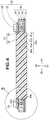
- the first workpiece 50 has a first large-diameter portion 51, which is shaped like a disc and defines the largest outer diameter portion of the first workpiece.
- the first workpiece 50 also has first small-diameter portions 52, each of which is shaped like a disc with an outer diameter smaller than the first large-diameter portion 51.
- the first small-diameter portions 52 are present on and below the first large-diameter portion 51, and the first small-diameter portions 52 are integrated with the first large-diameter portion 51.
- the first workpiece 50 is firstly brought to the opening 40a of the support unit 40.
- the outer diameter of the first large-diameter portion 51 is greater than the inner diameter of the protruding portions 40b of the support unit 40, and the outer diameter of the first small-diameter portion 52 is smaller than the inner diameter of the protruding portions 40b of the support unit.
- the inner diameter of the clamping plate 32 is greater than the outer diameter of each of the first small-diameter portions 52, and smaller than the outer diameter of the first large-diameter portion 51. Thus, it is possible to place the clamping plate 32 on the first large-diameter portion 51.
- the first workpiece 50 is clamped by the workpiece clamping device 30 upon tightening the tightening members 33.
- the workpiece clamping device 30 that has clamped the first workpiece 50 is fixed on the rotating device 13.
- the first workpiece 50 is ground by the drill 15 while causing the first workpiece 50 to rotate, thereby manufacturing the artificial teeth.
- the workpiece clamping device 30 can also clamp different sizes of workpieces other than the first workpiece 50. This will be described below.
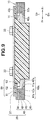
- a second workpiece 60 is made from resin, and ground to false teeth (prosthesis) by the milling machine 10 (see Fig. 1 ). More specifically, the second workpiece 60 is a resin workpiece that has a set of standing artificial teeth T2. The periphery of the artificial teeth T2 is ground in conformity with the gums of a patient to obtain a dental plate (denture base) G.
- the second workpiece 60 has a second large-diameter portion 61, which is shaped like a dis and defines the largest outer diameter of the second workpiece.
- the second workpiece 60 also has a positioning portion 62 integral with the second large-diameter portion 61 and used for positioning, and a main portion 63 integral with the positioning portion 61.
- the prosthesis is obtained by grinding the main portion 63.
- the outer diameter of the second large-diameter portion 61 is greater than the outer diameter of the first large-diameter portion 51.
- the positioning portion 62 has four cut-outs or depressions 62a for positioning, each of which has a depth toward the center.
- the second workpiece 60 is fixed to the workpiece clamping device 30 with a spacer 70.
- the spacer 70 is a component made from a metallic plate.
- the space 70 has projecting portions 71 for positioning, which are fitted in (or are engaged with) the depressions 62a.
- the space 70 also has through holes 72 such that the shaft portions of the tightening members 33 penetrate through the through holes 72.
- Each of the through holes 72 has a larger diameter than the outer diameter of the shaft portion of the tightening member 33.
- the space 70 may not be used if the length of the second workpiece 60 in the axial direction is small or if the fourth plate member 44 has projecting portions for positioning.
- the outer diameter of the second large-diameter portion 61 is greater than the inner diameter of each of the first opening 41a to the fourth opening 44a (greater than the inner diameter of the opening 40a of the support unit 40).
- the second large-diameter portion 61 is placed on the upper surface 40c of the support unit 40 via the spacer 70.
- the space 70 is placed on the top of the support unit 40, and then the second workpiece 60 is placed on the support unit 40.
- the clamping plate 32 is placed over the second workpiece.
- the second workpiece 60 is clamped by the workpiece clamping device 30.
- the support unit 40 can support the second large-diameter portion 61 on its upper face 40c, and support the first large-diameter portion 51 on its protruding portions 40b that extend toward the center of the opening 40a of the support unit 40.
- the two kinds of workpieces 50 and 60 having different sizes, can be placed on the upper face 40c and the protruding portions 40b of the support unit 40, respectively. It is not necessary to prepare different support units 40 and clamping plates 32 depending upon the kinds of the workpieces 50 and 60. Rather, the single workpiece clamping device 30 can hold the different sizes of workpieces 50 and 60.
- the support unit 40 is formed of a stack of plate members 41-44, and the plate member 41 among the plate members 41-44 has the protruding portions 40b. It is possible to manufacture the support unit 40 in a short time because the support unit 40 is made by stacking the plate members 41-44 having different shapes.
- each of the plate members 41-44 is prepared by press forming or molding.
- the plate members 41-44, which are obtained by the press forming process, are piled up so that the support 40 is easy to manufacture, as compared to when grinding a cast product to obtain the support unit.
- first workpiece is processed to a plurality of artificial teeth and the second workpiece is processed to a combination of the artificial teeth and the dental plate (the artificial teeth are integral with the dental plate) in the foregoing description
- first and second workpieces are not limited to such teeth as long as the first and second workpieces have different sizes from each other.
- the present invention is not limited to the above-described embodiments as long as the advantages of the present invention can be obtained.
- the workpiece clamping device of the present invention is suitable for fixing a workpiece that will be processed to a dental prosthesis.
Landscapes
- Health & Medical Sciences (AREA)
- Oral & Maxillofacial Surgery (AREA)
- Dentistry (AREA)
- Epidemiology (AREA)
- Life Sciences & Earth Sciences (AREA)
- Animal Behavior & Ethology (AREA)
- General Health & Medical Sciences (AREA)
- Public Health (AREA)
- Veterinary Medicine (AREA)
- Jigs For Machine Tools (AREA)
Applications Claiming Priority (1)
| Application Number | Priority Date | Filing Date | Title |
|---|---|---|---|
| JP2018008751A JP2019126456A (ja) | 2018-01-23 | 2018-01-23 | ワーククランプ装置 |
Publications (1)
| Publication Number | Publication Date |
|---|---|
| EP3513765A1 true EP3513765A1 (de) | 2019-07-24 |
Family
ID=65199354
Family Applications (1)
| Application Number | Title | Priority Date | Filing Date |
|---|---|---|---|
| EP19152978.3A Withdrawn EP3513765A1 (de) | 2018-01-23 | 2019-01-22 | Werkstückspannvorrichtung |
Country Status (2)
| Country | Link |
|---|---|
| EP (1) | EP3513765A1 (de) |
| JP (1) | JP2019126456A (de) |
Cited By (3)
| Publication number | Priority date | Publication date | Assignee | Title |
|---|---|---|---|---|
| WO2021084141A1 (es) * | 2019-10-30 | 2021-05-06 | Promedent Cad-Cam, S.L.U. | Procedimiento híbrido de fabricación por sinterizado y fresado de conexiones dentales |
| US20220192802A1 (en) * | 2019-09-12 | 2022-06-23 | Heinrich Steger | Retaining device for a dental workpiece |
| CN115582914A (zh) * | 2022-10-12 | 2023-01-10 | 杭州牙科医院集团有限公司 | 一种氧化锆切削设备 |
Families Citing this family (1)
| Publication number | Priority date | Publication date | Assignee | Title |
|---|---|---|---|---|
| JP7194537B2 (ja) * | 2018-09-04 | 2022-12-22 | キヤノン電子株式会社 | 反転ユニットおよび加工装置 |
Citations (4)
| Publication number | Priority date | Publication date | Assignee | Title |
|---|---|---|---|---|
| WO2007003355A1 (de) * | 2005-06-30 | 2007-01-11 | Steger, Heinrich | Trägerplatte für eine kopierfräseinrichtung |
| DE202010001125U1 (de) * | 2010-01-22 | 2010-04-08 | Heimatec Gmbh | Vorrichtung zum Halten von zur Herstellung von Zahnersatzteilen dienenden Rohlingen |
| WO2013117540A1 (de) * | 2012-02-06 | 2013-08-15 | Wieland Dental + Technik Gmbh & Co. Kg | Rohlingaufnahme für dental-fräsmaschine |
| JP2017189340A (ja) | 2016-04-13 | 2017-10-19 | ローランドディー.ジー.株式会社 | 人工歯作製装置 |
-
2018
- 2018-01-23 JP JP2018008751A patent/JP2019126456A/ja active Pending
-
2019
- 2019-01-22 EP EP19152978.3A patent/EP3513765A1/de not_active Withdrawn
Patent Citations (4)
| Publication number | Priority date | Publication date | Assignee | Title |
|---|---|---|---|---|
| WO2007003355A1 (de) * | 2005-06-30 | 2007-01-11 | Steger, Heinrich | Trägerplatte für eine kopierfräseinrichtung |
| DE202010001125U1 (de) * | 2010-01-22 | 2010-04-08 | Heimatec Gmbh | Vorrichtung zum Halten von zur Herstellung von Zahnersatzteilen dienenden Rohlingen |
| WO2013117540A1 (de) * | 2012-02-06 | 2013-08-15 | Wieland Dental + Technik Gmbh & Co. Kg | Rohlingaufnahme für dental-fräsmaschine |
| JP2017189340A (ja) | 2016-04-13 | 2017-10-19 | ローランドディー.ジー.株式会社 | 人工歯作製装置 |
Cited By (4)
| Publication number | Priority date | Publication date | Assignee | Title |
|---|---|---|---|---|
| US20220192802A1 (en) * | 2019-09-12 | 2022-06-23 | Heinrich Steger | Retaining device for a dental workpiece |
| US12558200B2 (en) * | 2019-09-12 | 2026-02-24 | Heinrich Steger | Retaining device for a dental workpiece |
| WO2021084141A1 (es) * | 2019-10-30 | 2021-05-06 | Promedent Cad-Cam, S.L.U. | Procedimiento híbrido de fabricación por sinterizado y fresado de conexiones dentales |
| CN115582914A (zh) * | 2022-10-12 | 2023-01-10 | 杭州牙科医院集团有限公司 | 一种氧化锆切削设备 |
Also Published As
| Publication number | Publication date |
|---|---|
| JP2019126456A (ja) | 2019-08-01 |
Similar Documents
| Publication | Publication Date | Title |
|---|---|---|
| EP3513765A1 (de) | Werkstückspannvorrichtung | |
| JP2005501571A (ja) | セラミックブランク用保持装置 | |
| KR20060113438A (ko) | 반도체 웨이퍼 및 그 가공방법 | |
| KR101314192B1 (ko) | 다축 인공치아 가공장치용 고정지그 | |
| EP2875884A1 (de) | Verfahren und Vorrichtung zur Herstellung dünner Platten | |
| US20140294524A1 (en) | Pentagon-shaped cutting insert and slotting cutter therefor | |
| KR101889014B1 (ko) | 어버트먼트 가공용 워크 | |
| WO2010108628A1 (en) | Fixture and method for producing at least one workpiece | |
| US10737361B2 (en) | Machining jig and machining method | |
| JP6765515B2 (ja) | スクロール圧縮機の製造方法及び、スクロール圧縮機用の工作機械 | |
| JPH0248109A (ja) | カートリッヂ式フライス | |
| KR102611327B1 (ko) | 밀링머신용 고정지그 | |
| CN107530789B (zh) | 卡盘装置 | |
| JP5875452B2 (ja) | フランジの端面修正用治具 | |
| JP2018202546A (ja) | 加工装置 | |
| RU116082U1 (ru) | Сверло со сменными многогранными пластинами | |
| JPH07178611A (ja) | 正面フライスおよびワークの切削加工方法 | |
| CN209503547U (zh) | 一种用于铝合金零部件的机加工定位治具 | |
| JP2004243424A (ja) | 切削工具 | |
| JPH0785846B2 (ja) | 内歯車形ホーニング砥石の加工方法、及びそれに用いる芯出し固定装置 | |
| US11524347B2 (en) | Cutting assembly with multiple cutting tools for milling | |
| CN117655386A (zh) | 一种转子的铣削装置 | |
| JP2024077008A (ja) | 歯科用加工ピース | |
| WO2016039131A1 (ja) | 工作機械の工具固定構造 | |
| JP2009028845A (ja) | 生爪成形治具 |
Legal Events
| Date | Code | Title | Description |
|---|---|---|---|
| PUAI | Public reference made under article 153(3) epc to a published international application that has entered the european phase |
Free format text: ORIGINAL CODE: 0009012 |
|
| AK | Designated contracting states |
Kind code of ref document: A1 Designated state(s): AL AT BE BG CH CY CZ DE DK EE ES FI FR GB GR HR HU IE IS IT LI LT LU LV MC MK MT NL NO PL PT RO RS SE SI SK SM TR |
|
| AX | Request for extension of the european patent |
Extension state: BA ME |
|
| 17P | Request for examination filed |
Effective date: 20200123 |
|
| RBV | Designated contracting states (corrected) |
Designated state(s): AL AT BE BG CH CY CZ DE DK EE ES FI FR GB GR HR HU IE IS IT LI LT LU LV MC MK MT NL NO PL PT RO RS SE SI SK SM TR |
|
| GRAP | Despatch of communication of intention to grant a patent |
Free format text: ORIGINAL CODE: EPIDOSNIGR1 |
|
| STAA | Information on the status of an ep patent application or granted ep patent |
Free format text: STATUS: GRANT OF PATENT IS INTENDED |
|
| INTG | Intention to grant announced |
Effective date: 20200609 |
|
| 18D | Application deemed to be withdrawn |
Effective date: 20201020 |