EP3523231B1 - Appareil de traitement - Google Patents
Appareil de traitement Download PDFInfo
- Publication number
- EP3523231B1 EP3523231B1 EP17765487.8A EP17765487A EP3523231B1 EP 3523231 B1 EP3523231 B1 EP 3523231B1 EP 17765487 A EP17765487 A EP 17765487A EP 3523231 B1 EP3523231 B1 EP 3523231B1
- Authority
- EP
- European Patent Office
- Prior art keywords
- flexible element
- processing unit
- outlet
- conveying device
- inlet
- Prior art date
- Legal status (The legal status is an assumption and is not a legal conclusion. Google has not performed a legal analysis and makes no representation as to the accuracy of the status listed.)
- Active
Links
Images

Classifications
-
- B—PERFORMING OPERATIONS; TRANSPORTING
- B65—CONVEYING; PACKING; STORING; HANDLING THIN OR FILAMENTARY MATERIAL
- B65H—HANDLING THIN OR FILAMENTARY MATERIAL, e.g. SHEETS, WEBS, CABLES
- B65H20/00—Advancing webs
- B65H20/06—Advancing webs by friction band
-
- B—PERFORMING OPERATIONS; TRANSPORTING
- B26—HAND CUTTING TOOLS; CUTTING; SEVERING
- B26D—CUTTING; DETAILS COMMON TO MACHINES FOR PERFORATING, PUNCHING, CUTTING-OUT, STAMPING-OUT OR SEVERING
- B26D1/00—Cutting through work characterised by the nature or movement of the cutting member or particular materials not otherwise provided for; Apparatus or machines therefor; Cutting members therefor
- B26D1/56—Cutting through work characterised by the nature or movement of the cutting member or particular materials not otherwise provided for; Apparatus or machines therefor; Cutting members therefor involving a cutting member which travels with the work otherwise than in the direction of the cut, i.e. flying cutter
- B26D1/60—Cutting through work characterised by the nature or movement of the cutting member or particular materials not otherwise provided for; Apparatus or machines therefor; Cutting members therefor involving a cutting member which travels with the work otherwise than in the direction of the cut, i.e. flying cutter and is mounted on a movable carriage
- B26D1/605—Cutting through work characterised by the nature or movement of the cutting member or particular materials not otherwise provided for; Apparatus or machines therefor; Cutting members therefor involving a cutting member which travels with the work otherwise than in the direction of the cut, i.e. flying cutter and is mounted on a movable carriage for thin material, e.g. for sheets, strips or the like
-
- B—PERFORMING OPERATIONS; TRANSPORTING
- B26—HAND CUTTING TOOLS; CUTTING; SEVERING
- B26D—CUTTING; DETAILS COMMON TO MACHINES FOR PERFORATING, PUNCHING, CUTTING-OUT, STAMPING-OUT OR SEVERING
- B26D5/00—Arrangements for operating and controlling machines or devices for cutting, cutting-out, stamping-out, punching, perforating, or severing by means other than cutting
- B26D5/20—Arrangements for operating and controlling machines or devices for cutting, cutting-out, stamping-out, punching, perforating, or severing by means other than cutting with interrelated action between the cutting member and work feed
-
- B—PERFORMING OPERATIONS; TRANSPORTING
- B26—HAND CUTTING TOOLS; CUTTING; SEVERING
- B26D—CUTTING; DETAILS COMMON TO MACHINES FOR PERFORATING, PUNCHING, CUTTING-OUT, STAMPING-OUT OR SEVERING
- B26D1/00—Cutting through work characterised by the nature or movement of the cutting member or particular materials not otherwise provided for; Apparatus or machines therefor; Cutting members therefor
- B26D1/0006—Cutting members therefor
- B26D2001/0066—Cutting members therefor having shearing means, e.g. shearing blades, abutting blades
-
- B—PERFORMING OPERATIONS; TRANSPORTING
- B65—CONVEYING; PACKING; STORING; HANDLING THIN OR FILAMENTARY MATERIAL
- B65H—HANDLING THIN OR FILAMENTARY MATERIAL, e.g. SHEETS, WEBS, CABLES
- B65H2301/00—Handling processes for sheets or webs
- B65H2301/50—Auxiliary process performed during handling process
- B65H2301/51—Modifying a characteristic of handled material
- B65H2301/515—Cutting handled material
- B65H2301/5153—Details of cutting means
- B65H2301/51538—Die-cutting
-
- B—PERFORMING OPERATIONS; TRANSPORTING
- B65—CONVEYING; PACKING; STORING; HANDLING THIN OR FILAMENTARY MATERIAL
- B65H—HANDLING THIN OR FILAMENTARY MATERIAL, e.g. SHEETS, WEBS, CABLES
- B65H2403/00—Power transmission; Driving means
- B65H2403/50—Driving mechanisms
- B65H2403/55—Tandem; twin or multiple mechanisms, i.e. performing the same operation
-
- B—PERFORMING OPERATIONS; TRANSPORTING
- B65—CONVEYING; PACKING; STORING; HANDLING THIN OR FILAMENTARY MATERIAL
- B65H—HANDLING THIN OR FILAMENTARY MATERIAL, e.g. SHEETS, WEBS, CABLES
- B65H2404/00—Parts for transporting or guiding the handled material
- B65H2404/20—Belts
- B65H2404/25—Driving or guiding arrangements
- B65H2404/253—Relative position of driving and idler rollers
- B65H2404/2532—Arrangement for selectively changing the relative position of the driving and idler rollers
-
- B—PERFORMING OPERATIONS; TRANSPORTING
- B65—CONVEYING; PACKING; STORING; HANDLING THIN OR FILAMENTARY MATERIAL
- B65H—HANDLING THIN OR FILAMENTARY MATERIAL, e.g. SHEETS, WEBS, CABLES
- B65H2404/00—Parts for transporting or guiding the handled material
- B65H2404/20—Belts
- B65H2404/26—Particular arrangement of belt, or belts
- B65H2404/261—Arrangement of belts, or belt(s) / roller(s) facing each other for forming a transport nip
- B65H2404/2614—Means for engaging or disengaging belts into or out of contact with opposite belts, rollers or balls
-
- B—PERFORMING OPERATIONS; TRANSPORTING
- B65—CONVEYING; PACKING; STORING; HANDLING THIN OR FILAMENTARY MATERIAL
- B65H—HANDLING THIN OR FILAMENTARY MATERIAL, e.g. SHEETS, WEBS, CABLES
- B65H2404/00—Parts for transporting or guiding the handled material
- B65H2404/20—Belts
- B65H2404/26—Particular arrangement of belt, or belts
- B65H2404/261—Arrangement of belts, or belt(s) / roller(s) facing each other for forming a transport nip
- B65H2404/2615—Arrangement of belts, or belt(s) / roller(s) facing each other for forming a transport nip arranged on a movable frame, e.g. pivoting
-
- B—PERFORMING OPERATIONS; TRANSPORTING
- B65—CONVEYING; PACKING; STORING; HANDLING THIN OR FILAMENTARY MATERIAL
- B65H—HANDLING THIN OR FILAMENTARY MATERIAL, e.g. SHEETS, WEBS, CABLES
- B65H2404/00—Parts for transporting or guiding the handled material
- B65H2404/60—Other elements in face contact with handled material
- B65H2404/68—Other elements in face contact with handled material reciprocating in transport direction
-
- B—PERFORMING OPERATIONS; TRANSPORTING
- B65—CONVEYING; PACKING; STORING; HANDLING THIN OR FILAMENTARY MATERIAL
- B65H—HANDLING THIN OR FILAMENTARY MATERIAL, e.g. SHEETS, WEBS, CABLES
- B65H2405/00—Parts for holding the handled material
- B65H2405/50—Gripping means
- B65H2405/52—Gripping means reciprocating
-
- B—PERFORMING OPERATIONS; TRANSPORTING
- B65—CONVEYING; PACKING; STORING; HANDLING THIN OR FILAMENTARY MATERIAL
- B65H—HANDLING THIN OR FILAMENTARY MATERIAL, e.g. SHEETS, WEBS, CABLES
- B65H2801/00—Application field
- B65H2801/72—Fuel cell manufacture
Definitions
- the invention relates to a processing apparatus, in particular for processing material (for example in the form of a continuous web) that advances with a continuous supply motion.
- the invention can be applied to the production of electrical energy storage devices.
- Patent publication WO 2012/110915 A1 shows an example of a solution to the aforesaid problem.
- US 2016/130107 presents a processing apparatus according to the preamble of claim 1.
- One object of the invention is to make available an alternative solution to the aforesaid problem of the prior art.
- One advantage is to solve the aforesaid problem by a processing apparatus with relatively high productivity.
- One advantage is to obtain a processing apparatus of relatively compact dimensions in the material advancement direction.
- One advantage is to enable material to be processed that advances at a relatively high supplying speed.
- One advantage is to permit indexed processing to be performed, on material that advances with a continuous supply motion, in which the processing step can be relatively reduced.
- One advantage is to make a processing apparatus that is usable for the production of electrical energy storage devices.
- One advantage is to provide a processing apparatus that is constructionally simple and cheap and highly reliable.
- One advantage is to give rise to a processing apparatus that is suitable for processing material in the form of a continuous web.
- One advantage is to permit processing in which a material in the form of a continuous web is separated into a plurality of discrete portions.
- One advantage is to provide a processing apparatus that is able to perform shearing of material in the form of a continuous web.
- a processing apparatus comprises at least one conveying device with a closed loop slidable flexible element, in which the conveying device comprises at least one movable portion the movement of which enables the geometry of the closed loop to be varied, in which the processing apparatus comprises a processing unit arranged for receiving the material to be processed from the conveying device, in which the processing unit is constrained to move together with the aforesaid moveable portion of the conveying device with an alternating forward and return movement.
- the processing apparatus may operate with a work cycle that comprises at least one forward step in which the processing unit advances in the same continuous advancement direction as the material and in which the processing unit engages the material during at least one part of the forward step.
- the processing unit may advance at the same continuous advancement speed as the material whilst it engages the material.
- the moveable portion of the conveying device may be moved together (at the same speed) with the processing unit, varying the geometry of the closed loop.
- the conveying device may comprise an outlet for the material (through which the material is surrendered to the processing unit) in which this outlet, during advancement of the processing unit in the forward step, can be moved together with the processing unit so as to remain at the same distance from the processing unit.
- the work cycle may comprise at least one return step in which the processing unit (by disengaging the material) goes back in an opposite direction to the material advancement direction to return to the initial position and start a new cycle.
- the moveable portion of the conveying device moves together (at the same speed) with the processing unit, varying the geometry of the closed loop.
- the conveying device may comprise an outlet for the material (through which the material is surrendered to the processing unit) in which this outlet, during the going back of the processing unit in the return step, may be moved together with the processing unit in such a manner as to be at the same distance from the processing unit.
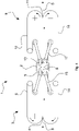
- a processing apparatus has been indicated (see figure 4 ) that comprises, in particular, at least one processing unit 2 that may be configured, for example, to separate portions of material from a continuous web of material.
- the processing unit 2 may be configured for receiving the material to be processed in the form of a single continuous web and for surrendering the processed material in the form of discrete portions separated from the continuous web.
- the processing unit 2 may comprise, in particular, at least one shearing unit with at least one shearing tool.
- processing unit 2 could be of another type, in particular provided with other types of tool.
- the processing unit 2 could be configured, for example, for receiving material to be processed in the form of a single continuous web and for surrendering processed material still in the form of a single continuous web, or could be configured for receiving material to be processed in the form of a discrete portions arranged one after the other.
- the processing apparatus 1 may be used, in particular, for actuating a method for the production of electrical energy storage devices.
- the processing apparatus 1 may be used for processing material (in the form of a web) comprising at least one separator for electrodes.
- the processing apparatus 1 may comprise, in particular, at least one first conveying device 3 (upstream of the processing unit) that comprises at least one first inlet 4 for material and at least one first outlet 5 for material.
- the first conveying device 3 may comprise, as in this embodiment, at least one first flexible element 6 (belt, chain, web, rope, cable, mat etc) that is slidable in a closed loop.
- first flexible element 6 belt, chain, web, rope, cable, mat etc
- the first flexible element 6 may be arranged, in particular, for conveying the material from the first inlet 4 to the first outlet 5.
- the first conveying device 3 may comprise, in particular, driving means (for example at least one first motor) for driving sliding of the first flexible element 6.
- the first flexible element 6 may be configured, as in this embodiment, with variable geometry.
- the geometry of the first flexible element 6 may be so controlled as to vary at least the position of the first outlet 5 (the position of the first inlet 4 could remain fixed).
- the first conveying device 3 may comprise, in particular, at least one first support system that supports the closed loop first flexible element 6.
- the first support system may comprise, in particular, at least one system of motion transmission members 7, for example members (pulleys) that are rotatable around their own rotation axis.
- This system may comprise, for example, at least one drive member connected to a drive shaft to command movement and/or one or more guide or transmission members that can rotate freely on their own axis.
- the first support system may comprise a movable first portion 8 that is movable in a controlled manner to modify the geometry of the closed loop of the first flexible element 6 to maintain the length thereof substantially constant.
- the movable first portion 8 of the first support system may be arranged so as to vary the position of the first outlet 5.
- the movable first portion 8 may comprise, for example, a (stiff) connecting element that connects (integrally) the rotation axes of at least two motion transmission members 7.
- the movable first portion 8 may be connected to a driving system (with at least one motor, not shown) for controlling the movement of the movable first portion 8 and, consequently, the variation of the geometry of the closed loop of the first flexible element 6.
- the first support system may be configured in such a manner that the movements of the first portion 8 (with consequent integral movement of the rotation axes of at least two motion transmission members 7) causes a variation of the geometry of the closed loop without modifying the length thereof.
- the first support system may be provided with tensioning means (not shown) for controlling (maintaining constant) the tensioning of the first flexible element 6.
- Figures 1 to 3 show three different positions of the movable first portion 8 with three different geometries of the closed loop.
- the processing apparatus 1 may be configured, in particular, so that the aforesaid processing unit 2 is arranged near the first outlet 5 for receiving the material coming from the first conveying device 3.
- the processing unit 2 may be drivable, in particular, with the possibility of adopting at least one engagement position (schematised in Figure 5B ), for example a material cutting position, in which it engages the material.
- the processing unit 2 may be drivable, in particular, with the possibility of adopting at least one disengaged position (schematised in Figures 5A and 5C ) in which it leaves the material free.
- the processing unit 2 may be, as in this embodiment, movable together (integrally) with the first outlet 5.
- the processing apparatus 1 may comprise, in particular, control means configured for controlling the movement of an assembly that comprises the processing unit 2 and the first outlet 5 and/or the movable first portion 8.
- control means configured for controlling the movement of an assembly that comprises the processing unit 2 and the first outlet 5 and/or the movable first portion 8.
- the processing unit 2 may be connected to the movable first portion 8 so as to move integrally therewith.
- the first portion 8 and the processing unit 2 are connected together by a mechanical connection, although it is possible to provide an electronic connection (by electronic control means).
- the processing unit 2 may comprise, for example, a first end fixed to the rotation axis of at least one of the motion transmission members 7 on which the movable first portion 8 is constrained, such that the first portion 8 of the first support system may be integrally movable with the processing unit 2.
- the processing apparatus 1 may comprise, in particular, at least one second conveying device 9 (downstream of the processing unit 2) that comprises at least one second inlet 10 for the material and at least one second outlet 11 for the material.
- the second conveying device 9 may comprise, as in this embodiment, at least one second flexible element 12 that is slidable in a closed loop and that may be arranged, in particular, for conveying the material from the second inlet 10 to the second outlet 11.
- the second flexible element 12 may be configured with variable controlled geometry, for example in such a manner as to vary the position of the second inlet 10 (the position of the second outlet 11 could remain fixed).
- the processing unit 2 may be arranged, as in this embodiment, near the second inlet 10 to be able to deliver the material to the second conveying device 9.
- the processing unit 2 may be, in particular, integrally movable with the second inlet 10.
- the second conveying device 9 may comprise, in particular, at least one second support system that supports the closed loop second flexible element 12.
- the second support system may comprise, as in this embodiment, at least one second portion 13 that is movable in a controlled manner and configured for modifying the geometry of the closed loop of the second flexible element 12 to maintain the length thereof substantially constant.
- the movable second portion 13 may be arranged, as in this embodiment, in such a manner as to vary the position of the second inlet 13.
- the second portion 13 may be, in particular, integrally movable with the processing unit 2.
- the aforesaid assembly which comprises the processing unit 2 and the first portion 8 (together with the first outlet 5), may also comprise the second portion 13 (together with the second inlet 10).
- the first conveying device 3 (upstream of the processing unit) may comprise, in particular, a third flexible element 14 that is slidable in a closed loop and that may comprise, as in this embodiment, a branch coupled with a branch of the first flexible element 6.
- the material advances, dragged by the first conveying device 3, passing between the aforesaid branch of the first flexible element 6 and the aforesaid branch of the third flexible element 14.
- the third flexible element 14 may be configured, as in this embodiment, with variable controlled geometry, in particular with variation of geometry coordinated with the variation of geometry of the first flexible element 6.
- the first conveying device 3 may comprise, in particular, at least one third support system that may support, as in this embodiment, the closed loop third flexible element 14.
- the third support system may comprise, in particular, at least one movable third portion 15 that is movable so as to modify the geometry of the closed loop of the third flexible element 14 to maintain the length thereof substantially constant.
- the movable third portion 15 may be arranged, as in this embodiment, in such a manner as to vary the position of the first outlet 5.
- the third portion 15 may be, in particular, integrally movable with the processing unit 2.
- the aforesaid assembly which may comprise the processing unit 2 and/or the first portion 8 (together with the first outlet 5) and/or the second portion 13 (together with the second inlet 10), may comprise the third portion 15.
- the second conveying device 9 (downstream of the processing unit) may comprise, as in this embodiment, at least one fourth flexible element 16 that is slidable in a closed loop and that may comprise, in particular, at least one branch coupled with at least one branch of the second flexible element 12.
- the material that advances, dragged by the second conveying device 9, may pass between the aforesaid branch of the second flexible element 12 and the aforesaid branch of the fourth flexible element 16.
- the fourth flexible element 16 may be configured, as in this embodiment, with variable geometry in which the variation of geometry may be, in particular, controlled in coordination with the variation of the geometry of the second flexible element 12.
- the second conveying device 9 may comprise, in particular, a fourth support system that supports the closed loop fourth flexible element 16.
- the fourth support system may comprise, as in this embodiment, a fourth portion 17 that is movable so as to modify the geometry of the closed loop to maintain the length thereof substantially constant.
- the movable fourth portion 17 may be arranged, in particular, in such a manner as to vary the position of the second inlet 10.
- the fourth portion 17 may be, in particular, integrally movable with the movement of the processing unit 2.
- the aforesaid assembly which may comprise the processing unit 2 and/or the first portion 8 (together with the first outlet 5) and/or the second portion 13 (together with the second inlet 10) and/or the third portion 15 (together with the first outlet 5), may comprise the fourth portion 17.
- the second support system and/or the third support system and/or the fourth support system may each be configured in an analogous manner to the first support system disclosed above.
- the movable second portion 13 and/or the movable third portion 15 and/or the movable fourth portion 17 may each comprise, a (stiff) connecting element that connects (integrally) the rotation axes of at least two motion transmission members of the support system of the respective second and/or third and/or fourth flexible element.
- the processing unit 2 may comprise, for example, a second end and/or a third end and/or a fourth end fixed to the rotation axis of at least one of the motion transmission members to which the second portion 13 and/or the third portion 15 and/or the fourth portion 17 is constrained.
- the control means may be configured for controlling the sliding of the first flexible element 6 (in particular the rotation of the driving member for driving the support system of the first flexible element 6) and/or driving the processing unit 2 (in particular the movements between the aforesaid positions of engaging the material, or work positions, and positions of disengagement from the material, or rest positions).
- control means may be configured for controlling, in a coordinated manner, the sliding of the first flexible element 6 (in particular the rotation of the driving member for driving the system of motion transmission members 7), the driving of the processing unit 2 (in particular the moving of the processing tool between the work and rest positions) and the movement of the aforesaid assembly comprising the processing unit 2 and/or the movable first portion 8 (in particular the movement that determines both the variation of the geometry of the closed loop, and the forward and/or backward movements of the processing unit 2) and/or one or more of the other movable portions 13, 15, 17.
- control means may be configured for controlling the sliding of the second flexible element 12 in a coordinated manner with the sliding of the first flexible element 6, the drive of the processing unit 2 and the movement of the aforesaid assembly.
- the control means may comprise, in particular, programmable electronic control means (for example an electronic processor) and computer program instructions that are implementable on the electronic control means.
- programmable electronic control means for example an electronic processor
- computer program instructions that are implementable on the electronic control means.
- the control means may be configured, in particular, to perform a work cycle in which the material advances continuously in an advancement direction (through the effect of the sliding of the first flexible element).
- the work cycle may comprise, as in this embodiment, at least one forward step in which the processing unit advances in the advancement direction and at least one return step in which the processing unit moves backward in the opposite direction.
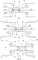
- FIGs 5A to 5C three different moments of the forward step are illustrated, in which the assembly that comprises the processing unit 2 advances together with the material S (at the same speed, at least for a considerable portion of the forward step) with an initial moment ( Figure 5A ), an intermediate moment ( Figure 5B ) and a final moment ( Figure 5C ).
- the return step involves moving backward the aforesaid assembly, from the position of Figure 5C to that of Figure 5A , in a direction opposite the material advancement direction S that meantime continues to advance (in particular at a constant advancement speed for at least one portion).
- the (programmed) work cycle may provide, as in this embodiment, for the processing unit 2 adopting the engagement position ( Figure 5B ) during at least one part of the forward step and adopting the disengaged position ( Figures 5A and 5C ) during at least one part of the return step (in particular during the entire return step).
- the control means may control in a coordinated manner the sliding of the first flexible element 6 (and/or of the second flexible element 12 and/or of the third flexible element 14 and/or of the fourth flexible element 16), the drive of the processing unit 2 and the movement of the processing unit 2 (together with the rest of the assembly), so that the processing unit 2 can engage the material S whilst the processing unit 2 advances at the same speed as the material S.
- the apparatus may be so controlled that the separated (cut) material advances, at least for a period of time, at a speed that is greater than the rest of the material. It is possible, for example, to accelerate the sliding of the first flexible element 6 (and/or of the third flexible element 14) and/or slow the sliding of the second flexible element 12 (and/or of the fourth flexible element 16), for a certain (relatively short) period of time, immediately after the processing unit has carried out the separation (shearing) and the processing unit assumes the disengaged position of the material, in particular to space the separated material apart from the rest of the material.
- the material S may be commanded to advance at a constant forward speed for at least one part of the forward step and/or to move backwards at a constant return speed for at least one part of the return step.
- the assembly (comprising the processing unit 2) may be commanded to advance at the same speed of the material S in at least one part of the forward step and to move backwards in the return step at a greater return speed (to recover the same initial position of the preceding work cycle) with respect to the speed of the forward step.
- the processing unit 2 may then advance for at least one portion at the same speed as the material S, so that it can process the material S, whilst the latter advances, minimising, or substantially reducing to zero, the relative speed between the processing unit 2 and the material S in the advancement direction.
- first inlet 4 it is possible to provide, as in this embodiment, for the first inlet 4 to remain fixed.
- second outlet 11 it is possible to provide, as in this embodiment, for the second outlet 11 to remain fixed. In this manner the supply of the material to be processed and/or the evacuation of the processed material is particularly facilitated.
- the first conveying device 3 (upstream of the processing unit 2) may comprise an outlet for the material (first outlet 5) that, during advancement of the processing unit 2 in the forward step, may be moved together with the processing unit 2 so as to remain at the same distance from the processing unit 2. More in particular, the first conveying device 3 may comprise an outlet for the material (first outlet 5) that, during moving backwards of the processing unit 2 in the return step, may be moved together with the processing unit 2 so as to remain at the same distance from the processing unit 2.
- the second conveying device 9 (downstream of the processing unit 2) may comprise an inlet for material (the second inlet 10) that, during advancement of the processing unit 2 in the forward step, may be moved together with the processing unit 2 so as to remain at the same distance from the processing unit 2. More in particular, the second conveying device 9 may comprise an inlet for material (the second inlet 10) that, during moving backwards of the processing unit 2 in the return step, may be moved together with the processing unit 2 so as to remain at the same distance from the processing unit 2.
- the first conveying device 3 (upstream of the processing unit 2) may comprise an inlet for material (first inlet 4) that, during advancement of the processing unit 2 in the forward step, may always remain fixed in the same position.
- the first conveying device 3 may comprise an inlet for material (first inlet 4) that, during moving backwards of the processing unit 2 in the return step, may always remain fixed in the same position.
- the second conveying device 9 (downstream of the processing unit 2) may comprise an outlet for the material (second outlet 11) that, during advancement of the processing unit 2 in the forward step, may always remain fixed in the same position.
- the second conveying device 9 may comprise an outlet for the material (second outlet 11) that, during moving backwards of the processing unit 2 in the return step, may always remain fixed in the same position.
- first conveying device 3 upstream of the processing unit 2 it is possible to use any other conveying device comprising, in particular, a first inlet for material (for example a fixed position inlet) for the material and a first outlet that may be moved (with a forward and backward motion) integrally with the processing unit 2.
- second conveying device 9 downstream of the processing unit 2 it is possible to use any other conveying device comprising, in particular, a second inlet that may be moved (with a forward and backward motion) integrally with the processing unit 2 and a second outlet (for example a fixed position outlet).
- the material is conveyed by friction, in particular by passing through two coupled branches of two slidable elements that cooperate together.
- conveying devices for example with a single (in particular closed loop) sliding element, for example a conveyor belt, or a conveyor of the suction type, or yet other types.
- the two flexible elements 14 and 16 of the example of Fig. 4 are integrated with each other (for example by joining the two lower branches in Fig. 4 ) so as to form a single closed loop flexible element that defines both the first outlet 5 and the second inlet 10 (a single closed loop element defines the two inlets 4 and 10 and the two outlets 5 and 11).
Landscapes
- Life Sciences & Earth Sciences (AREA)
- Forests & Forestry (AREA)
- Engineering & Computer Science (AREA)
- Mechanical Engineering (AREA)
- Absorbent Articles And Supports Therefor (AREA)
- Cell Separators (AREA)
- Details Of Cutting Devices (AREA)
- Delivering By Means Of Belts And Rollers (AREA)
- Advancing Webs (AREA)
- Framework For Endless Conveyors (AREA)
- Polarising Elements (AREA)
- Confectionery (AREA)
- Acyclic And Carbocyclic Compounds In Medicinal Compositions (AREA)
Claims (15)
- Appareil de traitement (1) destiné à traiter un matériau en bande continue, ledit appareil comprenant :- un premier dispositif de transport (3) comprenant une première entrée (4), une première sortie (5) et un premier élément souple sans fin coulissant (6), ledit premier élément souple (6) étant agencé pour transporter un matériau en bande continue (S) de ladite première entrée (4) à ladite première sortie (5), ledit premier élément souple (6) étant configuré avec une géométrie variable qui est contrôlée de manière à faire varier au moins la position de ladite première sortie (5) ;- une unité de traitement (2) disposée près de ladite première sortie (5) pour recevoir le matériau en bande continue (S) depuis ledit premier dispositif de transport (3), ladite unité de traitement (2) pouvant être déplacée entre au moins une position de prise dans laquelle elle entre en prise avec le matériau en bande continue (S) et au moins une position de désengagement, ladite unité de traitement (2) étant mobile conjointement avec ladite première sortie (5) ; caractérisé par- un moyen de contrôle configurés pour contrôler d'une manière coordonnée le coulissement dudit premier élément souple (6), le déplacement de ladite unité de traitement (2) et le mouvement conjoint de ladite unité de traitement (2) avec ladite première sortie (5), pour effectuer un cycle de traitement dans lequel le matériau en bande continue (S) avance d'une manière continue dans une direction avant, dans lequel ledit cycle de traitement comprend au moins une étape vers l'avant dans laquelle ladite unité de traitement (2) avance dans ladite direction avant conjointement avec ladite première sortie (5) et au moins une étape de retour dans laquelle ladite unité de traitement (2) revient dans la direction opposée conjointement avec ladite première sortie (5), dans lequel ladite unité de traitement (2) prend ladite position de prise pendant au moins une partie de ladite étape vers l'avant pour entrer en prise avec le matériau en bande continue (S) lorsqu'elle avance avec ce même matériau, dans lequel ladite unité de traitement (2) prend ladite position de désengagement pendant au moins une partie de ladite étape de retour.
- Appareil selon la revendication 1, dans lequel ledit premier dispositif de transport (3) comprend un premier système de support qui supporte ledit premier élément souple (6) et qui comprend une première partie (8) qui est mobile d'une manière contrôlée pour modifier la géométrie dudit premier élément souple (6) tout en maintenant sensiblement constante sa longueur, ladite première partie (8) dudit premier système de support étant agencée de manière à faire varier la position de ladite première sortie (5).
- Appareil selon la revendication 1, dans lequel ladite première partie (8) est contrainte de bouger conjointement avec ladite unité de traitement (2).
- Appareil selon l'une quelconque des revendications précédentes, comprenant un deuxième dispositif de transport (9) comprenant une deuxième entrée (10), une deuxième sortie (11) et un deuxième élément souple sans fin coulissant (12) qui est agencé pour transporter un matériau de ladite deuxième entrée (10) à ladite deuxième sortie (11) et qui est configuré avec une géométrie variable qui est contrôlée de manière à faire varier la position de ladite deuxième entrée (10).
- Appareil selon la revendication 4, dans lequel ladite unité de traitement (2) est disposée près de ladite deuxième entrée (10) pour délivrer le matériau (S) audit deuxième dispositif de transport (9).
- Appareil selon la revendication 4 ou 5, dans lequel ladite unité de traitement (2) est mobile conjointement avec ladite deuxième entrée (10).
- Appareil selon l'une quelconque des revendications 4 à 6, dans lequel le deuxième dispositif de transport (9) comprend un deuxième système de support qui supporte ledit deuxième élément souple (12) et qui comprend une deuxième partie (13) qui est mobile d'une manière contrôlée pour modifier la géométrie dudit deuxième élément souple (12) tout en maintenant sensiblement constante sa longueur, ladite deuxième partie (13) étant agencée de manière à faire varier la position de ladite deuxième entrée (10).
- Appareil selon la revendication 7, dans lequel ladite deuxième partie (13) est contrainte de bouger conjointement avec ladite unité de traitement (2).
- Appareil selon l'une quelconque des revendications précédentes, dans lequel ledit premier dispositif de transport (3) comprend un troisième élément souple sans fin coulissant (14) qui comprend une branche couplée à une branche dudit premier élément souple (6), dans lequel le matériau (S) passe entre ladite branche dudit premier élément souple (6) et ladite branche dudit troisième élément souple (14), dans lequel ledit troisième élément souple (14) est éventuellement configuré avec une géométrie variable qui est contrôlée en coordination avec ledit premier élément souple (6).
- Appareil selon la revendication 9, dans lequel ledit premier dispositif de transport (3) comprend un troisième système de support qui supporte ledit troisième élément souple (14) et qui comprend une troisième partie (15) qui est mobile de manière à modifier la géométrie dudit troisième élément souple (14) en maintenant sensiblement constante sa longueur, ladite troisième partie (15) étant agencée de manière à faire varier la position de ladite première sortie (5), dans lequel ladite troisième partie (15) est éventuellement contrainte de bouger conjointement avec ladite unité de traitement (2).
- Appareil selon l'une quelconque des revendications 4 à 10, dans lequel ledit deuxième dispositif de transport (9) comprend un quatrième élément souple sans fin coulissant (16) qui comprend une branche couplée à une branche dudit deuxième élément souple (12), dans lequel le matériau (S) passe entre ladite branche dudit deuxième élément souple (12) et ladite branche dudit quatrième élément souple (16), dans lequel ledit quatrième élément souple (16) est éventuellement configuré avec une géométrie variable qui est contrôlée en coordination avec ledit deuxième élément souple (12).
- Appareil selon la revendication 11, dans lequel ledit deuxième dispositif de transport (9) comprend un quatrième système de support qui supporte ledit quatrième élément souple (16) et qui comprend une quatrième partie (17) qui est mobile de manière à modifier la géométrie dudit quatrième élément souple (16) en maintenant sensiblement constante sa longueur, ladite quatrième partie (17) étant agencée de manière à faire varier la position de ladite deuxième entrée (10), dans lequel ladite quatrième partie (17) est éventuellement contrainte de bouger conjointement avec ladite unité de traitement (2).
- Appareil selon l'une quelconque des revendications précédentes, dans lequel ladite au moins une unité de traitement (2) est configurée pour séparer des parties de matériau du matériau en bande continue, dans lequel ledit moyen de contrôle est éventuellement configuré de telle sorte que la partie séparée de matériau avance, après séparation, à une vitesse supérieure à celle du reste du matériau, pour espacer la partie séparée du reste du matériau.
- Appareil selon la revendication 13, dans lequel ladite au moins une unité de traitement (2) comprend au moins une unité de cisaillement.
- Procédé de production de dispositifs de stockage d'énergie électrique, caractérisé par l'utilisation d'un appareil de traitement (1) selon l'une quelconque des revendications précédentes pour le traitement d'un matériau (S) comprenant au moins un séparateur pour électrodes.
Applications Claiming Priority (2)
| Application Number | Priority Date | Filing Date | Title |
|---|---|---|---|
| IT102016000094439A IT201600094439A1 (it) | 2016-09-20 | 2016-09-20 | Apparato di lavorazione |
| PCT/IB2017/055207 WO2018055465A1 (fr) | 2016-09-20 | 2017-08-30 | Appareil de traitement |
Publications (2)
| Publication Number | Publication Date |
|---|---|
| EP3523231A1 EP3523231A1 (fr) | 2019-08-14 |
| EP3523231B1 true EP3523231B1 (fr) | 2022-07-13 |
Family
ID=58159311
Family Applications (1)
| Application Number | Title | Priority Date | Filing Date |
|---|---|---|---|
| EP17765487.8A Active EP3523231B1 (fr) | 2016-09-20 | 2017-08-30 | Appareil de traitement |
Country Status (9)
| Country | Link |
|---|---|
| US (1) | US10815090B2 (fr) |
| EP (1) | EP3523231B1 (fr) |
| JP (1) | JP6968871B2 (fr) |
| KR (1) | KR102363107B1 (fr) |
| CN (1) | CN109562900B (fr) |
| HU (1) | HUE059332T2 (fr) |
| IT (1) | IT201600094439A1 (fr) |
| PL (1) | PL3523231T3 (fr) |
| WO (1) | WO2018055465A1 (fr) |
Families Citing this family (5)
| Publication number | Priority date | Publication date | Assignee | Title |
|---|---|---|---|---|
| CN111217180A (zh) * | 2020-01-17 | 2020-06-02 | 广东利元亨智能装备股份有限公司 | 送料装置、贴胶装置和送料方法 |
| IT202100021314A1 (it) * | 2021-08-05 | 2023-02-05 | Manz Italy Srl | Apparato e relativo metodo di avvolgimento di nastri di materiale per la produzione di dispositivi di accumulo di energia elettrica |
| US12246921B2 (en) | 2021-10-08 | 2025-03-11 | Ferag Ag | Transportation device |
| CH719027A1 (de) * | 2021-10-08 | 2023-04-14 | Ferag Ag | Transportvorrichtung. |
| CN114873340A (zh) * | 2022-04-14 | 2022-08-09 | 中国原子能科学研究院 | 用于测量核孔膜的物理参数的设备和方法 |
Citations (1)
| Publication number | Priority date | Publication date | Assignee | Title |
|---|---|---|---|---|
| EP3558655A1 (fr) * | 2016-12-23 | 2019-10-30 | VMI Holland B.V. | Dispositif de coupe et procédé pour découper une longueur d'une bande continue pour former un élément de pneu |
Family Cites Families (17)
| Publication number | Priority date | Publication date | Assignee | Title |
|---|---|---|---|---|
| GB1014490A (en) * | 1962-09-28 | 1965-12-22 | T & T Vicars Ltd | Improvements in or relating to conveyors |
| JPS5446472U (fr) * | 1977-09-07 | 1979-03-30 | ||
| US4429602A (en) * | 1980-09-04 | 1984-02-07 | Vits-Maschinenbau Gmbh | Method of crosscutting a web and stacking the cut sheets, and impact-type crosscutter for webs with sheet stacker |
| IT1196115B (it) * | 1984-05-23 | 1988-11-10 | Olm Off Mecc Spa | Taglierina perfezionata per il taglio di sfogliato di legno o simili |
| JPS62100361A (ja) * | 1985-10-24 | 1987-05-09 | Panafacom Ltd | タ−ミナルプリンタにおける用紙のインデツクス装置 |
| FR2757297B1 (fr) * | 1996-12-18 | 1999-03-05 | Thomson Multimedia Sa | Procede et dispositif d'etiquetage de region |
| DE10102073A1 (de) * | 2001-01-17 | 2002-07-18 | Sundwig Gmbh | Vorrichtung zum Querteilen von Metallbändern |
| NL1027846C2 (nl) * | 2004-12-22 | 2006-06-23 | Vmi Epe Holland | Inrichting voor het opnemen, verplaatsen en plaatsen van strips of stroken flexibel materiaal. |
| CA2563645C (fr) * | 2006-10-11 | 2011-05-17 | Pierre Laganiere | Systeme convoyeur extensible |
| CN101357717B (zh) * | 2008-07-22 | 2011-03-02 | 南京师范大学 | 电池极板分拣机送片装置 |
| TWI398307B (zh) * | 2009-07-09 | 2013-06-11 | Chan Li Machinery Co Ltd | Detection and screening device and its detection and screening method |
| US8281631B1 (en) * | 2009-11-04 | 2012-10-09 | Chun-Liang Chen | Corrugated metal sheet member fabrication system |
| JP5081963B2 (ja) * | 2010-10-19 | 2012-11-28 | 旭マシナリー株式会社 | 光学フィルムの中間搬送装置 |
| IT1403981B1 (it) | 2011-02-17 | 2013-11-08 | Kemet Electronics Italia S R L | Apparato di taglio |
| GB2506774B (en) * | 2011-06-07 | 2017-05-03 | Risco Usa Corp | Machine and method for high speed cutting and portioning of extruded products |
| CN203624676U (zh) * | 2013-12-13 | 2014-06-04 | 无锡先导自动化设备股份有限公司 | 自动贴胶带装置 |
| US9771227B2 (en) * | 2014-11-06 | 2017-09-26 | A.G. Stacker Inc. | Layboy with adjustable lower conveyor and method for operating the layboy |
-
2016
- 2016-09-20 IT IT102016000094439A patent/IT201600094439A1/it unknown
-
2017
- 2017-08-30 HU HUE17765487A patent/HUE059332T2/hu unknown
- 2017-08-30 KR KR1020187038061A patent/KR102363107B1/ko active Active
- 2017-08-30 CN CN201780041124.6A patent/CN109562900B/zh active Active
- 2017-08-30 PL PL17765487.8T patent/PL3523231T3/pl unknown
- 2017-08-30 WO PCT/IB2017/055207 patent/WO2018055465A1/fr not_active Ceased
- 2017-08-30 EP EP17765487.8A patent/EP3523231B1/fr active Active
- 2017-08-30 US US16/327,494 patent/US10815090B2/en active Active
- 2017-08-30 JP JP2019510417A patent/JP6968871B2/ja active Active
Patent Citations (1)
| Publication number | Priority date | Publication date | Assignee | Title |
|---|---|---|---|---|
| EP3558655A1 (fr) * | 2016-12-23 | 2019-10-30 | VMI Holland B.V. | Dispositif de coupe et procédé pour découper une longueur d'une bande continue pour former un élément de pneu |
Also Published As
| Publication number | Publication date |
|---|---|
| PL3523231T3 (pl) | 2022-11-07 |
| CN109562900A (zh) | 2019-04-02 |
| US20190168980A1 (en) | 2019-06-06 |
| US10815090B2 (en) | 2020-10-27 |
| EP3523231A1 (fr) | 2019-08-14 |
| WO2018055465A1 (fr) | 2018-03-29 |
| HUE059332T2 (hu) | 2022-11-28 |
| IT201600094439A1 (it) | 2018-03-20 |
| JP6968871B2 (ja) | 2021-11-17 |
| JP2020502003A (ja) | 2020-01-23 |
| KR20190047661A (ko) | 2019-05-08 |
| KR102363107B1 (ko) | 2022-02-16 |
| CN109562900B (zh) | 2020-10-09 |
Similar Documents
| Publication | Publication Date | Title |
|---|---|---|
| EP3523231B1 (fr) | Appareil de traitement | |
| EP2417029B1 (fr) | Dispositif de delivrance en ligne a mouvement continu | |
| EP2923244B1 (fr) | Assemblage ou traitement par commande numérique informatique de composants | |
| EP2479111B2 (fr) | Appareil pour poser des aliments tranchés dans des conteneurs | |
| EP3694781B1 (fr) | Scie pour rouleaux de tissu avec convoyeur pour des rouleaux avec un controle indépendant pour des pistes et avec longueur variable des segments de convoyeur | |
| EP3087838A1 (fr) | Dispositif de découpage de pâte | |
| CN101293403A (zh) | 用于处理条带状工件的方法和装置 | |
| CN110540016A (zh) | 用于控制制品沿一定路径输送的设备 | |
| US10773321B2 (en) | Method and device for guiding a tool | |
| EP2511213A1 (fr) | Système de transport pour le transport d'un câble | |
| CN105253603B (zh) | 物品搬送装置 | |
| CN104972651A (zh) | 环形织物带拼接装置及其控制方法 | |
| US11135736B2 (en) | Belt forming system | |
| US8608467B2 (en) | Device and method for twisting elongated dough strips | |
| US7625266B2 (en) | Method for phased separation of a sausage strand, separating element and assembly of separating elements | |
| CN209567166U (zh) | 一种受控运行系统和相关的包装机 | |
| EP1360020A1 (fr) | Convoyeur a pinces pour bande metallique | |
| KR20190064620A (ko) | 기계가공 방법 및 장치 | |
| CN104670971A (zh) | 用于制造复合材料幅的机器 |
Legal Events
| Date | Code | Title | Description |
|---|---|---|---|
| STAA | Information on the status of an ep patent application or granted ep patent |
Free format text: STATUS: UNKNOWN |
|
| STAA | Information on the status of an ep patent application or granted ep patent |
Free format text: STATUS: THE INTERNATIONAL PUBLICATION HAS BEEN MADE |
|
| PUAI | Public reference made under article 153(3) epc to a published international application that has entered the european phase |
Free format text: ORIGINAL CODE: 0009012 |
|
| STAA | Information on the status of an ep patent application or granted ep patent |
Free format text: STATUS: REQUEST FOR EXAMINATION WAS MADE |
|
| 17P | Request for examination filed |
Effective date: 20190701 |
|
| AK | Designated contracting states |
Kind code of ref document: A1 Designated state(s): AL AT BE BG CH CY CZ DE DK EE ES FI FR GB GR HR HU IE IS IT LI LT LU LV MC MK MT NL NO PL PT RO RS SE SI SK SM TR |
|
| AX | Request for extension of the european patent |
Extension state: BA ME |
|
| DAV | Request for validation of the european patent (deleted) | ||
| DAX | Request for extension of the european patent (deleted) | ||
| STAA | Information on the status of an ep patent application or granted ep patent |
Free format text: STATUS: EXAMINATION IS IN PROGRESS |
|
| 17Q | First examination report despatched |
Effective date: 20210520 |
|
| RIC1 | Information provided on ipc code assigned before grant |
Ipc: B26D 5/20 20060101ALI20211223BHEP Ipc: B26D 1/00 20060101ALI20211223BHEP Ipc: B26D 1/60 20060101ALI20211223BHEP Ipc: B65H 20/06 20060101AFI20211223BHEP |
|
| GRAP | Despatch of communication of intention to grant a patent |
Free format text: ORIGINAL CODE: EPIDOSNIGR1 |
|
| STAA | Information on the status of an ep patent application or granted ep patent |
Free format text: STATUS: GRANT OF PATENT IS INTENDED |
|
| INTG | Intention to grant announced |
Effective date: 20220203 |
|
| GRAS | Grant fee paid |
Free format text: ORIGINAL CODE: EPIDOSNIGR3 |
|
| GRAA | (expected) grant |
Free format text: ORIGINAL CODE: 0009210 |
|
| STAA | Information on the status of an ep patent application or granted ep patent |
Free format text: STATUS: THE PATENT HAS BEEN GRANTED |
|
| AK | Designated contracting states |
Kind code of ref document: B1 Designated state(s): AL AT BE BG CH CY CZ DE DK EE ES FI FR GB GR HR HU IE IS IT LI LT LU LV MC MK MT NL NO PL PT RO RS SE SI SK SM TR |
|
| REG | Reference to a national code |
Ref country code: CH Ref legal event code: EP |
|
| REG | Reference to a national code |
Ref country code: DE Ref legal event code: R096 Ref document number: 602017059453 Country of ref document: DE |
|
| REG | Reference to a national code |
Ref country code: AT Ref legal event code: REF Ref document number: 1504186 Country of ref document: AT Kind code of ref document: T Effective date: 20220815 |
|
| REG | Reference to a national code |
Ref country code: IE Ref legal event code: FG4D |
|
| REG | Reference to a national code |
Ref country code: SE Ref legal event code: TRGR |
|
| REG | Reference to a national code |
Ref country code: LT Ref legal event code: MG9D |
|
| REG | Reference to a national code |
Ref country code: NL Ref legal event code: MP Effective date: 20220713 |
|
| REG | Reference to a national code |
Ref country code: HU Ref legal event code: AG4A Ref document number: E059332 Country of ref document: HU |
|
| PG25 | Lapsed in a contracting state [announced via postgrant information from national office to epo] |
Ref country code: RS Free format text: LAPSE BECAUSE OF FAILURE TO SUBMIT A TRANSLATION OF THE DESCRIPTION OR TO PAY THE FEE WITHIN THE PRESCRIBED TIME-LIMIT Effective date: 20220713 Ref country code: PT Free format text: LAPSE BECAUSE OF FAILURE TO SUBMIT A TRANSLATION OF THE DESCRIPTION OR TO PAY THE FEE WITHIN THE PRESCRIBED TIME-LIMIT Effective date: 20221114 Ref country code: NO Free format text: LAPSE BECAUSE OF FAILURE TO SUBMIT A TRANSLATION OF THE DESCRIPTION OR TO PAY THE FEE WITHIN THE PRESCRIBED TIME-LIMIT Effective date: 20221013 Ref country code: NL Free format text: LAPSE BECAUSE OF FAILURE TO SUBMIT A TRANSLATION OF THE DESCRIPTION OR TO PAY THE FEE WITHIN THE PRESCRIBED TIME-LIMIT Effective date: 20220713 Ref country code: LV Free format text: LAPSE BECAUSE OF FAILURE TO SUBMIT A TRANSLATION OF THE DESCRIPTION OR TO PAY THE FEE WITHIN THE PRESCRIBED TIME-LIMIT Effective date: 20220713 Ref country code: LT Free format text: LAPSE BECAUSE OF FAILURE TO SUBMIT A TRANSLATION OF THE DESCRIPTION OR TO PAY THE FEE WITHIN THE PRESCRIBED TIME-LIMIT Effective date: 20220713 Ref country code: FI Free format text: LAPSE BECAUSE OF FAILURE TO SUBMIT A TRANSLATION OF THE DESCRIPTION OR TO PAY THE FEE WITHIN THE PRESCRIBED TIME-LIMIT Effective date: 20220713 Ref country code: ES Free format text: LAPSE BECAUSE OF FAILURE TO SUBMIT A TRANSLATION OF THE DESCRIPTION OR TO PAY THE FEE WITHIN THE PRESCRIBED TIME-LIMIT Effective date: 20220713 |
|
| REG | Reference to a national code |
Ref country code: AT Ref legal event code: MK05 Ref document number: 1504186 Country of ref document: AT Kind code of ref document: T Effective date: 20220713 |
|
| PG25 | Lapsed in a contracting state [announced via postgrant information from national office to epo] |
Ref country code: IS Free format text: LAPSE BECAUSE OF FAILURE TO SUBMIT A TRANSLATION OF THE DESCRIPTION OR TO PAY THE FEE WITHIN THE PRESCRIBED TIME-LIMIT Effective date: 20221113 Ref country code: HR Free format text: LAPSE BECAUSE OF FAILURE TO SUBMIT A TRANSLATION OF THE DESCRIPTION OR TO PAY THE FEE WITHIN THE PRESCRIBED TIME-LIMIT Effective date: 20220713 Ref country code: GR Free format text: LAPSE BECAUSE OF FAILURE TO SUBMIT A TRANSLATION OF THE DESCRIPTION OR TO PAY THE FEE WITHIN THE PRESCRIBED TIME-LIMIT Effective date: 20221014 |
|
| REG | Reference to a national code |
Ref country code: CH Ref legal event code: PL |
|
| REG | Reference to a national code |
Ref country code: DE Ref legal event code: R097 Ref document number: 602017059453 Country of ref document: DE |
|
| PG25 | Lapsed in a contracting state [announced via postgrant information from national office to epo] |
Ref country code: SM Free format text: LAPSE BECAUSE OF FAILURE TO SUBMIT A TRANSLATION OF THE DESCRIPTION OR TO PAY THE FEE WITHIN THE PRESCRIBED TIME-LIMIT Effective date: 20220713 Ref country code: RO Free format text: LAPSE BECAUSE OF FAILURE TO SUBMIT A TRANSLATION OF THE DESCRIPTION OR TO PAY THE FEE WITHIN THE PRESCRIBED TIME-LIMIT Effective date: 20220713 Ref country code: MC Free format text: LAPSE BECAUSE OF FAILURE TO SUBMIT A TRANSLATION OF THE DESCRIPTION OR TO PAY THE FEE WITHIN THE PRESCRIBED TIME-LIMIT Effective date: 20220713 Ref country code: LU Free format text: LAPSE BECAUSE OF NON-PAYMENT OF DUE FEES Effective date: 20220830 Ref country code: LI Free format text: LAPSE BECAUSE OF NON-PAYMENT OF DUE FEES Effective date: 20220831 Ref country code: DK Free format text: LAPSE BECAUSE OF FAILURE TO SUBMIT A TRANSLATION OF THE DESCRIPTION OR TO PAY THE FEE WITHIN THE PRESCRIBED TIME-LIMIT Effective date: 20220713 Ref country code: CZ Free format text: LAPSE BECAUSE OF FAILURE TO SUBMIT A TRANSLATION OF THE DESCRIPTION OR TO PAY THE FEE WITHIN THE PRESCRIBED TIME-LIMIT Effective date: 20220713 Ref country code: CH Free format text: LAPSE BECAUSE OF NON-PAYMENT OF DUE FEES Effective date: 20220831 Ref country code: AT Free format text: LAPSE BECAUSE OF FAILURE TO SUBMIT A TRANSLATION OF THE DESCRIPTION OR TO PAY THE FEE WITHIN THE PRESCRIBED TIME-LIMIT Effective date: 20220713 |
|
| REG | Reference to a national code |
Ref country code: BE Ref legal event code: MM Effective date: 20220831 |
|
| PLBE | No opposition filed within time limit |
Free format text: ORIGINAL CODE: 0009261 |
|
| STAA | Information on the status of an ep patent application or granted ep patent |
Free format text: STATUS: NO OPPOSITION FILED WITHIN TIME LIMIT |
|
| PG25 | Lapsed in a contracting state [announced via postgrant information from national office to epo] |
Ref country code: SK Free format text: LAPSE BECAUSE OF FAILURE TO SUBMIT A TRANSLATION OF THE DESCRIPTION OR TO PAY THE FEE WITHIN THE PRESCRIBED TIME-LIMIT Effective date: 20220713 Ref country code: EE Free format text: LAPSE BECAUSE OF FAILURE TO SUBMIT A TRANSLATION OF THE DESCRIPTION OR TO PAY THE FEE WITHIN THE PRESCRIBED TIME-LIMIT Effective date: 20220713 |
|
| 26N | No opposition filed |
Effective date: 20230414 |
|
| PG25 | Lapsed in a contracting state [announced via postgrant information from national office to epo] |
Ref country code: AL Free format text: LAPSE BECAUSE OF FAILURE TO SUBMIT A TRANSLATION OF THE DESCRIPTION OR TO PAY THE FEE WITHIN THE PRESCRIBED TIME-LIMIT Effective date: 20220713 |
|
| P01 | Opt-out of the competence of the unified patent court (upc) registered |
Effective date: 20230530 |
|
| PG25 | Lapsed in a contracting state [announced via postgrant information from national office to epo] |
Ref country code: IE Free format text: LAPSE BECAUSE OF NON-PAYMENT OF DUE FEES Effective date: 20220830 |
|
| PG25 | Lapsed in a contracting state [announced via postgrant information from national office to epo] |
Ref country code: SI Free format text: LAPSE BECAUSE OF FAILURE TO SUBMIT A TRANSLATION OF THE DESCRIPTION OR TO PAY THE FEE WITHIN THE PRESCRIBED TIME-LIMIT Effective date: 20220713 |
|
| PG25 | Lapsed in a contracting state [announced via postgrant information from national office to epo] |
Ref country code: BE Free format text: LAPSE BECAUSE OF NON-PAYMENT OF DUE FEES Effective date: 20220831 |
|
| PG25 | Lapsed in a contracting state [announced via postgrant information from national office to epo] |
Ref country code: CY Free format text: LAPSE BECAUSE OF FAILURE TO SUBMIT A TRANSLATION OF THE DESCRIPTION OR TO PAY THE FEE WITHIN THE PRESCRIBED TIME-LIMIT Effective date: 20220713 |
|
| PG25 | Lapsed in a contracting state [announced via postgrant information from national office to epo] |
Ref country code: MK Free format text: LAPSE BECAUSE OF FAILURE TO SUBMIT A TRANSLATION OF THE DESCRIPTION OR TO PAY THE FEE WITHIN THE PRESCRIBED TIME-LIMIT Effective date: 20220713 |
|
| PG25 | Lapsed in a contracting state [announced via postgrant information from national office to epo] |
Ref country code: TR Free format text: LAPSE BECAUSE OF FAILURE TO SUBMIT A TRANSLATION OF THE DESCRIPTION OR TO PAY THE FEE WITHIN THE PRESCRIBED TIME-LIMIT Effective date: 20220713 |
|
| PG25 | Lapsed in a contracting state [announced via postgrant information from national office to epo] |
Ref country code: BG Free format text: LAPSE BECAUSE OF FAILURE TO SUBMIT A TRANSLATION OF THE DESCRIPTION OR TO PAY THE FEE WITHIN THE PRESCRIBED TIME-LIMIT Effective date: 20220713 |
|
| PG25 | Lapsed in a contracting state [announced via postgrant information from national office to epo] |
Ref country code: MT Free format text: LAPSE BECAUSE OF FAILURE TO SUBMIT A TRANSLATION OF THE DESCRIPTION OR TO PAY THE FEE WITHIN THE PRESCRIBED TIME-LIMIT Effective date: 20220713 |
|
| PGFP | Annual fee paid to national office [announced via postgrant information from national office to epo] |
Ref country code: PL Payment date: 20240806 Year of fee payment: 8 |
|
| PGFP | Annual fee paid to national office [announced via postgrant information from national office to epo] |
Ref country code: HU Payment date: 20260224 Year of fee payment: 9 |
|
| PGFP | Annual fee paid to national office [announced via postgrant information from national office to epo] |
Ref country code: SE Payment date: 20260224 Year of fee payment: 9 |
|
| PGFP | Annual fee paid to national office [announced via postgrant information from national office to epo] |
Ref country code: GB Payment date: 20260224 Year of fee payment: 9 |
|
| PGFP | Annual fee paid to national office [announced via postgrant information from national office to epo] |
Ref country code: DE Payment date: 20260226 Year of fee payment: 9 |
|
| PGFP | Annual fee paid to national office [announced via postgrant information from national office to epo] |
Ref country code: IT Payment date: 20260224 Year of fee payment: 9 |
|
| PGFP | Annual fee paid to national office [announced via postgrant information from national office to epo] |
Ref country code: FR Payment date: 20260225 Year of fee payment: 9 |