EP3529570B1 - Telemetric fitting - Google Patents
Telemetric fitting Download PDFInfo
- Publication number
- EP3529570B1 EP3529570B1 EP17861373.3A EP17861373A EP3529570B1 EP 3529570 B1 EP3529570 B1 EP 3529570B1 EP 17861373 A EP17861373 A EP 17861373A EP 3529570 B1 EP3529570 B1 EP 3529570B1
- Authority
- EP
- European Patent Office
- Prior art keywords
- magnetic field
- liquid
- level
- ferromagnetic element
- telemetric fitting
- Prior art date
- Legal status (The legal status is an assumption and is not a legal conclusion. Google has not performed a legal analysis and makes no representation as to the accuracy of the status listed.)
- Active
Links
Images


Classifications
-
- G—PHYSICS
- G01—MEASURING; TESTING
- G01F—MEASURING VOLUME, VOLUME FLOW, MASS FLOW OR LIQUID LEVEL; METERING BY VOLUME
- G01F23/00—Indicating or measuring liquid level or level of fluent solid material, e.g. indicating in terms of volume or indicating by means of an alarm
- G01F23/0007—Indicating or measuring liquid level or level of fluent solid material, e.g. indicating in terms of volume or indicating by means of an alarm for discrete indicating and measuring
-
- G—PHYSICS
- G01—MEASURING; TESTING
- G01F—MEASURING VOLUME, VOLUME FLOW, MASS FLOW OR LIQUID LEVEL; METERING BY VOLUME
- G01F23/00—Indicating or measuring liquid level or level of fluent solid material, e.g. indicating in terms of volume or indicating by means of an alarm
- G01F23/30—Indicating or measuring liquid level or level of fluent solid material, e.g. indicating in terms of volume or indicating by means of an alarm by floats
- G01F23/32—Indicating or measuring liquid level or level of fluent solid material, e.g. indicating in terms of volume or indicating by means of an alarm by floats using rotatable arms or other pivotable transmission elements
- G01F23/38—Indicating or measuring liquid level or level of fluent solid material, e.g. indicating in terms of volume or indicating by means of an alarm by floats using rotatable arms or other pivotable transmission elements using magnetically actuated indicating means
-
- G—PHYSICS
- G01—MEASURING; TESTING
- G01F—MEASURING VOLUME, VOLUME FLOW, MASS FLOW OR LIQUID LEVEL; METERING BY VOLUME
- G01F23/00—Indicating or measuring liquid level or level of fluent solid material, e.g. indicating in terms of volume or indicating by means of an alarm
-
- G—PHYSICS
- G01—MEASURING; TESTING
- G01F—MEASURING VOLUME, VOLUME FLOW, MASS FLOW OR LIQUID LEVEL; METERING BY VOLUME
- G01F23/00—Indicating or measuring liquid level or level of fluent solid material, e.g. indicating in terms of volume or indicating by means of an alarm
- G01F23/30—Indicating or measuring liquid level or level of fluent solid material, e.g. indicating in terms of volume or indicating by means of an alarm by floats
- G01F23/56—Indicating or measuring liquid level or level of fluent solid material, e.g. indicating in terms of volume or indicating by means of an alarm by floats using elements rigidly fixed to, and rectilinearly moving with, the floats as transmission elements
- G01F23/62—Indicating or measuring liquid level or level of fluent solid material, e.g. indicating in terms of volume or indicating by means of an alarm by floats using elements rigidly fixed to, and rectilinearly moving with, the floats as transmission elements using magnetically actuated indicating means
-
- G—PHYSICS
- G01—MEASURING; TESTING
- G01F—MEASURING VOLUME, VOLUME FLOW, MASS FLOW OR LIQUID LEVEL; METERING BY VOLUME
- G01F23/00—Indicating or measuring liquid level or level of fluent solid material, e.g. indicating in terms of volume or indicating by means of an alarm
- G01F23/30—Indicating or measuring liquid level or level of fluent solid material, e.g. indicating in terms of volume or indicating by means of an alarm by floats
- G01F23/64—Indicating or measuring liquid level or level of fluent solid material, e.g. indicating in terms of volume or indicating by means of an alarm by floats of the free float type without mechanical transmission elements
- G01F23/72—Indicating or measuring liquid level or level of fluent solid material, e.g. indicating in terms of volume or indicating by means of an alarm by floats of the free float type without mechanical transmission elements using magnetically actuated indicating means
-
- H—ELECTRICITY
- H04—ELECTRIC COMMUNICATION TECHNIQUE
- H04Q—SELECTING
- H04Q9/00—Arrangements in telecontrol or telemetry systems for selectively calling a substation from a main station, in which substation desired apparatus is selected for applying a control signal thereto or for obtaining measured values therefrom
-
- G—PHYSICS
- G01—MEASURING; TESTING
- G01F—MEASURING VOLUME, VOLUME FLOW, MASS FLOW OR LIQUID LEVEL; METERING BY VOLUME
- G01F23/00—Indicating or measuring liquid level or level of fluent solid material, e.g. indicating in terms of volume or indicating by means of an alarm
- G01F23/80—Arrangements for signal processing
- G01F23/802—Particular electronic circuits for digital processing equipment
-
- H—ELECTRICITY
- H04—ELECTRIC COMMUNICATION TECHNIQUE
- H04Q—SELECTING
- H04Q2209/00—Arrangements in telecontrol or telemetry systems
- H04Q2209/40—Arrangements in telecontrol or telemetry systems using a wireless architecture
-
- H—ELECTRICITY
- H04—ELECTRIC COMMUNICATION TECHNIQUE
- H04Q—SELECTING
- H04Q2209/00—Arrangements in telecontrol or telemetry systems
- H04Q2209/80—Arrangements in the sub-station, i.e. sensing device
- H04Q2209/88—Providing power supply at the sub-station
- H04Q2209/886—Providing power supply at the sub-station using energy harvesting, e.g. solar, wind or mechanical
Definitions
- the disclosure herein generally relates to a telemetric fitting for a liquid-level gauge attached to a vessel.
- vapour Within the pressure vessel is an interface between the liquefied gas fuel and the vapour thereof.
- the vapour is located above the liquefied gas fuel and within an upper part of the pressure vessel.
- a vapour outlet in the form of a vapour outlet valve assembly may be attached to the upper part of the pressure vessel.
- the quantity of liquefied gas fuel within a pressure vessel may be determined using a liquid-level gauge in the form of a float-level gauge, an example of which if shown in figure 1 and generally indicated by the numeral 10.
- the float-level gauge of figure 1 is used with LPG bulk storage tanks. Manufacturers of float-level gauges include ROCHESTER, TAYLOR and COTRAKO brand float-level gauges.
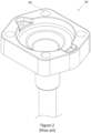
- the float-level gauge comprises a float 12 connected to a stem 14 via a movable joint 16, and a head 18 from which the stem 14 depends.
- the head 18 is shown in further detail in a top perspective view thereof in figure 2 .
- the level float-gauge 10 penetrates a pressure vessel wall and the head 18 is externally attached thereto with bolts that pass through bolt passageways 20 to a flange or other suitable mount that is integrated with the pressure vessel, for example by welds or screws.
- a seal that surrounds the penetrating stem 14 may be sandwiched between the head 18 and a flange integrated with the pressure vessel wall.
- the float 12 follows the interface between the liquefied gas fuel and the vapour thereof.
- a magnet located at the head 18 is operationally coupled to the float 12. Movement of the float 12 is transmitted to the magnet via a gear system at the joint 16. Vertical movement of the float 12 is transformed to a rotation of the magnet at the head 18, and consequently a rotation of the magnet's magnetic field.
- the magnet is mounted to rotate around the stem axis.
- the magnetic field may be followed by a user-visible external needle, the orientation of which may indicate the height of the float and the interface that the float follows.
- the use of the magnet enables measurement of the quantity of liquefied gas fuel within the pressure vessel while maintaining a high strength seal, enhancing safety.
- pressure vessels may be fitted with a pressure gauge for determining the quantity of fluid therein.
- a pressure gauge for determining the quantity of fluid therein.
- the user may contact a gas supply company to refill the pressure vessel with liquefied gas fuel.
- liquefied gas fuel the description may generally apply for any suitable type of liquid within a vessel that may or may not be pressurised, for example liquefied ammonia, cryogenic liquids including liquefied natural gas and liquefied permanent gases, and refined petroleum products including petrol, kerosene, and fuel oil.
- fluid-monitoring systems included short-range communications electronics.
- data is transmitted from a fluid monitoring system to a close by communication system which in turn may transmit to, for example, a cellular system.
- the device itself did not include a medium to long-range transmitter.
- antennas of fluid monitoring systems included housings for antennas which were separate from the other electronics components housing.
- an antenna was not housed in the same housing as other electronic components.
- cabling external of the housing, and without, for example, externally exposed electrical connections may corrode.
- WO2014/136071 describes a fluid monitoring system having a housing for housing a cellular modem and also having a separate housing for an antenna that is separate from the housing for the cellular modem.
- EP 1041370 discloses a system for controlling the level of liquid contained in an LPG tank.
- a telemetric fitting for a liquid-level gauge.
- the telemetric fitting is configured to derive liquid-level information from the liquid-level gauge when attached thereto and wirelessly transmit at radio frequencies the liquid-level information.
- the telemetric fitting according to the present invention is specified in appended claim 1. Further embodiments are specified by the dependent claims.
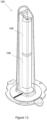
- Figure 3 shows a perspective view of an embodiment of a telemetric fitting for a liquid-level gauge attached to a vessel, the telemetric fitting being generally indicated by the numeral 30.
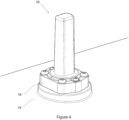
- FIG 4 shows another perspective view of the telemetric fitting 30 attached to the head 18 of a liquid-level gauge attached to a vessel 19.
- the liquid-level gauge in this embodiment is the float-level gauge 10 described above with reference to figures 1 and 2 , however generally any suitable liquid-level gauge may be used.
- the telemetric fitting 30 is configured to derive liquid-level information indicative of a liquid-level from the liquid-level gauge when attached thereto and wirelessly transmit at radio frequencies the liquid-level information.
- the vessel 19 is a pressure vessel in the form of a liquefied gas fuel pressure storage vessel, specifically an LPG bulk storage pressure vessel, however the vessel may be any suitable pressurised or non-pressurised vessel, examples of which include an LPG cylinder, a cryogenic vessel for a permanent gas, liquefied natural gas or other fluid, an ammonia storage vessel, and a refined petroleum product storage vessel.
- a liquefied gas fuel pressure storage vessel specifically an LPG bulk storage pressure vessel
- the vessel may be any suitable pressurised or non-pressurised vessel, examples of which include an LPG cylinder, a cryogenic vessel for a permanent gas, liquefied natural gas or other fluid, an ammonia storage vessel, and a refined petroleum product storage vessel.
- the telemetric fitting comprises a plurality of tabs 31 penetrated by fasteners in the form of screws that attach the telemetric fitting 30 to the gauge head 18 (although any suitable fasteners including bolts, rivets, clips etc or adhesive may be used).
- Figure 5 shows a block diagram showing electronics 58 for the telemetric fitting 30.
- Connecting lines with arrows are information conduits, and connecting lines without arrows are power conduits.
- the electronics comprise at least one printed circuit board assembly (PCBA) 57, 59.
- the electronics 58 comprise a plurality of electrical components, at least some of which are mounted on a printed circuit board of the at least one PCBA 57, 59.
- the plurality of electrical components comprise at least one of a processor 60 in the form of a logic device, in this embodiment a host micro-controller unit 60, an electronic magnetic sensor 64 in the form of an electronic magnetic field angle sensor (which is analogue, however it may alternatively be digital), and a radio 71 in the form of a radio transceiver, the radio comprising at least one of a medium range radio network interface and a long range radio network interface, an antenna 72, and a power switch in the form of a MOSFET 68, indicator lights in the form of at least one LED 66, and an electrical power source in the form of at least one battery 62 that provides power to the radio 71 via the MOSFET 68 and the processor 60.
- the processor 60 is in electrical communication with the MOSFET 68.
- the MOSFET 68 and the processor 60 cooperate to switch off the power to the radio 71 when it is not transmitting liquid-level information or other data.
- Another form of switch for example a relay, may be used instead.
- the radio 71 is within a module, which may consume more power than desired, even when not transmitting. Switching off the power to the module reduces the power consumption of the electronics 58, which may generally extend the life of the at least one battery 62 to, for example, 15 years.
- the electrical power source may comprise an energy harvesting system that harvests mechanical energy (e.g. vibrations), electromagnetic energy (e.g. radio waves, light), or heat.
- the energy harvesting system may comprise a solar cell, or piezo-electric generator.
- Medium-to-long range wireless links enable transmission to centralised data centres, for example, using either private or commercial radio base stations.
- the radio network interface comprises a low power wide area network (LPWAN) interface.
- the LPWAN interface comprises a low-power wide area network radio (LPWAN) integrated circuit 70.
- the LPWAN interface comprises a physical LPWAN interface in communication with the antenna 72.
- An LPWAN is a type of wireless communications network for medium to long range communications at bit rates which are generally, but not necessarily, low, and has low power consumption when compared to cellular communication technologies for voice and high bandwidth data services. Examples of LPWAN include but are not limited to LoRaWAN, and Sigfox.
- the LPWAN radio integrated circuit may be within an LPWAN radio module.
- the range achieved LPWAN depends on many factors, including the presence of obstacles in the transmission path, but ranges of more than 5 km are common, for example 5-10 km.
- Radio 71 comprising another type of medium range radio network interface or long range radio network interface, for example a cellular radio network interface (examples of which include but are not limited to GSM, CDMA, and LTE cellular radio network interfaces), IEEE 802.11 interface (“Wi-Fi”) and a satellite communications interface.
- a cellular radio network interface examples of which include but are not limited to GSM, CDMA, and LTE cellular radio network interfaces
- Wi-Fi IEEE 802.11 interface
- the electronic magnetic field angle sensor 64 may not be sensitive to ambient temperature changes, as magnetic field strength sensors generally are. Consequently, the use of an electronic magnetic field angle sensor 64 may increase accuracy. In alternative embodiments, however, the strength of the magnetic field may be sensed for deriving the liquid-level measurement. Any suitable type of magnetic sensor can be used, for example, a Hall effect sensor. Other types of sensors that may be suitable include a giant magnetoresistance (GMR) sensor, an anisotropic magnetoresistance (AMR) sensor, a tunnelling magnetoresistance (TMR) sensor, and 3D magnetic sensor.
- GMR giant magnetoresistance
- AMR anisotropic magnetoresistance
- TMR tunnelling magnetoresistance
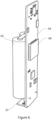
- Figures 6-8 show perspective views of the PCBAs 57 and 59 which are orthogonal to each other and are joined using a board-to-board connector 59 in the form of a header.
- One of the PCBAs 57 and 59 may be a flexible circuit board layer extending from the other.
- Using a vertically disposed PCBA 59 allows the telemetric fitting to have a relatively smaller footprint which may facilitate its use on tanks with many nearby fittings and ports.
- the use of the horizontally disposed PCBA 59 provides a suitable orientation for the electronic magnetic sensor 64 mounted thereto to sense the magnetic field orientation.
- the electronic magnetic sensor 64 may be configured to sense the magnetic field orientation when mounted on the vertically disposed PCBA 59 (for example on a lower edge of PCBA 57), in which case the horizontally disposed PCBA 57 may not be required.
- Figures 9 and 10 show an exploded perspective view and a cutaway view of the telemetric fitting 30 respectively.
- the telemetric fitting 30 has opposite ends 36, 102 with a gauge interface 32 at end 36.
- the gauge interface 32 is configured to derive liquid-level information from a liquid-level gauge using, for example in this embodiment, a liquid-level dependent magnetic field generated by the liquid-level gauge.
- the telemetric fitting 30 is configured such that the magnetic field generated by the liquid-level gauge rotates around a longitudinal axis thereof.
- the magnetic field generated by the liquid-level gauge may be sensed directly by the electronic magnetic field angle sensor 64.
- at least one ferromagnetic element 42, 43 (two in the present embodiment, however other embodiments may have more or less) follows and rotates with the magnetic field, and the magnetic field of the at least one ferromagnetic element 42, 43 is sensed by the electronic magnetic field angle sensor 64.
- the at least one ferroelectric element 42, 43 has a predetermined magnetic field structure in the region of the magnetic sensor 64.
- the magnetic field of the liquid-level gauge may vary considerably more in strength and structure from one gauge to another.
- the at least one ferroelectric element 42, 43 couples to the magnetic field of the liquid-level gauge and may help to produce a more consistent magnetic field structure and strength sensed by the magnetic sensor 64.
- the at least one ferromagnetic element 42, 43 and the electronic magnetic sensor are parts of a magnetic sensor shown approximately in figure 16 , with a more accurate detail thereof shown in figure 17 without magnets.
- the at least one ferromagnetic element 42, 43 is magnetically coupled to the magnetic field generated by magnet 47 within the liquid-level sensor head 18.
- the at least one ferromagnetic element 42, 43 is intermediate the end 36 and the sensor 64 and the PCBA 57.
- the at least one ferromagnetic element 42, 43 comprises at least one magnet in the form of a permanent magnet, however it may comprise a ferromagnetic material, for example iron or cobalt, that is not a permanently magnetised, but temporarily magnetised by the magnetic field generated by the liquid-level gauge.
- the magnetic sensor senses the orientation of the magnetic field generated by the liquid level gauge, which is dependent on the liquid-level within the vessel 19.
- the ferromagnetic element 42 is in this embodiment is one of two magnets 42, 43 arranged symmetrically around a central axis and held by a ferromagnetic element holder 49 in the form of a magnet holder.
- the magnet holder 49 is supported by a journal 41 to form a rotary bearing assembly 45 for rotation of the magnet holder 49 around the longitudinal axis, enabling the magnets 42, 43 to rotate with the liquid-level dependent magnetic field.
- a bearing surface 51 within the magnet holder 49 receives the journal 41.
- the journal 41 is in the form of a peg or spigot, which may be integral with the end 36. The journal 41 penetrates more than halfway through the magnet holder 49, which may provide superior balance.
- the bearing assembly 45 comprises a first bearing component 53 in the form of a thrust bearing at the tip of the journal 41 for supporting the magnet holder 49, and a second bearing component in the form of a radial bearing 55 for orientating the magnet holder 49 to the central axis, especially when one magnet is misaligned or has a magnetic strength that is not equal to the other magnet.
- the magnet holder 49 is held down on the bearing assembly 45 by the magnetic attraction of the at least one magnet 42, 43 to the magnet 47 within the liquid-level sensor head 18, which generally but not necessarily removes the need for a second journal engaged with the other side of the magnet holder 49.
- the surface of the journal 41 and the bearing surfaces 51, 55 comprise dissimilar materials for a low coefficient of friction.
- the materials are selected for a low coefficient of friction to maximise the bearing performance.
- the journal 41 may be polycarbonate and the magnet holder 49 is PolyOxyMethylene ("ACETAL"), however any suitable materials may be used.
- the magnets 42, 43 have opposite magnetic orientation. Since like poles repel and opposite poles attract, this ensures that the magnets 42,43 magnetically couple to the two opposite magnetic poles of shaped arms of the magnet 47 in the head 18, which generates the liquid-level dependent magnetic field. Without the opposite magnetic orientations of the magnets 42, 43, it is possible for the magnets to be 180 degrees in error, which may result in a spurious reading.
- the micro-controller unit 60 receives raw magnetic field information in the form of magnetic field orientation information generated by a magnetic sensor, in this embodiment from an output of the electronic magnetic sensor 64.
- the magnetic field orientation information comprises three voltages from three arms of a bridge within the sensor 64.
- the micro-controller executes a program that comprises an algorithm specified by the sensor manufacturer for calculating magnetic field orientation information indicative of an angle of the magnetic field from the received raw magnetic field information.
- the magnetic field orientation information is indicative of the liquid-level.
- the magnetic field orientation information comprises a string of symbols that encode an angle for the orientation of the magnetic field.
- the micro-controller 60 sends the magnetic field orientation information to the radio for transmission of the liquid level information.
- the radio encapsulates the string of symbols in accordance with the LPWAN protocol and subsequently sends the encapsulated string of symbols, optionally together with telemetric fitting identification information indicative of the identification of the telemetric fitting.
- the LPWAN protocol may include identification information, for example a Sigfox DeviceID or LoRaWAN end-device address.
- the magnetic field orientation information is received by a computer server that can access information about the type of gauge that the telemetric unit 30 is attached to and thus calculate, using the magnetic field orientation information, the liquid-level in a percent of total vessel water volume or generally any suitable other unit, for example volume of remaining liquid in the vessel.
- the server has a data store in the form of a database that associates the identification information of a plurality of telemetric fittings with information about the gauge and/or vessel to which each is attached.
- the database may be populated by keyboard entry, for example.
- the micro-controller unit 60 may have a lookup table stored in memory for associating the sensed magnetic field angle with liquid-level information.
- the liquid-level information may comprise a string of symbols that encode the remaining volume of liquid as a percentage.
- the micro-controller determines the liquid-level information from the lookup table and subsequently sends the liquid level information to the radio for transmission of the liquid level information.
- the micro-controller unit 60 includes software for calculating the liquid level as a function of magnetic field angle. Generally, any suitable algorithm may be used to derive the liquid-level information from the magnetic field information generated by the magnetic sensor.
- the radio encapsulates the string of symbols in accordance with the LPWAN protocol and subsequently sends the encapsulated string of symbols, together with telemetric fitting identification information indicative of the identification of the telemetric fitting.
- the telemetric fitting 30 comprises a two-part transparent exterior housing 38, made of impact-resistant polycarbonate, in which is disposed the electronics 58.
- the housing 38 has a transparent window 39 at the end 36 for viewing the indicator 44 from above. Alternatively, the exterior housing 38 may not be transparent.
- the exterior housing 38 may be generally formed of any suitable material including but not limited to polymers such as nylon, polypropylene and polythene, and ceramics.
- the exterior housing 38 may be formed using any suitable process including but not limited to injection and other types of moulding, milling and three-dimensional printing.
- the indicator may be integral to the magnet holder, removably attached or non removably attached.
- a human readable dial 40 is attached to the exterior housing 38.
- the dial 40 is at least partly transparent to enable the pointer 45 to be viewed.
- the telemetric fitting 30 can include a plurality of dials, each dial having a different visual display, for example, different markings or indicators, different language, different measurement units, different colour, different branding, different warning, or different re-fill level.
- the plurality of different dials may be compatible with a plurality of differently configured liquid-level gauges, and a compatible dial 40 can be chosen to suit a particular liquid-level gauge configuration.
- the plurality of different dials may be compatible with a plurality of differently configured tanks, for example one for vertically-oriented tanks and one for horizontally-oriented tanks, and a compatible dial 40 can be chosen to suit a particular tank configuration.
- the plurality of different dials may be compatible with a plurality of legal jurisdictions and a compatible dial 40 can be chosen to suit a particular jurisdiction.
- the plurality of different dials may comprise a range of visual displays to provide human choices, and a dial can be selected based on, for example, human preference or corporate preference.
- the selected dial 40 can be fitted to the housing 38 when the configuration of the liquid-level gauge and tank is known. For example, an installer may have the option to choose a suitable dial 40 at the installation site to match the configuration of the liquid-level gauge and tank.
- the dial is removable from the housing 38.
- a removable dial provides an option to exchange the dial with another dial, for example if the telemetric fitting 30 is moved to a differently configured liquid-level gauge or tank.
- the dial is attached the housing adjacent the gauge interface 32.
- the indicator 44 cooperates with the dial 40 for indicating the liquid-level in the vessel.
- the dial may have a scale having the percentage of the tank's water volume printed thereon, or may have "FULL", "REFILL” and "EMPTY", colour or other coding for the liquid level.
- the dial is oriented to the longitudinal axis of the telemetric fitting 30 for viewing from above.
- the dial may be moulded or decal. It may be attached by, for example, friction fit or snap fit, with an adhesive or fastener, or generally any suitable way.
- Figure 11 shows a top view of the telemetric fitting 30, the dial 40 and the pointer 45.
- the telemetric fitting 30, and consequently the exterior housing 38 does not extend beyond a perimeter of the gauge head 18 when attached to the liquid-level gauge.
- Some embodiments have a dial with two scales, one for a horizontal tank orientation and another for a vertical tank orientation.
- a scale or other liquid-level coding may be printed on the indicator 44, and anindex or pointer may be printed on the exterior of the housing or otherwise attached thereto.
- the gauge interface 32 is configured to connect with any one of a plurality of differently configured float-level gauge heads 18, including "Junior” and “Senior” style float-level gauges.
- the gauge interface may incorporate features including removable screw mounting tags 31, screw head rims, flanges and location recesses for alignment to "glue-down" gauges to provide compatibility with ROCHESTER, TAYLOR and other four-bolt or screwed-in float-level gauges. Attachment to other compatible gauges may for example be made using an adaptor.
- a magnetic switch 73 in the form of a Hall effect switch is in communication with the processor 60, and can generate a logic level state change in response to the presence of a magnetic field. By approaching the telemetric fitting 30 with a magnet, the Hall effect switch 73 can change state and thus wake up the processor 60 via an interrupt.
- Other types of magnetic switches can be used instead of the Hall effect switch, for example an anisotropic magnetoresistance (AMR) switch or a tunnelling magnetoresistance (TMR) switch.
- AMR anisotropic magnetoresistance
- TMR tunnelling magnetoresistance
- a reed switch is used instead of the Hall effect switch, although it may be more expensive and more fragile than the Hall effect switch.
- the device may be woken up using alternative methods, for example using an infrared sensor and an infrared torch, or an externally accessible switch in the form of a membrane switch.
- the telemetric fitting 100 shown in figure 12 has a plurality of serially spatially arranged batteries 108. Alternatively it may have a single battery or more than two batteries.
- An alternative embodiment of a telemetric fitting 110 is shown in figures 13 - 15 , which has similar and/or identical form and function to the embodiment of figure 3 except where otherwise described or illustrated. Parts in figures 13-15 having similar and/or identical form and/or function to parts in figures 3-12 are similarly numbered.
- the telemetric fitting 110 has a dial 40 attached to an upper end 102 thereof.
- the dial 40 may be, for example, friction fitted to at least one post 104 or attached thereto using adhesive or generally any suitable way.
- the indicator 44 is configured to have a pointer 45 thereof disposed adjacent the dial 40 at the upper end 102.
- An indicator 44 has a bracket 106 that extends longitudinally and is terminated by the inwardly directed pointer 45.
- the pointer may be attached at the top of a central axle in the form of a pin.
- the pointer and pin may be a single piece moulded part.
- a step comprises deriving liquid-level information from a liquid-level gauge 10 attached to the vessel 19 with the telemetric fitting 30 attached to the head 18 of the liquid-level gauge.
- a step comprises the telemetric fitting 30 wirelessly transmitting the liquid-level information so derived.
- the method may comprise a step of attaching the telemetric fitting 30 to the liquid-level gauge 10.
- Transmitting the liquid-level information so derived may comprise transmitting the liquid-level information over a LPWAN.
- Deriving the liquid-level information may comprise deriving the liquid-level information from the liquid-level gauge 10 with a gauge interface 32 of the telemetric fitting 30.
- the gauge interface 32 magnetically derives the liquid-level information from the liquid-level gauge 10.
- the gauge interface 32 may derive the liquid-level information by sensing the liquid-level dependent magnetic field, in this embodiment its orientation, generated by the liquid-level gauge 10.
- An optional step comprises selecting a dial 40 of a plurality of dials for a plurality of differently configured liquid-level gauges and attaching the dial to an exterior housing of the telemetric fitting 30.
Landscapes
- Physics & Mathematics (AREA)
- Fluid Mechanics (AREA)
- General Physics & Mathematics (AREA)
- Engineering & Computer Science (AREA)
- Computer Networks & Wireless Communication (AREA)
- Level Indicators Using A Float (AREA)
Priority Applications (1)
| Application Number | Priority Date | Filing Date | Title |
|---|---|---|---|
| EP23219616.2A EP4417944A1 (en) | 2016-10-21 | 2017-10-21 | A telemetric fitting and a method of telemetric measurement |
Applications Claiming Priority (2)
| Application Number | Priority Date | Filing Date | Title |
|---|---|---|---|
| AU2016904289A AU2016904289A0 (en) | 2016-10-21 | A telemetric fitting and a method of telemetric measurement | |
| PCT/AU2017/051151 WO2018071989A1 (en) | 2016-10-21 | 2017-10-21 | A telemetric fitting and a method of telemetric measurement |
Related Child Applications (1)
| Application Number | Title | Priority Date | Filing Date |
|---|---|---|---|
| EP23219616.2A Division EP4417944A1 (en) | 2016-10-21 | 2017-10-21 | A telemetric fitting and a method of telemetric measurement |
Publications (4)
| Publication Number | Publication Date |
|---|---|
| EP3529570A1 EP3529570A1 (en) | 2019-08-28 |
| EP3529570A4 EP3529570A4 (en) | 2020-06-24 |
| EP3529570B1 true EP3529570B1 (en) | 2024-01-03 |
| EP3529570C0 EP3529570C0 (en) | 2024-01-03 |
Family
ID=62018165
Family Applications (2)
| Application Number | Title | Priority Date | Filing Date |
|---|---|---|---|
| EP23219616.2A Withdrawn EP4417944A1 (en) | 2016-10-21 | 2017-10-21 | A telemetric fitting and a method of telemetric measurement |
| EP17861373.3A Active EP3529570B1 (en) | 2016-10-21 | 2017-10-21 | Telemetric fitting |
Family Applications Before (1)
| Application Number | Title | Priority Date | Filing Date |
|---|---|---|---|
| EP23219616.2A Withdrawn EP4417944A1 (en) | 2016-10-21 | 2017-10-21 | A telemetric fitting and a method of telemetric measurement |
Country Status (5)
| Country | Link |
|---|---|
| US (3) | US11248944B2 (pl) |
| EP (2) | EP4417944A1 (pl) |
| AU (1) | AU2017346942B2 (pl) |
| PL (1) | PL3529570T3 (pl) |
| WO (1) | WO2018071989A1 (pl) |
Families Citing this family (6)
| Publication number | Priority date | Publication date | Assignee | Title |
|---|---|---|---|---|
| PL3529570T3 (pl) * | 2016-10-21 | 2024-04-08 | Silicon Controls Pty Ltd | Urządzenie telemetryczne |
| CN109708727B (zh) * | 2019-03-04 | 2023-12-12 | 江苏多维科技有限公司 | 一种基于磁阻传感器交叉点阵列的数字液位传感器 |
| WO2020216443A1 (en) * | 2019-04-24 | 2020-10-29 | Rosemount Tank Radar Ab | Radar level gauge system and method for controlling the radar level gauge system |
| EP3957898A1 (en) * | 2020-08-20 | 2022-02-23 | Hexagon Ragasco AS | System and method for digitally monitoring a pressure vessel |
| EP4230971A1 (en) * | 2022-02-20 | 2023-08-23 | Hexagon Ragasco AS | Smart composite pressure vessel |
| US20240385024A1 (en) * | 2023-04-23 | 2024-11-21 | Service Insight LLC | Exterior gauge component for fuel level monitoring that is compatible with different tank gauge heads |
Citations (2)
| Publication number | Priority date | Publication date | Assignee | Title |
|---|---|---|---|---|
| WO2002042722A2 (en) * | 2000-11-06 | 2002-05-30 | Trinity Industries, Inc. | Remote monitoring adapter for levelmeter |
| ITMI20122103A1 (it) * | 2012-12-10 | 2014-06-11 | Rivoira S P A | Bombola per gas compressi e liquefatti equipaggiata con un sistema di rilevazione, indicazione e trasmissione del livello della riserva di liquido |
Family Cites Families (47)
| Publication number | Priority date | Publication date | Assignee | Title |
|---|---|---|---|---|
| US943868A (en) * | 1909-07-19 | 1909-12-21 | Arthur S Garlick | Liquid-gage. |
| US1020785A (en) * | 1911-05-05 | 1912-03-19 | Perry E Tanner | Tank-gage. |
| US2584446A (en) * | 1948-07-01 | 1952-02-05 | Rochester Mfg Company | Liquid level gauge |
| US2771774A (en) * | 1953-02-12 | 1956-11-27 | Montedison Spa | Level gauge for enclosed pressure vessels |
| US2795955A (en) * | 1955-09-02 | 1957-06-18 | Rochester Mfg Company Inc | Liquid level gauge |
| US2992560A (en) * | 1956-11-14 | 1961-07-18 | American Radiator & Standard | Liquid level gauge |
| US3198010A (en) * | 1962-02-19 | 1965-08-03 | American Radiator & Standard | Liquid level gauge |
| US3320922A (en) * | 1965-03-15 | 1967-05-23 | J Y Taylor Mfg Company | Indicator head for liquid level gauge and process of making same |
| US3688795A (en) * | 1970-09-14 | 1972-09-05 | Rochester Gauges Inc Of Texas | Liquid level gauge and valve |
| US3739641A (en) * | 1971-05-05 | 1973-06-19 | L Taylor | Remote reading gauge indicator unit |
| US4554494A (en) * | 1984-09-21 | 1985-11-19 | Rochester Gauges, Inc. | Fluid level gauge having magnetic sensor |
| US5311776A (en) * | 1993-04-12 | 1994-05-17 | Rochester Gauges, Inc. | Pre-installation liquid level gauge assembly with thread protector |
| USD379316S (en) * | 1996-03-14 | 1997-05-20 | Rochester Gauges, Inc. | Gauge |
| US6041650A (en) * | 1997-08-26 | 2000-03-28 | Rochester Gauges, Inc. | Liquid level gauge |
| US6336362B1 (en) * | 1998-01-22 | 2002-01-08 | Roy A. Duenas | Method and system for measuring and remotely reporting the liquid level of tanks and the usage thereof |
| IT1309352B1 (it) * | 1999-03-31 | 2002-01-22 | Areagas S R L | Sistema per il controllo del livello di liquido contenuto nei serbatoigpl o simili. |
| US6497145B1 (en) * | 1999-06-17 | 2002-12-24 | Rochester Gauges, Inc. | Float gauge with fixed liquid level gauge |
| US6188022B1 (en) | 1999-06-18 | 2001-02-13 | Ping He | Electrical box mounting system having removable rings |
| US6822565B2 (en) * | 1999-07-20 | 2004-11-23 | Keith A. Thomas | Wireless gauge alert |
| US6564632B2 (en) * | 2001-01-11 | 2003-05-20 | Rochester Gauges, Inc. | Liquid level gauge with removable hall device |
| US20040079152A1 (en) * | 2001-02-01 | 2004-04-29 | Fluent Systems, Llc | Remote fluid level detection system |
| DE20303296U1 (de) * | 2003-02-28 | 2004-07-08 | Robert Bosch Gmbh | Füllstandsensor |
| US7173506B2 (en) * | 2003-04-25 | 2007-02-06 | Rochester Gauges, Inc. | Dial assembly with magnetically biased reed switch |
| US7093485B2 (en) * | 2003-11-17 | 2006-08-22 | Nartron Corporation | Fuel level sensor |
| US7921873B2 (en) * | 2004-01-22 | 2011-04-12 | Rochester Gauges, Inc. | Service valve assembly having a stop-fill device and a liquid level indicating dial |
| EP1628115A1 (en) * | 2004-08-16 | 2006-02-22 | Key Safety Systems, Inc. | Magnetic sensor system |
| EP1691178A1 (en) | 2005-02-11 | 2006-08-16 | Sztek Anstalt | Magnetic rotation detector for use with a liquid level sensor |
| US7441569B2 (en) * | 2005-04-28 | 2008-10-28 | Robertshaw Controls Company | Will call wireless tank level monitoring system |
| US8803683B2 (en) * | 2006-09-13 | 2014-08-12 | Trackpoint Systems, Llc | System, method, and device for measuring and reporting changing levels of liquids in storage tanks |
| EP2087324A4 (en) * | 2006-11-17 | 2010-12-29 | Louis J Jannotta | DEVICE FOR MONITORING THE LIQUID LEVEL IN A MEMORY TANK |
| US8353649B2 (en) | 2007-10-19 | 2013-01-15 | The Monadnock Company | Apparatus and methods for securing a fastener |
| US7690323B2 (en) * | 2007-10-31 | 2010-04-06 | Rochester Gauges, Inc. | Gauge head assembly with non-magnetic insert |
| US20100294037A1 (en) * | 2009-05-21 | 2010-11-25 | Deleo David | Gauge assembly and methods of using same |
| US9068877B2 (en) * | 2011-04-15 | 2015-06-30 | Texas Lfp, Llc | Liquid level sender with adjustable counterweight |
| US9304027B2 (en) * | 2011-04-15 | 2016-04-05 | Texas Lfp, Llc | Angled gauge head for liquid level sending unit |
| WO2014136071A1 (en) | 2013-03-06 | 2014-09-12 | Smart Solutions Limited | Fluid monitoring system |
| CA2891800A1 (en) * | 2014-05-15 | 2015-11-15 | Arthur E. Colvin, Jr. | Wireless fluid sensor |
| MX360033B (es) * | 2015-06-11 | 2018-10-19 | Pedro Gabay Villafana | Dispositivo electronico para la deteccion de campo magnetico que indica nivel de gas en tanques estacionarios y envio de datos en forma inalambrica. |
| US10247589B2 (en) * | 2016-04-21 | 2019-04-02 | KSR IP Holdings, LLC | Fluid level monitor |
| AU2017346943A1 (en) * | 2016-10-21 | 2018-07-05 | Silicon Controls Pty Ltd | An electronic device |
| PL3529570T3 (pl) * | 2016-10-21 | 2024-04-08 | Silicon Controls Pty Ltd | Urządzenie telemetryczne |
| EP3462144B1 (en) * | 2017-09-29 | 2020-08-19 | Aiut Sp. z o.o. | Liquid gas level measuring system |
| US10552721B2 (en) * | 2017-09-29 | 2020-02-04 | Silicon Controls Pty Ltd. | Method and a system for monitoring a quantity related to an asset |
| US10175088B1 (en) * | 2018-01-11 | 2019-01-08 | Rochester Gauges, Inc. | Liquid level gauge with removable indicator assembly |
| EP3557196A1 (en) * | 2018-04-16 | 2019-10-23 | Silicon Controls Pty Ltd | A telemetric fitting and a method of telemetric measurement |
| US10863254B2 (en) * | 2018-07-12 | 2020-12-08 | Silicon Controls Pty Ltd | Telemetric devices and methods of dynamic transmission frequency |
| US20230296420A1 (en) * | 2022-02-06 | 2023-09-21 | Independent Technologies, Llc | Systems and Methods for Monitoring Contents in an Asset |
-
2017
- 2017-10-21 PL PL17861373.3T patent/PL3529570T3/pl unknown
- 2017-10-21 AU AU2017346942A patent/AU2017346942B2/en active Active
- 2017-10-21 EP EP23219616.2A patent/EP4417944A1/en not_active Withdrawn
- 2017-10-21 WO PCT/AU2017/051151 patent/WO2018071989A1/en not_active Ceased
- 2017-10-21 EP EP17861373.3A patent/EP3529570B1/en active Active
-
2018
- 2018-04-16 US US15/953,689 patent/US11248944B2/en active Active
-
2020
- 2020-04-01 US US16/837,347 patent/US11879763B2/en active Active
-
2023
- 2023-07-21 US US18/224,986 patent/US20230366716A1/en active Pending
Patent Citations (2)
| Publication number | Priority date | Publication date | Assignee | Title |
|---|---|---|---|---|
| WO2002042722A2 (en) * | 2000-11-06 | 2002-05-30 | Trinity Industries, Inc. | Remote monitoring adapter for levelmeter |
| ITMI20122103A1 (it) * | 2012-12-10 | 2014-06-11 | Rivoira S P A | Bombola per gas compressi e liquefatti equipaggiata con un sistema di rilevazione, indicazione e trasmissione del livello della riserva di liquido |
Also Published As
| Publication number | Publication date |
|---|---|
| US11879763B2 (en) | 2024-01-23 |
| US20230366716A1 (en) | 2023-11-16 |
| WO2018071989A1 (en) | 2018-04-26 |
| PL3529570T3 (pl) | 2024-04-08 |
| EP3529570A4 (en) | 2020-06-24 |
| AU2017346942A1 (en) | 2018-06-14 |
| US20180238729A1 (en) | 2018-08-23 |
| US11248944B2 (en) | 2022-02-15 |
| EP4417944A1 (en) | 2024-08-21 |
| EP3529570C0 (en) | 2024-01-03 |
| US20200225072A1 (en) | 2020-07-16 |
| AU2017346942B2 (en) | 2018-08-30 |
| EP3529570A1 (en) | 2019-08-28 |
Similar Documents
| Publication | Publication Date | Title |
|---|---|---|
| EP3529570B1 (en) | Telemetric fitting | |
| US20250102119A1 (en) | Systems and Methods for Improved Asset Monitoring via Orientation Measurement | |
| US12456029B2 (en) | Method and a system for monitoring a quantity related to an asset | |
| EP3557196A1 (en) | A telemetric fitting and a method of telemetric measurement | |
| US10724893B2 (en) | Liquid gas level measuring system | |
| EP4200554B1 (en) | System and method for digitally monitoring a pressure vessel | |
| AU2018202632B2 (en) | A Telemetric fitting and a method of telemetric measurement | |
| AU2018202633B9 (en) | An electronic device |
Legal Events
| Date | Code | Title | Description |
|---|---|---|---|
| STAA | Information on the status of an ep patent application or granted ep patent |
Free format text: STATUS: THE INTERNATIONAL PUBLICATION HAS BEEN MADE |
|
| PUAI | Public reference made under article 153(3) epc to a published international application that has entered the european phase |
Free format text: ORIGINAL CODE: 0009012 |
|
| STAA | Information on the status of an ep patent application or granted ep patent |
Free format text: STATUS: REQUEST FOR EXAMINATION WAS MADE |
|
| 17P | Request for examination filed |
Effective date: 20180911 |
|
| AK | Designated contracting states |
Kind code of ref document: A1 Designated state(s): AL AT BE BG CH CY CZ DE DK EE ES FI FR GB GR HR HU IE IS IT LI LT LU LV MC MK MT NL NO PL PT RO RS SE SI SK SM TR |
|
| AX | Request for extension of the european patent |
Extension state: BA ME |
|
| DAV | Request for validation of the european patent (deleted) | ||
| DAX | Request for extension of the european patent (deleted) | ||
| RIN1 | Information on inventor provided before grant (corrected) |
Inventor name: HADDY, JOHN RICHARD Inventor name: NEUMAN, MICHAEL ALEXANDER |
|
| A4 | Supplementary search report drawn up and despatched |
Effective date: 20200525 |
|
| RIC1 | Information provided on ipc code assigned before grant |
Ipc: G01F 23/38 20060101AFI20200516BHEP Ipc: G01F 23/62 20060101ALI20200516BHEP Ipc: G01F 23/30 20060101ALI20200516BHEP Ipc: G01F 23/00 20060101ALI20200516BHEP Ipc: H04Q 9/00 20060101ALI20200516BHEP |
|
| STAA | Information on the status of an ep patent application or granted ep patent |
Free format text: STATUS: EXAMINATION IS IN PROGRESS |
|
| 17Q | First examination report despatched |
Effective date: 20210526 |
|
| GRAP | Despatch of communication of intention to grant a patent |
Free format text: ORIGINAL CODE: EPIDOSNIGR1 |
|
| STAA | Information on the status of an ep patent application or granted ep patent |
Free format text: STATUS: GRANT OF PATENT IS INTENDED |
|
| P01 | Opt-out of the competence of the unified patent court (upc) registered |
Effective date: 20230605 |
|
| INTG | Intention to grant announced |
Effective date: 20230622 |
|
| GRAS | Grant fee paid |
Free format text: ORIGINAL CODE: EPIDOSNIGR3 |
|
| GRAA | (expected) grant |
Free format text: ORIGINAL CODE: 0009210 |
|
| STAA | Information on the status of an ep patent application or granted ep patent |
Free format text: STATUS: THE PATENT HAS BEEN GRANTED |
|
| AK | Designated contracting states |
Kind code of ref document: B1 Designated state(s): AL AT BE BG CH CY CZ DE DK EE ES FI FR GB GR HR HU IE IS IT LI LT LU LV MC MK MT NL NO PL PT RO RS SE SI SK SM TR |
|
| REG | Reference to a national code |
Ref country code: GB Ref legal event code: FG4D |
|
| REG | Reference to a national code |
Ref country code: DE Ref legal event code: R096 Ref document number: 602017078195 Country of ref document: DE |
|
| REG | Reference to a national code |
Ref country code: CH Ref legal event code: EP |
|
| REG | Reference to a national code |
Ref country code: IE Ref legal event code: FG4D |
|
| U01 | Request for unitary effect filed |
Effective date: 20240131 |
|
| P04 | Withdrawal of opt-out of the competence of the unified patent court (upc) registered |
Effective date: 20240205 |
|
| U07 | Unitary effect registered |
Designated state(s): AT BE BG DE DK EE FI FR IT LT LU LV MT NL PT SE SI Effective date: 20240208 |
|
| PG25 | Lapsed in a contracting state [announced via postgrant information from national office to epo] |
Ref country code: ES Free format text: LAPSE BECAUSE OF FAILURE TO SUBMIT A TRANSLATION OF THE DESCRIPTION OR TO PAY THE FEE WITHIN THE PRESCRIBED TIME-LIMIT Effective date: 20240103 |
|
| PG25 | Lapsed in a contracting state [announced via postgrant information from national office to epo] |
Ref country code: ES Free format text: LAPSE BECAUSE OF FAILURE TO SUBMIT A TRANSLATION OF THE DESCRIPTION OR TO PAY THE FEE WITHIN THE PRESCRIBED TIME-LIMIT Effective date: 20240103 |
|
| PG25 | Lapsed in a contracting state [announced via postgrant information from national office to epo] |
Ref country code: IS Free format text: LAPSE BECAUSE OF FAILURE TO SUBMIT A TRANSLATION OF THE DESCRIPTION OR TO PAY THE FEE WITHIN THE PRESCRIBED TIME-LIMIT Effective date: 20240503 |
|
| PG25 | Lapsed in a contracting state [announced via postgrant information from national office to epo] |
Ref country code: GR Free format text: LAPSE BECAUSE OF FAILURE TO SUBMIT A TRANSLATION OF THE DESCRIPTION OR TO PAY THE FEE WITHIN THE PRESCRIBED TIME-LIMIT Effective date: 20240404 |
|
| PG25 | Lapsed in a contracting state [announced via postgrant information from national office to epo] |
Ref country code: HR Free format text: LAPSE BECAUSE OF FAILURE TO SUBMIT A TRANSLATION OF THE DESCRIPTION OR TO PAY THE FEE WITHIN THE PRESCRIBED TIME-LIMIT Effective date: 20240103 Ref country code: RS Free format text: LAPSE BECAUSE OF FAILURE TO SUBMIT A TRANSLATION OF THE DESCRIPTION OR TO PAY THE FEE WITHIN THE PRESCRIBED TIME-LIMIT Effective date: 20240403 |
|
| PG25 | Lapsed in a contracting state [announced via postgrant information from national office to epo] |
Ref country code: CZ Free format text: LAPSE BECAUSE OF FAILURE TO SUBMIT A TRANSLATION OF THE DESCRIPTION OR TO PAY THE FEE WITHIN THE PRESCRIBED TIME-LIMIT Effective date: 20240103 |
|
| PG25 | Lapsed in a contracting state [announced via postgrant information from national office to epo] |
Ref country code: RS Free format text: LAPSE BECAUSE OF FAILURE TO SUBMIT A TRANSLATION OF THE DESCRIPTION OR TO PAY THE FEE WITHIN THE PRESCRIBED TIME-LIMIT Effective date: 20240403 Ref country code: NO Free format text: LAPSE BECAUSE OF FAILURE TO SUBMIT A TRANSLATION OF THE DESCRIPTION OR TO PAY THE FEE WITHIN THE PRESCRIBED TIME-LIMIT Effective date: 20240403 Ref country code: IS Free format text: LAPSE BECAUSE OF FAILURE TO SUBMIT A TRANSLATION OF THE DESCRIPTION OR TO PAY THE FEE WITHIN THE PRESCRIBED TIME-LIMIT Effective date: 20240503 Ref country code: HR Free format text: LAPSE BECAUSE OF FAILURE TO SUBMIT A TRANSLATION OF THE DESCRIPTION OR TO PAY THE FEE WITHIN THE PRESCRIBED TIME-LIMIT Effective date: 20240103 Ref country code: GR Free format text: LAPSE BECAUSE OF FAILURE TO SUBMIT A TRANSLATION OF THE DESCRIPTION OR TO PAY THE FEE WITHIN THE PRESCRIBED TIME-LIMIT Effective date: 20240404 Ref country code: CZ Free format text: LAPSE BECAUSE OF FAILURE TO SUBMIT A TRANSLATION OF THE DESCRIPTION OR TO PAY THE FEE WITHIN THE PRESCRIBED TIME-LIMIT Effective date: 20240103 |
|
| U20 | Renewal fee for the european patent with unitary effect paid |
Year of fee payment: 8 Effective date: 20240828 |
|
| REG | Reference to a national code |
Ref country code: DE Ref legal event code: R097 Ref document number: 602017078195 Country of ref document: DE |
|
| PG25 | Lapsed in a contracting state [announced via postgrant information from national office to epo] |
Ref country code: SM Free format text: LAPSE BECAUSE OF FAILURE TO SUBMIT A TRANSLATION OF THE DESCRIPTION OR TO PAY THE FEE WITHIN THE PRESCRIBED TIME-LIMIT Effective date: 20240103 |
|
| PG25 | Lapsed in a contracting state [announced via postgrant information from national office to epo] |
Ref country code: SK Free format text: LAPSE BECAUSE OF FAILURE TO SUBMIT A TRANSLATION OF THE DESCRIPTION OR TO PAY THE FEE WITHIN THE PRESCRIBED TIME-LIMIT Effective date: 20240103 |
|
| PG25 | Lapsed in a contracting state [announced via postgrant information from national office to epo] |
Ref country code: SM Free format text: LAPSE BECAUSE OF FAILURE TO SUBMIT A TRANSLATION OF THE DESCRIPTION OR TO PAY THE FEE WITHIN THE PRESCRIBED TIME-LIMIT Effective date: 20240103 Ref country code: SK Free format text: LAPSE BECAUSE OF FAILURE TO SUBMIT A TRANSLATION OF THE DESCRIPTION OR TO PAY THE FEE WITHIN THE PRESCRIBED TIME-LIMIT Effective date: 20240103 Ref country code: RO Free format text: LAPSE BECAUSE OF FAILURE TO SUBMIT A TRANSLATION OF THE DESCRIPTION OR TO PAY THE FEE WITHIN THE PRESCRIBED TIME-LIMIT Effective date: 20240103 |
|
| PLBE | No opposition filed within time limit |
Free format text: ORIGINAL CODE: 0009261 |
|
| STAA | Information on the status of an ep patent application or granted ep patent |
Free format text: STATUS: NO OPPOSITION FILED WITHIN TIME LIMIT |
|
| 26N | No opposition filed |
Effective date: 20241007 |
|
| P05 | Withdrawal of opt-out of the competence of the unified patent court (upc) changed |
Free format text: CASE NUMBER: APP_6334/2024 Effective date: 20240208 |
|
| REG | Reference to a national code |
Ref country code: CH Ref legal event code: PL |
|
| PG25 | Lapsed in a contracting state [announced via postgrant information from national office to epo] |
Ref country code: MC Free format text: LAPSE BECAUSE OF FAILURE TO SUBMIT A TRANSLATION OF THE DESCRIPTION OR TO PAY THE FEE WITHIN THE PRESCRIBED TIME-LIMIT Effective date: 20240103 |
|
| PG25 | Lapsed in a contracting state [announced via postgrant information from national office to epo] |
Ref country code: CH Free format text: LAPSE BECAUSE OF NON-PAYMENT OF DUE FEES Effective date: 20241031 |
|
| U20 | Renewal fee for the european patent with unitary effect paid |
Year of fee payment: 9 Effective date: 20251030 |
|
| PGFP | Annual fee paid to national office [announced via postgrant information from national office to epo] |
Ref country code: GB Payment date: 20251024 Year of fee payment: 9 |
|
| PGFP | Annual fee paid to national office [announced via postgrant information from national office to epo] |
Ref country code: IE Payment date: 20251021 Year of fee payment: 9 |
|
| PGFP | Annual fee paid to national office [announced via postgrant information from national office to epo] |
Ref country code: PL Payment date: 20251008 Year of fee payment: 9 |
|
| PG25 | Lapsed in a contracting state [announced via postgrant information from national office to epo] |
Ref country code: CY Free format text: LAPSE BECAUSE OF FAILURE TO SUBMIT A TRANSLATION OF THE DESCRIPTION OR TO PAY THE FEE WITHIN THE PRESCRIBED TIME-LIMIT; INVALID AB INITIO Effective date: 20171021 |
|
| PG25 | Lapsed in a contracting state [announced via postgrant information from national office to epo] |
Ref country code: HU Free format text: LAPSE BECAUSE OF FAILURE TO SUBMIT A TRANSLATION OF THE DESCRIPTION OR TO PAY THE FEE WITHIN THE PRESCRIBED TIME-LIMIT; INVALID AB INITIO Effective date: 20171021 |