EP3530170A1 - Halteplatte mit zentriervorrichtung - Google Patents
Halteplatte mit zentriervorrichtung Download PDFInfo
- Publication number
- EP3530170A1 EP3530170A1 EP18158368.3A EP18158368A EP3530170A1 EP 3530170 A1 EP3530170 A1 EP 3530170A1 EP 18158368 A EP18158368 A EP 18158368A EP 3530170 A1 EP3530170 A1 EP 3530170A1
- Authority
- EP
- European Patent Office
- Prior art keywords
- holding plate
- vacuum cleaner
- passage opening
- centering device
- bag
- Prior art date
- Legal status (The legal status is an assumption and is not a legal conclusion. Google has not performed a legal analysis and makes no representation as to the accuracy of the status listed.)
- Granted
Links
Images


Classifications
-
- A—HUMAN NECESSITIES
- A47—FURNITURE; DOMESTIC ARTICLES OR APPLIANCES; COFFEE MILLS; SPICE MILLS; SUCTION CLEANERS IN GENERAL
- A47L—DOMESTIC WASHING OR CLEANING; SUCTION CLEANERS IN GENERAL
- A47L9/00—Details or accessories of suction cleaners, e.g. mechanical means for controlling the suction or for effecting pulsating action; Storing devices specially adapted to suction cleaners or parts thereof; Carrying-vehicles specially adapted for suction cleaners
- A47L9/10—Filters; Dust separators; Dust removal; Automatic exchange of filters
- A47L9/14—Bags or the like; Rigid filtering receptacles; Attachment of, or closures for, bags or receptacles
- A47L9/1427—Means for mounting or attaching bags or filtering receptacles in suction cleaners; Adapters
- A47L9/1436—Connecting plates, e.g. collars, end closures
-
- A—HUMAN NECESSITIES
- A47—FURNITURE; DOMESTIC ARTICLES OR APPLIANCES; COFFEE MILLS; SPICE MILLS; SUCTION CLEANERS IN GENERAL
- A47L—DOMESTIC WASHING OR CLEANING; SUCTION CLEANERS IN GENERAL
- A47L9/00—Details or accessories of suction cleaners, e.g. mechanical means for controlling the suction or for effecting pulsating action; Storing devices specially adapted to suction cleaners or parts thereof; Carrying-vehicles specially adapted for suction cleaners
- A47L9/10—Filters; Dust separators; Dust removal; Automatic exchange of filters
- A47L9/14—Bags or the like; Rigid filtering receptacles; Attachment of, or closures for, bags or receptacles
Definitions
- the invention relates to a holding plate for a vacuum cleaner bag.
- Such retaining plates are known in many forms and have a passage or filling opening through which the connecting piece of a vacuum cleaner can be inserted into the vacuum cleaner bag.
- Such vacuum cleaner can have very different diameters.
- an elastic seal or a sealing ring is often used.
- Such seals are usually made of rubber or a thermoplastic elastomer (TPE). They may be formed integrally with the retaining plate or as a separate component on the retaining plate, under the retaining plate or in the filter bag.
- Cardboard holding plates in which pre-cut parts can be cut out to match the hole diameter to the vacuum nozzle, are also known.
- a vacuum cleaner bag in which an elastic rubber layer is disposed between a holding plate and the vacuum cleaner bag, which is reinforced by a further rigid material layer.
- a dust collection bag is bonded directly to a polymeric material seal.
- the DE 10 2010 060 353 A1 describes a vacuum cleaner bag, comprising a flat, elastic sealing element which is arranged inside and / or outside the bag wall.
- a vacuum cleaner bag is known in which a flexible sealing ring with the bag, and the retaining plate is welded to the sealing ring.
- the DE 10 2007 062 028 B4 describes a dust filter bag in which a layer of rubber-elastic material forms a protruding sealing ring on the inside of the filter bag.
- the relative arrangement of a holding plate to a vacuum cleaner socket received in it in the case of an unfilled, vacuum cleaner bag mounted in the housing of a vacuum cleaner referred to as a "reference position".
- the vacuum cleaner nozzle In the reference position, the vacuum cleaner nozzle is usually centered in the filling opening, that is, in the plane in which the filling opening extends, the distance between the vacuum cleaner nozzle and the edge of the filling opening is substantially constant along the entire circumference of the vacuum cleaner nozzle.
- the seal closes the vacuum cleaner neck in the reference position evenly around its circumference. Thus, the sealing properties of the holding plate in the reference position are best.
- the holding plate when filling the vacuum cleaner bag with dust due to the weight of the Suction material moves in a radial direction relative to the reference position.
- "radially” designates directions which lie in the plane in which the filling opening extends.
- the vacuum cleaner socket itself is usually not moved by the weight of the suction material, since it is additionally fixed during operation by the vacuum cleaner housing, which has a much greater rigidity than the retaining plate.
- Such a radial displacement of the retaining plate leads, in particular, to the fact that the filling opening is displaced from the reference position relative to the vacuum cleaner neck received in the retaining plate. This often leads to a deformation of the seal and thus to a deterioration of the sealing properties.
- the retainer plate may shift into its holder when the vacuum cleaner is opened to check the level of the vacuum cleaner bag, which often involves removing the vacuum cleaner nozzle from the bag. This, in turn, results in a radial displacement of the vacuum cleaner nozzle and filling opening relative to one another when closing the apparatus, and in consequence to the above-described negative effects on the sealing properties.
- the object of the invention is therefore to provide a holding plate, which allows a reliable seal.
- the holding plate comprises a sealing element, as well as a base plate, in which a passage opening is formed.
- the passage opening may be formed in particular circular. But there are other forms of the passage opening possible, for example, they may have an oval, in particular ellipsoidal or rectangular shape.
- the retaining plate can be attached to a holding device in a vacuum cleaner housing.
- the vacuum cleaner filter bag with the help of the holding plate via a vacuum cleaner side connecting piece be pushed.
- the sealing element is intended to prevent or limit the escape of dust from the vacuum cleaner filter bag by sealing the area between the inner edge of the passage opening and the outside of a connecting piece of the vacuum cleaner.
- the sealing element may consist of rubber and / or TPE and / or of the material of the vacuum cleaner filter bag. But it can also consist of any other material which has sufficient elasticity for the necessary sealing effect.
- the sealing element may be molded onto the retaining plate.
- the holding plate comprises a centering device, which extends at least partially along the edge of the passage opening and comprises at least a first spring element.
- the spring element when deformed in the radial direction, the spring element exerts a restoring force directed counter to the deformation.
- the centering device ensures by means of the restoring force that the holding plate is held relative to the vacuum cleaner neck in the reference position and / or returned to the reference position.
- the deformation of the spring element generates a spring force, which is transmitted to the vacuum cleaner neck. Since this, as stated above, is fixed by the vacuum cleaner housing results in the resulting, acting from the vacuum cleaner nozzle on the retaining plate, counterforce in a displacement of the retaining plate which is opposite to the original radial displacement.
- the spring element can be formed from a deformed region of the holding plate, in particular the base plate.
- the deformed region may preferably be deformed wave-shaped, wherein such deformation may include one or more waves. Under a wave while a survey and / or depression is to be understood perpendicular to the main extension plane of the holding plate. In addition, a planar region that adjoins an elevation and / or depression may also be part of the wave. The profile of such a survey may be, for example, V- or U-shaped. If the deformed area contains several waves, the individual waves can have the same profile or different profiles. In the case of multiple waves, all waves may consist of elevations or depressions, or elevations and depressions may alternate. The individual waves can adjoin one another directly or they can be separated from one another by undeformed areas of the holding plate.
- the waves can be arranged concentrically with respect to the passage opening. It means concentrically that the waves are substantially parallel to the edge of the passage opening.
- the deformed region directly causes the deformed region to assume spring properties. Furthermore, the thus deformed area can be compressed be, and therefore allows the inclusion of vacuum cleaner nozzle with different diameters. Instead of waves, the deformed region may also include other structures that impart spring properties to the region.
- the spring element can be formed by the wave-shaped deformation of a circular ring sector of the holding plate, ie by a segment of the holding plate, which, starting from the center of the passage opening, is formed by two different radii and an intermediate annulus.
- the retaining plate may be formed in several pieces.
- the Zentierelement can be glued or welded to the base plate.
- the holding plate may be integrally formed, in particular, the centering device may be formed integrally with the base plate.
- the centering device can at least partially form the edge of the passage opening.
- the retaining plate may further comprise at least a second spring element.
- the arrangement of the spring elements may in particular be designed so that it has no rotational symmetry with respect to the passage opening.
- an n-fold rotational symmetry of the arrangement of the spring elements with respect to the passage opening is to be understood that the arrangement of the spring elements by a rotation of 360 ° / n about an axis corresponding to the central axis of the vacuum cleaner nozzle in the reference position, transferred to itself can.
- a "simple" rotational symmetry is synonymous with no rotational symmetry.
- the spring elements can be the same size or have different sizes. In particular, they may have different dimensions in the circumferential direction of the passage opening. Furthermore, the spring elements may be spaced apart in the circumferential direction or be separated from each other only by incisions. In other words, between each two spring elements lie an undeformed region of the holding plate or a free space.
- the centering device of the holding plate may continue to be formed as a diaphragm spring.
- a diaphragm spring here describes a spring which extends substantially in a main plane of extent, wherein the extent in this plane (length, width) is many times greater than in a direction perpendicular to this plane (thickness).
- the diaphragm spring has a restoring force perpendicular to its main plane of extent.
- the holding plate may comprise a thermoplastic.
- the centering device may consist wholly or partly of a thermoplastic.
- the spring elements may consist of a thermoplastic.
- a thermoplastic is to be understood as meaning a thermoplastic which is not a thermoplastic elastomer.
- the thermoplastic may be, for example, polyethylene terephthalate (PET), polycarbonate (PC), hard polyvinyl chloride (rigid PVC), polypropylene (PP), polyethylene (PE) or polyactate (PLA).
- the thermoplastic may be a recycled plastic, such as recycled PET (rPET) or recycled PP (rPP). As a result, the environmental compatibility of the holding plate can be improved.
- the holding plate can be made by thermoforming or deep drawing. Also, a production by injection molding is possible.
- the invention further provides a vacuum cleaner filter bag according to claim 11, comprising a bag wall and one of the holding plates described above.
- the retaining plate may thus have one or more of the features described above.
- the bag wall of the vacuum cleaner filter bag may comprise one or more filter material layers, in particular one or more nonwoven fabric layers.
- Vacuum cleaner filter bag with such a bag wall of several filter material layers are for example from EP 2 011 556 or the EP 0 960 645 known.
- a material for the nonwoven fabric layers a wide variety of plastics can be used, for example polypropylene and / or polyester.
- the position of the bag wall to be connected to the holding plate may be a nonwoven layer.
- the bag wall of the vacuum cleaner filter bag may also comprise or consist of plastic recyclate. For example, the bag wall as in the EP 3 219 376 A1 be described described.
- nonwoven fabric is used according to the definition according to ISO standard ISO9092: 1988 or CEM standard EN29092.
- nonwoven fabric or nonwoven fabric and nonwoven fabric in the field of production of nonwoven fabrics are delimited from one another as follows and also to be understood in the sense of the present invention.
- To produce a nonwoven fabric fibers and / or filaments are used.
- the loose or loose and still unbound fibers and / or filaments are referred to as fleece or nonwoven web.
- non-woven binding step such a nonwoven fabric finally forms a nonwoven which has sufficient strength to be wound into rolls, for example.
- a nonwoven fabric is self-supporting by the solidification.
- the bag wall may have a passage opening, in particular wherein the passage opening of the bag wall is arranged in alignment with the passage opening of the base plate. Through the passage opening in the base plate and the passage opening in the bag wall, an inflow opening can be formed, through which the air to be purified can flow into the interior of the vacuum cleaner filter bag.
- the vacuum cleaner filter bag may additionally comprise one or more sealing elements which supplement the sealing effect of the centering device.
- the sealing elements can be arranged in the bag and / or between the bag and the holding plate and / or on the holding plate.
- the sealing elements may be made of rubber, and / or of TPE and / or of the material of the vacuum cleaner filter bag. But they can also consist of any other material, which have sufficient elasticity for the necessary sealing effect.
- the invention further provides a vacuum cleaner bag according to claim 12, comprising a bag wall, at least one sealing element, and a retaining plate.
- the holding plate comprises a base plate, in which a passage opening is formed, and a centering device which extends at least partially along the edge of the passage opening and comprises at least a first spring element. The spring element upon deformation in the radial direction of a deformation of the opposing restoring force.
- the at least one sealing element is not part of the retaining plate, but a separate component.
- the at least one sealing element can be arranged in the bag and / or between the bag and the holding plate.
- the bag wall, the sealing element and the centering device can each have one or more of the features described above.
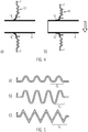
- FIG. 1a schematically shows a conventional support plate 1 with a passage opening 2 and a mounted on the support plate 1 sealing element 3 in plan view.
- a vacuum cleaner 4 is inserted in the passage opening 2 in the passage opening 2.
- FIG. 1b the holding plate 1 is shown with vacuum cleaner 4 in the reference position in a sectional view. It can be seen that the sealing element 3 completes the vacuum cleaner 4 completely.
- Figure 1c shows the support plate 1 with inserted vacuum cleaner 4 after a shift in the radial direction, for example, due to the weight of sucked in a vacuum cleaner bag suction, which is illustrated by the downward arrow.
- a gap 5 has formed between the sealing element 3 and the vacuum cleaner nozzle 4, through which dust can escape from the vacuum cleaner bag into the interior of the vacuum cleaner.
- FIG. 2 shows the schematic structure of an exemplary vacuum cleaner filter bag.
- the filter bag comprises a bag wall 6, a holding plate 7, and an inflow opening, through which the air to be filtered flows into the filter bag.
- the inflow opening is formed here by a passage opening 8 in the base plate of the holding plate 7 and a passage opening arranged in the bag wall 6 in alignment therewith.
- the holding plate 7 serves to fix the Vacuum cleaner filter bag in a corresponding holder in a housing of a vacuum cleaner.
- the bag wall 6 comprises at least one nonwoven fabric layer, for example of a melt-spun fine fiber spunbonded nonwoven fabric (meltblown nonwoven fabric) or a spunbonded nonwoven spunbonded nonwoven fabric.
- a melt-spun fine fiber spunbonded nonwoven fabric meltblown nonwoven fabric
- a spunbonded nonwoven spunbonded nonwoven fabric spunbonded nonwoven fabric
- the holding plate 7 comprises a base plate made of a thermoplastic material.
- recycled plastic material such as recycled polypropylene (rPP) or recycled polyethylene terephthalate (rPET) may be used for the baseplate.
- recycled plastic used for the purposes of the present invention is synonymous with plastic recyclates.
- plastic recyclates For a conceptual definition reference is made to the standard DIN EN 15347: 2007.
- FIG. 3 A plan view of an exemplary holding plate used in conjunction with a filter bag as in FIG. 2 can be used as shown in FIG. 3 shown. This is the holding plate 7 with through opening 8 can be seen.
- the base plate of the holding plate 7 is here shown schematically rectangular, but may have any shapes that may correspond in particular with the corresponding holding device in the vacuum cleaner housing.
- FIG. 3 a centering device 9 as part of the holding plate 7.
- the centering device 9 is shown here as formed integrally with the base plate of the holding plate 7, but it may also be a separate element, which is connected for example by gluing and / or welding to the holding plate 7.
- the centering device extends completely around the circumference of the passage opening 8 around, but it may also be limited to a part of the circumference.
- the centering device 9 comprises in FIG. 3 four spring elements 10, 11, 12, 13, which are separated by cuts 14 from each other.
- the centering device 9 may also comprise a base plate on which the spring elements are attached, for example, by gluing, screwing or welding.
- the spring elements may be separate elements, which are spaced from each other, in particular they may be spaced apart in the circumferential direction of the passage opening 8.
- the distances between the Spring elements can be the same size or different.
- the number of spring elements is not limited to four, but the centering device 9 always comprises at least one spring element.
- the spring elements 10, 11, 12, 13 are formed by deformed regions of the holding plate 7.
- the deformed regions are formed by alternating elevations and / or depressions, wherein additionally planar regions can be arranged between the elevations and / or depressions.
- the sequence of deformations repeats periodically; In this case, in each case one period forms a shaft 15.
- the deformed regions are formed by alternating elevations and depressions, an elevation and an adjacent depression each represent a shaft 15.
- the spring elements 10, 11, 12, 13 each comprise four shafts 15. However, the spring elements may have any desired number of shafts 15.
- the shafts 15 form concentric ring structures around the passage opening 8 around.
- FIG. 3 further shows that the arrangement of the spring elements 10, 11, 12, 13 with respect to the passage opening 8 has no rotational symmetry.
- the spring element 10 is larger than the spring elements 11, 12 and 13.
- the spring force of the spring element 10 is also greater than that of the spring elements 11, 12 and 13.
- the arrangement of the spring elements can also have an n-fold rotational symmetry with respect to the passage opening 8, wherein n is an integer greater than 1. This is advantageous, for example, if there is no main load direction in the operation of the vacuum cleaner, which lies in the plane of the holding plate 7. This may in particular be the case when the axis of the vacuum cleaner nozzle 4 is substantially parallel to the direction of gravity during operation.
- FIGS. 4a and 4b show analogous to the Figures 1b and 1c a schematic sectional view through the exemplary holding plate 7 with an inserted vacuum cleaner 4.
- a sealing element 16 can be seen, which is mounted on the inside of the holding plate 7.
- the illustrated sealing element 16 is attached to a spring element, which may be advantageous to save material.
- the sealing element 16 may also be attached to undeformed areas of the retaining plate 7.
- the sealing element 16 in plan view, the spring elements completely cover even in the radial direction. This is advantageous, for example, when the spring elements are separated from one another by cuts 14.
- the sealing element 16 may also be mounted on the outside of the retaining plate 7.
- the sealing element 16 may comprise or consist of a thermoplastic elastomer, for example based on polypropylene.
- the sealing element 16 is intended to prevent or limit the escape of dust from the vacuum cleaner filter bag by sealing the area between the inner edge of the passage opening 8 and the outside of a connecting piece of the vacuum cleaner.
- the sealing lip shown here is only optional. It is also conceivable that the bag material of the vacuum cleaner filter bag itself is used as a sealing ring, as for example in the DE 102 03 460 is disclosed. The use of a sealing membrane between the holding plate 7 and bag wall 6, as in the EP 2 044 874 revealed is possible.
- FIG. 4a shows the holding plate 7 and the vacuum cleaner 4 in the reference position. It can be seen that the sealing element 16 completes the vacuum cleaner 4 completely.
- FIG. 4b shows that the holding plate 7 and the vacuum cleaner neck 4 are to be seen under the influence of a force, illustrated by the arrow, which corresponds to the force acting in Figure 1c acts on the holding plate 1.
- FIG. 4b shows that the spring element 10 opposite FIG. 4a is deformed. Due to this deformation, it exerts a restoring force, which is opposite to the acting force.
- the displacement of the plate 7 and the resulting deformation of the sealing element 16 is less than in the in Figure 1c illustrated case, although the acting force is the same. Therefore, no, or a smaller, gap between the sealing element 16 and the vacuum cleaner neck 4 is formed. In other words, the sealing properties of the sealing element 16 are improved by the force acting in the radial direction.
- FIG. 5 shows possible embodiments of the spring elements 10, 11, 12, 13 in profile.
- the corrugations 15 may be formed, for example, by alternating U-shaped elevations and planar areas, as in FIG FIG. 5a shown. Alternatively, they may be formed by alternating U-shaped protrusions and U-shaped recesses, as in FIG FIG. 5b shown. In this case, the entire shaft has an S-profile.
- FIG. 5c shows an embodiment in which V-shaped elevations and depressions alternate. However, it is also possible to combine U- and V-shaped elevations with each other and / or flat areas. The elevations and / or depressions do not have to be pointed or round, but may be flattened at their respective ends.
Landscapes
- Engineering & Computer Science (AREA)
- Mechanical Engineering (AREA)
- Filters For Electric Vacuum Cleaners (AREA)
Abstract
Description
- Die Erfindung betrifft eine Halteplatte für einen Staubsaugerbeutel.
- Derartige Halteplatten sind in vielfältiger Form bekannt und weisen eine Durchtritts- oder Füllöffnung auf, durch welche der Anschlussstutzen eines Staubsaugers in den Staubsaugerbeutel gesteckt werden kann. Solche Staubsaugerstutzen können sehr unterschiedliche Durchmesser aufweisen. Damit eine Halteplatte für verschiedene Stutzendurchmesser verwendet werden kann, wird häufig eine elastische Dichtung oder ein Dichtring verwendet. Solche Dichtungen bestehen üblicherweise aus Gummi oder einem thermoplastischen Elastomer (TPE). Sie können einstückig mit der Halteplatte oder als separates Bauteil auf der Halteplatte, unter der Halteplatte oder im Filterbeutel ausgebildet sein. Halteplatten aus Pappe, bei denen vorgestanzte Teile herausgetrennt werden können, um den Lochdurchmesser an den Staubsaugerstutzen anzupassen, sind ebenfalls bekannt.
- Insbesondere ist aus der
DE 20 2008 004 025 ein Staubsaugerbeutel bekannt, bei dem zwischen einer Halteplatte und dem Staubsaugerbeutel eine elastische Gummilage angeordnet ist, die durch eine weitere steife Materiallage verstärkt wird. Bei derDE 20 2008 002 010 U1 wird ein Staubsammelbeutel unmittelbar mit einer Dichtung aus einem polymeren Material verklebt. DieDE 10 2010 060 353 A1 beschreibt einen Staubsaugerbeutel, umfassend ein flächiges, elastisches Dichtungselement welches innerhalb und/oder außerhalb der Beutelwand angeordnet ist. Aus derDE 20 2004 008971 U1 ist ein Staubsaugerbeutel bekannt, bei dem ein flexibler Dichtring mit dem Beutel, und die Halteplatte mit dem Dichtring verschweißt ist. DieDE 10 2007 062 028 B4 beschreibt einen Staubfilterbeutel, bei dem eine Lage aus gummielastischem Material einen vorstehenden Dichtring auf der Innenseite des Filterbeutels bildet. - Im Folgenden wird die relative Anordnung einer Halteplatte zu einem in ihr aufgenommenen Staubsaugerstutzen im Falle eines unbefüllten, im Gehäuse eines Staubsaugers befestigten, Staubsaugerbeutels, als "Referenzposition" bezeichnet. In der Referenzposition steckt der Staubsaugerstutzen üblicherweise zentriert in der Füllöffnung, das heißt, in der Ebene in der sich die Füllöffnung erstreckt, ist der Abstand zwischen dem Staubsaugerstutzen und dem Rand der Füllöffnung im Wesentlichen konstant entlang des gesamten Umfangs des Staubsaugerstutzens. Dabei schließt die Dichtung den Staubsaugerstutzen in der Referenzposition gleichmäßig um seinen Umfang herum ab. Damit sind die Dichtungseigenschaften der Halteplatte in der Referenzposition am besten.
- Je nach Anordnung der Halteplatte im Bauraum eines Staubsaugers kann es vorkommen, dass sich die Halteplatte bei Befüllen des Staubsaugerbeutels mit Staub aufgrund des Gewichts des Sauggutes in einer radialen Richtung gegenüber der Referenzposition verschiebt. Dabei bezeichnet "radial" hier Richtungen, welche in der Ebene liegen, in der sich die Füllöffnung erstreckt. Demgegenüber wird der Staubsaugerstutzen selber üblicherweise durch das Gewicht des Sauggutes nicht verschoben, da er im Betrieb zusätzlich durch das Staubsaugergehäuse fixiert ist, welches eine wesentlich größere Steifigkeit als die Halteplatte besitzt.
- Eine solche radiale Verschiebung der Halteplatte führt insbesondere dazu, dass die Füllöffnung aus der Referenzposition relativ zu dem in der Halteplatte aufgenommenen Staubsaugerstutzen verschoben wird. Dies führt häufig zu einer Verformung der Dichtung und damit zu einer Verschlechterung der Dichtungseigenschaften.
- Auch kann sich die Halteplatte in ihrer Halterung verschieben, wenn der Staubsauger zum Überprüfen des Füllstandes des Staubsaugerbeutels geöffnet wird, was häufig ein Entfernen des Staubsaugerstutzens aus dem Beutel beinhaltet. Dies führt wiederum beim Schließen des Gerätes zu einer radialen Verschiebung von Staubsaugerstutzen und Füllöffnung relativ zu einander, und in der Konsequenz zu den oben beschriebenen negativen Auswirkungen auf die Dichtungseigenschaften.
- Die Aufgabe der Erfindung ist es daher, eine Halteplatte zur Verfügung zu stellen, welche eine zuverlässige Abdichtung ermöglicht.
- Diese Aufgabe wird durch eine Halteplatte gemäß Anspruch 1 gelöst. Besonders vorteilhafte Weiterbildungen finden sich in den Unteransprüchen.
- Die Halteplatte umfasst ein Dichtelement, sowie eine Grundplatte, in der eine Durchtrittsöffnung ausgebildet ist. Die Durchtrittsöffnung kann insbesondere kreisförmig ausgebildet sein. Es sind aber auch andere Formen der Durchtrittsöffnung möglich, beispielsweise kann sie eine ovale, insbesondere ellipsoide, oder rechteckige Form besitzen.
- Die Halteplatte kann an einer Halteeinrichtung in einem Staubsaugergehäuse anbringbar sein. Alternativ kann der Staubsaugerfilterbeutel mit Hilfe der Halteplatte über einen staubsaugerseitigen Anschlussstutzen schiebbar sein.
- Das Dichtelement soll das Austreten von Staub aus dem Staubsaugerfilterbeutel vermeiden oder begrenzen, indem es den Bereich zwischen dem inneren Rand der Durchtrittsöffnung und der Außenseite eines Anschlussstutzens des Staubsaugers abdichtet. Das Dichtelement kann aus Gummi und/oder aus TPE und/oder aus dem Material des Staubsaugerfilterbeutels bestehen. Es kann aber auch aus jedem anderen Material bestehen, welches eine für die nötige Dichtwirkung ausreichende Elastizität besitzt. Das Dichtelement kann an die Halteplatte angespritzt sein.
- Die Erfinder der vorliegenden Anmeldung haben erkannt, dass ein Problem der herkömmlichen Halteplatten darin besteht, dass die verwendeten Dichtungen keine ausreichende Rückstellelastizität besitzen, um die oben beschriebenen Verschiebungen auszugleichen. Aus diesem Grund umfasst die Halteplatte eine Zentriervorrichtung, welches zumindest teilweise entlang des Randes der Durchtrittsöffnung verläuft und mindestens ein erstes Federelement umfasst. Gemäß der Erfindung übt das Federelement bei Verformung in radialer Richtung eine der Verformung entgegen gerichtete Rückstellkraft aus.
- Falls eine Verformung des Federelements aus einer radialen Verschiebung der Durchtrittsöffnung relativ zu einem in der Halteplatte aufgenommenen Staubsaugerstutzen resultiert, sorgt die Zentriervorrichtung mittels der Rückstellkraft dafür, dass die Halteplatte relativ zu dem Staubsaugerstutzen in der Referenzposition gehalten und/oder in die Referenzposition zurückgeführt wird. Mit anderen Worten erzeugt die Verformung des Federelements eine Federkraft, welche auf den Staubsaugerstutzen übertragen wird. Da dieser, wie oben dargelegt, durch das Staubsaugergehäuse fixiert ist, resultiert die entstehende, vom Staubsaugerstutzen auf die Halteplatte wirkende, Gegenkraft in einer Verschiebung der Halteplatte die der ursprünglichen radialen Verschiebung entgegengesetzt ist.
- Das Federelement kann aus einem verformten Bereich der Halteplatte, insbesondere der Grundplatte, gebildet werden.
- Der verformte Bereich kann vorzugsweise wellenförmig verformt sein, wobei eine solche Verformung eine oder mehrere Wellen beinhalten kann. Unter einer Welle ist dabei eine Erhebung und/oder Vertiefung senkrecht zu der Haupterstreckungsebene der Halteplatte zu verstehen. Zusätzlich kann auch ein ebener Bereich, der sich an eine Erhebung und/oder Vertiefung anschließt, Teil der Welle sein. Das Profil einer solchen Erhebung kann beispielsweise V- oder U-förmig sein. Falls der verformte Bereich mehrere Wellen beinhaltet, so können die einzelnen Wellen dasselbe Profil oder unterschiedliche Profile besitzen. Im Falle mehrerer Wellen können alle Wellen aus Erhebungen oder Vertiefungen bestehen, oder es können sich Erhebungen und Vertiefungen abwechseln. Die einzelnen Wellen können direkt aneinander angrenzen oder sie können durch unverformte Bereiche der Halteplatte voneinander getrennt sein.
- Die Wellen können dabei konzentrisch bezüglich der Durchtrittsöffnung angeordnet sein. Dabei bedeutet konzentrisch, dass die Wellen im Wesentlichen parallel zum Rand der Durchtrittsöffnung verlaufen.
- Eine derartige Verformung bewirkt zum einen direkt, dass der verformte Bereich Federeigenschaften annimmt. Des Weiteren kann der so verformte Bereich komprimiert werden, und ermöglicht daher die Aufnahme von Staubsaugerstutzen mit unterschiedlichem Durchmesser. Anstelle von Wellen kann der verformte Bereich auch andere Strukturen umfassen, welche dem Bereich Federeigenschaften verleihen.
- Die Ausdehnung des verformten Bereichs in Umfangrichtung der Durchtrittsöffnung kann sich radial nach außen vergrößern. So kann beispielsweise im Falle einer kreisförmigen Durchtrittsöffnung das Federelement durch die wellenförmige Verformung eines Kreisringsektors der Halteplatte gebildet werden, also durch ein Segment der Halteplatte, welches, ausgehend vom Mittelpunkt der Durchtrittsöffnung, durch zwei unterschiedliche Radien und einen dazwischenliegenden Kreisring gebildet wird. Durch eine solche Ausbildung kann auf einfache Art und Weise erreicht werden, dass die Rückstellkraft senkrecht zum Rand der Durchtrittsöffnung wirkt.
- Die Halteplatte kann mehrstückig ausgebildet sein. Dabei kann das Zentierelement mit der Grundplatte verklebt oder verschweißt sein.
- Alternativ kann die Halteplatte einstückig ausgebildet sein, insbesondere kann die Zentriervorrichtung einstückig mit der Grundplatte ausgebildet sein. In dieser Ausbildungsform kann die Zentriervorrichtung zumindest teilweise den Rand der Durchtrittsöffnung bilden.
- Die Halteplatte kann weiterhin mindestens ein zweites Federelement umfassen. In diesem Fall kann die Anordnung der Federelemente insbesondere so gestaltet sein, dass sie keine Drehsymmetrie bezüglich der Durchtrittsöffnung besitzt. Hier ist eine n-fache Drehsymmetrie der Anordnung der Federelemente bezüglich der Durchtrittsöffnung so zu verstehen, dass die Anordnung der Federelemente durch eine Rotation um 360°/n um eine Achse, die der Mittelachse des Staubsaugerstutzens in der Referenzposition entspricht, in sich selbst überführt werden kann. Dabei ist zu beachten dass eine "einfache" Drehsymmetrie gleichbedeutend mit keiner Drehsymmetrie ist. Durch eine solche Anordnung der Federelemente kann erreicht werden, dass eine stärkere Federwirkung entgegen einer Hauptbelastungsrichtung erzielt wird. Die Hauptbelastungsrichtung kann beispielsweise die Richtung der Schwerkraft im Betrieb des Staubsaugers sein.
- Die Federelemente können gleich groß sein oder unterschiedliche Größen aufweisen. Insbesondere können sie unterschiedliche Ausdehnungen in Umfangrichtung der Durchtrittsöffnung aufweisen. Weiterhin können die Federelemente in Umfangsrichtung voneinander beabstandet sein oder nur durch Einschnitte voneinander getrennt sein. Mit anderen Worten kann zwischen jeweils zwei Federelementen ein unverformter Bereich der Halteplatte oder ein Freiraum liegen.
- Die Zentriervorrichtung der Halteplatte kann weiterhin als Membranfeder ausgebildet sein. Eine Membranfeder beschreibt hier eine Feder, die sich im Wesentlichen in einer Hauptausdehnungsebene erstreckt, wobei die Ausdehnung in dieser Ebene (Länge, Breite) um ein Vielfaches größer ist, als in einer Richtung senkrecht zu dieser Ebene (Dicke). Die Membranfeder besitzt dabei eine Rückstellkraft senkrecht zu ihrer Hauptausdehnungsebene. So kann nicht nur eine Stabilisierung des eingeführten Staubsaugerstutzens in radialer, sondern auch in axialer Richtung, d.h., gegenüber Verschiebungen entlang seiner Mittelachse, erreicht werden. Beispielsweise kann so die Verformung der Halteplatte durch das Gewicht aufgesaugten Staubguts auch in dem Fall verhindert oder ausgeglichen werden, wenn die Mittelachse des Staubsaugerstutzens im Betrieb parallel zur Richtung der Schwerkraft verläuft.
- Die Halteplatte kann einen Thermoplast umfassen. Insbesondere kann die Zentriervorrichtung ganz oder teilweise aus einem Thermoplast bestehen. Insbesondere können die Federelemente aus einem Thermoplast bestehen. Dabei ist unter einem Thermoplast ein thermoplastischer Kunststoff zu verstehen, der kein thermoplastisches Elastomer ist. Der Thermoplast kann beispielsweise Polyethylenterephthalat (PET), Polycarbonat (PC), hartes Polyvinylchlorid (Hart-PVC), Polypropylen (PP), Polyethylen (PE) oder Polyactat (PLA) sein. In einer Ausführung kann der Thermoplast ein rezyklierter Kunststoff, beispielsweise rezykliertes PET (rPET) oder rezykliertes PP (rPP), sein. Dadurch kann die Umweltverträglichkeit der Halteplatte verbessert werden.
- Die Halteplatte kann mittels Thermoformen oder Tiefziehen hergestellt werden. Auch eine Herstellung durch Spritzgießen ist möglich.
- Die Erfindung stellt weiterhin einen Staubsaugerfilterbeutel gemäß Anspruch 11 bereit, umfassend eine Beutelwand und eine der vorstehend beschriebenen Halteplatten.
- Die Halteplatte kann somit eines oder mehrere der oben beschriebenen Merkmale aufweisen.
- Die Beutelwand des Staubsaugerfilterbeutels kann eine oder mehrere Filtermateriallagen, insbesondere eine oder mehrere Vliesstofflagen umfassen. Staubsaugerfilterbeutel mit einer derartigen Beutelwand aus mehreren Filtermateriallagen sind beispielsweise aus der
EP 2 011 556 oder derEP 0 960 645 bekannt. Als Material für die Vliesstofflagen können verschiedenste Kunststoffe verwendet werden, beispielsweise Polypropylen und/oder Polyester. Insbesondere die mit der Halteplatte zu verbindende Lage der Beutelwand kann eine Vliesstofflage sein. Die Beutelwand des Staubsaugerfilterbeutels kann ebenfalls Kunststoff-Recyclat umfassen oder daraus bestehen. Beispielsweise kann die Beutelwand wie in derEP 3 219 376 A1 beschrieben ausgebildet sein. - Der Begriff Vliesstoff ("Nonwoven") wird gemäß der Definition nach ISO Standard ISO9092:1988 bzw. CEM Standard EN29092 verwendet. Insbesondere sind die Begriffe Faservlies oder Vlies und Vliesstoff auf dem Gebiet der Herstellung von Vliesstoffen wie folgt gegeneinander abgegrenzt und auch im Sinne der vorliegenden Erfindung so zu verstehen. Zur Herstellung eines Vliesstoffes werden Fasern und/oder Filamente verwendet. Die lockeren oder losen und noch ungebundenen Fasern und/oder Filamente werden als Vlies oder Faservlies (Web) bezeichnet. Durch einen sog. Vliesbindeschritt entsteht aus einem derartigen Faservlies schließlich ein Vliesstoff, der eine ausreichende Festigkeit aufweist, um z.B. zu Rollen aufgewickelt zu werden. Mit anderen Worten wird ein Vliesstoff durch die Verfestigung selbsttragend ausgebildet. (Details zur Verwendung der hierin beschriebenen Definitionen und/oder Verfahren lassen sich auch dem Standardwerk "Vliesstoffe", W. Albrecht, H. Fuchs, W. Kittelmann, Wiley-VCH, 2000, entnehmen.)
- Die Beutelwand kann eine Durchgangsöffnung aufweisen, insbesondere wobei die Durchgangsöffnung der Beutelwand fluchtend zur Durchtrittsöffnung der Grundplatte angeordnet ist. Durch die Durchtrittsöffnung in der Grundplatte und die Durchgangsöffnung in der Beutelwand kann eine Einströmöffnung gebildet werden, durch welche die zu reinigende Luft in das Innere des Staubsaugerfilterbeutels strömen kann.
- Der Staubsaugerfilterbeutel kann zudem ein oder mehrere Dichtelemente umfassen, welche die Dichtwirkung der Zentriervorrichtung ergänzen.
- Die Dichtelemente können dabei im Beutel und/oder zwischen Beutel und Halteplatte und/oder auf der Halteplatte angeordnet sein.
- Die Dichtelemente können aus Gummi, und/oder aus TPE und/oder aus dem Material des Staubsaugerfilterbeutels bestehen. Sie können aber auch aus jedem anderen Material bestehen, welches eine für die nötige Dichtwirkung ausreichende Elastizität besitzen.
- Die Erfindung stellt weiterhin einen Staubsaugerbeutel gemäß Anspruch 12 bereit, umfassend eine Beutelwand, mindestens ein Dichtelement, und eine Halteplatte. Dabei umfasst die Haltplatte eine Grundplatte, in der eine Durchtrittsöffnung ausgebildet ist, sowie eine Zentriervorrichtung, welches zumindest teilweise entlang des Randes der Durchtrittsöffnung verläuft und mindestens ein erstes Federelement umfasst. Das Federelement bei Verformung in radialer Richtung eine der Verformung entgegen gerichtete Rückstellkraft aus.
- Im Gegensatz zu dem Staubsaugerbeutel gemäß Anspruch 11 ist bei dieser Ausführungsform das mindestens eine Dichtelement nicht Teil der Halteplatte, sondern ein separates Bauteil. Das mindestens eine Dichtelement kann dabei im Beutel und/oder zwischen dem Beutel und der Halteplatte angeordnet sein.
- Die Beutelwand, das Dichtelement sowie die Zentriervorrichtung können jeweils eines oder mehrere der oben beschriebenen Merkmale aufweisen.
- Weitere Merkmale der Erfindung werden nachfolgend anhand der beispielhaften Figuren erläutert. Dabei zeigt:
- Figur 1a - 1c
- schematisch eine herkömmliche Halteplatte mit Staubsaugerstutzen in Referenzposition in Draufsicht (a), sowie in Referenzposition (b) und bei Belastung in einer radialen Richtung (c) in Schnittansicht;
- Figur 2
- schematisch den Aufbau eines beispielhaften Staubsaugerfilterbeutels;
- Figur 3
- eine schematische Darstellung einer beispielhaften Halteplatte in Draufsicht;
- Figur 4a und 4b
- eine schematische Darstellung einer beispielhaften Halteplatte in Referenzposition (a) und bei Belastung in einer radialen Richtung (b) in Schnittansicht; und
- Figur 5a - 5c
- Profile beispielhafter Zentriervorrichtungen.
-
Figur 1a zeigt schematisch eine herkömmliche Halteplatte 1 mit einer Durchtrittsöffnung 2 und einem an der Halteplatte 1 angebrachten Dichtelement 3 in Draufsicht. In die Durchtrittsöffnung 2 ist ein Staubsaugerstutzen 4 eingeführt. - In
Figur 1b ist die Halteplatte 1 mit Staubsaugerstutzen 4 in Referenzposition in Schnittansicht abgebildet. Es ist zu sehen, dass das Dichtelement 3 den Staubsaugerstutzen 4 vollumfänglich abschließt. -
Figur 1c zeigt die Halteplatte 1 mit eingeführtem Staubsaugerstutzen 4 nach einer Verschiebung in radialer Richtung, beispielsweise aufgrund der Gewichtskraft von in einem Staubsaugerbeutel aufgenommenem Sauggut, welche durch den nach unten zeigenden Pfeil illustriert ist. Durch die Verschiebung ist ein Spalt 5 zwischen dem Dichtelement 3 und dem Staubsaugerstutzen 4 entstanden, durch den Staub aus dem Staubsaugerbeutel in das Innere des Staubsaugers entweichen kann. -
Figur 2 zeigt den schematischen Aufbau eines beispielhaften Staubsaugerfilterbeutels. Der Filterbeutel umfasst eine Beutelwand 6, eine Halteplatte 7, sowie eine Einströmöffnung, durch welche die zu filternde Luft in den Filterbeutel strömt. Die Einströmöffnung wird hier durch eine Durchtrittsöffnung 8 in der Grundplatte der Halteplatte 7 und eine fluchtend dazu angeordnete Durchgangsöffnung in der Beutelwand 6 gebildet. Die Halteplatte 7 dient der Fixierung des Staubsaugerfilterbeutels in einer korrespondierenden Halterung in einem Gehäuse eines Staubsaugers. - Die Beutelwand 6 umfasst wenigstens eine Vliesstofflage, beispielsweise aus einem schmelzgesponnenen Feinfaserspinnvliesstoff (Meltblownvliesstoff) oder einem Filamentspinnvliesstoff (Spunbond).
- Die Halteplatte 7 umfasst eine Grundplatte aus einem thermoplastischen Kunststoff. Beispielsweise kann rezykliertes Kunststoffmaterial, beispielsweise rezykliertes Polypropylen (rPP) oder rezykliertes Polyethylenterephthalat (rPET), für die Grundplatte verwendet werden.
- Für viele Kunststoff-Recyclate bestehen einschlägige internationale Normen. Für PET-Kunststoff-Recyclate ist beispielsweise die DIN EN 15353:2007 einschlägig.
- Der für die Zwecke der vorliegenden Erfindung verwendete Begriff "rezyklierter Kunststoff" ist dabei synonym zu verstehen zu Kunststoff-Recyclaten. Zur begrifflichen Definition wird hierbei auf die Norm DIN EN 15347:2007 verwiesen.
- Eine Draufsicht auf eine beispielhafte Halteplatte, die in Verbindung mit einem Filterbeutel wie in
Figur 2 dargestellt Verwendung finden kann, ist inFigur 3 gezeigt. Darin ist die Halteplatte 7 mit Durchtrittsöffnung 8 zu sehen. Die Grundplatte der Halteplatte 7 ist hier schematisch rechteckig dargestellt, kann jedoch beliebige Formen aufweisen, die insbesondere mit der entsprechenden Halteeinrichtung im Staubsaugergehäuse korrespondieren können. - Weiterhin zeigt
Figur 3 eine Zentriervorrichtung 9 als Teil der Halteplatte 7. Die Zentriervorrichtung 9 ist hier als einteilig mit der Grundplatte der Halteplatte 7 ausgebildet gezeigt, es kann jedoch auch ein separates Element sein, welches beispielsweise durch Verkleben und/oder Verschweißen mit der Halteplatte 7 verbunden ist. InFigur 3 verläuft die Zentriervorrichtung vollständig um den Umfang der Durchtrittsöffnung 8 herum, es kann jedoch auch auf einen Teil des Umfangs beschränkt sein. - Die Zentriervorrichtung 9 umfasst in
Figur 3 vier Federelemente 10, 11, 12, 13, welche durch Einschnitte 14 voneinander getrennt sind. Mit anderen Worten besteht in der inFigur 3 gezeigten Ausführungsform die Zentriervorrichtung 9 aus den vier Federelementen 10, 11, 12, 13. Die Zentriervorrichtung 9 kann aber auch eine Basisplatte umfassen, auf der die Federelemente befestigt werden, beispielswiese durch Verkleben, Verschrauben oder Verschweißen. In diesem Fall können die Federelemente separate Elemente sein, die voneinander beabstandet sind, insbesondere können sie in Umfangrichtung der Durchtrittsöffnung 8 voneinander beabstandet sein. Die Abstände zwischen den Federelementen können dabei gleich groß oder verschieden sein. Die Anzahl der Federelemente ist nicht auf vier beschränkt, die Zentriervorrichtung 9 umfasst aber immer mindestens ein Federelement. - In
Figur 3 werden die Federelemente 10, 11, 12, 13 werden durch verformte Bereiche der Halteplatte 7 gebildet. Dabei werden die verformten Bereiche durch sich abwechselnde Erhöhungen und/oder Vertiefungen gebildet, wobei zwischen den Erhöhungen und/oder Vertiefungen zusätzlich ebene Bereiche angeordnet sein können. Insbesondere wiederholt sich die Abfolge der Verformungen periodisch; dabei bildet jeweils eine Periode eine Welle 15. Falls also beispielsweise die verformten Bereiche durch sich abwechselnde Erhöhungen und Vertiefungen gebildet werden, stellen jeweils eine Erhöhung und eine angrenzende Vertiefung eine Welle 15 dar. - In
Figur 3 umfassen die Federelemente 10, 11, 12, 13 jeweils vier Wellen 15. Die Federelemente können aber eine beliebige Anzahl von Wellen 15 aufweisen. - In dem in
Figur 3 gezeigten Ausführungsbeispiel bilden die Wellen 15 konzentrische Ringstrukturen um die Durchtrittsöffnung 8 herum. -
Figur 3 zeigt weiterhin, dass die Anordnung der Federelemente 10, 11, 12, 13 bezüglich der Durchtrittsöffnung 8 keine Drehsymmetrie besitzt. Insbesondere ist das Federelement 10 größer als die Federelemente 11, 12 und 13. Dadurch ist die Federkraft des Federelements 10 auch größer als die der Federelemente 11, 12 und 13. Wird die Halteplatte 7 so in einen Staubsauger eingebaut, dass die Hauptbelastungsrichtung in Richtung des Federelements 10 weist, so wird in diese Richtung die höchste Rückstellkraft erreicht. InFigur 3 ist dies mit einem Pfeil, der die Richtung der Schwerkraft anzeigt, illustriert. Wirkt die Schwerkraft in Richtung des Pfeils, so wird durch die Verschiebung der Halteplatte 7 das Federelement 10 am stärksten komprimiert. Da das Federelement 10 auch die stärkste Rückstellkraft besitzt, wird so sichergestellt, dass die Verschiebung in Hauptbelastungsrichtung kompensiert werden kann. - Die Anordnung der Federelemente kann aber auch eine n-fache Drehsymmetrie bezüglich der Durchtrittsöffnung 8 besitzen, wobei n eine ganze Zahl ist, die größer als 1 ist. Dies ist beispielsweise vorteilhaft, wenn es im Betrieb des Staubsaugers keine Hauptbelastungsrichtung gibt, die in der Ebene der Halteplatte 7 liegt. Dies kann insbesondere der Fall sein, wenn die Achse des Staubsaugerstutzens 4 im Betrieb im Wesentlichen parallel zur Richtung der Schwerkraft verläuft.
- Die
Figuren 4a und 4b zeigen analog zu denFiguren 1b und 1c eine schematische Schnittansicht durch die beispielhafte Halteplatte 7 mit einem eingeführten Staubsaugerstutzen 4. InFigur 4a und Figur 4b ist auch ein Dichtelement 16 zu sehen, welches auf der Innenseite der Halteplatte 7 angebracht ist. Insbesondere ist das abgebildete Dichtelement 16 an einem Federelement angebracht, was vorteilhaft sein kann, um Material einzusparen. Das Dichtelement 16 kann aber auch an unverformten Bereichen der Halteplatte 7 angebracht sein. Weiterhin kann das Dichtelement 16 in Draufsicht die Federelemente auch in radialer Richtung vollständig abdecken. Dies ist beispielsweise dann vorteilhaft, wenn die Federelemente durch Einschnitte 14 voneinander getrennt sind. Das Dichtelement 16 kann auch auf der Außenseite der Halteplatte 7 angebracht sein. - Das Dichtelement 16 kann ein thermoplastisches Elastomer umfassen, beispielsweise basierend auf Polypropylen, oder daraus bestehen. Das Dichtelement 16 soll das Austreten von Staub aus dem Staubsaugerfilterbeutel vermeiden oder begrenzen, indem es den Bereich zwischen dem inneren Rand der Durchtrittsöffnung 8 und der Außenseite eines Anschlussstutzens des Staubsaugers abdichtet. Die hier gezeigte Dichtlippe ist jedoch nur optional. Es ist auch denkbar, dass das Beutelmaterial des Staubsaugerfilterbeutels selbst als Dichtring benutzt wird, wie dies beispielsweise in der
DE 102 03 460 offenbart ist. Auch die Verwendung einer Dichtmembran zwischen Halteplatte 7 und Beutelwand 6, wie in derEP 2 044 874 offenbart, ist möglich. -
Figur 4a zeigt die Halteplatte 7 und den Staubsaugerstutzen 4 in Referenzposition. Es ist zu sehen, dass das Dichtelement 16 den Staubsaugerstutzen 4 vollumfänglich abschließt. - In
Figur 4b sind die Halteplatte 7 und der Staubsaugerstutzen 4 unter dem Einfluss einer, durch den Pfeil illustrierten, Kraft zu sehen, die derjenigen Kraft entspricht, die inFigur 1c auf die Halteplatte 1 wirkt.Figur 4b zeigt, dass das Federelement 10 gegenüberFigur 4a verformt ist. Aufgrund dieser Verformung übt es eine Rückstellkraft aus, die der wirkenden Kraft entgegengesetzt ist. Die Verschiebung der Platte 7 und die daraus resultierende Verformung des Dichtelements 16 ist geringer als in dem inFigur 1c illustrierten Fall, obwohl die wirkende Kraft dieselbe ist. Es bildet sich daher kein, beziehungsweise ein kleinerer, Spalt zwischen dem Dichtelement 16 und dem Staubsaugerstutzen 4. Mit anderen Worten werden die Dichtungseigenschaften des Dichtelements 16 durch die in radialer Richtung wirkende Kraft verbessert. - In der in
Figur 4b illustrierten Situation wirken die Kräfte zwischen dem Federelement und dem Staubsaugerstutzen 4 mittelbar über das Dichtelement 16. Es ist jedoch auch möglich, dass der Staubsaugerstutzen 4 in direktem Kontakt mit dem Federelement steht, und die Kräfte direkt zwischen diesen Elementen wirken. -
Figur 5 zeigt mögliche Ausführungsformen der Federelemente 10, 11, 12, 13 im Profil. Die Wellen 15 können beispielsweise durch sich abwechselnde U-förmige Erhebungen und ebene Bereiche gebildet werden, wie inFigur 5a gezeigt. Alternativ können sie durch sich abwechselnde U-förmige Erhebungen und U-förmige Vertiefungen gebildet werden, wie inFigur 5b dargestellt. In diesem Fall hat die gesamte Welle ein S-Profil.Figur 5c zeigt eine Ausführungsform, bei der sich V-förmige Erhebungen und Vertiefungen abwechseln. Es ist jedoch auch möglich, U- und V-förmige Erhebungen miteinander und/oder ebenen Bereichen zu kombinieren. Die Erhebungen und/oder Vertiefungen müssen auch nicht spitz oder rund zulaufen, sondern können an ihren jeweiligen Enden abgeflacht sein. - Es versteht sich, dass in den zuvor beschriebenen Ausführungsbeispielen genannte Merkmale nicht auf diese speziellen Kombinationen beschränkt und auch in beliebigen anderen Kombinationen möglich sind. Weiterhin versteht es sich, dass in den Figuren gezeigte Geometrien nur beispielhaft sind und auch in beliebigen anderen Ausgestaltungen möglich sind.
Claims (14)
- Halteplatte (7) für einen Staubsaugerfilterbeutel, umfassend:ein Dichtelement (16);eine Grundplatte, in der eine Durchtrittsöffnung (8) ausgebildet ist; undeine Zentriervorrichtung (9), welche zumindest teilweise entlang des Umfangs der Durchtrittsöffnung (8) verläuft,wobei die Zentriervorrichtung (9) mindestens ein erstes Federelement (10) umfasst, welches bei Verformung in radialer Richtung eine der Verformung entgegen gerichtete Rückstellkraft ausübt.
- Halteplatte gemäß Anspruch 1, wobei das mindestens eine Federelement aus einem verformten Bereich der Halteplatte gebildet wird.
- Halteplatte gemäß Anspruch 2, wobei der verformte Bereich wellenförmig verformt ist.
- Halteplatte gemäß Anspruch 3, wobei der verformte Bereich eine oder mehrere Wellen (15) umfasst, die konzentrisch bezüglich der Durchtrittsöffnung angeordnet sind.
- Halteplatte gemäß Anspruch einem der vorhergehenden Ansprüche, wobei die Zentriervorrichtung als Membranfeder ausgebildet ist.
- Halteplatte gemäß einem der vorhergehenden Ansprüche, wobei die Zentriervorrichtung einstückig mit der Grundplatte ausgebildet ist.
- Halteplatte gemäß einem der vorhergehenden Ansprüche, wobei die Halteplatte mindestens eine radiale Ausnehmung(14) im Bereich der Zentriervorrichtung aufweist.
- Halteplatte gemäß einem der vorhergehenden Ansprüche,wobei die Zentriervorrichtung weiterhin mindestens ein zweites Federelement (11, 12, 13) umfasst;wobei das mindestens zweite Federelement bei Verformung in radialer Richtung eine der Verformung entgegen gerichtete Rückstellkraft ausübt; undwobei die Anordnung des ersten (10) und des zweiten (11, 12, 13) Federelements keine Drehsymmetrie bezüglich der Durchtrittsöffnung besitzt.
- Halteplatte gemäß einem der vorhergehenden Ansprüche, umfassend ein Thermoplast und/oder einen rezyklierten Kunststoff.
- Halteplatte gemäß Anspruch 9, wobei die Halteplatte thermogeformt, ein Tiefziehteil oder ein Spritzgussteil ist.
- Staubsaugerfilterbeutel umfassend eine Halteplatte gemäß einem der vorhergehenden Ansprüche.
- Staubsaugerfilterbeutel, umfassend:mindestens ein Dichtelement (16); undeine Halteplatte (7), wobei die Halteplatte umfasst:eine Grundplatte, in der eine Durchtrittsöffnung (8) ausgebildet ist; undeine Zentriervorrichtung (9), welche zumindest teilweise entlang des Umfangs der Durchtrittsöffnung (8) verläuft,wobei die Zentriervorrichtung (9) mindestens ein erstes Federelement (10) umfasst, welches bei Verformung in radialer Richtung eine der Verformung entgegen gerichtete Rückstellkraft ausübt.
- Staubsaugerfilterbeutel gemäß einem der Ansprüche 11 oder 12, wobei das mindestens eine Dichtelement (16) im Beutel, und/oder zwischen dem Beutel und der Halteplatte angeordnet ist.
- Staubsaugerfilterbeutel gemäß einem der Ansprüche 11, 12 oder 13, wobei das mindestens eine Dichtelement aus Gummi, TPE oder aus dem Material des Staubsaugerfilterbeutels besteht.
Priority Applications (9)
| Application Number | Priority Date | Filing Date | Title |
|---|---|---|---|
| ES18158368T ES2798434T3 (es) | 2018-02-23 | 2018-02-23 | Placa de sujeción con dispositivo de centrado |
| PL18158368T PL3530170T3 (pl) | 2018-02-23 | 2018-02-23 | Płytka mocująca z urządzeniem centrującym |
| EP18158368.3A EP3530170B1 (de) | 2018-02-23 | 2018-02-23 | Halteplatte mit zentriervorrichtung |
| DK18158368.3T DK3530170T3 (da) | 2018-02-23 | 2018-02-23 | Holdeplade med centreringsindretning |
| RU2020126661A RU2753550C1 (ru) | 2018-02-23 | 2019-02-22 | Удерживающая пластина с центрирующим устройством |
| US16/969,916 US20210361133A1 (en) | 2018-02-23 | 2019-02-22 | Retaining plate with centering device |
| AU2019225973A AU2019225973B2 (en) | 2018-02-23 | 2019-02-22 | Retainer plate with a centering device |
| PCT/EP2019/054412 WO2019162424A1 (de) | 2018-02-23 | 2019-02-22 | Halteplatte mit zentriervorrichtung |
| CN201980014240.8A CN111741704B (zh) | 2018-02-23 | 2019-02-22 | 具有对中装置的固定板 |
Applications Claiming Priority (1)
| Application Number | Priority Date | Filing Date | Title |
|---|---|---|---|
| EP18158368.3A EP3530170B1 (de) | 2018-02-23 | 2018-02-23 | Halteplatte mit zentriervorrichtung |
Publications (2)
| Publication Number | Publication Date |
|---|---|
| EP3530170A1 true EP3530170A1 (de) | 2019-08-28 |
| EP3530170B1 EP3530170B1 (de) | 2020-05-13 |
Family
ID=61274167
Family Applications (1)
| Application Number | Title | Priority Date | Filing Date |
|---|---|---|---|
| EP18158368.3A Active EP3530170B1 (de) | 2018-02-23 | 2018-02-23 | Halteplatte mit zentriervorrichtung |
Country Status (9)
| Country | Link |
|---|---|
| US (1) | US20210361133A1 (de) |
| EP (1) | EP3530170B1 (de) |
| CN (1) | CN111741704B (de) |
| AU (1) | AU2019225973B2 (de) |
| DK (1) | DK3530170T3 (de) |
| ES (1) | ES2798434T3 (de) |
| PL (1) | PL3530170T3 (de) |
| RU (1) | RU2753550C1 (de) |
| WO (1) | WO2019162424A1 (de) |
Cited By (2)
| Publication number | Priority date | Publication date | Assignee | Title |
|---|---|---|---|---|
| CN111345730A (zh) * | 2020-03-10 | 2020-06-30 | 宁波佰睿特电器有限公司 | 一种棉絮分离方便的吸尘器 |
| DE102020128162A1 (de) | 2020-10-27 | 2022-04-28 | Alfred Kärcher SE & Co. KG | Sauggerät und Filterbeutel |
Citations (15)
| Publication number | Priority date | Publication date | Assignee | Title |
|---|---|---|---|---|
| DE1301881B (de) * | 1966-07-13 | 1969-08-28 | Cons Foods Corp | Zum einmaligen Gebrauch bestimmter Staubbeutel fuer Staubsauger |
| DE2533590A1 (de) * | 1975-07-26 | 1977-02-10 | Licentia Gmbh | Filter fuer staubsauger |
| EP0202639A2 (de) * | 1985-05-22 | 1986-11-26 | Miele & Cie. GmbH & Co. | Halteplatte aus Kunststoff oder dergl. für Staubsaugerfilterbeutel |
| DE3714780A1 (de) * | 1987-05-04 | 1988-12-01 | Vorwerk Co Interholding | Elektro-staubsauger |
| EP0960645A2 (de) | 1998-05-11 | 1999-12-01 | Airflo Europe N.V. | Staubfilterbeutel für einen Staubsauger oder Filter, und Verfahren zum Filtern eines Gases |
| DE20005448U1 (de) * | 2000-03-20 | 2000-06-15 | Fa. City Service, Gent | Halteplatte eines Staubsauger-Filterbeutels |
| DE10203460A1 (de) | 2001-01-27 | 2002-08-29 | Wolf Gmbh | In einen Staubsauger einsetzbare Filtereinrichtung |
| DE202004008971U1 (de) | 2004-06-05 | 2004-08-05 | Branofilter Gmbh | Staubfilterbeutel |
| DE202008002010U1 (de) | 2008-02-13 | 2008-06-26 | Aichner Filter Gmbh | Filterbeutel für einen Staubsauger |
| EP2011556A1 (de) | 2007-07-06 | 2009-01-07 | Eurofilters Holding N.V | Staubsaugerfilterbeutel |
| EP2044874A2 (de) | 2007-10-01 | 2009-04-08 | BRANOfilter GmbH | Filterbeutel für Staubsauger |
| DE102007062028A1 (de) | 2007-12-21 | 2009-06-25 | Arwed Löseke Papierverarbeitung und Druckerei GmbH | Verfahren zur Herstellung eines Staubfilterbeutels und Staubfilterbeutel |
| DE202008004025U1 (de) | 2008-03-20 | 2009-08-06 | Wolf Pvg Gmbh & Co. Kg | Filter |
| DE102010060353A1 (de) | 2010-11-04 | 2012-05-10 | Papierverarbeitung Görlitz GmbH | Staubfilterbeutel für Staubsauger |
| EP3219376A1 (de) | 2016-03-17 | 2017-09-20 | Eurofilters N.V. | Staubsaugerfilterbeutel aus recyclierten kunststoffen |
Family Cites Families (11)
| Publication number | Priority date | Publication date | Assignee | Title |
|---|---|---|---|---|
| US3283481A (en) * | 1964-12-18 | 1966-11-08 | Studley Paper Company Inc | Filter bag for vacuum cleaners and collar therefor |
| DE3403135A1 (de) * | 1984-01-30 | 1985-08-01 | Siemens AG, 1000 Berlin und 8000 München | Vorrichtung zum dichtenden befestigen eines filterbeutels an der einsaugoeffnung eines staubsaugergehaeuses |
| DE8622890U1 (de) * | 1986-08-27 | 1987-12-23 | Siemens AG, 1000 Berlin und 8000 München | Filterbeutel für einen Staubsauger |
| EP0289709B1 (de) * | 1987-05-04 | 1991-07-17 | Vorwerk & Co. Interholding GmbH | Elektro-Staubsauger |
| US5039324A (en) * | 1989-03-27 | 1991-08-13 | Mastercraft Industries, Inc. | Sealable collar vacuum cleaner bag |
| DE4434935B4 (de) * | 1994-09-28 | 2004-12-30 | Vorwerk & Co. Interholding Gmbh | Staubfilterbeutel für einen Staubsauger |
| ES2347091T3 (es) * | 2006-04-25 | 2010-10-25 | Eurofilters Holding N.V. | Placa de sujecion para una bolsa de filtro de un aspirador de polvo. |
| PL2301402T3 (pl) * | 2009-09-25 | 2014-06-30 | Eurofilters Holding Nv | Płyta nośna do worka filtrującego odkurzacza |
| DE102015103517A1 (de) * | 2015-03-10 | 2016-09-15 | Branofilter Gmbh | Staubfilterbeutel zum Einsatz in einem Staubsauggerät |
| EP3338610B1 (de) * | 2016-12-23 | 2020-02-12 | Eurofilters Holding N.V. | Halteplatte für staubsaugerbeutel mit dichtung |
| DE102020103084A1 (de) * | 2020-02-06 | 2021-08-12 | Watermann Polyworks Gmbh | Dichtelement für eine Gebäudestruktur, Verfahren zur Herstellung eines Dichtelements und Gebäudestruktur mit Dichtelement |
-
2018
- 2018-02-23 ES ES18158368T patent/ES2798434T3/es active Active
- 2018-02-23 EP EP18158368.3A patent/EP3530170B1/de active Active
- 2018-02-23 DK DK18158368.3T patent/DK3530170T3/da active
- 2018-02-23 PL PL18158368T patent/PL3530170T3/pl unknown
-
2019
- 2019-02-22 RU RU2020126661A patent/RU2753550C1/ru active
- 2019-02-22 CN CN201980014240.8A patent/CN111741704B/zh active Active
- 2019-02-22 WO PCT/EP2019/054412 patent/WO2019162424A1/de not_active Ceased
- 2019-02-22 AU AU2019225973A patent/AU2019225973B2/en active Active
- 2019-02-22 US US16/969,916 patent/US20210361133A1/en not_active Abandoned
Patent Citations (15)
| Publication number | Priority date | Publication date | Assignee | Title |
|---|---|---|---|---|
| DE1301881B (de) * | 1966-07-13 | 1969-08-28 | Cons Foods Corp | Zum einmaligen Gebrauch bestimmter Staubbeutel fuer Staubsauger |
| DE2533590A1 (de) * | 1975-07-26 | 1977-02-10 | Licentia Gmbh | Filter fuer staubsauger |
| EP0202639A2 (de) * | 1985-05-22 | 1986-11-26 | Miele & Cie. GmbH & Co. | Halteplatte aus Kunststoff oder dergl. für Staubsaugerfilterbeutel |
| DE3714780A1 (de) * | 1987-05-04 | 1988-12-01 | Vorwerk Co Interholding | Elektro-staubsauger |
| EP0960645A2 (de) | 1998-05-11 | 1999-12-01 | Airflo Europe N.V. | Staubfilterbeutel für einen Staubsauger oder Filter, und Verfahren zum Filtern eines Gases |
| DE20005448U1 (de) * | 2000-03-20 | 2000-06-15 | Fa. City Service, Gent | Halteplatte eines Staubsauger-Filterbeutels |
| DE10203460A1 (de) | 2001-01-27 | 2002-08-29 | Wolf Gmbh | In einen Staubsauger einsetzbare Filtereinrichtung |
| DE202004008971U1 (de) | 2004-06-05 | 2004-08-05 | Branofilter Gmbh | Staubfilterbeutel |
| EP2011556A1 (de) | 2007-07-06 | 2009-01-07 | Eurofilters Holding N.V | Staubsaugerfilterbeutel |
| EP2044874A2 (de) | 2007-10-01 | 2009-04-08 | BRANOfilter GmbH | Filterbeutel für Staubsauger |
| DE102007062028A1 (de) | 2007-12-21 | 2009-06-25 | Arwed Löseke Papierverarbeitung und Druckerei GmbH | Verfahren zur Herstellung eines Staubfilterbeutels und Staubfilterbeutel |
| DE202008002010U1 (de) | 2008-02-13 | 2008-06-26 | Aichner Filter Gmbh | Filterbeutel für einen Staubsauger |
| DE202008004025U1 (de) | 2008-03-20 | 2009-08-06 | Wolf Pvg Gmbh & Co. Kg | Filter |
| DE102010060353A1 (de) | 2010-11-04 | 2012-05-10 | Papierverarbeitung Görlitz GmbH | Staubfilterbeutel für Staubsauger |
| EP3219376A1 (de) | 2016-03-17 | 2017-09-20 | Eurofilters N.V. | Staubsaugerfilterbeutel aus recyclierten kunststoffen |
Non-Patent Citations (1)
| Title |
|---|
| W. ALBRECHT; H. FUCHS; W. KITTELMANN: "Vliesstoffe", 2000, WILEY-VCH |
Cited By (2)
| Publication number | Priority date | Publication date | Assignee | Title |
|---|---|---|---|---|
| CN111345730A (zh) * | 2020-03-10 | 2020-06-30 | 宁波佰睿特电器有限公司 | 一种棉絮分离方便的吸尘器 |
| DE102020128162A1 (de) | 2020-10-27 | 2022-04-28 | Alfred Kärcher SE & Co. KG | Sauggerät und Filterbeutel |
Also Published As
| Publication number | Publication date |
|---|---|
| CN111741704A (zh) | 2020-10-02 |
| ES2798434T3 (es) | 2020-12-11 |
| PL3530170T3 (pl) | 2020-11-02 |
| RU2753550C1 (ru) | 2021-08-17 |
| AU2019225973A1 (en) | 2020-08-27 |
| WO2019162424A1 (de) | 2019-08-29 |
| US20210361133A1 (en) | 2021-11-25 |
| DK3530170T3 (da) | 2020-07-06 |
| AU2019225973B2 (en) | 2022-03-10 |
| CN111741704B (zh) | 2022-02-11 |
| EP3530170B1 (de) | 2020-05-13 |
Similar Documents
| Publication | Publication Date | Title |
|---|---|---|
| EP2301402B1 (de) | Halteplatte für einen Staubsaugerfilterbeutel | |
| DE102010060353A1 (de) | Staubfilterbeutel für Staubsauger | |
| EP2135662B1 (de) | Komprimierbares Filterelement mit zueinander geneigten Endklappen | |
| DE112014001591B4 (de) | Staubabdeckung | |
| EP2772173B1 (de) | Filterbeutel für einen Staubsauger und Verfahren zur Herstellung einer Halteplatte für einen Filterbeutel | |
| EP3530170B1 (de) | Halteplatte mit zentriervorrichtung | |
| DE102020125855B4 (de) | Saugnapfanordnung und Verfahren zum Anheben eines Gegenstands | |
| DE102018105586A1 (de) | Rotor eines Zentrifugalabscheiders und Zentrifugalabscheider | |
| EP3453441A1 (de) | Taschenfilterelement | |
| EP3684654A1 (de) | Airbagklappe | |
| DE102018101761A1 (de) | Gehäuseanordnung für einen Gebläsemotor | |
| EP3226999B1 (de) | Plattenförmiges filterelement sowie filtereinrichtung | |
| EP3338610B1 (de) | Halteplatte für staubsaugerbeutel mit dichtung | |
| EP3157794B1 (de) | Schienenfahrzeug mit einer entwässerungsvorrichtung aufweisenden unterbodenplatte | |
| DE102015004089A1 (de) | Filtergehäuse und Filterelement für ein Filtersystem | |
| DE102013014498B4 (de) | Filterelement, dessen Verwendung und Filtersystem | |
| DE102014008445B4 (de) | Adapter für einen Probenbehälter einer Zentrifuge sowie Adaptergruppe und Zentrifugiersystem | |
| EP2783616B1 (de) | Abscheider, Abscheideeinrichtung mit einem solchen Abscheider sowie Staubsauger, insbesondere Nasssauger, mit einem solchen Abscheider beziehungsweise einer solchen Abscheideeinrichtung | |
| EP3066968A1 (de) | Staubfilterbeutel mit halteplatte | |
| DE3921968C2 (de) | ||
| DE102007043297A1 (de) | Halteplatte für einen Staubsauger-Filterbeutel sowie Filterbeutel | |
| DE4403450C1 (de) | Wechselrahmen | |
| DE102009050697B4 (de) | Filterelement, Luftfilter und Verfahren zur Herstellung eines Filterelements | |
| DE4427723A1 (de) | Zweiteiliges Befestigungssystem | |
| DE102021132891B3 (de) | Ölfangschale |
Legal Events
| Date | Code | Title | Description |
|---|---|---|---|
| PUAI | Public reference made under article 153(3) epc to a published international application that has entered the european phase |
Free format text: ORIGINAL CODE: 0009012 |
|
| STAA | Information on the status of an ep patent application or granted ep patent |
Free format text: STATUS: REQUEST FOR EXAMINATION WAS MADE |
|
| 17P | Request for examination filed |
Effective date: 20190618 |
|
| AK | Designated contracting states |
Kind code of ref document: A1 Designated state(s): AL AT BE BG CH CY CZ DE DK EE ES FI FR GB GR HR HU IE IS IT LI LT LU LV MC MK MT NL NO PL PT RO RS SE SI SK SM TR |
|
| AX | Request for extension of the european patent |
Extension state: BA ME |
|
| GRAP | Despatch of communication of intention to grant a patent |
Free format text: ORIGINAL CODE: EPIDOSNIGR1 |
|
| STAA | Information on the status of an ep patent application or granted ep patent |
Free format text: STATUS: GRANT OF PATENT IS INTENDED |
|
| INTG | Intention to grant announced |
Effective date: 20191015 |
|
| GRAS | Grant fee paid |
Free format text: ORIGINAL CODE: EPIDOSNIGR3 |
|
| GRAA | (expected) grant |
Free format text: ORIGINAL CODE: 0009210 |
|
| STAA | Information on the status of an ep patent application or granted ep patent |
Free format text: STATUS: THE PATENT HAS BEEN GRANTED |
|
| AK | Designated contracting states |
Kind code of ref document: B1 Designated state(s): AL AT BE BG CH CY CZ DE DK EE ES FI FR GB GR HR HU IE IS IT LI LT LU LV MC MK MT NL NO PL PT RO RS SE SI SK SM TR |
|
| REG | Reference to a national code |
Ref country code: GB Ref legal event code: FG4D Free format text: NOT ENGLISH |
|
| REG | Reference to a national code |
Ref country code: CH Ref legal event code: EP |
|
| REG | Reference to a national code |
Ref country code: DE Ref legal event code: R096 Ref document number: 502018001365 Country of ref document: DE |
|
| REG | Reference to a national code |
Ref country code: AT Ref legal event code: REF Ref document number: 1269113 Country of ref document: AT Kind code of ref document: T Effective date: 20200615 |
|
| REG | Reference to a national code |
Ref country code: DK Ref legal event code: T3 Effective date: 20200702 |
|
| REG | Reference to a national code |
Ref country code: NL Ref legal event code: FP |
|
| REG | Reference to a national code |
Ref country code: SE Ref legal event code: TRGR |
|
| REG | Reference to a national code |
Ref country code: LT Ref legal event code: MG4D |
|
| PG25 | Lapsed in a contracting state [announced via postgrant information from national office to epo] |
Ref country code: LT Free format text: LAPSE BECAUSE OF FAILURE TO SUBMIT A TRANSLATION OF THE DESCRIPTION OR TO PAY THE FEE WITHIN THE PRESCRIBED TIME-LIMIT Effective date: 20200513 Ref country code: IS Free format text: LAPSE BECAUSE OF FAILURE TO SUBMIT A TRANSLATION OF THE DESCRIPTION OR TO PAY THE FEE WITHIN THE PRESCRIBED TIME-LIMIT Effective date: 20200913 Ref country code: GR Free format text: LAPSE BECAUSE OF FAILURE TO SUBMIT A TRANSLATION OF THE DESCRIPTION OR TO PAY THE FEE WITHIN THE PRESCRIBED TIME-LIMIT Effective date: 20200814 Ref country code: FI Free format text: LAPSE BECAUSE OF FAILURE TO SUBMIT A TRANSLATION OF THE DESCRIPTION OR TO PAY THE FEE WITHIN THE PRESCRIBED TIME-LIMIT Effective date: 20200513 Ref country code: NO Free format text: LAPSE BECAUSE OF FAILURE TO SUBMIT A TRANSLATION OF THE DESCRIPTION OR TO PAY THE FEE WITHIN THE PRESCRIBED TIME-LIMIT Effective date: 20200813 Ref country code: PT Free format text: LAPSE BECAUSE OF FAILURE TO SUBMIT A TRANSLATION OF THE DESCRIPTION OR TO PAY THE FEE WITHIN THE PRESCRIBED TIME-LIMIT Effective date: 20200914 |
|
| PG25 | Lapsed in a contracting state [announced via postgrant information from national office to epo] |
Ref country code: HR Free format text: LAPSE BECAUSE OF FAILURE TO SUBMIT A TRANSLATION OF THE DESCRIPTION OR TO PAY THE FEE WITHIN THE PRESCRIBED TIME-LIMIT Effective date: 20200513 Ref country code: BG Free format text: LAPSE BECAUSE OF FAILURE TO SUBMIT A TRANSLATION OF THE DESCRIPTION OR TO PAY THE FEE WITHIN THE PRESCRIBED TIME-LIMIT Effective date: 20200813 Ref country code: RS Free format text: LAPSE BECAUSE OF FAILURE TO SUBMIT A TRANSLATION OF THE DESCRIPTION OR TO PAY THE FEE WITHIN THE PRESCRIBED TIME-LIMIT Effective date: 20200513 Ref country code: LV Free format text: LAPSE BECAUSE OF FAILURE TO SUBMIT A TRANSLATION OF THE DESCRIPTION OR TO PAY THE FEE WITHIN THE PRESCRIBED TIME-LIMIT Effective date: 20200513 |
|
| REG | Reference to a national code |
Ref country code: ES Ref legal event code: FG2A Ref document number: 2798434 Country of ref document: ES Kind code of ref document: T3 Effective date: 20201211 |
|
| PG25 | Lapsed in a contracting state [announced via postgrant information from national office to epo] |
Ref country code: AL Free format text: LAPSE BECAUSE OF FAILURE TO SUBMIT A TRANSLATION OF THE DESCRIPTION OR TO PAY THE FEE WITHIN THE PRESCRIBED TIME-LIMIT Effective date: 20200513 |
|
| PG25 | Lapsed in a contracting state [announced via postgrant information from national office to epo] |
Ref country code: EE Free format text: LAPSE BECAUSE OF FAILURE TO SUBMIT A TRANSLATION OF THE DESCRIPTION OR TO PAY THE FEE WITHIN THE PRESCRIBED TIME-LIMIT Effective date: 20200513 Ref country code: SM Free format text: LAPSE BECAUSE OF FAILURE TO SUBMIT A TRANSLATION OF THE DESCRIPTION OR TO PAY THE FEE WITHIN THE PRESCRIBED TIME-LIMIT Effective date: 20200513 Ref country code: CZ Free format text: LAPSE BECAUSE OF FAILURE TO SUBMIT A TRANSLATION OF THE DESCRIPTION OR TO PAY THE FEE WITHIN THE PRESCRIBED TIME-LIMIT Effective date: 20200513 Ref country code: RO Free format text: LAPSE BECAUSE OF FAILURE TO SUBMIT A TRANSLATION OF THE DESCRIPTION OR TO PAY THE FEE WITHIN THE PRESCRIBED TIME-LIMIT Effective date: 20200513 |
|
| REG | Reference to a national code |
Ref country code: DE Ref legal event code: R097 Ref document number: 502018001365 Country of ref document: DE |
|
| PG25 | Lapsed in a contracting state [announced via postgrant information from national office to epo] |
Ref country code: SK Free format text: LAPSE BECAUSE OF FAILURE TO SUBMIT A TRANSLATION OF THE DESCRIPTION OR TO PAY THE FEE WITHIN THE PRESCRIBED TIME-LIMIT Effective date: 20200513 |
|
| PLBE | No opposition filed within time limit |
Free format text: ORIGINAL CODE: 0009261 |
|
| STAA | Information on the status of an ep patent application or granted ep patent |
Free format text: STATUS: NO OPPOSITION FILED WITHIN TIME LIMIT |
|
| 26N | No opposition filed |
Effective date: 20210216 |
|
| PG25 | Lapsed in a contracting state [announced via postgrant information from national office to epo] |
Ref country code: MC Free format text: LAPSE BECAUSE OF FAILURE TO SUBMIT A TRANSLATION OF THE DESCRIPTION OR TO PAY THE FEE WITHIN THE PRESCRIBED TIME-LIMIT Effective date: 20200513 |
|
| PG25 | Lapsed in a contracting state [announced via postgrant information from national office to epo] |
Ref country code: CH Free format text: LAPSE BECAUSE OF NON-PAYMENT OF DUE FEES Effective date: 20210228 Ref country code: LU Free format text: LAPSE BECAUSE OF NON-PAYMENT OF DUE FEES Effective date: 20210223 Ref country code: LI Free format text: LAPSE BECAUSE OF NON-PAYMENT OF DUE FEES Effective date: 20210228 |
|
| PG25 | Lapsed in a contracting state [announced via postgrant information from national office to epo] |
Ref country code: IE Free format text: LAPSE BECAUSE OF NON-PAYMENT OF DUE FEES Effective date: 20210223 |
|
| PG25 | Lapsed in a contracting state [announced via postgrant information from national office to epo] |
Ref country code: CY Free format text: LAPSE BECAUSE OF FAILURE TO SUBMIT A TRANSLATION OF THE DESCRIPTION OR TO PAY THE FEE WITHIN THE PRESCRIBED TIME-LIMIT Effective date: 20200513 |
|
| PG25 | Lapsed in a contracting state [announced via postgrant information from national office to epo] |
Ref country code: HU Free format text: LAPSE BECAUSE OF FAILURE TO SUBMIT A TRANSLATION OF THE DESCRIPTION OR TO PAY THE FEE WITHIN THE PRESCRIBED TIME-LIMIT; INVALID AB INITIO Effective date: 20180223 |
|
| PG25 | Lapsed in a contracting state [announced via postgrant information from national office to epo] |
Ref country code: SI Free format text: LAPSE BECAUSE OF FAILURE TO SUBMIT A TRANSLATION OF THE DESCRIPTION OR TO PAY THE FEE WITHIN THE PRESCRIBED TIME-LIMIT Effective date: 20200513 |
|
| REG | Reference to a national code |
Ref country code: AT Ref legal event code: MM01 Ref document number: 1269113 Country of ref document: AT Kind code of ref document: T Effective date: 20230223 |
|
| PG25 | Lapsed in a contracting state [announced via postgrant information from national office to epo] |
Ref country code: AT Free format text: LAPSE BECAUSE OF NON-PAYMENT OF DUE FEES Effective date: 20230223 |
|
| PG25 | Lapsed in a contracting state [announced via postgrant information from national office to epo] |
Ref country code: MK Free format text: LAPSE BECAUSE OF FAILURE TO SUBMIT A TRANSLATION OF THE DESCRIPTION OR TO PAY THE FEE WITHIN THE PRESCRIBED TIME-LIMIT Effective date: 20200513 Ref country code: AT Free format text: LAPSE BECAUSE OF NON-PAYMENT OF DUE FEES Effective date: 20230223 |
|
| PG25 | Lapsed in a contracting state [announced via postgrant information from national office to epo] |
Ref country code: TR Free format text: LAPSE BECAUSE OF FAILURE TO SUBMIT A TRANSLATION OF THE DESCRIPTION OR TO PAY THE FEE WITHIN THE PRESCRIBED TIME-LIMIT Effective date: 20200513 |
|
| PG25 | Lapsed in a contracting state [announced via postgrant information from national office to epo] |
Ref country code: MT Free format text: LAPSE BECAUSE OF FAILURE TO SUBMIT A TRANSLATION OF THE DESCRIPTION OR TO PAY THE FEE WITHIN THE PRESCRIBED TIME-LIMIT Effective date: 20200513 |
|
| PGFP | Annual fee paid to national office [announced via postgrant information from national office to epo] |
Ref country code: PL Payment date: 20250210 Year of fee payment: 8 |
|
| PGFP | Annual fee paid to national office [announced via postgrant information from national office to epo] |
Ref country code: NL Payment date: 20260228 Year of fee payment: 9 |
|
| PGFP | Annual fee paid to national office [announced via postgrant information from national office to epo] |
Ref country code: SE Payment date: 20260228 Year of fee payment: 9 |
|
| PGFP | Annual fee paid to national office [announced via postgrant information from national office to epo] |
Ref country code: GB Payment date: 20260226 Year of fee payment: 9 |
|
| PGFP | Annual fee paid to national office [announced via postgrant information from national office to epo] |
Ref country code: ES Payment date: 20260302 Year of fee payment: 9 |
|
| PGFP | Annual fee paid to national office [announced via postgrant information from national office to epo] |
Ref country code: DE Payment date: 20260218 Year of fee payment: 9 Ref country code: DK Payment date: 20260225 Year of fee payment: 9 |
|
| PGFP | Annual fee paid to national office [announced via postgrant information from national office to epo] |
Ref country code: AT Payment date: 20260410 Year of fee payment: 5 |
|
| PGFP | Annual fee paid to national office [announced via postgrant information from national office to epo] |
Ref country code: BE Payment date: 20260225 Year of fee payment: 9 Ref country code: IT Payment date: 20260227 Year of fee payment: 9 |
|
| PGFP | Annual fee paid to national office [announced via postgrant information from national office to epo] |
Ref country code: FR Payment date: 20260225 Year of fee payment: 9 |