EP3534121A1 - Multiturn-drehgeber - Google Patents
Multiturn-drehgeber Download PDFInfo
- Publication number
- EP3534121A1 EP3534121A1 EP18159633.9A EP18159633A EP3534121A1 EP 3534121 A1 EP3534121 A1 EP 3534121A1 EP 18159633 A EP18159633 A EP 18159633A EP 3534121 A1 EP3534121 A1 EP 3534121A1
- Authority
- EP
- European Patent Office
- Prior art keywords
- metal body
- rotary encoder
- region
- gear
- circuit board
- Prior art date
- Legal status (The legal status is an assumption and is not a legal conclusion. Google has not performed a legal analysis and makes no representation as to the accuracy of the status listed.)
- Granted
Links
Images


Classifications
-
- G—PHYSICS
- G01—MEASURING; TESTING
- G01D—MEASURING NOT SPECIALLY ADAPTED FOR A SPECIFIC VARIABLE; ARRANGEMENTS FOR MEASURING TWO OR MORE VARIABLES NOT COVERED IN A SINGLE OTHER SUBCLASS; TARIFF METERING APPARATUS; MEASURING OR TESTING NOT OTHERWISE PROVIDED FOR
- G01D5/00—Mechanical means for transferring the output of a sensing member; Means for converting the output of a sensing member to another variable where the form or nature of the sensing member does not constrain the means for converting; Transducers not specially adapted for a specific variable
- G01D5/12—Mechanical means for transferring the output of a sensing member; Means for converting the output of a sensing member to another variable where the form or nature of the sensing member does not constrain the means for converting; Transducers not specially adapted for a specific variable using electric or magnetic means
- G01D5/14—Mechanical means for transferring the output of a sensing member; Means for converting the output of a sensing member to another variable where the form or nature of the sensing member does not constrain the means for converting; Transducers not specially adapted for a specific variable using electric or magnetic means influencing the magnitude of a current or voltage
- G01D5/20—Mechanical means for transferring the output of a sensing member; Means for converting the output of a sensing member to another variable where the form or nature of the sensing member does not constrain the means for converting; Transducers not specially adapted for a specific variable using electric or magnetic means influencing the magnitude of a current or voltage by varying inductance, e.g. by a movable armature
- G01D5/204—Mechanical means for transferring the output of a sensing member; Means for converting the output of a sensing member to another variable where the form or nature of the sensing member does not constrain the means for converting; Transducers not specially adapted for a specific variable using electric or magnetic means influencing the magnitude of a current or voltage by varying inductance, e.g. by a movable armature by influencing the mutual induction between two or more coils
- G01D5/2053—Mechanical means for transferring the output of a sensing member; Means for converting the output of a sensing member to another variable where the form or nature of the sensing member does not constrain the means for converting; Transducers not specially adapted for a specific variable using electric or magnetic means influencing the magnitude of a current or voltage by varying inductance, e.g. by a movable armature by influencing the mutual induction between two or more coils by a movable non-ferromagnetic conductive element
-
- G—PHYSICS
- G01—MEASURING; TESTING
- G01D—MEASURING NOT SPECIALLY ADAPTED FOR A SPECIFIC VARIABLE; ARRANGEMENTS FOR MEASURING TWO OR MORE VARIABLES NOT COVERED IN A SINGLE OTHER SUBCLASS; TARIFF METERING APPARATUS; MEASURING OR TESTING NOT OTHERWISE PROVIDED FOR
- G01D11/00—Component parts of measuring arrangements not specially adapted for a specific variable
- G01D11/24—Housings ; Casings for instruments
- G01D11/245—Housings for sensors
-
- G—PHYSICS
- G01—MEASURING; TESTING
- G01D—MEASURING NOT SPECIALLY ADAPTED FOR A SPECIFIC VARIABLE; ARRANGEMENTS FOR MEASURING TWO OR MORE VARIABLES NOT COVERED IN A SINGLE OTHER SUBCLASS; TARIFF METERING APPARATUS; MEASURING OR TESTING NOT OTHERWISE PROVIDED FOR
- G01D5/00—Mechanical means for transferring the output of a sensing member; Means for converting the output of a sensing member to another variable where the form or nature of the sensing member does not constrain the means for converting; Transducers not specially adapted for a specific variable
- G01D5/12—Mechanical means for transferring the output of a sensing member; Means for converting the output of a sensing member to another variable where the form or nature of the sensing member does not constrain the means for converting; Transducers not specially adapted for a specific variable using electric or magnetic means
- G01D5/14—Mechanical means for transferring the output of a sensing member; Means for converting the output of a sensing member to another variable where the form or nature of the sensing member does not constrain the means for converting; Transducers not specially adapted for a specific variable using electric or magnetic means influencing the magnitude of a current or voltage
- G01D5/142—Mechanical means for transferring the output of a sensing member; Means for converting the output of a sensing member to another variable where the form or nature of the sensing member does not constrain the means for converting; Transducers not specially adapted for a specific variable using electric or magnetic means influencing the magnitude of a current or voltage using Hall-effect devices
- G01D5/145—Mechanical means for transferring the output of a sensing member; Means for converting the output of a sensing member to another variable where the form or nature of the sensing member does not constrain the means for converting; Transducers not specially adapted for a specific variable using electric or magnetic means influencing the magnitude of a current or voltage using Hall-effect devices influenced by the relative movement between the Hall device and magnetic fields
-
- G—PHYSICS
- G01—MEASURING; TESTING
- G01D—MEASURING NOT SPECIALLY ADAPTED FOR A SPECIFIC VARIABLE; ARRANGEMENTS FOR MEASURING TWO OR MORE VARIABLES NOT COVERED IN A SINGLE OTHER SUBCLASS; TARIFF METERING APPARATUS; MEASURING OR TESTING NOT OTHERWISE PROVIDED FOR
- G01D5/00—Mechanical means for transferring the output of a sensing member; Means for converting the output of a sensing member to another variable where the form or nature of the sensing member does not constrain the means for converting; Transducers not specially adapted for a specific variable
- G01D5/12—Mechanical means for transferring the output of a sensing member; Means for converting the output of a sensing member to another variable where the form or nature of the sensing member does not constrain the means for converting; Transducers not specially adapted for a specific variable using electric or magnetic means
- G01D5/14—Mechanical means for transferring the output of a sensing member; Means for converting the output of a sensing member to another variable where the form or nature of the sensing member does not constrain the means for converting; Transducers not specially adapted for a specific variable using electric or magnetic means influencing the magnitude of a current or voltage
- G01D5/16—Mechanical means for transferring the output of a sensing member; Means for converting the output of a sensing member to another variable where the form or nature of the sensing member does not constrain the means for converting; Transducers not specially adapted for a specific variable using electric or magnetic means influencing the magnitude of a current or voltage by varying resistance
-
- G—PHYSICS
- G01—MEASURING; TESTING
- G01D—MEASURING NOT SPECIALLY ADAPTED FOR A SPECIFIC VARIABLE; ARRANGEMENTS FOR MEASURING TWO OR MORE VARIABLES NOT COVERED IN A SINGLE OTHER SUBCLASS; TARIFF METERING APPARATUS; MEASURING OR TESTING NOT OTHERWISE PROVIDED FOR
- G01D5/00—Mechanical means for transferring the output of a sensing member; Means for converting the output of a sensing member to another variable where the form or nature of the sensing member does not constrain the means for converting; Transducers not specially adapted for a specific variable
- G01D5/12—Mechanical means for transferring the output of a sensing member; Means for converting the output of a sensing member to another variable where the form or nature of the sensing member does not constrain the means for converting; Transducers not specially adapted for a specific variable using electric or magnetic means
- G01D5/14—Mechanical means for transferring the output of a sensing member; Means for converting the output of a sensing member to another variable where the form or nature of the sensing member does not constrain the means for converting; Transducers not specially adapted for a specific variable using electric or magnetic means influencing the magnitude of a current or voltage
- G01D5/20—Mechanical means for transferring the output of a sensing member; Means for converting the output of a sensing member to another variable where the form or nature of the sensing member does not constrain the means for converting; Transducers not specially adapted for a specific variable using electric or magnetic means influencing the magnitude of a current or voltage by varying inductance, e.g. by a movable armature
- G01D5/204—Mechanical means for transferring the output of a sensing member; Means for converting the output of a sensing member to another variable where the form or nature of the sensing member does not constrain the means for converting; Transducers not specially adapted for a specific variable using electric or magnetic means influencing the magnitude of a current or voltage by varying inductance, e.g. by a movable armature by influencing the mutual induction between two or more coils
- G01D5/2046—Mechanical means for transferring the output of a sensing member; Means for converting the output of a sensing member to another variable where the form or nature of the sensing member does not constrain the means for converting; Transducers not specially adapted for a specific variable using electric or magnetic means influencing the magnitude of a current or voltage by varying inductance, e.g. by a movable armature by influencing the mutual induction between two or more coils by a movable ferromagnetic element, e.g. a core
-
- G—PHYSICS
- G01—MEASURING; TESTING
- G01D—MEASURING NOT SPECIALLY ADAPTED FOR A SPECIFIC VARIABLE; ARRANGEMENTS FOR MEASURING TWO OR MORE VARIABLES NOT COVERED IN A SINGLE OTHER SUBCLASS; TARIFF METERING APPARATUS; MEASURING OR TESTING NOT OTHERWISE PROVIDED FOR
- G01D5/00—Mechanical means for transferring the output of a sensing member; Means for converting the output of a sensing member to another variable where the form or nature of the sensing member does not constrain the means for converting; Transducers not specially adapted for a specific variable
- G01D5/12—Mechanical means for transferring the output of a sensing member; Means for converting the output of a sensing member to another variable where the form or nature of the sensing member does not constrain the means for converting; Transducers not specially adapted for a specific variable using electric or magnetic means
- G01D5/14—Mechanical means for transferring the output of a sensing member; Means for converting the output of a sensing member to another variable where the form or nature of the sensing member does not constrain the means for converting; Transducers not specially adapted for a specific variable using electric or magnetic means influencing the magnitude of a current or voltage
- G01D5/24—Mechanical means for transferring the output of a sensing member; Means for converting the output of a sensing member to another variable where the form or nature of the sensing member does not constrain the means for converting; Transducers not specially adapted for a specific variable using electric or magnetic means influencing the magnitude of a current or voltage by varying capacitance
- G01D5/241—Mechanical means for transferring the output of a sensing member; Means for converting the output of a sensing member to another variable where the form or nature of the sensing member does not constrain the means for converting; Transducers not specially adapted for a specific variable using electric or magnetic means influencing the magnitude of a current or voltage by varying capacitance by relative movement of capacitor electrodes
- G01D5/2412—Mechanical means for transferring the output of a sensing member; Means for converting the output of a sensing member to another variable where the form or nature of the sensing member does not constrain the means for converting; Transducers not specially adapted for a specific variable using electric or magnetic means influencing the magnitude of a current or voltage by varying capacitance by relative movement of capacitor electrodes by varying overlap
- G01D5/2415—Mechanical means for transferring the output of a sensing member; Means for converting the output of a sensing member to another variable where the form or nature of the sensing member does not constrain the means for converting; Transducers not specially adapted for a specific variable using electric or magnetic means influencing the magnitude of a current or voltage by varying capacitance by relative movement of capacitor electrodes by varying overlap adapted for encoders
-
- G—PHYSICS
- G01—MEASURING; TESTING
- G01D—MEASURING NOT SPECIALLY ADAPTED FOR A SPECIFIC VARIABLE; ARRANGEMENTS FOR MEASURING TWO OR MORE VARIABLES NOT COVERED IN A SINGLE OTHER SUBCLASS; TARIFF METERING APPARATUS; MEASURING OR TESTING NOT OTHERWISE PROVIDED FOR
- G01D5/00—Mechanical means for transferring the output of a sensing member; Means for converting the output of a sensing member to another variable where the form or nature of the sensing member does not constrain the means for converting; Transducers not specially adapted for a specific variable
- G01D5/26—Mechanical means for transferring the output of a sensing member; Means for converting the output of a sensing member to another variable where the form or nature of the sensing member does not constrain the means for converting; Transducers not specially adapted for a specific variable characterised by optical transfer means, i.e. using infrared, visible, or ultraviolet light
- G01D5/32—Mechanical means for transferring the output of a sensing member; Means for converting the output of a sensing member to another variable where the form or nature of the sensing member does not constrain the means for converting; Transducers not specially adapted for a specific variable characterised by optical transfer means, i.e. using infrared, visible, or ultraviolet light with attenuation or whole or partial obturation of beams of light
- G01D5/34—Mechanical means for transferring the output of a sensing member; Means for converting the output of a sensing member to another variable where the form or nature of the sensing member does not constrain the means for converting; Transducers not specially adapted for a specific variable characterised by optical transfer means, i.e. using infrared, visible, or ultraviolet light with attenuation or whole or partial obturation of beams of light the beams of light being detected by photocells
-
- G—PHYSICS
- G01—MEASURING; TESTING
- G01D—MEASURING NOT SPECIALLY ADAPTED FOR A SPECIFIC VARIABLE; ARRANGEMENTS FOR MEASURING TWO OR MORE VARIABLES NOT COVERED IN A SINGLE OTHER SUBCLASS; TARIFF METERING APPARATUS; MEASURING OR TESTING NOT OTHERWISE PROVIDED FOR
- G01D2205/00—Indexing scheme relating to details of means for transferring or converting the output of a sensing member
- G01D2205/20—Detecting rotary movement
- G01D2205/26—Details of encoders or position sensors specially adapted to detect rotation beyond a full turn of 360°, e.g. multi-rotation
-
- G—PHYSICS
- G01—MEASURING; TESTING
- G01D—MEASURING NOT SPECIALLY ADAPTED FOR A SPECIFIC VARIABLE; ARRANGEMENTS FOR MEASURING TWO OR MORE VARIABLES NOT COVERED IN A SINGLE OTHER SUBCLASS; TARIFF METERING APPARATUS; MEASURING OR TESTING NOT OTHERWISE PROVIDED FOR
- G01D2205/00—Indexing scheme relating to details of means for transferring or converting the output of a sensing member
- G01D2205/20—Detecting rotary movement
- G01D2205/28—The target being driven in rotation by additional gears
Definitions
- Multi-turn encoders are used to measure rotational movements of a shaft over several revolutions. In conjunction with racks or threaded spindles, linear movements can also be measured with multiturn encoders. Multiturn encoders are used in particular for machine tools, industrial robots or machining centers.
- the rotational movements of the shaft to be measured are often transmitted by reduction gear to rotational movements of angularly coded gear wheels, which move at a correspondingly lower rotational speed.
- the rotational position of the shaft can be determined over a plurality of revolutions.
- the rotational positions of both the shaft itself, as well as the geared driven gears can be determined for example by means of inductive sensors.
- excitation windings and detector windings are applied in the form of printed conductors on a common circuit board, which firmly connected, for example, with a stator of a rotary encoder is. Opposite this circuit board there is another board, on which periodically spaced electrically conductive surfaces are applied as a division structure and which is rotatably connected to the rotor of the rotary encoder.
- an electrical exciter field is applied to the exciter windings, signals dependent on the angular position are generated in the detector windings during the relative rotation between rotor and stator. These signals are then further processed in an evaluation.
- optical measuring devices In optical measuring devices, light sources and photodetectors are often mounted on a printed circuit board of an optical sensor. With an air gap of the circuit board opposite is an optical scale. Known principles can then be used to generate position-dependent signals.
- Such multi-turn encoders for electric drives for determining the relative movement or the relative position of corresponding machine parts used.
- the generated position values are fed to subsequent electronics for controlling the drives via a corresponding interface arrangement.
- the invention has for its object to provide a multi-turn encoder, which allows a robust against external influences operating behavior and is relatively economical to produce.
- the multi-turn encoder is suitable for measuring an angular position of a shaft which is rotatable about an axis.
- a first angular scale which can be scanned by a first detector, is fastened to the shaft in a rotationally fixed manner (singleturn scanning).
- the multi-turn rotary encoder further comprises a gear, a metal body and a printed circuit board.
- the printed circuit board has a first region in which the first detector is arranged and a second region in which electronic components are arranged, which are electrically connected to the first detector, in particular by printed conductors on the printed circuit board.
- the metal body is at least two-layered, wherein a first layer can be assigned a first surface or surface and a second layer a second surface or surface.
- the metal body accordingly has a first layer with a first surface and a second layer with a second surface. Furthermore, the metal body has at least one recess.
- the first area of the circuit board is mounted on the first surface and the second area of the circuit board on the second surface.
- the first layer and the second layer of the metal body are arranged between the first region of the printed circuit board and the second region of the printed circuit board, so that the first region of the printed circuit board is arranged in a first plane and the second region of the printed circuit board in a second plane.
- the gear can be driven by the shaft, wherein this has at least one output side, ie ultimately driven by the shaft, gear, which is arranged over its axial extent at least partially within the recess, wherein the recess relative to the axial direction between the first Level and the second level is located.
- the first layer has the recess.
- the second layer may have the recess. It can therefore also be present structures in which both layers have one or more recesses.
- the axial extent of the first and / or second gear is less than or equal to the axial extent of the metal body.
- the axial extent of the first and / or second gear can be less than or equal to the thickness of the first and / or the second layer of the metal body.
- the transmission has at least a first gear and a second gear, wherein the latter has an angular pitch and the second gear is further arranged over its axial extent away at least partially within the recess.
- the transmission has at least in each case a first gear and a second gear, wherein the first gear and the second gear are each formed as a gear, in particular as a spur gear.
- a magnetic gear can be used.
- that gear stage which is driven directly by the shaft (first gear stage) may comprise a magnetic gear wheel.
- the first gear and the second gear having the angular pitch may be arranged in a body of integral construction.
- a pin is formed on the metal body in the at least one recess, which serves for the storage of a gear wheel.
- the pin is formed as an integral part of the metal body and, for example, machined or machined out of the metal body.
- At least one second gear can have an angular pitch, in which case the gear is configured such that when the shaft rotates, the rotational speed of the second gear is smaller than the rotational speed of the shaft.
- the multiturn rotary encoder can be based, for example, on an optical principle, so that then the first detector (for the single-turn scanning) can be designed in the form of a photodetector or photodetector array.
- the multiturn encoder can be based on a magnetic principle, in which case the first detector for the singleturn scanning can be embodied in the form of one or more magnetoresistive elements or Hall elements.
- the invention also includes a multi-turn encoder based on a capacitive principle.
- the multi-turn encoder based on an inductive measuring principle, in which case the first Detector for singleturn sampling in the form of receiver coils may be formed.
- the multi-turn encoder can be referred to as a multi-turn inductive rotary encoder.
- the metal body is made of a ferromagnetic, in particular soft magnetic, steel.
- aluminum may also be used as material for the metal body.
- exciter windings are advantageously arranged in the first region of the printed circuit board.
- electronic components which are electrically connected to the exciter windings can then be arranged in the second region, so that the exciter currents generated by the relevant components can be transmitted into the exciter windings.
- the metal body is designed in one piece and has a flexible web, which is curved and connects the first layer to the second layer.
- the printed circuit board is designed to be flexible and integral, wherein the printed circuit board also has a curved connecting web between the first region and the second region.
- the circuit board has a multilayer structure. It is particularly advantageous if the printed circuit board comprises polyimide or epoxy material.
- the printed circuit board has a thickness of less than 200 .mu.m, in particular less than 120 .mu.m, reference being made here in particular to the thickness of the substrate of the printed circuit board and in no way to the height of the components mounted on the printed circuit board.
- At least one second gear has an angular pitch, so that its angular position can be determined by a second detector (multiturn scanning), which is based on an inductive measuring principle.
- the scanning of the respective angle division can be carried out in each case with a second detector, which after that in connection with the singleturn sampling described principles, in particular as an alternative to the inductive sensing principle according to a magnetic principle, can be done.
- the metal body has a thickness of more than 0.5 mm, in particular more than 1.0 mm, advantageously more than 1.5 mm.
- the first layer of the metal body has a third surface or surface and the second layer of the metal body has a fourth surface or surface.
- the third surface and the fourth surface are arranged facing each other.
- the first surface and the third surface of the first layer of the metal body are arranged opposite to each other.
- the second surface and the fourth surface which are respectively associated with the second layer of the metal body, arranged opposite to each other.
- the first surface, the second surface, the third surface, and the fourth surface of the metal body or the layers of the metal body are arranged parallel to each other.
- the metal body further comprises fastening means for mechanical attachment of the multi-turn encoder to a machine part.
- the fastening means is designed as a bore through the first layer and / or the second layer of the metal body.
- the metal body can therefore not only be the carrier of the printed circuit board, but at the same time also fulfill a flange function.
- projecting tabs may be provided with holes that serve to attach the multi-turn encoder to a machine part.
- an adhesive gap is arranged between the first layer and the second layer of the metal body, that is, a gap which is filled with adhesive. If an adhesive gap is present, in particular the third surface and the fourth surface are spaced apart from one another by the adhesive gap. The adhesive gap is therefore arranged in particular between the third surface and the fourth surface.
- the layers of the metal body are thus connected by an adhesive bond cohesively.
- the layers of the metal body may be soldered together, so that in particular a solder material is arranged between the first layer and the second layer of the metal body.
- the layers of the metal body may also be welded together.
- the invention also includes an alternative construction in which there is no adhesive gap between the first layer and the second layer of the metal body and in which the layers of the metal body are held together by an encapsulation, in particular with a plastic or with a silicone material.
- the metal body can be made by folding together with the circuit board and molded in this state.
- a thermally insulating layer may be provided between the first layer and the second layer of the metal body.
- a thermally insulating layer may be provided between the first layer and the second layer of the metal body.
- only the first layer or only the second layer may have the fastening means. If, for example, components in the first region of the printed circuit board are relatively insensitive to temperature, the first layer can be fastened to a comparatively hot component, whereby heat flow to the second layer and thus possibly more temperature-sensitive components on the second region of the printed circuit board can be hindered by the insulating layer.
- the metal body can be designed so that it has a contour which is machined and which can be used as a reference or stop for accurately fitting to a machine part.
- the multi-turn encoder comprises a cable with a screen which is electrically connected to the metal body.
- the metal body can also enable a ground connection of the multi-turn encoder.
- the portion of the metal body which is arranged between the first and the second region of the printed circuit board has a thickness of more than 0.5 mm, in particular more than 1.0 mm or more than 1.5 mm.
- the distance between the first region of the printed circuit board and the second region of the printed circuit board is equal to the thickness of the metal body in said section.
- the metal body may be constructed so that the first layer and the second layer each have the same thickness or thickness.
- the metal body between the first and the second region of the printed circuit board has a thickness which is at least 5 times, in particular at least 10 times or at least 15 times, greater than the thickness of the printed circuit board or of the substrate of the printed circuit board.
- the metal body is formed as a rigid body and forms a mechanical support for the thin flexible printed circuit board and the gear wheels. Therefore, the term metal body in the following does not include a flexible metal foil.
- a manufacturing method is applicable, in which first a metal sheet with the substrate of a flexible, in particular multi-layer printed circuit board is coated or glued, so that in this way the circuit board is mounted on the surface of the metal sheet.
- the layer structure of the circuit board can be made on the metal plate, so that therefore no prefabricated printed circuit boards are used with substrate and conductor structures. Rather, in this variant, the required (for example photochemical) process steps to build the particular multilayer printed circuit board on the metal plate made.
- individual metal parts can be separated together with the circuit boards or the substrate.
- the metal body is made.
- the electronic components can be mounted, for example, before folding on the circuit board and / or after folding.
- the substrate of the circuit board can be applied as an arc on the metal plate and can be separated or separated together with the metal plate.
- individual printed circuit boards can be attached or glued on the metal sheet, so that the metal sheet is cut or separated around it.
- a metal sheet which here has a thickness of 2.5 mm and made of soft magnetic steel (here a ferritic stainless steel) is provided.
- a plurality of flexible multilayer printed circuit boards 1 is attached according to a predetermined pattern, in particular glued.
- Each of the printed circuit boards 1 has a comparatively thin substrate (in this case 0.1 mm), for example of polyimide, so that the printed circuit boards 1 are flexible per se.
- circuit boards 1 can also be produced by direct layer construction on the metal panel.
- FIG. 1 is a multilayer flexible printed circuit board 1 can be seen. This is in one piece and has a first region 1.1, which is designed to be annular in a first approximation. Furthermore, the printed circuit board 1 has a second region 1.2. Between the first region 1.1 and the second region 1.2, the printed circuit board 1 has a third region 1.3, which is designed as a web and represents a connection between the first region 1.1 and the second region 1.2.
- the second area 1.2 of the circuit board 1 printed conductors and pads are shown.
- three multiturn sensors are also arranged, which likewise each have a second detector 1.22 in the form of receiver coils and excitation windings 1.23.
- the second detectors 1.22 and the excitation windings 1.23 are formed as conductor tracks on the thin substrate.
- printed conductors are applied, which serve for the electrical connection of the components in the first region 1.1 and those in the second region 1.2 of the circuit board 1.
- the metal panel is mechanically processed in a subsequent manufacturing step.
- the flexible circuit boards 1 opposite side as shown for example in the FIG. 2 is displayed, edited.
- the metal plate first in the metal plate several recesses 2.11, 2.21; 2.11 ', 2.21' incorporated, in particular with a milling process.
- One of the recesses 2.11 is made such that a central pin 2.111 stops.
- a web 2.3 is made by removing material from the metal plate at the point in question. Accordingly, the web 2.3 of the metal body 2 is machined so that it at least in places a reduced thickness D23 (FIG. FIG. 6 ) having. Consequently, the metal body 2 is designed in one piece in the illustrated embodiment, wherein the web 2.3 of the metal body 2 is disposed below the third region 1.3 of the circuit board 1 and with respect to the folding axis radially inward.
- fasteners 2.4 are made in the form of holes 2.41 in tabs 2.42 and two second recesses 2.12, 2.22.
- a metal body 2 is cut out of the metal plate along the contour K, for example by a milling process or a laser or water jet cutting process.
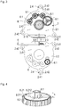
- first gears 8.1 and second gears 8.2 are provided, which are configured in the illustrated embodiment as gears, in particular spur gears.
- first gear wheels 8.1 and the second gears 8.2 according to the FIG. 4 be configured with a common axis of rotation as a one-piece body.
- the first gears 8.1 and the second gears 8.2 here each have an axial extent h of 2.0 mm.
- the second gears 8.2 have an angular pitch 8.21.
- the angular division 8.21 of each second gear 8.2 is circular.
- the angle divisions 8.21 each consist of an electrically conductive region 8.211 and a non-conductive region 8.212.
- the first gears 8.1 are as in the FIG. 3 After assembly of the first gears 8.1 and the second gears 8.2 are the respective angular divisions 8.21 the second detectors 1.23 for inductive scanning of the angular division 8.21 of the second gears 8.2 axially opposite (see the FIG. 7 ).
- the first gear closest to the later drive 8.1 is mounted on the pin 2.111 with the aid of a small roller bearing.
- the cable in particular the screen 4.1, placed in the second recess 2.12.
- the cable in particular the screen 4.1, placed in the second recess 2.12.
- the device described consisting of the printed circuit board 1, the folded metal body 2 with adhesive gap 3 and the cable 4 and the insulating material 5 is hereinafter referred to as a sensor.
- the sensor comprises a folded metal body 2, which has the first layer 2.1 with a first surface S21 and the second layer 2.2 with a second surface S22.
- the first region 1.1 of the printed circuit board 1 is glued on the first surface S21 and the second region 1.2 of the printed circuit board 1 on the second surface S22.
- the first layer 2.1 and the second layer 2.2 of the metal body 2 are arranged between the first region 1.1 and the second region 1.2 of the printed circuit board 1, so that the first region 1.1 is arranged in a first plane E11 and the second region 1.2 in a second plane E12 are. Between the first layer 2.1 and the second layer 2.2 of the metal body 2 there is an adhesive gap 3.
- the first plane E11 and the second plane E12 are arranged parallel to one another in the illustrated embodiment.
- first layer 2.1 of the metal body 2 has a third surface S23 and the second layer 2.2 of the metal body 2 has a fourth surface S24.
- the third surface S23 and the fourth surface S24 are arranged facing each other and spaced apart by the bonding gap 3.
- the first layer 2.1 of the metal body 2 the recesses 2.11 and the second layer 2.2, the recesses 2.21.
- the web 2.3 of the metal body 2 has a reduced thickness D23, it is flexible, so that the metal body 2 together with the flexible printed circuit board 1 or the web 1.3 of the printed circuit board 1 can be easily bent.
- the thickness or thickness D21 of the first layer 2.1 with 2.5 mm is exactly as large as the thickness D22 of the second layer 2.2.
- the thickness D23 of the third layer 2.3 here is 0.1 mm.
- the printed circuit board 1 or the substrate of the printed circuit board 1 here has a thickness d11 of 0.05 mm or 50 ⁇ m.
- a total thickness of the metal body 2 of about 5.05 mm, so that the metal body 2 between the first and the second region 1.1, 1.2 of the circuit board 1 has a thickness D, which is about 100 times larger than the thickness d11 of the printed circuit board 1 or of the substrate of the printed circuit board 1.
- the output-side first gears 8.1 are beyond their axial extent h within the recesses 2.11, 2.21 which are based on the axial direction between the first plane E11 and the second plane E12.
- first gear wheels 8.1 and second gear wheels 8.2 are mounted from the first surface S21 of the metal body 2 in each case in the recess 2.21 of the second layer 2.2.
- a first gear 8.1 (see, for example, the FIG. 7 ) is disposed beyond its axial extent h within the recess 2.21 of the second layer 2.2.
- this recess is 2.11 between the first plane E11 and the second plane E12, based on the axial direction, ie based on the direction of the axis of rotation A.
- a cover is mounted.
- the folded metal body 2 can now be encapsulated approximately with electrically insulating material 5, so that the electronic components 1.21 and the connection of the cable 4 are protected from external influences.
- encapsulation or potting of the electronic components 1.21 may also be carried out in an earlier production step, for example before the metal body 2 is removed from the metal panel along the contour K so as to protect the electronic components 1.21 from external influences at this stage.
- the sensor can now for example be attached to a machine part, such as a motor housing. It is particularly advantageous for this purpose the design of the metal body 2 with the fastening means 2.4 in the form of holes 2.41 in tabs 2.42, which act as a flange.
- the exactly machined contour K can at least partially serve as a stop surface, so that the fitter 2.42 with its contour K only has to bring to suitably prepared surfaces of the machine part to the stop and then rotates through holes 2.41 screws in threaded holes of the machine part. In this way, a simple and precise installation of the sensor is possible.
- FIG. 7 is a sectional image of a multi-turn encoder shown, which includes the sensor and a relatively movable (relative to the sensor rotatable) angle scale 7.1.
- the angle scale 7.1 consists of a substrate, which is made in the illustrated embodiment of epoxy resin, and on which two graduation tracks 7.11, 7.12 are arranged.
- the graduation tracks 7.11, 7.12 are circular and arranged with respect to a rotational axis A concentric with different diameters on the substrate.
- the two graduation tracks 7.11, 7.12 each consist of a periodic sequence of alternately arranged electrically conductive graduation regions and nonconductive graduation regions.
- copper was applied to the substrate in the example shown.
- the substrate was not coated in the nonconductive graduation regions.
- the angle scale 7.1 or the angle scaling usually serves as a rotor and is fastened to a machine part which is rotatable about the axis of rotation A.
- the sensor forms the stator of the multi-turn encoder, so that it is fixed to a stationary machine part.
- the angle scale 7.1 and the sensor with a comparatively small air gap face each other.
- the axis of rotation A extends through the center of the shaft 7 and the angle scaling, wherein in a relative rotation between the angular scale 7.1 and the sensor in the circuit board 1, a dependent of the respective angular position signal can be generated by induction effects.
- the multi-turn rotary encoder has the gearbox 8, which is driven by the shaft 7.
- an external toothing is incorporated in the shaft 7 in the illustrated embodiment, which meshes with a first gear 8.1.
- the angular divisions 8.21 are scanned inductively and thus determines a respective angular position of the second gears 8.2.
- the transmission 8 acts as a reduction gear, so that the rotational speeds of the gears 8.1, 8.2 are smaller than that of the shaft. 7
- the mounted on the circuit board 1 ASIC module 1.211 works not only as an evaluation, but also as a exciter control element, under whose control the excitation current, which then flows through the excitation windings 1.11, is generated.
- the exciting current voltages are induced in the first detector 1.12 as a function of the angular position of the shaft 7 or of the angle scaling, these voltages or signals being amplified, demodulated and converted into digital signals by components 1.21 mounted in the second region 1.2 of the printed circuit board 1 ,
- the position values resulting from the scanning of the individual graduation tracks are determined or calculated.
- the determination of the respective angular positions of the second gears 8.2 is carried out according to the same principle as singleturn sampling.
- the position values can be transmitted via the cable 4 to subsequent electronics, for example a numerical control of a machine.
- An angle measuring device equipped with the sensor thus serves to detect an angular position between the sensor, which can be fixed to a machine part, and the angle scale 7.1, which can be fixed to a second machine part, for example a motor shaft. In the manner described The angular position of the shaft 7 can be measured relatively accurately within a revolution.
- the metal body 2 'of the multi-turn encoder of the second embodiment differs from those of the first embodiment, inter alia, in that in the first layer 2.1' pin 2.112 '( FIG. 9 ) are provided, which serve for the storage of the integrally interconnected first gears 8.1 and the second gears 8.2 'with the angle division 8.21'. Furthermore, the second layer 2.2 'comparatively large recesses 2.21', in which the second gears 8.2 'are arranged. In the presented second embodiment, both the first gears 8.1 and the second gears 8.2 'are beyond their axial extent h within the recesses 2.11', 2.21 ', based on the axial direction between the first plane E11 and the second plane E12 are located.
- the scanning of the angular divisions 8.21 'of the second gears 8.2' takes place via a multi-turn sensor 6 'which comprises excitation windings and, as second detectors, receiver coils on a printed circuit board substrate.
- the multi-turn sensor 6 ' is placed on the second surface S22 of the metal body 2' and contacted with the required electronics before insulating material 5 'is applied by encapsulation to protect the metal body 2' and the printed circuit board 1.
Landscapes
- Physics & Mathematics (AREA)
- General Physics & Mathematics (AREA)
- Engineering & Computer Science (AREA)
- Power Engineering (AREA)
- Transmission And Conversion Of Sensor Element Output (AREA)
- Measurement Of Length, Angles, Or The Like Using Electric Or Magnetic Means (AREA)
Abstract
Description
- Multiturn-Drehgeber, häufig auch als Multiturn-Winkelmessgeräte bezeichnet, dienen zur Messung von Drehbewegungen einer Welle über mehrere Umdrehungen hinweg. In Verbindung mit Zahnstangen oder Gewindespindeln lassen sich mit Multiturn-Drehgebern auch lineare Bewegungen messen. Multiturn-Drehgeber werden insbesondere bei Werkzeugmaschinen, Industrierobotern oder Bearbeitungszentren eingesetzt.
- In derartigen Multiturn-Drehgebern werden oft durch Untersetzungsgetriebe die Drehbewegungen der zu messenden Welle auf Drehbewegungen von winkelcodierten Getrieberädern übertragen, die sich mit entsprechend geringerer Drehzahl bewegen. Auf diese Weise kann die Drehstellung der Welle über eine Vielzahl von Umdrehungen bestimmt werden. Die Drehstellungen sowohl der Welle selbst, als auch die der untersetzt angetriebenen Getrieberäder können beispielsweise mit Hilfe induktiver Sensoren bestimmt werden.
- Bei induktiven Sensoren werden häufig Erregerwindungen und Detektorwindungen in Form von Leiterbahnen auf einer gemeinsamen Leiterplatte aufgebracht, die beispielsweise mit einem Stator eines Drehgebers fest verbunden ist. Dieser Leiterplatte gegenüber befindet sich eine weitere Platine, auf der in periodischen Abständen elektrisch leitende Flächen als Teilungsstruktur aufgebracht sind und welche mit dem Rotor des Drehgebers drehfest verbunden ist. Wenn an den Erregerwindungen ein elektrisches Erregerfeld angelegt wird, werden in den Detektorwindungen während der Relativdrehung zwischen Rotor und Stator von der Winkellage abhängige Signale erzeugt. Diese Signale werden dann in einer Auswerteelektronik weiterverarbeitet.
- Bei optischen Messeinrichtungen sind häufig Lichtquellen und Fotodetektoren auf einer Leiterplatte eines optischen Sensors montiert. Mit einem Luftspalt der Leiterplatte gegenüber liegend befindet sich eine optische Skalierung. Nach bekannten Prinzipien können dann von der Position abhängige Signale erzeugt werden.
- Häufig werden derartige Multiturn-Drehgeber für elektrische Antriebe, zur Bestimmung der Relativbewegung bzw. der Relativlage von entsprechenden Maschinenteilen, eingesetzt. In diesem Fall werden die erzeugten Positionswerte einer Folgeelektronik zur Ansteuerung der Antriebe über eine entsprechende Schnittstellenanordnung zugeführt.
- In der
DE 10 2005 050 016 A1 wird ein nach dem induktiven Prinzip arbeitender Multiturn-Drehgeber beschrieben, bei welchem Zahnräder eines Getriebes an einer Leiterplatte befestigt sind. - Der Erfindung liegt die Aufgabe zugrunde einen Multiturn-Drehgeber zu schaffen, der ein gegenüber äußeren Einflüssen robustes Betriebsverhalten ermöglicht und vergleichsweise wirtschaftlich herstellbar ist.
- Diese Aufgabe wird erfindungsgemäß durch die Merkmale des Anspruches 1 gelöst.
- Der Multiturn-Drehgeber ist zur Messung einer Winkelstellung einer Welle geeignet, die um eine Achse drehbar ist. An der Welle ist drehfest eine erste Winkelskala befestigt, die von einem ersten Detektor abtastbar ist (Singleturn-Abtastung). Der Multiturn-Drehgeber weist weiterhin ein Getriebe, einen Metallkörper und eine Leiterplatte auf. Die Leiterplatte weist einen ersten Bereich auf, in dem der erste Detektor angeordnet ist und einen zweiten Bereich, in dem elektronische Bauelemente angeordnet sind, welche elektrisch mit dem ersten Detektor verbunden sind, insbesondere durch Leiterbahnen auf der Leiterplatte. Der Metallkörper ist zumindest zweilagig aufgebaut, wobei einer ersten Lage eine erste Fläche beziehungsweise Oberfläche zugeordnet werden kann und einer zweiten Lage eine zweite Fläche beziehungsweise Oberfläche. Der Metallkörper weist demnach eine erste Lage mit einer ersten Fläche sowie eine zweite Lage mit einer zweiten Fläche auf. Weiterhin weist der Metallkörper zumindest eine Ausnehmung auf. Der erste Bereich der Leiterplatte ist auf der ersten Fläche befestigt und der zweite Bereich der Leiterplatte auf der zweiten Fläche. Die erste Lage und die zweite Lage des Metallkörpers sind zwischen dem ersten Bereich der Leiterplatte und dem zweiten Bereich der Leiterplatte angeordnet, so dass der erste Bereich der Leiterplatte in einer ersten Ebene und der zweite Bereich der Leiterplatte in einer zweiten Ebene angeordnet sind. Das Getriebe ist von der Welle antreibbar, wobei dieses zumindest ein abtriebsseitiges, also letztlich von der Welle angetriebenes, Getrieberad aufweist, welches über seine axiale Ausdehnung hinweg zumindest teilweise innerhalb der Ausnehmung angeordnet ist, wobei sich die Ausnehmung bezogen auf die axiale Richtung zwischen der ersten Ebene und der zweiten Ebene befindet.
- Mit Vorteil weist die erste Lage die Ausnehmung auf. Alternativ oder ergänzend kann die zweite Lage die Ausnehmung aufweisen. Es können also auch Bauweisen vorliegen, bei denen beide Lagen eine oder mehrere Ausnehmungen aufweisen. Mit Vorteil ist die axiale Ausdehnung des ersten und / oder zweiten Getrieberades kleiner oder gleich der axialen Ausdehnung des Metallkörpers. Insbesondere kann die axiale Ausdehnung des ersten und / oder zweiten Getrieberades kleiner oder gleich der Dicke der ersten und / oder der zweiten Lage des Metallkörpers sein.
- In weiterer Ausgestaltung der Erfindung weist das Getriebe zumindest ein erstes Getrieberad und ein zweites Getrieberad auf, wobei letzteres eine Winkelteilung aufweist und das zweite Getrieberad weiterhin über seine axiale Ausdehnung hinweg zumindest teilweise innerhalb der Ausnehmung angeordnet ist.
- Vorteilhafterweise weist das Getriebe zumindest jeweils ein erstes Getrieberad und ein zweites Getrieberad auf, wobei das erste Getrieberad und das zweite Getrieberad jeweils als ein Zahnrad, insbesondere als ein Stirnrad, ausgebildet sind. Alternativ kann auch beispielsweise ein magnetisches Getriebe verwendet werden. Insbesondere kann diejenige Getriebestufe, die unmittelbar von der Welle angetrieben wird (erste Getriebestufe) ein magnetisches Getrieberad aufweisen. Weiterhin können das erste Getrieberad und das zweites Getrieberad, welches die Winkelteilung aufweist, in einem Körper in integraler Bauweise angeordnet sein.
- Gemäß einer Weiterbildung der Erfindung ist am Metallkörper in der zumindest einen Ausnehmung ein Zapfen angeformt, der zur Lagerung eines Getrieberads dient. Insbesondere ist der Zapfen als integraler Bestandteil des Metallkörpers ausgebildet und beispielsweise spanabhebend hergestellt beziehungsweise aus dem Metallkörper herausgearbeitet.
- Weiterhin kann zumindest ein zweites Getrieberad eine Winkelteilung aufweisen, wobei dann das Getriebe derart konfiguriert ist, dass bei drehender Welle die Drehzahl des zweiten Getrieberads kleiner ist als die Drehzahl der Welle.
- Der Multiturn-Drehgeber kann beispielsweise auf einem optischen Prinzip beruhen, so dass dann der erste Detektor (für die Singleturn-Abtastung) in Form eines Fotodetektors beziehungsweise Fotodetektorarrays ausgebildet sein kann. Alternativ kann der Multiturn-Drehgeber auf einem magnetischen Prinzip beruhen, wobei dann der erste Detektor für die Singleturn-Abtastung in Form eines oder mehrerer magnetoresistiven Elemente oder Hall-Elemente ausgebildet sein kann. Ebenso umfasst die Erfindung auch einen Multiturn-Drehgeber der auf einem kapazitiven Prinzip beruht. Mit Vorteil basiert der Multiturn-Drehgeber auf einem induktiven Messprinzip, wobei dann der erste Detektor für die Singleturn-Abtastung in Form von Empfängerspulen ausgebildet sein kann. In diesem Fall kann der Multiturn-Drehgeber als induktiver Multiturn-Drehgeber bezeichnet werden.
- Besonders wenn der Multiturn-Drehgeber auf einem induktiven Messprinzip beruht, ist es vorteilhaft wenn der Metallkörper aus einem ferromagnetischen, insbesondere weichmagnetischen, Stahl hergestellt ist. Alternativ kann beispielsweise auch Aluminium als Material für den Metallkörper verwendet werden.
- Mit Vorteil sind bei einem Multiturn-Drehgeber, der auf einem induktiven Messprinzip beruht, im ersten Bereich der Leiterplatte Erregerwindungen angeordnet. Insbesondere können dann im zweiten Bereich elektronische Bauelemente angeordnet sein, welche elektrisch mit den Erregerwindungen verbunden sind, so dass die von den betreffenden Bauelementen erzeugten Erregerströme in die Erregerwindungen übertragen werden können.
- In weiterer Ausgestaltung der Erfindung ist der Metallkörper einstückig ausgestaltet und weist einen flexiblen Steg auf, der gebogen verläuft und die erste Lage mit der zweiten Lage verbindet.
- Vorteilhafterweise ist die Leiterplatte flexibel und einstückig ausgestaltet, wobei die Leiterplatte zudem einen gebogenen Verbindungssteg zwischen dem ersten Bereich und dem zweiten Bereich aufweist. Mit Vorteil ist die Leiterplatte mehrschichtig aufgebaut. Besonders vorteilhaft ist es, wenn die Leiterplatte Polyimid- oder Epoxy-Material umfasst. In vorteilhafter Ausgestaltung der Erfindung weist die Leiterplatte eine Dicke von weniger als 200 µm, insbesondere weniger als 120 µm auf, wobei hier insbesondere auf die Dicke des Substrats der Leiterplatte Bezug genommen wird und keinesfalls auf die Höhe der auf der Leiterplatte montierten Bauelemente.
- Mit Vorteil weist zumindest ein zweites Getrieberad eine Winkelteilung auf, so dass dessen Winkelstellung durch einen zweiten Detektor (Multiturn-Abtastung), welcher auf einem induktiven Messprinzip basiert, bestimmbar ist. Die Abtastung der jeweiligen Winkelteilung kann jeweils mit einem zweiten Detektor vorgenommen, welcher nach den im Zusammenhang mit der Singleturn-Abtastung beschriebenen Prinzipien, insbesondere alternativ zum induktiven Abtastprinzip nach einem magnetischen Prinzip, erfolgen kann.
- In weiterer Ausgestaltung der Erfindung weist der Metallkörper eine Dicke von mehr als 0,5 mm, insbesondere von mehr als 1,0 mm, mit Vorteil mehr als 1,5 mm auf.
- Insbesondere weist die erste Lage des Metallkörpers eine dritte Fläche beziehungsweise Oberfläche auf und die zweite Lage des Metallkörpers weist eine vierte Fläche beziehungsweise Oberfläche auf. Die dritte Fläche und die vierte Fläche sind einander zugewandt angeordnet. Insbesondere sind die erste Fläche und die dritte Fläche der ersten Lage des Metallkörpers gegenüberliegend zueinander angeordnet. Ebenso sind die zweite Fläche und die vierte Fläche, die jeweils der zweiten Lage des Metallkörpers zugeordnet sind, gegenüberliegend zueinander angeordnet.
- Vorteilhafterweise sind die erste Fläche, die zweite Fläche, die dritte Fläche, und die vierte Fläche des Metallkörpers beziehungsweise der Lagen des Metallkörpers parallel zueinander angeordnet.
- Mit Vorteil weist der Metallkörper weiterhin Befestigungsmittel zur mechanischen Befestigung des Multiturn-Drehgebers an einem Maschinenteil auf. Gemäß einer weiteren Ausgestaltung ist das Befestigungsmittel als eine Bohrung durch die erste Lage und / oder die zweite Lage des Metallkörpers ausgestaltet. Insbesondere kann der Metallkörper also nicht nur Träger der Leiterplatte sein, sondern gleichzeitig auch eine Flanschfunktion erfüllen. Beispielsweise können auskragende Laschen mit Bohrungen vorgesehen sein, die zur Befestigung des Multiturn-Drehgebers an einem Maschinenteil dienen.
- In weiterer Ausgestaltung der Erfindung ist zwischen der ersten Lage und der zweiten Lage des Metallkörpers ein Klebespalt angeordnet, also ein Spalt, der mit Klebstoff ausgefüllt ist. Sofern ein Klebespalt vorliegt, sind insbesondere die dritte Fläche und die vierte Fläche durch den Klebespalt voneinander beabstandet. Der Klebespalt ist also insbesondere zwischen der dritten Fläche und der vierten Fläche angeordnet.
- Die Lagen des Metallkörpers sind folglich durch eine Klebefügung stoffschlüssig miteinander verbunden. Alternativ können die Lagen des Metallkörpers miteinander verlötet sein, so dass insbesondere zwischen der ersten Lage und der zweiten Lage des Metallkörpers ein Lotmaterial angeordnet ist. Alternativ können die Lagen des Metallkörpers auch miteinander verschweißt sein.
- Die Erfindung umfasst aber auch eine alternative Bauweise, bei der kein Klebespalt zwischen der ersten Lage und der zweiten Lage des Metallkörpers vorliegt und bei der die Lagen des Metallkörpers durch eine Umspritzung insbesondere mit einem Kunststoff oder mit einem Silikonwerkstoff zusammengehalten werden. Bei dieser Bauweise kann also der Metallkörper durch Faltung zusammen mit der Leiterplatte hergestellt werden und in diesem Zustand umspritzt werden.
- Zwischen der ersten Lage und der zweiten Lage des Metallkörpers kann eine thermisch isolierende Schicht vorgesehen sein. Insbesondere bei dieser Bauweise kann nur die erste Lage oder nur die zweite Lage das Befestigungsmittel aufweisen. Wenn beispielsweise Komponenten im ersten Bereich der Leiterplatte relativ temperaturunempfindlich sind, kann die erste Lage an einem vergleichsweise heißem Bauteil befestigt werden, wobei ein Wärmefluss zur zweiten Lage und damit auf möglicherweise temperaturempfindlichere Bauelemente auf dem zweiten Bereich der Leiterplatte durch die isolierende Schicht behindert werden kann.
- Weiterhin kann der Metallkörper so ausgestaltet sein, dass dieser eine Kontur aufweist, die mechanisch bearbeitet ist und die als Referenz beziehungsweise Anschlag zum passgenauen Anbau an ein Maschinenteil verwendbar ist.
- Mit Vorteil umfasst der Multiturn-Drehgeber ein Kabel mit einem Schirm, der elektrisch leitend mit dem Metallkörper verbunden ist. Somit kann der Metallkörper auch eine Masseanbindung des Multiturn-Drehgebers ermöglichen.
- Mit Vorteil weist der Abschnitt des Metallkörpers, welcher zwischen dem ersten und dem zweiten Bereich der Leiterplatte angeordnet ist, eine Dicke von mehr als 0,5 mm, insbesondere mehr als 1,0 mm oder mehr als 1,5 mm auf.
- Mit anderen Worten ist insbesondere der Abstand zwischen dem ersten Bereich der Leiterplatte und dem zweiten Bereich der Leiterplatte gleich der Dicke des Metallkörpers in dem genannten Abschnitt. Weiterhin kann der Metallkörper so aufgebaut sein, dass die erste Lage und die zweite Lage jeweils die gleiche Dicke beziehungsweise Stärke aufweisen. Vorteilhafterweise weist der Metallkörper zwischen dem ersten und dem zweiten Bereich der Leiterplatte eine Dicke auf, welche mindestens 5 mal, insbesondere mindestens 10 mal oder mindestens 15 mal, größer ist als die Dicke der Leiterplatte beziehungsweise des Substrats der Leiterplatte. Der Metallkörper ist als starrer Körper ausgebildet und bildet einen mechanischen Träger für die dünne flexible Leiterplatte und die Getriebräder. Daher umfasst der Begriff Metallkörper im Folgenden keine flexible Metallfolie.
- Durch die besondere Bauweise des Multiturn-Drehgebers ist ein Herstellungsverfahren anwendbar, bei dem zunächst eine Metalltafel mit dem Substrat einer flexiblen insbesondere mehrschichtigen Leiterplatte beschichtet beziehungsweise beklebt wird, so dass auf diese Weise die Leiterplatte auf der Oberfläche der Metalltafel befestigt ist. Mit Vorteil kann der Schichtaufbau der Leiterplatte auf der Metalltafel vorgenommen werden, so dass also keine vorgefertigten Leiterplatten mit Substrat und Leiterstrukturen verwendet werden. Vielmehr werden bei dieser Variante die erforderlichen (beispielsweise fotochemischen) Prozessschritte zum Aufbau der insbesondere mehrschichtigen Leiterplatte auf der Metalltafel vorgenommen.
- Danach können einzelne Metallteile zusammen mit den Leiterplatten beziehungsweise dem Substrat abgetrennt werden. Nach einer Faltung und gegebenenfalls einer Klebung ist der Metallkörper hergestellt. Die elektronischen Bauelemente können beispielsweise vor der Faltung auf der Leiterplatte montiert werden und / oder nach der Faltung. Das Substrat der Leiterplatte kann als Bogen auf die Metalltafel aufgebracht werden und kann zusammen mit der Metalltafel abgetrennt beziehungsweise vereinzelt werden. Alternativ können auch einzelne Leiterplatten auf der Metalltafel befestigt beziehungsweise aufgeklebt werden, so dass die Metalltafel um diese herum geschnitten beziehungsweise abgetrennt wird.
- Vorteilhafte Ausbildungen der Erfindung entnimmt man den abhängigen Ansprüchen.
- Weitere Einzelheiten und Vorteile des erfindungsgemäßen Multiturn-Drehgebers ergeben sich aus der nachfolgenden Beschreibung von Ausführungsbeispielen anhand der beiliegenden Figuren.
- Es zeigen die
- Figur 1
- eine Draufsicht auf eine erste Seite eines Multiturn-Drehgeber-Bauteils in einer frühen Montagephase,
- Figur 2
- eine Draufsicht auf eine zweite Seite des Multiturn-Drehgeber-Bauteils in einer frühen Montagephase,
- Figur 3
- eine Draufsicht auf die zweite Seite des Multiturn-Drehgeber-Bauteils in einer darauffolgenden Montagephase,
- Figur 4
- eine perspektivische Ansicht auf ein erstes und zweites Getrieberad,
- Figur 5
- eine Draufsicht auf die erste Seite des Multiturn-Drehgeber-Bauteils in einer darauffolgenden Montagephase,
- Figur 6
- Teilschnittdarstellung durch einen Sensor des Multiturn-Dreh-gebers,
- Figur 7
- eine Schnittdarstellung des Multiturn-Drehgebers,
- Figur 8
- eine perspektivische Ansicht auf ein erstes und zweites Getrieberad gemäß einem zweiten Ausführungsbeispiel,
- Figur 9
- eine Schnittdarstellung des Multiturn-Drehgebers gemäß dem zweiten Ausführungsbeispiel.
- Im Zuge der Herstellung eines Multiturn-Drehgebers gemäß dem vorliegenden Ausführungsbeispiel wird zunächst eine Metalltafel, die hier eine Stärke beziehungsweise Dicke von 2,5 mm aufweist und aus weichmagnetischem Stahl (hier ein ferritischer Edelstahl) hergestellt ist, bereitgestellt. Auf dieser Metalltafel wird eine Vielzahl von flexiblen mehrschichtigen Leiterplatten 1 nach einem vorgegebenen Muster befestigt, insbesondere aufgeklebt. Jede der Leiterplatten 1 weist ein vergleichsweise dünnes Substrat (hier 0,1 mm) beispielsweise aus Polyimid auf, so dass die Leiterplatten 1 an sich flexibel sind.
- Alternativ können die Leiterplatten 1 auch durch unmittelbaren Schichtaufbau auf der Metalltafel erzeugt werden.
- In der
Figur 1 ist eine mehrschichtig aufgebaute flexible Leiterplatte 1 zu sehen. Diese ist einstückig und weist einen ersten Bereich 1.1 auf, der in erster Näherung ringförmig ausgestaltet ist. Weiterhin weist die Leiterplatte 1 einen zweiten Bereich 1.2 auf. Zwischen dem ersten Bereich 1.1 und dem zweiten Bereich 1.2 weist die Leiterplatte 1 einen dritten Bereich 1.3 auf, der als Steg ausgestaltet ist und eine Verbindung zwischen dem ersten Bereich 1.1 und dem zweiten Bereich 1.2 darstellt. - Im Fertigungszustand gemäß der
Figur 1 ist das Leiterbild der Leiterplatte 1 erkennbar. Demnach sind im ersten Bereich 1.1 so genannte Erregerwindungen 1.11 und ein erster Detektor 1.12 in Form von Empfängerspulen vorgesehen, die als Leiterbahnen auf dem dünnen Substrat ausgebildet sind. Im vorgestellten Ausführungsbeispiel sind dem ersten Detektor 1.12 beziehungsweise den Empfängerspulen zwei Spuren zugeordnet. - Im zweiten Bereich 1.2 der Leiterplatte 1 sind Leiterbahnen und Pads dargestellt. Im zweiten Bereich 1.2 sind außerdem drei Multiturnsensoren angeordnet, die ebenfalls jeweils einen zweiten Detektor 1.22 in Form von Empfängerspulen und Erregerwindungen 1.23 aufweisen. Die zweiten Detektoren 1.22 und die Erregerwindungen 1.23 sind als Leiterbahnen auf dem dünnen Substrat ausgebildet.
- Im dritten Bereich 1.3 der Leiterplatte 1 sind in den Figuren nicht dargestellte Leiterbahnen aufgebracht, die zur elektrischen Verbindung der Komponenten im ersten Bereich 1.1 und denen im zweiten Bereich 1.2 der Leiterplatte 1 dienen.
- Im Zuge der Herstellung des Multiturn-Drehgebers können nun auf dem zweiten Bereich 1.2 elektronische Bauelemente 1.21 montiert werden, zu denen im vorgestellten Ausführungsbeispiel auch ein ASIC-Baustein 1.211 gehört.
- Nachdem die Vielzahl von flexiblen Leiterplatten 1 nach einem vorgegebenen Muster auf die Metalltafel aufgeklebt worden sind, wird die Metalltafel in einem darauffolgenden Herstellungsschritt mechanisch bearbeitet. Insbesondere wird die der flexiblen Leiterplatten 1 gegenüber liegende Seite, wie sie beispielsweise in der
Figur 2 dargestellt ist, bearbeitet. In diesem Zusammenhang werden zunächst in die Metalltafel mehrere Ausnehmungen 2.11, 2.21; 2.11', 2.21' eingearbeitet, insbesondere mit einem Fräsprozess. Eine der Ausnehmungen 2.11 wird derart vorgenommen, dass ein zentraler Zapfen 2.111 stehen bleibt. Weiterhin wird ein Steg 2.3 hergestellt, indem an der betreffenden Stelle Material aus der Metalltafel entfernt wird. Demnach wird der Steg 2.3 des Metallkörpers 2 derart bearbeitet, dass dieser zumindest stellenweise eine reduzierte Dicke D23 (Figur 6 ) aufweist. Folglich ist der Metallkörper 2 im vorgestellten Ausführungsbeispiel einteilig ausgestaltet, wobei der Steg 2.3 des Metallkörpers 2 unter dem dritten Bereich 1.3 der Leiterplatte 1 angeordnet ist beziehungsweise bezüglich der Faltachse radial innen liegend. - Weiterhin werden Befestigungsmittel 2.4 in Form von Bohrungen 2.41 in Laschen 2.42 hergestellt sowie zwei zweite Ausnehmungen 2.12, 2.22. Schließlich wird aus der Metalltafel ein Metallkörper 2 entlang der Kontur K herausgetrennt, beispielsweise durch einen Fräsprozess oder einen Laser- oder Wasserstrahlschneidprozess.
- Danach werden erste Getrieberäder 8.1 und zweite Getrieberäder 8.2 bereitgestellt, die im vorgestellten Ausführungsbeispiel als Zahnräder, insbesondere Stirnräder, ausgestaltet sind. Häufig können zudem die ersten Getrieberäder 8.1 und die zweiten Getrieberäder 8.2 gemäß der
Figur 4 mit einer gemeinsamen Rotationsachse als ein einstückiger Körper ausgestaltet sein. Die ersten Getrieberäder 8.1 und die zweiten Getrieberäder 8.2 haben hier jeweils eine axiale Ausdehnung h von 2,0 mm. Die zweiten Getrieberäder 8.2 weisen eine Winkelteilung 8.21 auf. Die Winkelteilung 8.21 eines jeden zweiten Getrieberades 8.2 ist kreisförmig ausgebildet. Die Winkelteilungen 8.21 bestehen jeweils aus einem elektrisch leitfähigen Bereich 8.211 und einem nichtleitfähigen Bereich 8.212. Als Material für die elektrisch leitfähigen Teilungsbereiche 8.211 wurde im gezeigten Beispiel Kupfer auf die zweiten Getrieberäder 8.2 aufgebracht. In den nichtleitfähigen Bereichen 8.212 sind die zweiten Getrieberäder 8.2 dagegen nicht beschichtet. - Die ersten Getrieberäder 8.1 werden wie in der
Figur 3 dargestellt in die Ausnehmungen 2.11, 2.21 montiert und gehören zu einem Getriebe 8. Nach erfolgter Montage der ersten Getrieberäder 8.1 und der zweiten Getrieberäder 8.2 liegen die jeweiligen Winkelteilungen 8.21 den zweiten Detektoren 1.23 zur induktiven Abtastung der Winkelteilung 8.21 der zweiten Getrieberäder 8.2 axial gegenüber (siehe dieFigur 7 ). Das dem späteren Antrieb am nächsten liegende erste Getrieberad 8.1 wird mit Hilfe eines kleinen Wälzlagers am Zapfen 2.111 montiert. - Im weiteren Fortgang des Herstellungsprozesses wird das Kabel, insbesondere der Schirm 4.1, in die zweite Ausnehmung 2.12 gelegt. Somit ist nicht nur eine mechanische Verbindung zwischen dem Metallkörper 2 und dem Kabel 4 hergestellt, sondern auch eine elektrische Verbindung zwischen dem Metallkörper 2 und dem Schirm 4.1.
- Danach wird auf die in der
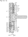
Figur 3 sichtbare Seite des Metallkörpers 2 partiell ein Kleber aufgetragen und die Leiterplatte 1 und der Metallkörper 2 mit den ersten Getrieberädern 8.1 werden gemeinsam so gefaltet, dass jeweils ein Paar der Bohrungen 2.41 einer ersten Lage 2.1 und einer zweiten Lage 2.2 des Metallkörpers 2 übereinander zu liegen kommen (sieheFigur 5 ). Um die relative Ausrichtung der beiden Lagen 2.1, 2.2 bei Bedarf exakter zu positionieren können beispielsweise Passstifte in die Bohrungen 2.41 eingeführt werden. Alternativ oder ergänzend können auch direkt am Metallkörper 2 Passstifte oder Passnasen vorgesehen sein, die in entsprechende Passöffnungen der jeweiligen anderen Lage nach dem Falten oder während des Faltens eingreifen. - Die beschriebene Vorrichtung bestehend aus der Leiterplatte 1, dem gefalteten Metallkörper 2 mit Klebspalt 3 und dem Kabel 4 sowie dem isolierenden Material 5 wird im Folgenden als Sensor bezeichnet. In der
Figur 6 ist ein Teilschnitt durch den Sensor im Bereich des Stegs 2.3 des Metallkörpers 2 (entlang der Linie B - B inFigur 5 ) dargestellt. Demnach umfasst der Sensor einen gefalteten Metallkörper 2, der die erste Lage 2.1 mit einer ersten Fläche S21 sowie die zweite Lage 2.2 mit einer zweiten Fläche S22 aufweist. Der erste Bereich 1.1 der Leiterplatte 1 ist auf der ersten Fläche S21 und der zweite Bereich 1.2 der Leiterplatte 1 auf der zweiten Fläche S22 aufgeklebt. Die erste Lage 2.1 und die zweite Lage 2.2 des Metallkörpers 2 sind zwischen dem ersten Bereich 1.1 und dem zweiten Bereich 1.2 der Leiterplatte 1 angeordnet, so dass der erste Bereich 1.1 in einer ersten Ebene E11 und der zweite Bereich 1.2 in einer zweiten Ebene E12 angeordnet sind. Zwischen der ersten Lage 2.1 und die zweiten Lage 2.2 des Metallkörpers 2 befindet sich ein Klebespalt 3. Die erste Ebene E11 und die zweite Ebene E12 sind im vorgestellten Ausführungsbeispiel parallel zueinander angeordnet. - Außerdem weist die erste Lage 2.1 des Metallkörpers 2 eine dritte Fläche S23 auf und die zweite Lage 2.2 des Metallkörpers 2 weist eine vierte Fläche S24 auf. Die dritte Fläche S23 und die vierte Fläche S24 sind einander zugewandt angeordnet und durch den Klebespalt 3 voneinander beabstandet.
- Weiterhin weist die erste Lage 2.1 des Metallkörpers 2 die Ausnehmungen 2.11 auf und die zweite Lage 2.2 die Ausnehmungen 2.21.
- Dadurch, dass der Steg 2.3 des Metallkörpers 2 eine reduzierte Stärke D23 aufweist ist dieser flexibel, so dass der Metallkörper 2 zusammen mit der flexiblen Leiterplatte 1 beziehungsweise dem Steg 1.3 der Leiterplatte 1 problemlos gebogen werden kann. Im vorgestellten Ausführungsbeispiel ist die Stärke beziehungsweise Dicke D21 der ersten Lage 2.1 mit 2,5 mm genau so groß wie die Dicke D22 der zweiten Lage 2.2. Die Dicke D23 der dritten Lage 2.3 beträgt hier 0,1 mm. Die Leiterplatte 1 beziehungsweise das Substrat der Leiterplatte 1 weist hier eine Dicke d11 von 0,05 mm oder 50 µm auf. Nachdem der Klebespalt 3 etwa 0,05 mm dick ist, ergibt sich eine Gesamtdicke des Metallkörpers 2 von etwa 5,05 mm, so dass also der Metallkörper 2 zwischen dem ersten und dem zweiten Bereich 1.1, 1.2 der Leiterplatte 1 eine Dicke D aufweist, welche etwa 100 mal größer ist als die Dicke d11 der Leiterplatte 1 beziehungsweise des Substrats der Leiterplatte 1.
- Nach dem oben beschriebenen Falten befinden sich die abtriebsseitigen ersten Getrieberäder 8.1 über ihre axiale Ausdehnung h hinweg innerhalb der Ausnehmungen 2.11, 2.21 die sich bezogen auf die axiale Richtung zwischen der ersten Ebene E11 und der zweiten Ebene E12 befinden.
- Nach diesem Herstellungsschritt werden die Körper, welche als integralen Bestandteil erste Getrieberäder 8.1 und zweite Getrieberäder 8.2 aufweisen (Figur 4) von der der ersten Fläche S21 des Metallkörpers 2 her jeweils in der Ausnehmung 2.21 der zweiten Lage 2.2 montiert. Im Ergebnis ist dann ein erstes Getrieberad 8.1 (siehe etwa die
Figur 7 ) über seine axiale Ausdehnung h hinweg innerhalb der Ausnehmung 2.21 der zweiten Lage 2.2 angeordnet. Dabei befindet sich diese Ausnehmung 2.11 zwischen der ersten Ebene E11 und der zweiten Ebene E12, bezogen auf die axiale Richtung, also bezogen auf die Richtung der Drehachse A. Über den zweiten Getrieberädern 8.2 wird jeweils ein Deckel 8.5 montiert. - Der gefaltete Metallkörper 2 kann nun etwa mit elektrisch isolierendem Material 5 umspritzt werden, so dass die elektronischen Bauelemente 1.21 sowie der Anschluss des Kabels 4 vor äußeren Einflüssen geschützt sind.
- Alternativ kann ein Umspritzen beziehungsweise ein Vergießen der elektronischen Bauelemente 1.21 auch schon in einem früheren Herstellungsschritt vorgenommen werden, etwa vor dem Heraustrennen des Metallkörpers 2 aus der Metalltafel entlang der Kontur K um so die elektronischen Bauelemente 1.21 in diesem Stadium vor äußeren Einflüssen zu schützen.
- Der Sensor kann nun beispielsweise an einem Maschinenteil, etwa an einem Motorgehäuse, befestigt werden. Besonders vorteilhaft ist für diesen Zweck die Ausgestaltung des Metallkörpers 2 mit den Befestigungsmitteln 2.4 in Form von Bohrungen 2.41 in Laschen 2.42, die als Flansch wirken. Zudem kann die exakt bearbeitete Kontur K zumindest bereichsweise als Anschlagfläche dienen, so dass der Monteur des Sensors die Laschen 2.42 mit ihrer Kontur K lediglich an entsprechend vorbereiteten Flächen des Maschinenteils zum Anschlag bringen muss und anschließend durch die Bohrungen 2.41 Schrauben in Gewindebohrungen des Maschinenteil dreht. Auf diese Weise ist eine einfache und präzise Montage des Sensors möglich.
- In der
Figur 7 ist ein Schnitt-Bild eines Multiturn-Drehgebers dargestellt, welcher den Sensor und eine relativ dazu bewegbare (hier relativ zum Sensor drehbare) Winkelskala 7.1 umfasst. Die Winkelskala 7.1 besteht aus einem Substrat, welches im dargestellten Ausführungsbeispiel aus Epoxydharz hergestellt ist, und auf welchem zwei Teilungsspuren 7.11, 7.12 angeordnet sind. Die Teilungsspuren 7.11, 7.12 sind kreisförmig ausgebildet und bezüglich einer Drehachse A konzentrisch mit unterschiedlichen Durchmessern auf dem Substrat angeordnet. Die beiden Teilungsspuren 7.11, 7.12 bestehen jeweils aus einer periodischen Abfolge von alternierend angeordneten elektrisch leitfähigen Teilungsbereichen und nichtleitfähigen Teilungsbereichen. Als Material für die elektrisch leitfähigen Teilungsbereiche wurde im gezeigten Beispiel Kupfer auf das Substrat aufgebracht. In den nichtleitfähigen Teilungsbereichen wurde das Substrat dagegen nicht beschichtet. - Üblicherweise dient die Winkelskala 7.1 beziehungsweise die Winkelskalierung als Rotor und wird an einem um die Drehachse A drehbaren Maschinenteil befestigt. Dagegen bildet dann der Sensor den Stator des Multiturn-Drehgebers, so dass dieser an einem stehenden Maschinenteil fixiert wird. Im zusammengebauten Zustand des Multiturn-Drehgebers stehen sich die Winkelskala 7.1 und der Sensor mit vergleichsweise geringem Luftspalt einander gegenüber. Die Drehachse A verläuft durch das Zentrum der Welle 7 beziehungsweise der Winkelskalierung, wobei bei einer Relativdrehung zwischen dem Winkelskala 7.1 und dem Sensor in der Leiterplatte 1 ein von der jeweiligen Winkelstellung abhängiges Signal durch Induktionseffekte erzeugbar ist.
- Damit die Winkelstellung über mehrere Umdrehungen hinweg erfasst werden kann weist der Multiturn-Drehgeber das Getriebe 8 auf, das von der Welle 7 angetrieben wird. Zu diesem Zweck ist in die Welle 7 im vorgestellten Ausführungsbeispiel eine Außenverzahnung eingearbeitet, die mit einem ersten Getrieberad 8.1 kämmt. Dieses leitet die Drehbewegung untersetzt letztendlich an die zweiten Getrieberäder 8.2 weiter, die eine Winkelteilung 8.21 aufweisen. Im vorgestellten Ausführungsbeispiel werden die Winkelteilungen 8.21 induktiv gescannt und so eine jeweilige Winkelstellung der zweiten Getrieberäder 8.2 bestimmt. Durch die Ermittlung der Winkelstellung der zweiten Getrieberäder 8.2 des Getriebes 8 kann dann die Winkelstellung der Welle 7 über viele Umdrehungen hinweg bestimmt werden. Dabei wirkt das Getriebe 8 als Untersetzungsgetriebe, so dass die Drehzahlen der Getrieberäder 8.1, 8.2 kleiner sind als die der Welle 7.
- Der auf der Leiterplatte 1 montierte ASIC-Baustein 1.211 arbeitet nicht nur als Auswerteelement, sondern auch als Erregerkontrollelement, unter dessen Kontrolle der Erregerstrom, welcher dann durch die Erregerwindungen 1.11 fließt, erzeugt wird. Durch den Erregerstrom werden im ersten Detektor 1.12 Spannungen in Abhängigkeit von der Winkelstellung der Welle 7 beziehungsweise der Winkelskalierung induziert, wobei diese Spannungen beziehungsweise Signale durch Bauelemente 1.21, die im zweiten Bereich 1.2 der Leiterplatte 1 montiert sind verstärkt, demoduliert und in digitale Signale gewandelt werden. In logischen Schaltungen auf dem Digitalteil des ASIC-Bausteins 1.211 werden die Positionswerte resultierend aus der Abtastung der einzelnen Teilungsspuren ermittelt beziehungsweise berechnet. Die Ermittlung der jeweiligen Winkelstellungen der zweiten Getrieberäder 8.2 wird nach analogen Prinzip wie die Singleturn-Abtastung vorgenommen.
- Die Positionswerte können über das Kabel 4 an eine Folgeelektronik, beispielsweise eine Numerische Steuerung einer Maschine, übertragen werden. Eine mit dem Sensor ausgestattete Winkelmesseinrichtung dient demnach zur Erfassung einer Winkelposition zwischen dem Sensor, der an einem Maschinenteil festlegbar ist und der Winkelskala 7.1, die an einem zweiten Maschinenteil, etwa einer Motorwelle, festlegbar ist. Auf die beschriebene Weise kann die Winkelstellung der Welle 7 innerhalb einer Umdrehung vergleichsweise genau gemessen werden.
- Anhand der
Figuren 8 und 9 wird eine alternative Ausgestaltung des Sensors beschrieben. Bei dieser Variante werden im Vergleich zum ersten Ausführungsbeispiel anders gestaltete zweite Getrieberäder 8.2' verwendet, wie in derFigur 8 dargestellt. Diese zweiten Getrieberäder 8.2' weisen jeweils auf derjenigen Seite, die den ersten Getrieberädern 8.1 abgewandt ist, eine Winkelteilung 8.21' auf. Diese besteht wie im ersten Ausführungsbeispiel jeweils aus einem elektrisch leitfähigen Bereich 8.211' und einem nichtleitfähigen Bereich 8.212'. - Der Metallkörper 2' des Multiturn-Drehgebers des zweiten Ausführungsbeispiels unterscheidet sich von denjenigen des ersten Ausführungsbeispiels unter anderem dadurch, dass in der ersten Lage 2.1' Zapfen 2.112' (
Figur 9 ) vorgesehen sind, die zur Lagerung der einstückig miteinander verbundenen ersten Getrieberäder 8.1 und der zweiten Getrieberäder 8.2' mit der Winkelteilung 8.21' dienen. Weiterhin weist die zweite Lage 2.2' vergleichsweise große Ausnehmungen 2.21' auf, in welchen die zweiten Getrieberäder 8.2' angeordnet sind. Im vorgestellten zweiten Ausführungsbeispiel befinden sich sowohl die ersten Getrieberäder 8.1 als auch die zweiten Getrieberäder 8.2' über ihre axiale Ausdehnung h hinweg innerhalb der Ausnehmungen 2.11', 2.21', die sich bezogen auf die axiale Richtung zwischen der ersten Ebene E11 und der zweiten Ebene E12 befinden. - Die Abtastung der Winkelteilungen 8.21' der zweiten Getrieberäder 8.2' erfolgt über einen Multiturnsensor 6', der Erregerwindungen und als zweite Detektoren Empfängerspulen auf einem Leiterplattensubstrat umfasst. Der Multiturnsensor 6' wird auf die zweite Fläche S22 des Metallkörpers 2' platziert und mit der erforderlichen Elektronik kontaktiert bevor isolierendes Material 5' mittels Umspritzung zum Schutz des Metallkörpers 2' und der Leiterplatte 1 aufgebracht wird.
Claims (15)
- Multiturn-Drehgeber zur Messung einer Winkelstellung einer Welle (1), die um eine Achse (A) drehbar ist, wobei an der Welle (7) drehfest eine erste Winkelskala (7.1) befestigt ist, die von einem ersten Detektor (1.12) abtastbar ist, wobei der Multiturn-Drehgeber weiterhin ein Getriebe (8), einen Metallkörper (2; 2') und eine Leiterplatte (1) aufweist, und
die Leiterplatte (1) einen ersten Bereich (1.1) aufweist, in dem der erste Detektor (1.12) angeordnet ist und einen zweiten Bereich (1.2) aufweist, in dem elektronische Bauelemente (1.21) angeordnet sind, welche elektrisch mit dem ersten Detektor (1.12) verbunden sind,
der Metallkörper (2; 2') zumindest eine Ausnehmung (2.11, 2.21; 2.11', 2.21'), eine erste Lage (2.1) mit einer ersten Fläche (S21) sowie eine zweite Lage (2.2, 2.2') mit einer zweiten Fläche (S22) aufweist,
der erste Bereich (1.1) der Leiterplatte (1) auf der ersten Fläche (S21) befestigt ist und der zweite Bereich (1.2) der Leiterplatte (1) auf der zweiten Fläche (S22) befestigt ist, so dass der erste Bereich (1.1) in einer ersten Ebene (E11) und der zweite Bereich (1.2) in einer zweiten Ebene (E12) angeordnet sind und
das Getriebe (8) von der Welle (7) antreibbar ist, wobei dieses zumindest ein abtriebsseitiges Getrieberad (8.1, 8.2; 8.2') aufweist, welches über seine axiale Ausdehnung (h) hinweg zumindest teilweise innerhalb der Ausnehmung (2.11, 2.21; 2.11', 2.21') angeordnet ist, wobei sich die Ausnehmung (2.11, 2.21; 2.11', 2.21') bezogen auf die axiale Richtung zwischen der ersten Ebene (E11) und der zweiten Ebene (E12) befindet. - Multiturn-Drehgeber gemäß dem Anspruch 1, wobei die erste Lage (2.1) die Ausnehmung (2.11) und / oder die zweite Lage (2.2) die Ausnehmung (2.21) aufweist.
- Multiturn-Drehgeber gemäß einem der vorhergehenden Ansprüche, wobei das Getriebe (8) zumindest ein erstes Getrieberad (8.1) und ein zweites Getrieberad (8.2; 8.2') aufweist, wobei das zweite Getrieberad (8.2; 8.2') eine Winkelteilung (8.21; 8.21') aufweist und das zweite Getrieberad (8.2; 8.2') über seine axiale Ausdehnung (h) hinweg zumindest teilweise innerhalb der Ausnehmung (2.11, 2.21; 2.11', 2.21') angeordnet ist.
- Multiturn-Drehgeber gemäß einem der vorhergehenden Ansprüche, wobei das Getriebe (8) zumindest jeweils ein erstes Getrieberad (8.1) und ein zweites Getrieberad (8.2; 8.2') aufweist, wobei das erste Getrieberad (8.1) und das zweite Getrieberad (8.2; 8.2') jeweils als ein Zahnrad, insbesondere als ein Stirnrad, ausgebildet sind.
- Multiturn-Drehgeber gemäß einem der vorhergehenden Ansprüche, wobei am Metallkörper (2; 2') in der zumindest einen Ausnehmung (2.11, 2.21; 2.11', 2.21') ein Zapfen (2.111; 2.112') angeformt ist, der zur Lagerung eines Getrieberads (8.1, 8.2; 8.2') dient.
- Multiturn-Drehgeber gemäß einem der vorhergehenden Ansprüche, wobei der Multiturn-Drehgeber auf einem induktiven Messprinzip basiert und der erste Detektor (1.12) in Form von Empfängerspulen ausgebildet ist.
- Multiturn-Drehgeber gemäß einem der vorhergehenden Ansprüche, wobei der Metallkörper (2; 2') aus weichmagnetischem Stahl hergestellt ist.
- Multiturn-Drehgeber gemäß einem der Ansprüche 6 oder 7, wobei im ersten Bereich (1.1) der Leiterplatte (1) Erregerwindungen (1.11) angeordnet sind.
- Multiturn-Drehgeber gemäß dem Anspruch 8, wobei im zweiten Bereich (1.2) elektronische Bauelemente (1.21) angeordnet sind, welche elektrisch mit den Erregerwindungen (1.11) verbunden sind.
- Multiturn-Drehgeber gemäß einem der vorhergehenden Ansprüche, wobei die Leiterplatte (1) flexibel und einstückig ausgestaltet ist und einen gebogenen Verbindungssteg (1.3) zwischen dem ersten Bereich (1.1) und dem zweiten Bereich (1.2) aufweist.
- Multiturn-Drehgeber gemäß einem der vorhergehenden Ansprüche, wobei zumindest ein zweites Getrieberad (8.2; 8.2') eine Winkelteilung (8.21; 8.21') aufweist, so dass dessen Winkelstellung durch einen zweiten Detektor, welcher auf einem induktiven Messprinzip basiert, bestimmbar ist.
- Multiturn-Drehgeber gemäß einem der vorhergehenden Ansprüche, wobei der Metallkörper eine Dicke von mehr als 0,5 mm aufweist.
- Multiturn-Drehgeber gemäß einem der vorhergehenden Ansprüche, wobei die erste Lage (2.1) des Metallkörpers (2; 2') eine dritte Fläche (S23) aufweist und die zweite Lage (2.2, 2.2') des Metallkörpers (2; 2') eine vierte Fläche (S24) aufweist, wobei die dritte Fläche (S23) und die vierte Fläche (S24) einander zugewandt angeordnet sind.
- Multiturn-Drehgeber gemäß einem der vorhergehenden Ansprüche, wobei die erste Lage (2.1) des Metallkörpers (2; 2') eine dritte Fläche (S23) aufweist und die zweite Lage (2.2, 2.2') des Metallkörpers (2; 2') eine vierte Fläche (S24) aufweist, wobei die erste Fläche (S21), die zweite Fläche (S22), die dritte Fläche (S23) und die vierte Fläche (S24) parallel zueinander angeordnet sind.
- Multiturn-Drehgeber gemäß einem der vorhergehenden Ansprüche, wobei der Metallkörper (2; 2') weiterhin Befestigungsmittel (2.4) zur mechanischen Befestigung des Multiturn-Drehgebers an einem Maschinenteil aufweist.
Priority Applications (4)
| Application Number | Priority Date | Filing Date | Title |
|---|---|---|---|
| EP18159633.9A EP3534121B1 (de) | 2018-03-02 | 2018-03-02 | Multiturn-drehgeber |
| DE102018220671.6A DE102018220671A1 (de) | 2018-03-02 | 2018-11-30 | Multiturn-Drehgeber |
| JP2019020389A JP7227025B2 (ja) | 2018-03-02 | 2019-02-07 | マルチターンエンコーダ |
| CN201910155518.5A CN110220538B (zh) | 2018-03-02 | 2019-03-01 | 多匝转动编码器 |
Applications Claiming Priority (1)
| Application Number | Priority Date | Filing Date | Title |
|---|---|---|---|
| EP18159633.9A EP3534121B1 (de) | 2018-03-02 | 2018-03-02 | Multiturn-drehgeber |
Publications (2)
| Publication Number | Publication Date |
|---|---|
| EP3534121A1 true EP3534121A1 (de) | 2019-09-04 |
| EP3534121B1 EP3534121B1 (de) | 2021-01-27 |
Family
ID=61557151
Family Applications (1)
| Application Number | Title | Priority Date | Filing Date |
|---|---|---|---|
| EP18159633.9A Active EP3534121B1 (de) | 2018-03-02 | 2018-03-02 | Multiturn-drehgeber |
Country Status (4)
| Country | Link |
|---|---|
| EP (1) | EP3534121B1 (de) |
| JP (1) | JP7227025B2 (de) |
| CN (1) | CN110220538B (de) |
| DE (1) | DE102018220671A1 (de) |
Cited By (5)
| Publication number | Priority date | Publication date | Assignee | Title |
|---|---|---|---|---|
| WO2021180425A1 (de) * | 2020-03-13 | 2021-09-16 | Robert Bosch Gmbh | Sensoranordnung und motor |
| CN113899389A (zh) * | 2020-06-22 | 2022-01-07 | 约翰内斯.海德汉博士有限公司 | 扫描单元和装备有该扫描单元的旋转编码器 |
| EP3936828A1 (de) * | 2020-07-09 | 2022-01-12 | Wittenstein Se | Gebersystem für einen antrieb |
| CN114111545A (zh) * | 2020-08-25 | 2022-03-01 | 约翰内斯.海德汉博士有限公司 | 扫描元件和具有该扫描元件的感应式位置测量装置 |
| US12038308B2 (en) | 2021-03-24 | 2024-07-16 | Analog Devices International Unlimited Company | Magnetic sensor system having an initialization conductor |
Families Citing this family (7)
| Publication number | Priority date | Publication date | Assignee | Title |
|---|---|---|---|---|
| EP4230967B1 (de) * | 2022-02-22 | 2024-04-10 | Dr. Johannes Heidenhain GmbH | Abtastelement und induktive positionsmesseinrichtung mit diesem abtastelement |
| DE102023202516A1 (de) * | 2022-08-09 | 2024-02-15 | Renesas Electronics America Inc. | Induktive Sensoranordnung |
| EP4336148B1 (de) * | 2022-09-06 | 2024-07-10 | Dr. Johannes Heidenhain GmbH | Abtastelement und induktive positionsmesseinrichtung mit diesem abtastelement |
| GB2626014B (en) * | 2023-01-06 | 2025-04-30 | Mocanu Calin | A system of robots and robotic parts including method of construction and method of use |
| DE102023212111A1 (de) * | 2023-12-04 | 2025-06-05 | Robert Bosch Gesellschaft mit beschränkter Haftung | Winkelsensor zum Abgreifen einer Position eines Verzahnungsträgers und Verfahren zum Betreiben Desselben |
| JP7573140B1 (ja) * | 2024-02-21 | 2024-10-24 | マブチモーター株式会社 | レゾルバステータ及びレゾルバ |
| DE102024107561A1 (de) * | 2024-03-18 | 2025-09-18 | SUMIDA Components & Modules GmbH | Erfassungsvorrichtung für einen Lagegeber und Erfassungssystem mit einer solchen Erfassungsvorrichtung |
Citations (5)
| Publication number | Priority date | Publication date | Assignee | Title |
|---|---|---|---|---|
| EP1391696A2 (de) * | 2002-08-19 | 2004-02-25 | Stegmann GmbH & Co. KG | Multiturn-Winkelmessgerät |
| US20040078166A1 (en) * | 2002-10-18 | 2004-04-22 | Hyundai Mobis, Co., Ltd. | Detection apparatus for steering angle in vehicle |
| DE102005050016A1 (de) | 2005-10-19 | 2007-04-26 | Dr. Johannes Heidenhain Gmbh | Multiturn-Drehgeber |
| US20160341574A1 (en) * | 2015-05-21 | 2016-11-24 | Okuma Corporation | Multi-turn detector |
| DE102016213697A1 (de) * | 2016-07-26 | 2018-02-01 | Zf Friedrichshafen Ag | Leiterplattenanordnung |
Family Cites Families (6)
| Publication number | Priority date | Publication date | Assignee | Title |
|---|---|---|---|---|
| JPH11132792A (ja) * | 1997-10-31 | 1999-05-21 | Yaskawa Electric Corp | 多回転型アブソリュートエンコーダ |
| JP3521132B2 (ja) * | 2000-07-24 | 2004-04-19 | 株式会社ミツトヨ | 相対変位検出ユニット及び相対変位検出装置 |
| DE10060574A1 (de) * | 2000-12-06 | 2002-06-13 | Heidenhain Gmbh Dr Johannes | Multiturn-Codedrehgeber |
| JP3912049B2 (ja) | 2001-07-02 | 2007-05-09 | 松下電器産業株式会社 | 舵角センサー |
| CN102749026B (zh) * | 2012-07-10 | 2015-01-21 | 万向钱潮(上海)汽车系统有限公司 | 一种绝对式多圈转动角度的检测装置及方法 |
| JP6430800B2 (ja) | 2014-12-02 | 2018-11-28 | 株式会社アイエイアイ | 機械式エンコーダとアクチュエータ |
-
2018
- 2018-03-02 EP EP18159633.9A patent/EP3534121B1/de active Active
- 2018-11-30 DE DE102018220671.6A patent/DE102018220671A1/de not_active Withdrawn
-
2019
- 2019-02-07 JP JP2019020389A patent/JP7227025B2/ja active Active
- 2019-03-01 CN CN201910155518.5A patent/CN110220538B/zh active Active
Patent Citations (5)
| Publication number | Priority date | Publication date | Assignee | Title |
|---|---|---|---|---|
| EP1391696A2 (de) * | 2002-08-19 | 2004-02-25 | Stegmann GmbH & Co. KG | Multiturn-Winkelmessgerät |
| US20040078166A1 (en) * | 2002-10-18 | 2004-04-22 | Hyundai Mobis, Co., Ltd. | Detection apparatus for steering angle in vehicle |
| DE102005050016A1 (de) | 2005-10-19 | 2007-04-26 | Dr. Johannes Heidenhain Gmbh | Multiturn-Drehgeber |
| US20160341574A1 (en) * | 2015-05-21 | 2016-11-24 | Okuma Corporation | Multi-turn detector |
| DE102016213697A1 (de) * | 2016-07-26 | 2018-02-01 | Zf Friedrichshafen Ag | Leiterplattenanordnung |
Cited By (7)
| Publication number | Priority date | Publication date | Assignee | Title |
|---|---|---|---|---|
| WO2021180425A1 (de) * | 2020-03-13 | 2021-09-16 | Robert Bosch Gmbh | Sensoranordnung und motor |
| US12104930B2 (en) | 2020-03-13 | 2024-10-01 | Robert Bosch Gmbh | Sensor arrangement and motor |
| CN113899389A (zh) * | 2020-06-22 | 2022-01-07 | 约翰内斯.海德汉博士有限公司 | 扫描单元和装备有该扫描单元的旋转编码器 |
| CN113899389B (zh) * | 2020-06-22 | 2025-09-16 | 约翰内斯.海德汉博士有限公司 | 扫描单元和装备有该扫描单元的旋转编码器 |
| EP3936828A1 (de) * | 2020-07-09 | 2022-01-12 | Wittenstein Se | Gebersystem für einen antrieb |
| CN114111545A (zh) * | 2020-08-25 | 2022-03-01 | 约翰内斯.海德汉博士有限公司 | 扫描元件和具有该扫描元件的感应式位置测量装置 |
| US12038308B2 (en) | 2021-03-24 | 2024-07-16 | Analog Devices International Unlimited Company | Magnetic sensor system having an initialization conductor |
Also Published As
| Publication number | Publication date |
|---|---|
| EP3534121B1 (de) | 2021-01-27 |
| JP7227025B2 (ja) | 2023-02-21 |
| JP2019152654A (ja) | 2019-09-12 |
| CN110220538B (zh) | 2022-04-19 |
| DE102018220671A1 (de) | 2019-09-05 |
| CN110220538A (zh) | 2019-09-10 |
Similar Documents
| Publication | Publication Date | Title |
|---|---|---|
| EP3534121B1 (de) | Multiturn-drehgeber | |
| EP3355032B1 (de) | Sensor zur positionsmessung | |
| EP2743649B1 (de) | Induktive Positionsmesseinrichtung | |
| DE102014208642B4 (de) | Sensoranordnung zur Erfassung von Drehwinkeln an einem rotierenden Bauteil in einem Fahrzeug | |
| EP1906153B1 (de) | Drehgeber und Verfahren zu dessen Betrieb | |
| EP1475604B1 (de) | Induktiver Drehwinkelsensor | |
| DE69525819T2 (de) | Kapazitives Verschiebungsmessgerät | |
| EP2105713B1 (de) | Positionsmessgerät und Verfahren zu dessen Betrieb | |
| DE102009044542B3 (de) | Wälzlager mit einer Sensoreinheit | |
| EP4174443B1 (de) | Induktive winkelmesseinrichtung | |
| EP1706716B1 (de) | Vorrichtung zum bestimmen eines lenkwinkels und eines an einer lenkwelle ausgeübten drehmoments | |
| EP4012351B1 (de) | Abtastelement und induktive positionsmesseinrichtung mit diesem abtastelement | |
| DE102008059775A1 (de) | Absolut messende Lenkwinkelsensoranordnung | |
| DE3821083A1 (de) | Drehmomenterfassungsgeraet | |
| EP4012350B1 (de) | Abtastelement und induktive positionsmesseinrichtung mit diesem abtastelement | |
| EP2265902A1 (de) | Induktiver drehwinkelsensor und verfahren zum betrieb eines induktiven drehwinkelsensors | |
| DE102004056049A1 (de) | Sensor und Verfahren zur Herstellung eines Sensors | |
| EP4031839B1 (de) | Messeinrichtung | |
| EP0885375B1 (de) | Linearantrieb mit magnetoresistiven Sensoren | |
| DE4129576C2 (de) | Magnetisches Meßsystem zur Drehwinkelmessung | |
| EP3399284B1 (de) | Sensoreinheit zur positionsmessung | |
| EP3929539B1 (de) | Abtasteinheit und damit ausgestatteter drehgeber | |
| WO1997049996A1 (de) | Anordnung zur berührungslosen induktiven übertragung elektrischer messgrössen und/oder elektrischer energie zwischen einem rotor und einem stator | |
| EP4273507A1 (de) | Abtastelement und induktive positionsmesseinrichtung mit diesem abtastelement | |
| EP4230967A1 (de) | Abtastelement und induktive positionsmesseinrichtung mit diesem abtastelement |
Legal Events
| Date | Code | Title | Description |
|---|---|---|---|
| PUAI | Public reference made under article 153(3) epc to a published international application that has entered the european phase |
Free format text: ORIGINAL CODE: 0009012 |
|
| STAA | Information on the status of an ep patent application or granted ep patent |
Free format text: STATUS: REQUEST FOR EXAMINATION WAS MADE |
|
| 17P | Request for examination filed |
Effective date: 20180302 |
|
| AK | Designated contracting states |
Kind code of ref document: A1 Designated state(s): AL AT BE BG CH CY CZ DE DK EE ES FI FR GB GR HR HU IE IS IT LI LT LU LV MC MK MT NL NO PL PT RO RS SE SI SK SM TR |
|
| AX | Request for extension of the european patent |
Extension state: BA ME |
|
| STAA | Information on the status of an ep patent application or granted ep patent |
Free format text: STATUS: EXAMINATION IS IN PROGRESS |
|
| 17Q | First examination report despatched |
Effective date: 20200116 |
|
| RBV | Designated contracting states (corrected) |
Designated state(s): AL AT BE BG CH CY CZ DE DK EE ES FI FR GB GR HR HU IE IS IT LI LT LU LV MC MK MT NL NO PL PT RO RS SE SI SK SM TR |
|
| GRAP | Despatch of communication of intention to grant a patent |
Free format text: ORIGINAL CODE: EPIDOSNIGR1 |
|
| STAA | Information on the status of an ep patent application or granted ep patent |
Free format text: STATUS: GRANT OF PATENT IS INTENDED |
|
| INTG | Intention to grant announced |
Effective date: 20200917 |
|
| GRAS | Grant fee paid |
Free format text: ORIGINAL CODE: EPIDOSNIGR3 |
|
| GRAA | (expected) grant |
Free format text: ORIGINAL CODE: 0009210 |
|
| STAA | Information on the status of an ep patent application or granted ep patent |
Free format text: STATUS: THE PATENT HAS BEEN GRANTED |
|
| AK | Designated contracting states |
Kind code of ref document: B1 Designated state(s): AL AT BE BG CH CY CZ DE DK EE ES FI FR GB GR HR HU IE IS IT LI LT LU LV MC MK MT NL NO PL PT RO RS SE SI SK SM TR |
|
| REG | Reference to a national code |
Ref country code: GB Ref legal event code: FG4D Free format text: NOT ENGLISH |
|
| REG | Reference to a national code |
Ref country code: CH Ref legal event code: NV Representative=s name: ICB INGENIEURS CONSEILS EN BREVETS SA, CH Ref country code: CH Ref legal event code: EP |
|
| REG | Reference to a national code |
Ref country code: AT Ref legal event code: REF Ref document number: 1358770 Country of ref document: AT Kind code of ref document: T Effective date: 20210215 |
|
| REG | Reference to a national code |
Ref country code: IE Ref legal event code: FG4D Free format text: LANGUAGE OF EP DOCUMENT: GERMAN |
|
| REG | Reference to a national code |
Ref country code: DE Ref legal event code: R096 Ref document number: 502018003756 Country of ref document: DE |
|
| REG | Reference to a national code |
Ref country code: NL Ref legal event code: MP Effective date: 20210127 |
|
| REG | Reference to a national code |
Ref country code: LT Ref legal event code: MG9D |
|
| PG25 | Lapsed in a contracting state [announced via postgrant information from national office to epo] |
Ref country code: LT Free format text: LAPSE BECAUSE OF FAILURE TO SUBMIT A TRANSLATION OF THE DESCRIPTION OR TO PAY THE FEE WITHIN THE PRESCRIBED TIME-LIMIT Effective date: 20210127 Ref country code: BG Free format text: LAPSE BECAUSE OF FAILURE TO SUBMIT A TRANSLATION OF THE DESCRIPTION OR TO PAY THE FEE WITHIN THE PRESCRIBED TIME-LIMIT Effective date: 20210427 Ref country code: FI Free format text: LAPSE BECAUSE OF FAILURE TO SUBMIT A TRANSLATION OF THE DESCRIPTION OR TO PAY THE FEE WITHIN THE PRESCRIBED TIME-LIMIT Effective date: 20210127 Ref country code: GR Free format text: LAPSE BECAUSE OF FAILURE TO SUBMIT A TRANSLATION OF THE DESCRIPTION OR TO PAY THE FEE WITHIN THE PRESCRIBED TIME-LIMIT Effective date: 20210428 Ref country code: HR Free format text: LAPSE BECAUSE OF FAILURE TO SUBMIT A TRANSLATION OF THE DESCRIPTION OR TO PAY THE FEE WITHIN THE PRESCRIBED TIME-LIMIT Effective date: 20210127 Ref country code: NO Free format text: LAPSE BECAUSE OF FAILURE TO SUBMIT A TRANSLATION OF THE DESCRIPTION OR TO PAY THE FEE WITHIN THE PRESCRIBED TIME-LIMIT Effective date: 20210427 Ref country code: PT Free format text: LAPSE BECAUSE OF FAILURE TO SUBMIT A TRANSLATION OF THE DESCRIPTION OR TO PAY THE FEE WITHIN THE PRESCRIBED TIME-LIMIT Effective date: 20210527 |
|
| PG25 | Lapsed in a contracting state [announced via postgrant information from national office to epo] |
Ref country code: SE Free format text: LAPSE BECAUSE OF FAILURE TO SUBMIT A TRANSLATION OF THE DESCRIPTION OR TO PAY THE FEE WITHIN THE PRESCRIBED TIME-LIMIT Effective date: 20210127 Ref country code: LV Free format text: LAPSE BECAUSE OF FAILURE TO SUBMIT A TRANSLATION OF THE DESCRIPTION OR TO PAY THE FEE WITHIN THE PRESCRIBED TIME-LIMIT Effective date: 20210127 Ref country code: PL Free format text: LAPSE BECAUSE OF FAILURE TO SUBMIT A TRANSLATION OF THE DESCRIPTION OR TO PAY THE FEE WITHIN THE PRESCRIBED TIME-LIMIT Effective date: 20210127 Ref country code: RS Free format text: LAPSE BECAUSE OF FAILURE TO SUBMIT A TRANSLATION OF THE DESCRIPTION OR TO PAY THE FEE WITHIN THE PRESCRIBED TIME-LIMIT Effective date: 20210127 |
|
| PG25 | Lapsed in a contracting state [announced via postgrant information from national office to epo] |
Ref country code: IS Free format text: LAPSE BECAUSE OF FAILURE TO SUBMIT A TRANSLATION OF THE DESCRIPTION OR TO PAY THE FEE WITHIN THE PRESCRIBED TIME-LIMIT Effective date: 20210527 |
|
| REG | Reference to a national code |
Ref country code: DE Ref legal event code: R097 Ref document number: 502018003756 Country of ref document: DE |
|
| PG25 | Lapsed in a contracting state [announced via postgrant information from national office to epo] |
Ref country code: SM Free format text: LAPSE BECAUSE OF FAILURE TO SUBMIT A TRANSLATION OF THE DESCRIPTION OR TO PAY THE FEE WITHIN THE PRESCRIBED TIME-LIMIT Effective date: 20210127 Ref country code: EE Free format text: LAPSE BECAUSE OF FAILURE TO SUBMIT A TRANSLATION OF THE DESCRIPTION OR TO PAY THE FEE WITHIN THE PRESCRIBED TIME-LIMIT Effective date: 20210127 Ref country code: MC Free format text: LAPSE BECAUSE OF FAILURE TO SUBMIT A TRANSLATION OF THE DESCRIPTION OR TO PAY THE FEE WITHIN THE PRESCRIBED TIME-LIMIT Effective date: 20210127 |
|
| PG25 | Lapsed in a contracting state [announced via postgrant information from national office to epo] |
Ref country code: RO Free format text: LAPSE BECAUSE OF FAILURE TO SUBMIT A TRANSLATION OF THE DESCRIPTION OR TO PAY THE FEE WITHIN THE PRESCRIBED TIME-LIMIT Effective date: 20210127 Ref country code: SK Free format text: LAPSE BECAUSE OF FAILURE TO SUBMIT A TRANSLATION OF THE DESCRIPTION OR TO PAY THE FEE WITHIN THE PRESCRIBED TIME-LIMIT Effective date: 20210127 Ref country code: DK Free format text: LAPSE BECAUSE OF FAILURE TO SUBMIT A TRANSLATION OF THE DESCRIPTION OR TO PAY THE FEE WITHIN THE PRESCRIBED TIME-LIMIT Effective date: 20210127 |
|
| PLBE | No opposition filed within time limit |
Free format text: ORIGINAL CODE: 0009261 |
|
| STAA | Information on the status of an ep patent application or granted ep patent |
Free format text: STATUS: NO OPPOSITION FILED WITHIN TIME LIMIT |
|
| REG | Reference to a national code |
Ref country code: BE Ref legal event code: MM Effective date: 20210331 |
|
| 26N | No opposition filed |
Effective date: 20211028 |
|
| PG25 | Lapsed in a contracting state [announced via postgrant information from national office to epo] |
Ref country code: ES Free format text: LAPSE BECAUSE OF FAILURE TO SUBMIT A TRANSLATION OF THE DESCRIPTION OR TO PAY THE FEE WITHIN THE PRESCRIBED TIME-LIMIT Effective date: 20210127 Ref country code: FR Free format text: LAPSE BECAUSE OF NON-PAYMENT OF DUE FEES Effective date: 20210327 Ref country code: IE Free format text: LAPSE BECAUSE OF NON-PAYMENT OF DUE FEES Effective date: 20210302 Ref country code: AL Free format text: LAPSE BECAUSE OF FAILURE TO SUBMIT A TRANSLATION OF THE DESCRIPTION OR TO PAY THE FEE WITHIN THE PRESCRIBED TIME-LIMIT Effective date: 20210127 Ref country code: LU Free format text: LAPSE BECAUSE OF NON-PAYMENT OF DUE FEES Effective date: 20210302 |
|
| PG25 | Lapsed in a contracting state [announced via postgrant information from national office to epo] |
Ref country code: SI Free format text: LAPSE BECAUSE OF FAILURE TO SUBMIT A TRANSLATION OF THE DESCRIPTION OR TO PAY THE FEE WITHIN THE PRESCRIBED TIME-LIMIT Effective date: 20210127 |
|
| PG25 | Lapsed in a contracting state [announced via postgrant information from national office to epo] |
Ref country code: IS Free format text: LAPSE BECAUSE OF FAILURE TO SUBMIT A TRANSLATION OF THE DESCRIPTION OR TO PAY THE FEE WITHIN THE PRESCRIBED TIME-LIMIT Effective date: 20210527 |
|
| PG25 | Lapsed in a contracting state [announced via postgrant information from national office to epo] |
Ref country code: BE Free format text: LAPSE BECAUSE OF NON-PAYMENT OF DUE FEES Effective date: 20210331 |
|
| PG25 | Lapsed in a contracting state [announced via postgrant information from national office to epo] |
Ref country code: NL Free format text: LAPSE BECAUSE OF NON-PAYMENT OF DUE FEES Effective date: 20210127 Ref country code: CY Free format text: LAPSE BECAUSE OF FAILURE TO SUBMIT A TRANSLATION OF THE DESCRIPTION OR TO PAY THE FEE WITHIN THE PRESCRIBED TIME-LIMIT Effective date: 20210127 |
|
| PG25 | Lapsed in a contracting state [announced via postgrant information from national office to epo] |
Ref country code: HU Free format text: LAPSE BECAUSE OF FAILURE TO SUBMIT A TRANSLATION OF THE DESCRIPTION OR TO PAY THE FEE WITHIN THE PRESCRIBED TIME-LIMIT; INVALID AB INITIO Effective date: 20180302 |
|
| PG25 | Lapsed in a contracting state [announced via postgrant information from national office to epo] |
Ref country code: MK Free format text: LAPSE BECAUSE OF FAILURE TO SUBMIT A TRANSLATION OF THE DESCRIPTION OR TO PAY THE FEE WITHIN THE PRESCRIBED TIME-LIMIT Effective date: 20210127 |
|
| REG | Reference to a national code |
Ref country code: AT Ref legal event code: MM01 Ref document number: 1358770 Country of ref document: AT Kind code of ref document: T Effective date: 20230302 |
|
| PG25 | Lapsed in a contracting state [announced via postgrant information from national office to epo] |
Ref country code: AT Free format text: LAPSE BECAUSE OF NON-PAYMENT OF DUE FEES Effective date: 20230302 |
|
| PG25 | Lapsed in a contracting state [announced via postgrant information from national office to epo] |
Ref country code: AT Free format text: LAPSE BECAUSE OF NON-PAYMENT OF DUE FEES Effective date: 20230302 |
|
| PG25 | Lapsed in a contracting state [announced via postgrant information from national office to epo] |
Ref country code: MT Free format text: LAPSE BECAUSE OF FAILURE TO SUBMIT A TRANSLATION OF THE DESCRIPTION OR TO PAY THE FEE WITHIN THE PRESCRIBED TIME-LIMIT Effective date: 20210127 |
|
| PGFP | Annual fee paid to national office [announced via postgrant information from national office to epo] |
Ref country code: CZ Payment date: 20250226 Year of fee payment: 8 |
|
| PGFP | Annual fee paid to national office [announced via postgrant information from national office to epo] |
Ref country code: CH Payment date: 20250401 Year of fee payment: 8 |
|
| PG25 | Lapsed in a contracting state [announced via postgrant information from national office to epo] |
Ref country code: TR Free format text: LAPSE BECAUSE OF FAILURE TO SUBMIT A TRANSLATION OF THE DESCRIPTION OR TO PAY THE FEE WITHIN THE PRESCRIBED TIME-LIMIT Effective date: 20210127 |
|
| REG | Reference to a national code |
Ref country code: CH Ref legal event code: R17 Free format text: ST27 STATUS EVENT CODE: U-0-0-R10-R17 (AS PROVIDED BY THE NATIONAL OFFICE) Effective date: 20260108 |
|
| REG | Reference to a national code |
Ref country code: CH Ref legal event code: U11 Free format text: ST27 STATUS EVENT CODE: U-0-0-U10-U11 (AS PROVIDED BY THE NATIONAL OFFICE) Effective date: 20260401 |
|
| PGFP | Annual fee paid to national office [announced via postgrant information from national office to epo] |
Ref country code: GB Payment date: 20260324 Year of fee payment: 9 |
|
| PGFP | Annual fee paid to national office [announced via postgrant information from national office to epo] |
Ref country code: DE Payment date: 20260319 Year of fee payment: 9 |
|
| PGFP | Annual fee paid to national office [announced via postgrant information from national office to epo] |
Ref country code: AT Payment date: 20260410 Year of fee payment: 5 |
|
| PGFP | Annual fee paid to national office [announced via postgrant information from national office to epo] |
Ref country code: IT Payment date: 20260324 Year of fee payment: 9 |