EP3534121A1 - Capteur de rotation multitour - Google Patents
Capteur de rotation multitour Download PDFInfo
- Publication number
- EP3534121A1 EP3534121A1 EP18159633.9A EP18159633A EP3534121A1 EP 3534121 A1 EP3534121 A1 EP 3534121A1 EP 18159633 A EP18159633 A EP 18159633A EP 3534121 A1 EP3534121 A1 EP 3534121A1
- Authority
- EP
- European Patent Office
- Prior art keywords
- metal body
- rotary encoder
- region
- gear
- circuit board
- Prior art date
- Legal status (The legal status is an assumption and is not a legal conclusion. Google has not performed a legal analysis and makes no representation as to the accuracy of the status listed.)
- Granted
Links
Images


Classifications
-
- G—PHYSICS
- G01—MEASURING; TESTING
- G01D—MEASURING NOT SPECIALLY ADAPTED FOR A SPECIFIC VARIABLE; ARRANGEMENTS FOR MEASURING TWO OR MORE VARIABLES NOT COVERED IN A SINGLE OTHER SUBCLASS; TARIFF METERING APPARATUS; MEASURING OR TESTING NOT OTHERWISE PROVIDED FOR
- G01D5/00—Mechanical means for transferring the output of a sensing member; Means for converting the output of a sensing member to another variable where the form or nature of the sensing member does not constrain the means for converting; Transducers not specially adapted for a specific variable
- G01D5/12—Mechanical means for transferring the output of a sensing member; Means for converting the output of a sensing member to another variable where the form or nature of the sensing member does not constrain the means for converting; Transducers not specially adapted for a specific variable using electric or magnetic means
- G01D5/14—Mechanical means for transferring the output of a sensing member; Means for converting the output of a sensing member to another variable where the form or nature of the sensing member does not constrain the means for converting; Transducers not specially adapted for a specific variable using electric or magnetic means influencing the magnitude of a current or voltage
- G01D5/20—Mechanical means for transferring the output of a sensing member; Means for converting the output of a sensing member to another variable where the form or nature of the sensing member does not constrain the means for converting; Transducers not specially adapted for a specific variable using electric or magnetic means influencing the magnitude of a current or voltage by varying inductance, e.g. by a movable armature
- G01D5/204—Mechanical means for transferring the output of a sensing member; Means for converting the output of a sensing member to another variable where the form or nature of the sensing member does not constrain the means for converting; Transducers not specially adapted for a specific variable using electric or magnetic means influencing the magnitude of a current or voltage by varying inductance, e.g. by a movable armature by influencing the mutual induction between two or more coils
- G01D5/2053—Mechanical means for transferring the output of a sensing member; Means for converting the output of a sensing member to another variable where the form or nature of the sensing member does not constrain the means for converting; Transducers not specially adapted for a specific variable using electric or magnetic means influencing the magnitude of a current or voltage by varying inductance, e.g. by a movable armature by influencing the mutual induction between two or more coils by a movable non-ferromagnetic conductive element
-
- G—PHYSICS
- G01—MEASURING; TESTING
- G01D—MEASURING NOT SPECIALLY ADAPTED FOR A SPECIFIC VARIABLE; ARRANGEMENTS FOR MEASURING TWO OR MORE VARIABLES NOT COVERED IN A SINGLE OTHER SUBCLASS; TARIFF METERING APPARATUS; MEASURING OR TESTING NOT OTHERWISE PROVIDED FOR
- G01D11/00—Component parts of measuring arrangements not specially adapted for a specific variable
- G01D11/24—Housings ; Casings for instruments
- G01D11/245—Housings for sensors
-
- G—PHYSICS
- G01—MEASURING; TESTING
- G01D—MEASURING NOT SPECIALLY ADAPTED FOR A SPECIFIC VARIABLE; ARRANGEMENTS FOR MEASURING TWO OR MORE VARIABLES NOT COVERED IN A SINGLE OTHER SUBCLASS; TARIFF METERING APPARATUS; MEASURING OR TESTING NOT OTHERWISE PROVIDED FOR
- G01D5/00—Mechanical means for transferring the output of a sensing member; Means for converting the output of a sensing member to another variable where the form or nature of the sensing member does not constrain the means for converting; Transducers not specially adapted for a specific variable
- G01D5/12—Mechanical means for transferring the output of a sensing member; Means for converting the output of a sensing member to another variable where the form or nature of the sensing member does not constrain the means for converting; Transducers not specially adapted for a specific variable using electric or magnetic means
- G01D5/14—Mechanical means for transferring the output of a sensing member; Means for converting the output of a sensing member to another variable where the form or nature of the sensing member does not constrain the means for converting; Transducers not specially adapted for a specific variable using electric or magnetic means influencing the magnitude of a current or voltage
- G01D5/142—Mechanical means for transferring the output of a sensing member; Means for converting the output of a sensing member to another variable where the form or nature of the sensing member does not constrain the means for converting; Transducers not specially adapted for a specific variable using electric or magnetic means influencing the magnitude of a current or voltage using Hall-effect devices
- G01D5/145—Mechanical means for transferring the output of a sensing member; Means for converting the output of a sensing member to another variable where the form or nature of the sensing member does not constrain the means for converting; Transducers not specially adapted for a specific variable using electric or magnetic means influencing the magnitude of a current or voltage using Hall-effect devices influenced by the relative movement between the Hall device and magnetic fields
-
- G—PHYSICS
- G01—MEASURING; TESTING
- G01D—MEASURING NOT SPECIALLY ADAPTED FOR A SPECIFIC VARIABLE; ARRANGEMENTS FOR MEASURING TWO OR MORE VARIABLES NOT COVERED IN A SINGLE OTHER SUBCLASS; TARIFF METERING APPARATUS; MEASURING OR TESTING NOT OTHERWISE PROVIDED FOR
- G01D5/00—Mechanical means for transferring the output of a sensing member; Means for converting the output of a sensing member to another variable where the form or nature of the sensing member does not constrain the means for converting; Transducers not specially adapted for a specific variable
- G01D5/12—Mechanical means for transferring the output of a sensing member; Means for converting the output of a sensing member to another variable where the form or nature of the sensing member does not constrain the means for converting; Transducers not specially adapted for a specific variable using electric or magnetic means
- G01D5/14—Mechanical means for transferring the output of a sensing member; Means for converting the output of a sensing member to another variable where the form or nature of the sensing member does not constrain the means for converting; Transducers not specially adapted for a specific variable using electric or magnetic means influencing the magnitude of a current or voltage
- G01D5/16—Mechanical means for transferring the output of a sensing member; Means for converting the output of a sensing member to another variable where the form or nature of the sensing member does not constrain the means for converting; Transducers not specially adapted for a specific variable using electric or magnetic means influencing the magnitude of a current or voltage by varying resistance
-
- G—PHYSICS
- G01—MEASURING; TESTING
- G01D—MEASURING NOT SPECIALLY ADAPTED FOR A SPECIFIC VARIABLE; ARRANGEMENTS FOR MEASURING TWO OR MORE VARIABLES NOT COVERED IN A SINGLE OTHER SUBCLASS; TARIFF METERING APPARATUS; MEASURING OR TESTING NOT OTHERWISE PROVIDED FOR
- G01D5/00—Mechanical means for transferring the output of a sensing member; Means for converting the output of a sensing member to another variable where the form or nature of the sensing member does not constrain the means for converting; Transducers not specially adapted for a specific variable
- G01D5/12—Mechanical means for transferring the output of a sensing member; Means for converting the output of a sensing member to another variable where the form or nature of the sensing member does not constrain the means for converting; Transducers not specially adapted for a specific variable using electric or magnetic means
- G01D5/14—Mechanical means for transferring the output of a sensing member; Means for converting the output of a sensing member to another variable where the form or nature of the sensing member does not constrain the means for converting; Transducers not specially adapted for a specific variable using electric or magnetic means influencing the magnitude of a current or voltage
- G01D5/20—Mechanical means for transferring the output of a sensing member; Means for converting the output of a sensing member to another variable where the form or nature of the sensing member does not constrain the means for converting; Transducers not specially adapted for a specific variable using electric or magnetic means influencing the magnitude of a current or voltage by varying inductance, e.g. by a movable armature
- G01D5/204—Mechanical means for transferring the output of a sensing member; Means for converting the output of a sensing member to another variable where the form or nature of the sensing member does not constrain the means for converting; Transducers not specially adapted for a specific variable using electric or magnetic means influencing the magnitude of a current or voltage by varying inductance, e.g. by a movable armature by influencing the mutual induction between two or more coils
- G01D5/2046—Mechanical means for transferring the output of a sensing member; Means for converting the output of a sensing member to another variable where the form or nature of the sensing member does not constrain the means for converting; Transducers not specially adapted for a specific variable using electric or magnetic means influencing the magnitude of a current or voltage by varying inductance, e.g. by a movable armature by influencing the mutual induction between two or more coils by a movable ferromagnetic element, e.g. a core
-
- G—PHYSICS
- G01—MEASURING; TESTING
- G01D—MEASURING NOT SPECIALLY ADAPTED FOR A SPECIFIC VARIABLE; ARRANGEMENTS FOR MEASURING TWO OR MORE VARIABLES NOT COVERED IN A SINGLE OTHER SUBCLASS; TARIFF METERING APPARATUS; MEASURING OR TESTING NOT OTHERWISE PROVIDED FOR
- G01D5/00—Mechanical means for transferring the output of a sensing member; Means for converting the output of a sensing member to another variable where the form or nature of the sensing member does not constrain the means for converting; Transducers not specially adapted for a specific variable
- G01D5/12—Mechanical means for transferring the output of a sensing member; Means for converting the output of a sensing member to another variable where the form or nature of the sensing member does not constrain the means for converting; Transducers not specially adapted for a specific variable using electric or magnetic means
- G01D5/14—Mechanical means for transferring the output of a sensing member; Means for converting the output of a sensing member to another variable where the form or nature of the sensing member does not constrain the means for converting; Transducers not specially adapted for a specific variable using electric or magnetic means influencing the magnitude of a current or voltage
- G01D5/24—Mechanical means for transferring the output of a sensing member; Means for converting the output of a sensing member to another variable where the form or nature of the sensing member does not constrain the means for converting; Transducers not specially adapted for a specific variable using electric or magnetic means influencing the magnitude of a current or voltage by varying capacitance
- G01D5/241—Mechanical means for transferring the output of a sensing member; Means for converting the output of a sensing member to another variable where the form or nature of the sensing member does not constrain the means for converting; Transducers not specially adapted for a specific variable using electric or magnetic means influencing the magnitude of a current or voltage by varying capacitance by relative movement of capacitor electrodes
- G01D5/2412—Mechanical means for transferring the output of a sensing member; Means for converting the output of a sensing member to another variable where the form or nature of the sensing member does not constrain the means for converting; Transducers not specially adapted for a specific variable using electric or magnetic means influencing the magnitude of a current or voltage by varying capacitance by relative movement of capacitor electrodes by varying overlap
- G01D5/2415—Mechanical means for transferring the output of a sensing member; Means for converting the output of a sensing member to another variable where the form or nature of the sensing member does not constrain the means for converting; Transducers not specially adapted for a specific variable using electric or magnetic means influencing the magnitude of a current or voltage by varying capacitance by relative movement of capacitor electrodes by varying overlap adapted for encoders
-
- G—PHYSICS
- G01—MEASURING; TESTING
- G01D—MEASURING NOT SPECIALLY ADAPTED FOR A SPECIFIC VARIABLE; ARRANGEMENTS FOR MEASURING TWO OR MORE VARIABLES NOT COVERED IN A SINGLE OTHER SUBCLASS; TARIFF METERING APPARATUS; MEASURING OR TESTING NOT OTHERWISE PROVIDED FOR
- G01D5/00—Mechanical means for transferring the output of a sensing member; Means for converting the output of a sensing member to another variable where the form or nature of the sensing member does not constrain the means for converting; Transducers not specially adapted for a specific variable
- G01D5/26—Mechanical means for transferring the output of a sensing member; Means for converting the output of a sensing member to another variable where the form or nature of the sensing member does not constrain the means for converting; Transducers not specially adapted for a specific variable characterised by optical transfer means, i.e. using infrared, visible, or ultraviolet light
- G01D5/32—Mechanical means for transferring the output of a sensing member; Means for converting the output of a sensing member to another variable where the form or nature of the sensing member does not constrain the means for converting; Transducers not specially adapted for a specific variable characterised by optical transfer means, i.e. using infrared, visible, or ultraviolet light with attenuation or whole or partial obturation of beams of light
- G01D5/34—Mechanical means for transferring the output of a sensing member; Means for converting the output of a sensing member to another variable where the form or nature of the sensing member does not constrain the means for converting; Transducers not specially adapted for a specific variable characterised by optical transfer means, i.e. using infrared, visible, or ultraviolet light with attenuation or whole or partial obturation of beams of light the beams of light being detected by photocells
-
- G—PHYSICS
- G01—MEASURING; TESTING
- G01D—MEASURING NOT SPECIALLY ADAPTED FOR A SPECIFIC VARIABLE; ARRANGEMENTS FOR MEASURING TWO OR MORE VARIABLES NOT COVERED IN A SINGLE OTHER SUBCLASS; TARIFF METERING APPARATUS; MEASURING OR TESTING NOT OTHERWISE PROVIDED FOR
- G01D2205/00—Indexing scheme relating to details of means for transferring or converting the output of a sensing member
- G01D2205/20—Detecting rotary movement
- G01D2205/26—Details of encoders or position sensors specially adapted to detect rotation beyond a full turn of 360°, e.g. multi-rotation
-
- G—PHYSICS
- G01—MEASURING; TESTING
- G01D—MEASURING NOT SPECIALLY ADAPTED FOR A SPECIFIC VARIABLE; ARRANGEMENTS FOR MEASURING TWO OR MORE VARIABLES NOT COVERED IN A SINGLE OTHER SUBCLASS; TARIFF METERING APPARATUS; MEASURING OR TESTING NOT OTHERWISE PROVIDED FOR
- G01D2205/00—Indexing scheme relating to details of means for transferring or converting the output of a sensing member
- G01D2205/20—Detecting rotary movement
- G01D2205/28—The target being driven in rotation by additional gears
Definitions
- Multi-turn encoders are used to measure rotational movements of a shaft over several revolutions. In conjunction with racks or threaded spindles, linear movements can also be measured with multiturn encoders. Multiturn encoders are used in particular for machine tools, industrial robots or machining centers.
- the rotational movements of the shaft to be measured are often transmitted by reduction gear to rotational movements of angularly coded gear wheels, which move at a correspondingly lower rotational speed.
- the rotational position of the shaft can be determined over a plurality of revolutions.
- the rotational positions of both the shaft itself, as well as the geared driven gears can be determined for example by means of inductive sensors.
- excitation windings and detector windings are applied in the form of printed conductors on a common circuit board, which firmly connected, for example, with a stator of a rotary encoder is. Opposite this circuit board there is another board, on which periodically spaced electrically conductive surfaces are applied as a division structure and which is rotatably connected to the rotor of the rotary encoder.
- an electrical exciter field is applied to the exciter windings, signals dependent on the angular position are generated in the detector windings during the relative rotation between rotor and stator. These signals are then further processed in an evaluation.
- optical measuring devices In optical measuring devices, light sources and photodetectors are often mounted on a printed circuit board of an optical sensor. With an air gap of the circuit board opposite is an optical scale. Known principles can then be used to generate position-dependent signals.
- Such multi-turn encoders for electric drives for determining the relative movement or the relative position of corresponding machine parts used.
- the generated position values are fed to subsequent electronics for controlling the drives via a corresponding interface arrangement.
- the invention has for its object to provide a multi-turn encoder, which allows a robust against external influences operating behavior and is relatively economical to produce.
- the multi-turn encoder is suitable for measuring an angular position of a shaft which is rotatable about an axis.
- a first angular scale which can be scanned by a first detector, is fastened to the shaft in a rotationally fixed manner (singleturn scanning).
- the multi-turn rotary encoder further comprises a gear, a metal body and a printed circuit board.
- the printed circuit board has a first region in which the first detector is arranged and a second region in which electronic components are arranged, which are electrically connected to the first detector, in particular by printed conductors on the printed circuit board.
- the metal body is at least two-layered, wherein a first layer can be assigned a first surface or surface and a second layer a second surface or surface.
- the metal body accordingly has a first layer with a first surface and a second layer with a second surface. Furthermore, the metal body has at least one recess.
- the first area of the circuit board is mounted on the first surface and the second area of the circuit board on the second surface.
- the first layer and the second layer of the metal body are arranged between the first region of the printed circuit board and the second region of the printed circuit board, so that the first region of the printed circuit board is arranged in a first plane and the second region of the printed circuit board in a second plane.
- the gear can be driven by the shaft, wherein this has at least one output side, ie ultimately driven by the shaft, gear, which is arranged over its axial extent at least partially within the recess, wherein the recess relative to the axial direction between the first Level and the second level is located.
- the first layer has the recess.
- the second layer may have the recess. It can therefore also be present structures in which both layers have one or more recesses.
- the axial extent of the first and / or second gear is less than or equal to the axial extent of the metal body.
- the axial extent of the first and / or second gear can be less than or equal to the thickness of the first and / or the second layer of the metal body.
- the transmission has at least a first gear and a second gear, wherein the latter has an angular pitch and the second gear is further arranged over its axial extent away at least partially within the recess.
- the transmission has at least in each case a first gear and a second gear, wherein the first gear and the second gear are each formed as a gear, in particular as a spur gear.
- a magnetic gear can be used.
- that gear stage which is driven directly by the shaft (first gear stage) may comprise a magnetic gear wheel.
- the first gear and the second gear having the angular pitch may be arranged in a body of integral construction.
- a pin is formed on the metal body in the at least one recess, which serves for the storage of a gear wheel.
- the pin is formed as an integral part of the metal body and, for example, machined or machined out of the metal body.
- At least one second gear can have an angular pitch, in which case the gear is configured such that when the shaft rotates, the rotational speed of the second gear is smaller than the rotational speed of the shaft.
- the multiturn rotary encoder can be based, for example, on an optical principle, so that then the first detector (for the single-turn scanning) can be designed in the form of a photodetector or photodetector array.
- the multiturn encoder can be based on a magnetic principle, in which case the first detector for the singleturn scanning can be embodied in the form of one or more magnetoresistive elements or Hall elements.
- the invention also includes a multi-turn encoder based on a capacitive principle.
- the multi-turn encoder based on an inductive measuring principle, in which case the first Detector for singleturn sampling in the form of receiver coils may be formed.
- the multi-turn encoder can be referred to as a multi-turn inductive rotary encoder.
- the metal body is made of a ferromagnetic, in particular soft magnetic, steel.
- aluminum may also be used as material for the metal body.
- exciter windings are advantageously arranged in the first region of the printed circuit board.
- electronic components which are electrically connected to the exciter windings can then be arranged in the second region, so that the exciter currents generated by the relevant components can be transmitted into the exciter windings.
- the metal body is designed in one piece and has a flexible web, which is curved and connects the first layer to the second layer.
- the printed circuit board is designed to be flexible and integral, wherein the printed circuit board also has a curved connecting web between the first region and the second region.
- the circuit board has a multilayer structure. It is particularly advantageous if the printed circuit board comprises polyimide or epoxy material.
- the printed circuit board has a thickness of less than 200 .mu.m, in particular less than 120 .mu.m, reference being made here in particular to the thickness of the substrate of the printed circuit board and in no way to the height of the components mounted on the printed circuit board.
- At least one second gear has an angular pitch, so that its angular position can be determined by a second detector (multiturn scanning), which is based on an inductive measuring principle.
- the scanning of the respective angle division can be carried out in each case with a second detector, which after that in connection with the singleturn sampling described principles, in particular as an alternative to the inductive sensing principle according to a magnetic principle, can be done.
- the metal body has a thickness of more than 0.5 mm, in particular more than 1.0 mm, advantageously more than 1.5 mm.
- the first layer of the metal body has a third surface or surface and the second layer of the metal body has a fourth surface or surface.
- the third surface and the fourth surface are arranged facing each other.
- the first surface and the third surface of the first layer of the metal body are arranged opposite to each other.
- the second surface and the fourth surface which are respectively associated with the second layer of the metal body, arranged opposite to each other.
- the first surface, the second surface, the third surface, and the fourth surface of the metal body or the layers of the metal body are arranged parallel to each other.
- the metal body further comprises fastening means for mechanical attachment of the multi-turn encoder to a machine part.
- the fastening means is designed as a bore through the first layer and / or the second layer of the metal body.
- the metal body can therefore not only be the carrier of the printed circuit board, but at the same time also fulfill a flange function.
- projecting tabs may be provided with holes that serve to attach the multi-turn encoder to a machine part.
- an adhesive gap is arranged between the first layer and the second layer of the metal body, that is, a gap which is filled with adhesive. If an adhesive gap is present, in particular the third surface and the fourth surface are spaced apart from one another by the adhesive gap. The adhesive gap is therefore arranged in particular between the third surface and the fourth surface.
- the layers of the metal body are thus connected by an adhesive bond cohesively.
- the layers of the metal body may be soldered together, so that in particular a solder material is arranged between the first layer and the second layer of the metal body.
- the layers of the metal body may also be welded together.
- the invention also includes an alternative construction in which there is no adhesive gap between the first layer and the second layer of the metal body and in which the layers of the metal body are held together by an encapsulation, in particular with a plastic or with a silicone material.
- the metal body can be made by folding together with the circuit board and molded in this state.
- a thermally insulating layer may be provided between the first layer and the second layer of the metal body.
- a thermally insulating layer may be provided between the first layer and the second layer of the metal body.
- only the first layer or only the second layer may have the fastening means. If, for example, components in the first region of the printed circuit board are relatively insensitive to temperature, the first layer can be fastened to a comparatively hot component, whereby heat flow to the second layer and thus possibly more temperature-sensitive components on the second region of the printed circuit board can be hindered by the insulating layer.
- the metal body can be designed so that it has a contour which is machined and which can be used as a reference or stop for accurately fitting to a machine part.
- the multi-turn encoder comprises a cable with a screen which is electrically connected to the metal body.
- the metal body can also enable a ground connection of the multi-turn encoder.
- the portion of the metal body which is arranged between the first and the second region of the printed circuit board has a thickness of more than 0.5 mm, in particular more than 1.0 mm or more than 1.5 mm.
- the distance between the first region of the printed circuit board and the second region of the printed circuit board is equal to the thickness of the metal body in said section.
- the metal body may be constructed so that the first layer and the second layer each have the same thickness or thickness.
- the metal body between the first and the second region of the printed circuit board has a thickness which is at least 5 times, in particular at least 10 times or at least 15 times, greater than the thickness of the printed circuit board or of the substrate of the printed circuit board.
- the metal body is formed as a rigid body and forms a mechanical support for the thin flexible printed circuit board and the gear wheels. Therefore, the term metal body in the following does not include a flexible metal foil.
- a manufacturing method is applicable, in which first a metal sheet with the substrate of a flexible, in particular multi-layer printed circuit board is coated or glued, so that in this way the circuit board is mounted on the surface of the metal sheet.
- the layer structure of the circuit board can be made on the metal plate, so that therefore no prefabricated printed circuit boards are used with substrate and conductor structures. Rather, in this variant, the required (for example photochemical) process steps to build the particular multilayer printed circuit board on the metal plate made.
- individual metal parts can be separated together with the circuit boards or the substrate.
- the metal body is made.
- the electronic components can be mounted, for example, before folding on the circuit board and / or after folding.
- the substrate of the circuit board can be applied as an arc on the metal plate and can be separated or separated together with the metal plate.
- individual printed circuit boards can be attached or glued on the metal sheet, so that the metal sheet is cut or separated around it.
- a metal sheet which here has a thickness of 2.5 mm and made of soft magnetic steel (here a ferritic stainless steel) is provided.
- a plurality of flexible multilayer printed circuit boards 1 is attached according to a predetermined pattern, in particular glued.
- Each of the printed circuit boards 1 has a comparatively thin substrate (in this case 0.1 mm), for example of polyimide, so that the printed circuit boards 1 are flexible per se.
- circuit boards 1 can also be produced by direct layer construction on the metal panel.
- FIG. 1 is a multilayer flexible printed circuit board 1 can be seen. This is in one piece and has a first region 1.1, which is designed to be annular in a first approximation. Furthermore, the printed circuit board 1 has a second region 1.2. Between the first region 1.1 and the second region 1.2, the printed circuit board 1 has a third region 1.3, which is designed as a web and represents a connection between the first region 1.1 and the second region 1.2.
- the second area 1.2 of the circuit board 1 printed conductors and pads are shown.
- three multiturn sensors are also arranged, which likewise each have a second detector 1.22 in the form of receiver coils and excitation windings 1.23.
- the second detectors 1.22 and the excitation windings 1.23 are formed as conductor tracks on the thin substrate.
- printed conductors are applied, which serve for the electrical connection of the components in the first region 1.1 and those in the second region 1.2 of the circuit board 1.
- the metal panel is mechanically processed in a subsequent manufacturing step.
- the flexible circuit boards 1 opposite side as shown for example in the FIG. 2 is displayed, edited.
- the metal plate first in the metal plate several recesses 2.11, 2.21; 2.11 ', 2.21' incorporated, in particular with a milling process.
- One of the recesses 2.11 is made such that a central pin 2.111 stops.
- a web 2.3 is made by removing material from the metal plate at the point in question. Accordingly, the web 2.3 of the metal body 2 is machined so that it at least in places a reduced thickness D23 (FIG. FIG. 6 ) having. Consequently, the metal body 2 is designed in one piece in the illustrated embodiment, wherein the web 2.3 of the metal body 2 is disposed below the third region 1.3 of the circuit board 1 and with respect to the folding axis radially inward.
- fasteners 2.4 are made in the form of holes 2.41 in tabs 2.42 and two second recesses 2.12, 2.22.
- a metal body 2 is cut out of the metal plate along the contour K, for example by a milling process or a laser or water jet cutting process.
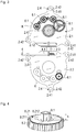
- first gears 8.1 and second gears 8.2 are provided, which are configured in the illustrated embodiment as gears, in particular spur gears.
- first gear wheels 8.1 and the second gears 8.2 according to the FIG. 4 be configured with a common axis of rotation as a one-piece body.
- the first gears 8.1 and the second gears 8.2 here each have an axial extent h of 2.0 mm.
- the second gears 8.2 have an angular pitch 8.21.
- the angular division 8.21 of each second gear 8.2 is circular.
- the angle divisions 8.21 each consist of an electrically conductive region 8.211 and a non-conductive region 8.212.
- the first gears 8.1 are as in the FIG. 3 After assembly of the first gears 8.1 and the second gears 8.2 are the respective angular divisions 8.21 the second detectors 1.23 for inductive scanning of the angular division 8.21 of the second gears 8.2 axially opposite (see the FIG. 7 ).
- the first gear closest to the later drive 8.1 is mounted on the pin 2.111 with the aid of a small roller bearing.
- the cable in particular the screen 4.1, placed in the second recess 2.12.
- the cable in particular the screen 4.1, placed in the second recess 2.12.
- the device described consisting of the printed circuit board 1, the folded metal body 2 with adhesive gap 3 and the cable 4 and the insulating material 5 is hereinafter referred to as a sensor.
- the sensor comprises a folded metal body 2, which has the first layer 2.1 with a first surface S21 and the second layer 2.2 with a second surface S22.
- the first region 1.1 of the printed circuit board 1 is glued on the first surface S21 and the second region 1.2 of the printed circuit board 1 on the second surface S22.
- the first layer 2.1 and the second layer 2.2 of the metal body 2 are arranged between the first region 1.1 and the second region 1.2 of the printed circuit board 1, so that the first region 1.1 is arranged in a first plane E11 and the second region 1.2 in a second plane E12 are. Between the first layer 2.1 and the second layer 2.2 of the metal body 2 there is an adhesive gap 3.
- the first plane E11 and the second plane E12 are arranged parallel to one another in the illustrated embodiment.
- first layer 2.1 of the metal body 2 has a third surface S23 and the second layer 2.2 of the metal body 2 has a fourth surface S24.
- the third surface S23 and the fourth surface S24 are arranged facing each other and spaced apart by the bonding gap 3.
- the first layer 2.1 of the metal body 2 the recesses 2.11 and the second layer 2.2, the recesses 2.21.
- the web 2.3 of the metal body 2 has a reduced thickness D23, it is flexible, so that the metal body 2 together with the flexible printed circuit board 1 or the web 1.3 of the printed circuit board 1 can be easily bent.
- the thickness or thickness D21 of the first layer 2.1 with 2.5 mm is exactly as large as the thickness D22 of the second layer 2.2.
- the thickness D23 of the third layer 2.3 here is 0.1 mm.
- the printed circuit board 1 or the substrate of the printed circuit board 1 here has a thickness d11 of 0.05 mm or 50 ⁇ m.
- a total thickness of the metal body 2 of about 5.05 mm, so that the metal body 2 between the first and the second region 1.1, 1.2 of the circuit board 1 has a thickness D, which is about 100 times larger than the thickness d11 of the printed circuit board 1 or of the substrate of the printed circuit board 1.
- the output-side first gears 8.1 are beyond their axial extent h within the recesses 2.11, 2.21 which are based on the axial direction between the first plane E11 and the second plane E12.
- first gear wheels 8.1 and second gear wheels 8.2 are mounted from the first surface S21 of the metal body 2 in each case in the recess 2.21 of the second layer 2.2.
- a first gear 8.1 (see, for example, the FIG. 7 ) is disposed beyond its axial extent h within the recess 2.21 of the second layer 2.2.
- this recess is 2.11 between the first plane E11 and the second plane E12, based on the axial direction, ie based on the direction of the axis of rotation A.
- a cover is mounted.
- the folded metal body 2 can now be encapsulated approximately with electrically insulating material 5, so that the electronic components 1.21 and the connection of the cable 4 are protected from external influences.
- encapsulation or potting of the electronic components 1.21 may also be carried out in an earlier production step, for example before the metal body 2 is removed from the metal panel along the contour K so as to protect the electronic components 1.21 from external influences at this stage.
- the sensor can now for example be attached to a machine part, such as a motor housing. It is particularly advantageous for this purpose the design of the metal body 2 with the fastening means 2.4 in the form of holes 2.41 in tabs 2.42, which act as a flange.
- the exactly machined contour K can at least partially serve as a stop surface, so that the fitter 2.42 with its contour K only has to bring to suitably prepared surfaces of the machine part to the stop and then rotates through holes 2.41 screws in threaded holes of the machine part. In this way, a simple and precise installation of the sensor is possible.
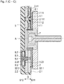
- FIG. 7 is a sectional image of a multi-turn encoder shown, which includes the sensor and a relatively movable (relative to the sensor rotatable) angle scale 7.1.
- the angle scale 7.1 consists of a substrate, which is made in the illustrated embodiment of epoxy resin, and on which two graduation tracks 7.11, 7.12 are arranged.
- the graduation tracks 7.11, 7.12 are circular and arranged with respect to a rotational axis A concentric with different diameters on the substrate.
- the two graduation tracks 7.11, 7.12 each consist of a periodic sequence of alternately arranged electrically conductive graduation regions and nonconductive graduation regions.
- copper was applied to the substrate in the example shown.
- the substrate was not coated in the nonconductive graduation regions.
- the angle scale 7.1 or the angle scaling usually serves as a rotor and is fastened to a machine part which is rotatable about the axis of rotation A.
- the sensor forms the stator of the multi-turn encoder, so that it is fixed to a stationary machine part.
- the angle scale 7.1 and the sensor with a comparatively small air gap face each other.
- the axis of rotation A extends through the center of the shaft 7 and the angle scaling, wherein in a relative rotation between the angular scale 7.1 and the sensor in the circuit board 1, a dependent of the respective angular position signal can be generated by induction effects.
- the multi-turn rotary encoder has the gearbox 8, which is driven by the shaft 7.
- an external toothing is incorporated in the shaft 7 in the illustrated embodiment, which meshes with a first gear 8.1.
- the angular divisions 8.21 are scanned inductively and thus determines a respective angular position of the second gears 8.2.
- the transmission 8 acts as a reduction gear, so that the rotational speeds of the gears 8.1, 8.2 are smaller than that of the shaft. 7
- the mounted on the circuit board 1 ASIC module 1.211 works not only as an evaluation, but also as a exciter control element, under whose control the excitation current, which then flows through the excitation windings 1.11, is generated.
- the exciting current voltages are induced in the first detector 1.12 as a function of the angular position of the shaft 7 or of the angle scaling, these voltages or signals being amplified, demodulated and converted into digital signals by components 1.21 mounted in the second region 1.2 of the printed circuit board 1 ,
- the position values resulting from the scanning of the individual graduation tracks are determined or calculated.
- the determination of the respective angular positions of the second gears 8.2 is carried out according to the same principle as singleturn sampling.
- the position values can be transmitted via the cable 4 to subsequent electronics, for example a numerical control of a machine.
- An angle measuring device equipped with the sensor thus serves to detect an angular position between the sensor, which can be fixed to a machine part, and the angle scale 7.1, which can be fixed to a second machine part, for example a motor shaft. In the manner described The angular position of the shaft 7 can be measured relatively accurately within a revolution.
- the metal body 2 'of the multi-turn encoder of the second embodiment differs from those of the first embodiment, inter alia, in that in the first layer 2.1' pin 2.112 '( FIG. 9 ) are provided, which serve for the storage of the integrally interconnected first gears 8.1 and the second gears 8.2 'with the angle division 8.21'. Furthermore, the second layer 2.2 'comparatively large recesses 2.21', in which the second gears 8.2 'are arranged. In the presented second embodiment, both the first gears 8.1 and the second gears 8.2 'are beyond their axial extent h within the recesses 2.11', 2.21 ', based on the axial direction between the first plane E11 and the second plane E12 are located.
- the scanning of the angular divisions 8.21 'of the second gears 8.2' takes place via a multi-turn sensor 6 'which comprises excitation windings and, as second detectors, receiver coils on a printed circuit board substrate.
- the multi-turn sensor 6 ' is placed on the second surface S22 of the metal body 2' and contacted with the required electronics before insulating material 5 'is applied by encapsulation to protect the metal body 2' and the printed circuit board 1.
Landscapes
- Physics & Mathematics (AREA)
- General Physics & Mathematics (AREA)
- Engineering & Computer Science (AREA)
- Power Engineering (AREA)
- Transmission And Conversion Of Sensor Element Output (AREA)
- Measurement Of Length, Angles, Or The Like Using Electric Or Magnetic Means (AREA)
Priority Applications (4)
| Application Number | Priority Date | Filing Date | Title |
|---|---|---|---|
| EP18159633.9A EP3534121B1 (fr) | 2018-03-02 | 2018-03-02 | Capteur de rotation multitour |
| DE102018220671.6A DE102018220671A1 (de) | 2018-03-02 | 2018-11-30 | Multiturn-Drehgeber |
| JP2019020389A JP7227025B2 (ja) | 2018-03-02 | 2019-02-07 | マルチターンエンコーダ |
| CN201910155518.5A CN110220538B (zh) | 2018-03-02 | 2019-03-01 | 多匝转动编码器 |
Applications Claiming Priority (1)
| Application Number | Priority Date | Filing Date | Title |
|---|---|---|---|
| EP18159633.9A EP3534121B1 (fr) | 2018-03-02 | 2018-03-02 | Capteur de rotation multitour |
Publications (2)
| Publication Number | Publication Date |
|---|---|
| EP3534121A1 true EP3534121A1 (fr) | 2019-09-04 |
| EP3534121B1 EP3534121B1 (fr) | 2021-01-27 |
Family
ID=61557151
Family Applications (1)
| Application Number | Title | Priority Date | Filing Date |
|---|---|---|---|
| EP18159633.9A Active EP3534121B1 (fr) | 2018-03-02 | 2018-03-02 | Capteur de rotation multitour |
Country Status (4)
| Country | Link |
|---|---|
| EP (1) | EP3534121B1 (fr) |
| JP (1) | JP7227025B2 (fr) |
| CN (1) | CN110220538B (fr) |
| DE (1) | DE102018220671A1 (fr) |
Cited By (5)
| Publication number | Priority date | Publication date | Assignee | Title |
|---|---|---|---|---|
| WO2021180425A1 (fr) * | 2020-03-13 | 2021-09-16 | Robert Bosch Gmbh | Agencement de capteur et moteur |
| CN113899389A (zh) * | 2020-06-22 | 2022-01-07 | 约翰内斯.海德汉博士有限公司 | 扫描单元和装备有该扫描单元的旋转编码器 |
| EP3936828A1 (fr) * | 2020-07-09 | 2022-01-12 | Wittenstein Se | Système de capteur pour un entraînement |
| CN114111545A (zh) * | 2020-08-25 | 2022-03-01 | 约翰内斯.海德汉博士有限公司 | 扫描元件和具有该扫描元件的感应式位置测量装置 |
| US12038308B2 (en) | 2021-03-24 | 2024-07-16 | Analog Devices International Unlimited Company | Magnetic sensor system having an initialization conductor |
Families Citing this family (7)
| Publication number | Priority date | Publication date | Assignee | Title |
|---|---|---|---|---|
| EP4230967B1 (fr) * | 2022-02-22 | 2024-04-10 | Dr. Johannes Heidenhain GmbH | Élément palpeur et dispositif inductif de mesure de position pourvu dudit élément palpeur |
| DE102023202516A1 (de) * | 2022-08-09 | 2024-02-15 | Renesas Electronics America Inc. | Induktive Sensoranordnung |
| EP4336148B1 (fr) * | 2022-09-06 | 2024-07-10 | Dr. Johannes Heidenhain GmbH | Élément de balayage et dispositif de mesure de position inductif comprenant ledit élément de balayage |
| GB2626014B (en) * | 2023-01-06 | 2025-04-30 | Mocanu Calin | A system of robots and robotic parts including method of construction and method of use |
| DE102023212111A1 (de) * | 2023-12-04 | 2025-06-05 | Robert Bosch Gesellschaft mit beschränkter Haftung | Winkelsensor zum Abgreifen einer Position eines Verzahnungsträgers und Verfahren zum Betreiben Desselben |
| JP7573140B1 (ja) * | 2024-02-21 | 2024-10-24 | マブチモーター株式会社 | レゾルバステータ及びレゾルバ |
| DE102024107561A1 (de) * | 2024-03-18 | 2025-09-18 | SUMIDA Components & Modules GmbH | Erfassungsvorrichtung für einen Lagegeber und Erfassungssystem mit einer solchen Erfassungsvorrichtung |
Citations (5)
| Publication number | Priority date | Publication date | Assignee | Title |
|---|---|---|---|---|
| EP1391696A2 (fr) * | 2002-08-19 | 2004-02-25 | Stegmann GmbH & Co. KG | Appareil de mesure d'angle multitour |
| US20040078166A1 (en) * | 2002-10-18 | 2004-04-22 | Hyundai Mobis, Co., Ltd. | Detection apparatus for steering angle in vehicle |
| DE102005050016A1 (de) | 2005-10-19 | 2007-04-26 | Dr. Johannes Heidenhain Gmbh | Multiturn-Drehgeber |
| US20160341574A1 (en) * | 2015-05-21 | 2016-11-24 | Okuma Corporation | Multi-turn detector |
| DE102016213697A1 (de) * | 2016-07-26 | 2018-02-01 | Zf Friedrichshafen Ag | Leiterplattenanordnung |
Family Cites Families (6)
| Publication number | Priority date | Publication date | Assignee | Title |
|---|---|---|---|---|
| JPH11132792A (ja) * | 1997-10-31 | 1999-05-21 | Yaskawa Electric Corp | 多回転型アブソリュートエンコーダ |
| JP3521132B2 (ja) * | 2000-07-24 | 2004-04-19 | 株式会社ミツトヨ | 相対変位検出ユニット及び相対変位検出装置 |
| DE10060574A1 (de) * | 2000-12-06 | 2002-06-13 | Heidenhain Gmbh Dr Johannes | Multiturn-Codedrehgeber |
| JP3912049B2 (ja) | 2001-07-02 | 2007-05-09 | 松下電器産業株式会社 | 舵角センサー |
| CN102749026B (zh) * | 2012-07-10 | 2015-01-21 | 万向钱潮(上海)汽车系统有限公司 | 一种绝对式多圈转动角度的检测装置及方法 |
| JP6430800B2 (ja) | 2014-12-02 | 2018-11-28 | 株式会社アイエイアイ | 機械式エンコーダとアクチュエータ |
-
2018
- 2018-03-02 EP EP18159633.9A patent/EP3534121B1/fr active Active
- 2018-11-30 DE DE102018220671.6A patent/DE102018220671A1/de not_active Withdrawn
-
2019
- 2019-02-07 JP JP2019020389A patent/JP7227025B2/ja active Active
- 2019-03-01 CN CN201910155518.5A patent/CN110220538B/zh active Active
Patent Citations (5)
| Publication number | Priority date | Publication date | Assignee | Title |
|---|---|---|---|---|
| EP1391696A2 (fr) * | 2002-08-19 | 2004-02-25 | Stegmann GmbH & Co. KG | Appareil de mesure d'angle multitour |
| US20040078166A1 (en) * | 2002-10-18 | 2004-04-22 | Hyundai Mobis, Co., Ltd. | Detection apparatus for steering angle in vehicle |
| DE102005050016A1 (de) | 2005-10-19 | 2007-04-26 | Dr. Johannes Heidenhain Gmbh | Multiturn-Drehgeber |
| US20160341574A1 (en) * | 2015-05-21 | 2016-11-24 | Okuma Corporation | Multi-turn detector |
| DE102016213697A1 (de) * | 2016-07-26 | 2018-02-01 | Zf Friedrichshafen Ag | Leiterplattenanordnung |
Cited By (7)
| Publication number | Priority date | Publication date | Assignee | Title |
|---|---|---|---|---|
| WO2021180425A1 (fr) * | 2020-03-13 | 2021-09-16 | Robert Bosch Gmbh | Agencement de capteur et moteur |
| US12104930B2 (en) | 2020-03-13 | 2024-10-01 | Robert Bosch Gmbh | Sensor arrangement and motor |
| CN113899389A (zh) * | 2020-06-22 | 2022-01-07 | 约翰内斯.海德汉博士有限公司 | 扫描单元和装备有该扫描单元的旋转编码器 |
| CN113899389B (zh) * | 2020-06-22 | 2025-09-16 | 约翰内斯.海德汉博士有限公司 | 扫描单元和装备有该扫描单元的旋转编码器 |
| EP3936828A1 (fr) * | 2020-07-09 | 2022-01-12 | Wittenstein Se | Système de capteur pour un entraînement |
| CN114111545A (zh) * | 2020-08-25 | 2022-03-01 | 约翰内斯.海德汉博士有限公司 | 扫描元件和具有该扫描元件的感应式位置测量装置 |
| US12038308B2 (en) | 2021-03-24 | 2024-07-16 | Analog Devices International Unlimited Company | Magnetic sensor system having an initialization conductor |
Also Published As
| Publication number | Publication date |
|---|---|
| EP3534121B1 (fr) | 2021-01-27 |
| JP7227025B2 (ja) | 2023-02-21 |
| JP2019152654A (ja) | 2019-09-12 |
| CN110220538B (zh) | 2022-04-19 |
| DE102018220671A1 (de) | 2019-09-05 |
| CN110220538A (zh) | 2019-09-10 |
Similar Documents
| Publication | Publication Date | Title |
|---|---|---|
| EP3534121B1 (fr) | Capteur de rotation multitour | |
| EP3355032B1 (fr) | Capteur de mesure de position | |
| EP2743649B1 (fr) | Dispositif de mesure de position inductif | |
| DE102014208642B4 (de) | Sensoranordnung zur Erfassung von Drehwinkeln an einem rotierenden Bauteil in einem Fahrzeug | |
| EP1906153B1 (fr) | Encodeur et son procédé de fonctionnement | |
| EP1475604B1 (fr) | Capteur d'angle inductif | |
| DE69525819T2 (de) | Kapazitives Verschiebungsmessgerät | |
| EP2105713B1 (fr) | Appareil de mesure de position et son procédé de fonctionnement | |
| DE102009044542B3 (de) | Wälzlager mit einer Sensoreinheit | |
| EP4174443B1 (fr) | Dispositif inductif de mesure d'angle | |
| EP1706716B1 (fr) | Dispositif pour determiner un angle de braquage et un couple de rotation exerce sur un arbre de direction | |
| EP4012351B1 (fr) | Élément de dètection et dispositif de mesure de position inductif pourvu dudit élément de détection | |
| DE102008059775A1 (de) | Absolut messende Lenkwinkelsensoranordnung | |
| DE3821083A1 (de) | Drehmomenterfassungsgeraet | |
| EP4012350B1 (fr) | Élément de détection et dispositif de mesure de position inductif pourvu dudit élément de détection | |
| EP2265902A1 (fr) | Détecteur d angle de rotation inductif et procédé d exploitation d un détecteur d angle de rotation inductif | |
| DE102004056049A1 (de) | Sensor und Verfahren zur Herstellung eines Sensors | |
| EP4031839B1 (fr) | Dispositif de mesure | |
| EP0885375B1 (fr) | Entraínement linéaire avec des capteurs magnétorésistifs | |
| DE4129576C2 (de) | Magnetisches Meßsystem zur Drehwinkelmessung | |
| EP3399284B1 (fr) | Capteur de mesure de position | |
| EP3929539B1 (fr) | Unité de détection et capteur rotatif équipé d'une telle unité de détection | |
| WO1997049996A1 (fr) | Dispositif de transmission sans contact par induction de valeurs electriques de mesure et/ou d'energie electrique entre un rotor et un stator | |
| EP4273507A1 (fr) | Élément de détection et dispositif inductif de mesure de position pourvu dudit élément palpeur | |
| EP4230967A1 (fr) | Élément palpeur et dispositif inductif de mesure de position pourvu dudit élément palpeur |
Legal Events
| Date | Code | Title | Description |
|---|---|---|---|
| PUAI | Public reference made under article 153(3) epc to a published international application that has entered the european phase |
Free format text: ORIGINAL CODE: 0009012 |
|
| STAA | Information on the status of an ep patent application or granted ep patent |
Free format text: STATUS: REQUEST FOR EXAMINATION WAS MADE |
|
| 17P | Request for examination filed |
Effective date: 20180302 |
|
| AK | Designated contracting states |
Kind code of ref document: A1 Designated state(s): AL AT BE BG CH CY CZ DE DK EE ES FI FR GB GR HR HU IE IS IT LI LT LU LV MC MK MT NL NO PL PT RO RS SE SI SK SM TR |
|
| AX | Request for extension of the european patent |
Extension state: BA ME |
|
| STAA | Information on the status of an ep patent application or granted ep patent |
Free format text: STATUS: EXAMINATION IS IN PROGRESS |
|
| 17Q | First examination report despatched |
Effective date: 20200116 |
|
| RBV | Designated contracting states (corrected) |
Designated state(s): AL AT BE BG CH CY CZ DE DK EE ES FI FR GB GR HR HU IE IS IT LI LT LU LV MC MK MT NL NO PL PT RO RS SE SI SK SM TR |
|
| GRAP | Despatch of communication of intention to grant a patent |
Free format text: ORIGINAL CODE: EPIDOSNIGR1 |
|
| STAA | Information on the status of an ep patent application or granted ep patent |
Free format text: STATUS: GRANT OF PATENT IS INTENDED |
|
| INTG | Intention to grant announced |
Effective date: 20200917 |
|
| GRAS | Grant fee paid |
Free format text: ORIGINAL CODE: EPIDOSNIGR3 |
|
| GRAA | (expected) grant |
Free format text: ORIGINAL CODE: 0009210 |
|
| STAA | Information on the status of an ep patent application or granted ep patent |
Free format text: STATUS: THE PATENT HAS BEEN GRANTED |
|
| AK | Designated contracting states |
Kind code of ref document: B1 Designated state(s): AL AT BE BG CH CY CZ DE DK EE ES FI FR GB GR HR HU IE IS IT LI LT LU LV MC MK MT NL NO PL PT RO RS SE SI SK SM TR |
|
| REG | Reference to a national code |
Ref country code: GB Ref legal event code: FG4D Free format text: NOT ENGLISH |
|
| REG | Reference to a national code |
Ref country code: CH Ref legal event code: NV Representative=s name: ICB INGENIEURS CONSEILS EN BREVETS SA, CH Ref country code: CH Ref legal event code: EP |
|
| REG | Reference to a national code |
Ref country code: AT Ref legal event code: REF Ref document number: 1358770 Country of ref document: AT Kind code of ref document: T Effective date: 20210215 |
|
| REG | Reference to a national code |
Ref country code: IE Ref legal event code: FG4D Free format text: LANGUAGE OF EP DOCUMENT: GERMAN |
|
| REG | Reference to a national code |
Ref country code: DE Ref legal event code: R096 Ref document number: 502018003756 Country of ref document: DE |
|
| REG | Reference to a national code |
Ref country code: NL Ref legal event code: MP Effective date: 20210127 |
|
| REG | Reference to a national code |
Ref country code: LT Ref legal event code: MG9D |
|
| PG25 | Lapsed in a contracting state [announced via postgrant information from national office to epo] |
Ref country code: LT Free format text: LAPSE BECAUSE OF FAILURE TO SUBMIT A TRANSLATION OF THE DESCRIPTION OR TO PAY THE FEE WITHIN THE PRESCRIBED TIME-LIMIT Effective date: 20210127 Ref country code: BG Free format text: LAPSE BECAUSE OF FAILURE TO SUBMIT A TRANSLATION OF THE DESCRIPTION OR TO PAY THE FEE WITHIN THE PRESCRIBED TIME-LIMIT Effective date: 20210427 Ref country code: FI Free format text: LAPSE BECAUSE OF FAILURE TO SUBMIT A TRANSLATION OF THE DESCRIPTION OR TO PAY THE FEE WITHIN THE PRESCRIBED TIME-LIMIT Effective date: 20210127 Ref country code: GR Free format text: LAPSE BECAUSE OF FAILURE TO SUBMIT A TRANSLATION OF THE DESCRIPTION OR TO PAY THE FEE WITHIN THE PRESCRIBED TIME-LIMIT Effective date: 20210428 Ref country code: HR Free format text: LAPSE BECAUSE OF FAILURE TO SUBMIT A TRANSLATION OF THE DESCRIPTION OR TO PAY THE FEE WITHIN THE PRESCRIBED TIME-LIMIT Effective date: 20210127 Ref country code: NO Free format text: LAPSE BECAUSE OF FAILURE TO SUBMIT A TRANSLATION OF THE DESCRIPTION OR TO PAY THE FEE WITHIN THE PRESCRIBED TIME-LIMIT Effective date: 20210427 Ref country code: PT Free format text: LAPSE BECAUSE OF FAILURE TO SUBMIT A TRANSLATION OF THE DESCRIPTION OR TO PAY THE FEE WITHIN THE PRESCRIBED TIME-LIMIT Effective date: 20210527 |
|
| PG25 | Lapsed in a contracting state [announced via postgrant information from national office to epo] |
Ref country code: SE Free format text: LAPSE BECAUSE OF FAILURE TO SUBMIT A TRANSLATION OF THE DESCRIPTION OR TO PAY THE FEE WITHIN THE PRESCRIBED TIME-LIMIT Effective date: 20210127 Ref country code: LV Free format text: LAPSE BECAUSE OF FAILURE TO SUBMIT A TRANSLATION OF THE DESCRIPTION OR TO PAY THE FEE WITHIN THE PRESCRIBED TIME-LIMIT Effective date: 20210127 Ref country code: PL Free format text: LAPSE BECAUSE OF FAILURE TO SUBMIT A TRANSLATION OF THE DESCRIPTION OR TO PAY THE FEE WITHIN THE PRESCRIBED TIME-LIMIT Effective date: 20210127 Ref country code: RS Free format text: LAPSE BECAUSE OF FAILURE TO SUBMIT A TRANSLATION OF THE DESCRIPTION OR TO PAY THE FEE WITHIN THE PRESCRIBED TIME-LIMIT Effective date: 20210127 |
|
| PG25 | Lapsed in a contracting state [announced via postgrant information from national office to epo] |
Ref country code: IS Free format text: LAPSE BECAUSE OF FAILURE TO SUBMIT A TRANSLATION OF THE DESCRIPTION OR TO PAY THE FEE WITHIN THE PRESCRIBED TIME-LIMIT Effective date: 20210527 |
|
| REG | Reference to a national code |
Ref country code: DE Ref legal event code: R097 Ref document number: 502018003756 Country of ref document: DE |
|
| PG25 | Lapsed in a contracting state [announced via postgrant information from national office to epo] |
Ref country code: SM Free format text: LAPSE BECAUSE OF FAILURE TO SUBMIT A TRANSLATION OF THE DESCRIPTION OR TO PAY THE FEE WITHIN THE PRESCRIBED TIME-LIMIT Effective date: 20210127 Ref country code: EE Free format text: LAPSE BECAUSE OF FAILURE TO SUBMIT A TRANSLATION OF THE DESCRIPTION OR TO PAY THE FEE WITHIN THE PRESCRIBED TIME-LIMIT Effective date: 20210127 Ref country code: MC Free format text: LAPSE BECAUSE OF FAILURE TO SUBMIT A TRANSLATION OF THE DESCRIPTION OR TO PAY THE FEE WITHIN THE PRESCRIBED TIME-LIMIT Effective date: 20210127 |
|
| PG25 | Lapsed in a contracting state [announced via postgrant information from national office to epo] |
Ref country code: RO Free format text: LAPSE BECAUSE OF FAILURE TO SUBMIT A TRANSLATION OF THE DESCRIPTION OR TO PAY THE FEE WITHIN THE PRESCRIBED TIME-LIMIT Effective date: 20210127 Ref country code: SK Free format text: LAPSE BECAUSE OF FAILURE TO SUBMIT A TRANSLATION OF THE DESCRIPTION OR TO PAY THE FEE WITHIN THE PRESCRIBED TIME-LIMIT Effective date: 20210127 Ref country code: DK Free format text: LAPSE BECAUSE OF FAILURE TO SUBMIT A TRANSLATION OF THE DESCRIPTION OR TO PAY THE FEE WITHIN THE PRESCRIBED TIME-LIMIT Effective date: 20210127 |
|
| PLBE | No opposition filed within time limit |
Free format text: ORIGINAL CODE: 0009261 |
|
| STAA | Information on the status of an ep patent application or granted ep patent |
Free format text: STATUS: NO OPPOSITION FILED WITHIN TIME LIMIT |
|
| REG | Reference to a national code |
Ref country code: BE Ref legal event code: MM Effective date: 20210331 |
|
| 26N | No opposition filed |
Effective date: 20211028 |
|
| PG25 | Lapsed in a contracting state [announced via postgrant information from national office to epo] |
Ref country code: ES Free format text: LAPSE BECAUSE OF FAILURE TO SUBMIT A TRANSLATION OF THE DESCRIPTION OR TO PAY THE FEE WITHIN THE PRESCRIBED TIME-LIMIT Effective date: 20210127 Ref country code: FR Free format text: LAPSE BECAUSE OF NON-PAYMENT OF DUE FEES Effective date: 20210327 Ref country code: IE Free format text: LAPSE BECAUSE OF NON-PAYMENT OF DUE FEES Effective date: 20210302 Ref country code: AL Free format text: LAPSE BECAUSE OF FAILURE TO SUBMIT A TRANSLATION OF THE DESCRIPTION OR TO PAY THE FEE WITHIN THE PRESCRIBED TIME-LIMIT Effective date: 20210127 Ref country code: LU Free format text: LAPSE BECAUSE OF NON-PAYMENT OF DUE FEES Effective date: 20210302 |
|
| PG25 | Lapsed in a contracting state [announced via postgrant information from national office to epo] |
Ref country code: SI Free format text: LAPSE BECAUSE OF FAILURE TO SUBMIT A TRANSLATION OF THE DESCRIPTION OR TO PAY THE FEE WITHIN THE PRESCRIBED TIME-LIMIT Effective date: 20210127 |
|
| PG25 | Lapsed in a contracting state [announced via postgrant information from national office to epo] |
Ref country code: IS Free format text: LAPSE BECAUSE OF FAILURE TO SUBMIT A TRANSLATION OF THE DESCRIPTION OR TO PAY THE FEE WITHIN THE PRESCRIBED TIME-LIMIT Effective date: 20210527 |
|
| PG25 | Lapsed in a contracting state [announced via postgrant information from national office to epo] |
Ref country code: BE Free format text: LAPSE BECAUSE OF NON-PAYMENT OF DUE FEES Effective date: 20210331 |
|
| PG25 | Lapsed in a contracting state [announced via postgrant information from national office to epo] |
Ref country code: NL Free format text: LAPSE BECAUSE OF NON-PAYMENT OF DUE FEES Effective date: 20210127 Ref country code: CY Free format text: LAPSE BECAUSE OF FAILURE TO SUBMIT A TRANSLATION OF THE DESCRIPTION OR TO PAY THE FEE WITHIN THE PRESCRIBED TIME-LIMIT Effective date: 20210127 |
|
| PG25 | Lapsed in a contracting state [announced via postgrant information from national office to epo] |
Ref country code: HU Free format text: LAPSE BECAUSE OF FAILURE TO SUBMIT A TRANSLATION OF THE DESCRIPTION OR TO PAY THE FEE WITHIN THE PRESCRIBED TIME-LIMIT; INVALID AB INITIO Effective date: 20180302 |
|
| PG25 | Lapsed in a contracting state [announced via postgrant information from national office to epo] |
Ref country code: MK Free format text: LAPSE BECAUSE OF FAILURE TO SUBMIT A TRANSLATION OF THE DESCRIPTION OR TO PAY THE FEE WITHIN THE PRESCRIBED TIME-LIMIT Effective date: 20210127 |
|
| REG | Reference to a national code |
Ref country code: AT Ref legal event code: MM01 Ref document number: 1358770 Country of ref document: AT Kind code of ref document: T Effective date: 20230302 |
|
| PG25 | Lapsed in a contracting state [announced via postgrant information from national office to epo] |
Ref country code: AT Free format text: LAPSE BECAUSE OF NON-PAYMENT OF DUE FEES Effective date: 20230302 |
|
| PG25 | Lapsed in a contracting state [announced via postgrant information from national office to epo] |
Ref country code: AT Free format text: LAPSE BECAUSE OF NON-PAYMENT OF DUE FEES Effective date: 20230302 |
|
| PG25 | Lapsed in a contracting state [announced via postgrant information from national office to epo] |
Ref country code: MT Free format text: LAPSE BECAUSE OF FAILURE TO SUBMIT A TRANSLATION OF THE DESCRIPTION OR TO PAY THE FEE WITHIN THE PRESCRIBED TIME-LIMIT Effective date: 20210127 |
|
| PGFP | Annual fee paid to national office [announced via postgrant information from national office to epo] |
Ref country code: CZ Payment date: 20250226 Year of fee payment: 8 |
|
| PGFP | Annual fee paid to national office [announced via postgrant information from national office to epo] |
Ref country code: CH Payment date: 20250401 Year of fee payment: 8 |
|
| PG25 | Lapsed in a contracting state [announced via postgrant information from national office to epo] |
Ref country code: TR Free format text: LAPSE BECAUSE OF FAILURE TO SUBMIT A TRANSLATION OF THE DESCRIPTION OR TO PAY THE FEE WITHIN THE PRESCRIBED TIME-LIMIT Effective date: 20210127 |
|
| REG | Reference to a national code |
Ref country code: CH Ref legal event code: R17 Free format text: ST27 STATUS EVENT CODE: U-0-0-R10-R17 (AS PROVIDED BY THE NATIONAL OFFICE) Effective date: 20260108 |
|
| REG | Reference to a national code |
Ref country code: CH Ref legal event code: U11 Free format text: ST27 STATUS EVENT CODE: U-0-0-U10-U11 (AS PROVIDED BY THE NATIONAL OFFICE) Effective date: 20260401 |
|
| PGFP | Annual fee paid to national office [announced via postgrant information from national office to epo] |
Ref country code: GB Payment date: 20260324 Year of fee payment: 9 |
|
| PGFP | Annual fee paid to national office [announced via postgrant information from national office to epo] |
Ref country code: DE Payment date: 20260319 Year of fee payment: 9 |
|
| PGFP | Annual fee paid to national office [announced via postgrant information from national office to epo] |
Ref country code: AT Payment date: 20260410 Year of fee payment: 5 |
|
| PGFP | Annual fee paid to national office [announced via postgrant information from national office to epo] |
Ref country code: IT Payment date: 20260324 Year of fee payment: 9 |