EP3540208B1 - Anwerfvorrichtung zum starten eines verbrennungsmotors und handgeführtes arbeitsgerät mit einer anwerfvorrichtung - Google Patents
Anwerfvorrichtung zum starten eines verbrennungsmotors und handgeführtes arbeitsgerät mit einer anwerfvorrichtung Download PDFInfo
- Publication number
- EP3540208B1 EP3540208B1 EP19160213.5A EP19160213A EP3540208B1 EP 3540208 B1 EP3540208 B1 EP 3540208B1 EP 19160213 A EP19160213 A EP 19160213A EP 3540208 B1 EP3540208 B1 EP 3540208B1
- Authority
- EP
- European Patent Office
- Prior art keywords
- spring
- coupling
- spring housing
- coupling unit
- starting device
- Prior art date
- Legal status (The legal status is an assumption and is not a legal conclusion. Google has not performed a legal analysis and makes no representation as to the accuracy of the status listed.)
- Active
Links
Images


Classifications
-
- F—MECHANICAL ENGINEERING; LIGHTING; HEATING; WEAPONS; BLASTING
- F02—COMBUSTION ENGINES; HOT-GAS OR COMBUSTION-PRODUCT ENGINE PLANTS
- F02N—STARTING OF COMBUSTION ENGINES; STARTING AIDS FOR SUCH ENGINES, NOT OTHERWISE PROVIDED FOR
- F02N15/00—Other power-operated starting apparatus; Component parts, details, or accessories, not provided for in, or of interest apart from groups F02N5/00 - F02N13/00
- F02N15/02—Gearing between starting-engines and started engines; Engagement or disengagement thereof
- F02N15/022—Gearing between starting-engines and started engines; Engagement or disengagement thereof the starter comprising an intermediate clutch
- F02N15/023—Gearing between starting-engines and started engines; Engagement or disengagement thereof the starter comprising an intermediate clutch of the overrunning type
-
- F—MECHANICAL ENGINEERING; LIGHTING; HEATING; WEAPONS; BLASTING
- F02—COMBUSTION ENGINES; HOT-GAS OR COMBUSTION-PRODUCT ENGINE PLANTS
- F02N—STARTING OF COMBUSTION ENGINES; STARTING AIDS FOR SUCH ENGINES, NOT OTHERWISE PROVIDED FOR
- F02N3/00—Other muscle-operated starting apparatus
- F02N3/02—Other muscle-operated starting apparatus having pull-cords
-
- A—HUMAN NECESSITIES
- A01—AGRICULTURE; FORESTRY; ANIMAL HUSBANDRY; HUNTING; TRAPPING; FISHING
- A01G—HORTICULTURE; CULTIVATION OF VEGETABLES, FLOWERS, RICE, FRUIT, VINES, HOPS OR SEAWEED; FORESTRY; WATERING
- A01G20/00—Cultivation of turf, lawn or the like; Apparatus or methods therefor
- A01G20/40—Apparatus for cleaning the lawn or grass surface
- A01G20/43—Apparatus for cleaning the lawn or grass surface for sweeping, collecting or disintegrating lawn debris
- A01G20/47—Vacuum or blower devices
-
- F—MECHANICAL ENGINEERING; LIGHTING; HEATING; WEAPONS; BLASTING
- F02—COMBUSTION ENGINES; HOT-GAS OR COMBUSTION-PRODUCT ENGINE PLANTS
- F02N—STARTING OF COMBUSTION ENGINES; STARTING AIDS FOR SUCH ENGINES, NOT OTHERWISE PROVIDED FOR
- F02N15/00—Other power-operated starting apparatus; Component parts, details, or accessories, not provided for in, or of interest apart from groups F02N5/00 - F02N13/00
- F02N15/006—Assembling or mounting of starting devices
-
- F—MECHANICAL ENGINEERING; LIGHTING; HEATING; WEAPONS; BLASTING
- F02—COMBUSTION ENGINES; HOT-GAS OR COMBUSTION-PRODUCT ENGINE PLANTS
- F02N—STARTING OF COMBUSTION ENGINES; STARTING AIDS FOR SUCH ENGINES, NOT OTHERWISE PROVIDED FOR
- F02N15/00—Other power-operated starting apparatus; Component parts, details, or accessories, not provided for in, or of interest apart from groups F02N5/00 - F02N13/00
- F02N15/02—Gearing between starting-engines and started engines; Engagement or disengagement thereof
- F02N15/022—Gearing between starting-engines and started engines; Engagement or disengagement thereof the starter comprising an intermediate clutch
- F02N15/027—Gearing between starting-engines and started engines; Engagement or disengagement thereof the starter comprising an intermediate clutch of the pawl type
-
- F—MECHANICAL ENGINEERING; LIGHTING; HEATING; WEAPONS; BLASTING
- F02—COMBUSTION ENGINES; HOT-GAS OR COMBUSTION-PRODUCT ENGINE PLANTS
- F02N—STARTING OF COMBUSTION ENGINES; STARTING AIDS FOR SUCH ENGINES, NOT OTHERWISE PROVIDED FOR
- F02N19/00—Starting aids for combustion engines, not otherwise provided for
- F02N19/001—Arrangements thereof
-
- F—MECHANICAL ENGINEERING; LIGHTING; HEATING; WEAPONS; BLASTING
- F02—COMBUSTION ENGINES; HOT-GAS OR COMBUSTION-PRODUCT ENGINE PLANTS
- F02N—STARTING OF COMBUSTION ENGINES; STARTING AIDS FOR SUCH ENGINES, NOT OTHERWISE PROVIDED FOR
- F02N5/00—Starting apparatus having mechanical power storage
- F02N5/02—Starting apparatus having mechanical power storage of spring type
-
- F—MECHANICAL ENGINEERING; LIGHTING; HEATING; WEAPONS; BLASTING
- F16—ENGINEERING ELEMENTS AND UNITS; GENERAL MEASURES FOR PRODUCING AND MAINTAINING EFFECTIVE FUNCTIONING OF MACHINES OR INSTALLATIONS; THERMAL INSULATION IN GENERAL
- F16D—COUPLINGS FOR TRANSMITTING ROTATION; CLUTCHES; BRAKES
- F16D41/00—Freewheels or freewheel clutches
- F16D41/12—Freewheels or freewheel clutches with hinged pawl co-operating with teeth, cogs, or the like
-
- F—MECHANICAL ENGINEERING; LIGHTING; HEATING; WEAPONS; BLASTING
- F02—COMBUSTION ENGINES; HOT-GAS OR COMBUSTION-PRODUCT ENGINE PLANTS
- F02N—STARTING OF COMBUSTION ENGINES; STARTING AIDS FOR SUCH ENGINES, NOT OTHERWISE PROVIDED FOR
- F02N2250/00—Problems related to engine starting or engine's starting apparatus
Definitions
- the invention relates to a starting device for starting an internal combustion engine and a hand-held working device with a starting device.
- the starting device has a spring accumulator which has a spiral spring arranged in an inner housing.
- a coupling device is arranged on the outer circumference of the inner housing, which only allows the inner housing to rotate in one direction of rotation.
- the starter has a rope reel coupled to the inner housing by a ratchet recoil mechanism.
- the EP 1 645 751 A2 shows a starting device with a centrifugal clutch, the pawl of which engages in a recess on the outer circumference of a spring housing.
- a starting device is known in which the cable pulley is connected to the spring mount via a coupling device.
- the spring mount is connected to a gear.
- the invention is based on the object of creating a starting device for starting an internal combustion engine which has a simplified structure.
- a further object of the invention consists in specifying a hand-held working device with a starting device with an advantageous structure.
- this object is achieved by a starting device having the features of claim 1 .
- the object is achieved by a hand-held work tool having the features of claim 17 .
- the invention provides a starting device with a first coupling device.
- the first coupling device When the cable pulley rotates in a starting direction, the first coupling device establishes a non-rotatable connection between the cable pulley and the spring housing, which acts as a freewheel between the cable pulley and the spring housing when the cable pulley rotates in a direction opposite to the starting direction.
- a tensioning spring of the starting device can be raised and tensioned over several starting strokes.
- the first coupling device has at least one first coupling element and at least one second coupling element, which interact at at least one first contact point when producing the non-rotatable connection between the rope pulley and the spring housing. Provision is made for the at least one first contact point to be at a distance from the axis of rotation which is at least as great as the maximum distance between the tension spring and the axis of rotation.
- the coupling device between the rope pulley and the spring housing is therefore not arranged near the axis of rotation in an installation space formed in the axial direction of the axis of rotation between the rope pulley and the spring receiving space, as is the case in the prior art.
- the first coupling device is arranged in such a way that the at least one first contact point has a radial distance from the axis of rotation that is at least as large as the maximum distance of the tension spring from the axis of rotation. Due to the comparatively large distance between the at least one first contact point and the axis of rotation and the resulting larger lever arm, the coupling elements for transmitting a predetermined torque can be dimensioned comparatively small.
- the axial installation space of the starting device can be reduced by the arrangement of the coupling elements according to the invention, since the spring housing can be arranged closer to the rope pulley in the axial direction of the axis of rotation than in the prior art.
- This is particularly advantageous when using the starting device in hand-held tools, since with hand-held tools the installation space in the direction of the axis of rotation is in many cases essential for the ergonomic handling and usability of the tool.
- a space saving of just a few millimeters can be a clear advantage here bring.
- All the coupling elements of the first coupling device are advantageously located radially between the spring housing and the rope pulley and in particular with their entire extent radially outside the spring receiving space.
- the first coupling device and the tensioning spring overlap in the axial direction of the axis of rotation.
- the first coupling device and the tension spring are therefore not, as in the prior art, arranged next to one another in relation to the axial direction of the axis of rotation.
- the installation space occupied by the tension spring in the axial direction of the axis of rotation and the installation space occupied by the first coupling device in the axial direction of the axis of rotation overlap at least partially.
- An advantageous, compact structure is achieved when one of the two interacting coupling elements of the first coupling device is arranged on the spring housing and the other of the two coupling elements of the first coupling device on a concave inner peripheral surface of the rope pulley.
- the cable pulley at least partially overlaps the spring housing. This enables a particularly advantageous, compact arrangement of the first coupling device.
- a first coupling element and a second coupling element of a second coupling device advantageously interact at a second contact point.
- the at least one second contact point is advantageously at a distance from the axis of rotation which is at least as great as the maximum distance between the tension spring and the axis of rotation.
- Both the first contact point and the second contact point are therefore arranged at a distance from the axis of rotation that is greater than the maximum distance of the tension spring from the axis of rotation.
- the two coupling devices can accordingly be arranged in such a way that their contact points are located radially outside of the tension spring. All coupling elements of the first coupling device and all coupling elements of the second are advantageously located Coupling device radially outside of the spring receiving space.
- the greatest distance between the driver and the axis of rotation is advantageously smaller than the distance between the at least one first contact point and the axis of rotation.
- the greatest distance between the driver and the axis of rotation is in particular smaller than the distance between the at least one second contact point and the axis of rotation.
- the at least one first coupling element of the first coupling device and the at least one coupling element of the second coupling device are each a pawl.
- the at least one second coupling element of the first coupling device and the at least one second coupling element of the second coupling device are each advantageously a locking cam.
- At least one pawl of one coupling device and the at least one latching cam of the other coupling device are preferably arranged on the spring housing.
- locking cams of the first coupling device and locking cams of the second coupling device can be arranged on the spring housing. At least one pawl of the first coupling device and at least one locking cam of the second coupling device are preferably arranged on the spring housing.
- the at least one first contact point of the first coupling device is arranged in a first axial section of the starting device and the at least one second contact point of the second coupling device is arranged in a second axial section of the starting device.
- the first axial section and the second axial section do not overlap in the direction of the axis of rotation.
- the first axial section and the second axial section are at a distance from one another in the axial direction of the axis of rotation. The distance is advantageously chosen so that the coupling elements of the first coupling device cannot interact with the coupling elements of the second coupling device, even in the case of unfavorable tolerances.
- the axial distance is advantageously 1 mm to 15 mm.
- a first longitudinal section of the spring housing is assigned to the first axial section of the starting device, and a second longitudinal section of the spring housing is assigned in particular to the second axial section of the starting device.
- At least one coupling element mounted on the spring housing is advantageously a pawl, and the bearing point of the at least one pawl mounted in the spring housing is arranged radially outside of the spring receiving space in relation to the axis of rotation. This results in a compact construction of the arrangement.
- the entire pawl is arranged radially outside of the spring receiving space in relation to the axis of rotation.
- the first coupling device and the second coupling device overlap in the radial direction of the axis of rotation.
- at least one coupling element of the first coupling device and at least one coupling element of the second coupling device are arranged at approximately the same distance from the axis of rotation.
- the spring housing and the rope pulley particularly advantageously overlap in the axial direction of the axis of rotation.
- the spring housing and the cable pulley preferably overlap in the first axial section of the starting device in the axial direction of the axis of rotation.
- the spring housing advantageously has a width measured in the direction of the axis of rotation.
- the pulley advantageously has a recess into which the spring housing protrudes.
- the rope pulley and the spring housing have an axial overlap that is at least 25% of the width of the spring housing. A compact construction of the starting device is thereby achieved.
- the cable pulley advantageously overlaps the spring housing.
- the spring housing has a bearing dome for mounting the spring housing on a bearing journal of the housing.
- the bearing dome advantageously protrudes into the spring receiving space.
- the bearing dome is therefore at least partially in the same axial space as the tension spring. This achieves a compact structure and a favorable introduction of force to the bearing point. Tilting moments that are generated by the coupling devices on the bearing point of the spring housing can be kept low. Because the first coupling device does not act on the bearing dome, the bearing dome can be arranged in such a way that a favorable introduction of force results.
- the driver advantageously overlaps the bearing dome of the spring housing in the axial direction of the axis of rotation. As a result, a small overall size can be achieved in the axial direction of the axis of rotation. In a particularly advantageous design, the driver engages over the bearing dome of the spring housing.
- At least one coupling device includes at least two first coupling elements that are acted upon by a single spring.
- all the coupling elements of a coupling device are acted upon by a single spring.
- all first coupling elements of the first coupling device are acted upon by a first spring and all first coupling elements of the second coupling device by a second spring.
- the spring is in the form of a ring segment and acts on the at least two first coupling elements in the radial direction in relation to the axis of rotation.
- the spring acts on the coupling elements in the direction of the coupled position, in which the first coupling elements interact with the second coupling elements.
- the working device comprises an internal combustion engine with a crankshaft, and that the starting device is coupled to the crankshaft of the implement via a third coupling device.
- the third coupling device advantageously comprises coupling elements arranged on the driver.
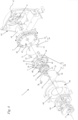
- FIG. 1 shows a blower as an exemplary embodiment of a working device 50, namely a blower carried on the back.
- the starting device according to the invention can also be advantageous for other tools, in particular hand-held tools such as power saws, brush cutters, angle grinders, hand-held blowers or the like.
- the implement 50 has a backpack 51 on which a carrying handle 52 is formed in the exemplary embodiment.
- the implement 50 has a multi-part housing 5. A part of the housing 5 is formed by a starter housing 65, which is part of a starter device 1.
- a starter handle 62 of the starter device 1 is shown schematically.
- the tool 50 also includes a fan coil 56 to which a blower tube 57 is connected.
- the working device 50 conveys a blown air stream through the blower spiral 56 and the blower tube 57, which can be used as a working air stream, for example for removing leaves or the like.
- the backpack 51 includes, in particular 2 shows a back plate 53 and a bottom plate 54.
- the backpack 51 is carried by an operator 63 with carrying straps 55 on the back.
- a fuel tank 64 is arranged outside of the housing 5 in the exemplary embodiment.
- the fuel tank 64 is arranged on the floor panel 54 .
- the housing 5 comprises a motor housing 66 in which an internal combustion engine 2 is arranged.
- the internal combustion engine 2 has a cylinder 59 in which a piston 60 is reciprocally arranged.
- the piston 60 drives a crankshaft 4 in rotation.
- the crankshaft 4 drives a fan wheel 58 in rotation, which promotes the flow of working air.
- the crankshaft 4 is rotatably mounted in a crankcase 61 .
- the starting device 1 is used to start the internal combustion engine 2.
- the structure of the starting device 1 is shown in 3 shown.
- the starter handle 62 ( 1 ) pulls the starter handle 62 ( 1 ).
- the starter rope 67 is on an in 3 shown pulley 3 wound.
- the pull on the starter rope 67 moves the rope pulley 3 in a starter direction 16 ( 4 ) in rotation about an axis of rotation 15.
- the pulley 3 is in the starting direction 16 via a first coupling device 10, which is also in 4 is shown coupled to a spring housing 7 .
- a tension spring 40 is arranged, which is designed as a spiral spring in the embodiment.
- the spring housing 7 there is a spring receiving space 45 in which the tension spring 40 is arranged.
- One end of the tension spring 40 is firmly connected to the spring housing 7 .
- the other end of the tension spring 40 is fixed to a driver 8 .
- the driver 8 is in turn coupled to a flywheel 68 in the starting direction 16 via a third coupling device 30 .
- the flywheel 68 is connected to the crankshaft 4 in a torque-proof manner.
- the spring receiving space 45 is only partially closed towards the driver 8 .
- an annular cover plate 36 is provided which partially closes the spring housing.
- a second coupling device 20 acts on the spring housing 7.
- the second coupling device 20 acts between the spring housing 7 and a retaining plate 69 of the motor housing 66.
- the retaining plate 69 thus forms part of the motor housing 66 and thus a part of the housing 5.
- the retaining plate 69, the motor housing 66 and the starter housing 65 are arranged stationary to one another.
- the pulley 3, the spring housing 7, the tension spring 40, the driver 8 and the flywheel 68 and the crankshaft 4 are rotatably mounted relative to the housing 5 about the axis of rotation 15.
- the pulley 3, the spring housing 7 and the driver 8 are rotatably mounted on a bearing pin 6.
- the bearing journal 6 is firmly connected to the starter housing 65 .
- the second coupling device 20 blocks a rotation of the spring housing 7 against the starting direction. Therefore, at the end of a cranking stroke, the operator can release the starter handle 62 .
- the rope pulley 3 is acted upon by a return spring 9 which rolls up the rope pulley 3 counter to the starting direction 16 .
- the rope pulley 3 is decoupled from the spring housing 7 via the first coupling device 10 .
- the pulley 3 can rotate relative to the spring housing 7 .
- the second coupling device 20 prevents the spring housing 7 from turning back and thus the tensioning spring 40 from relaxing.
- the return spring 9 is arranged in a return spring housing 19 which is open to the side facing away from the rope pulley 3 . This side is closed by the starter housing 65.
- the spring housing 7 has a bearing dome 46 with which it is rotatably mounted on the bearing pin 6 .
- the spring housing 7 has a side wall 42 which runs approximately perpendicular to the axis of rotation 15 in the exemplary embodiment.
- the side wall 42 extends between the bearing dome 46 and a peripheral wall 72 of the spring housing 7.
- the pulley 3 facing The outside of the side wall 42 is flat in the exemplary embodiment.
- the bearing dome 46 projects from the side wall 42 of the spring housing 7 in the direction of the driver 8 and the crankshaft 4.
- the bearing dome 46 projects into the spring receiving space 45 in which the tension spring 40 is arranged. How 3 also shows, an actuating clip 33 of the third coupling device 30 is held on the bearing dome 46 adjacent to the driver 8 .
- the driver 8 has a maximum distance g from the axis of rotation 15. The driver 8 is designed to be comparatively small and does not extend beyond the spring housing 7 in the radial direction toward the axis of rotation 15.
- the first coupling device 10 includes first coupling elements 11, which are designed as pivotably mounted pawls in the exemplary embodiment.
- the first coupling elements 11 are mounted pivotably on the spring housing 7 with bearing pins 25 .
- the first coupling elements 11 each have an actuating pin 27.
- the actuating pins 27 are preloaded by a common first spring 13 in the radial direction toward the axis of rotation 15. The actuating pins 27 are acted upon by the first spring 13 in such a way that the coupling elements 11 are pressed radially outwards.
- the pulley 3 has a recess 43 into which the spring housing 7 protrudes.
- the recess 43 has an inner peripheral surface 44 on which the second coupling elements 12 are provided.
- the second coupling elements 12 are designed as locking cams.
- a plurality of first coupling elements 11 and a plurality of second coupling elements 12 are advantageously provided.
- the number of locking cams is preferably significantly greater than that of the pawls.
- the first coupling elements 11 are biased by the spring 13 in the direction of the inner peripheral surface 44 .
- the first spring 13 is designed as a ring segment. However, it can also be provided that only two coupling elements 11 are acted upon by a common spring 13, or that a separate spring is provided for each coupling element 11.
- the spring housing 7 has holding arms 28 on which the spring 13 is held.
- first coupling elements 11 are designed as latching cams and the second coupling elements 12 are designed as pawls.
- a different configuration of the first and second coupling elements 11, 12 can also be advantageous.
- the spring housing 7 has an outer circumference 41.
- Second coupling elements 22 are arranged on the outer circumference 41.
- Coupling elements 11 of the first coupling device 10 are also arranged on the outer circumference 41, as well 8 shows.
- the second coupling elements 22 are designed as locking cams in the exemplary embodiment.
- the associated first coupling elements 21 are designed as pawls in the exemplary embodiment.
- the first coupling elements 21 each have a bearing journal 26 with which they are pivotably mounted on the motor housing 66 .
- the first coupling elements 21 each have an actuating pin 27 ( figure 5 ), on which they are acted upon by a second spring 23.
- a single second spring 23 is provided for all first coupling elements 21 in the exemplary embodiment.
- the second spring 23 preloads the first coupling elements 21 of the second coupling device 20 radially inwards in the direction of the outer circumference 14 of the spring housing 7 .
- the second spring 23 is designed as a ring segment.
- the two springs 13 and 23 are arranged coaxially to one another and coaxially to the axis of rotation 15 .
- the coupling elements 11, 21, which are designed as pawls in the exemplary embodiment can be in the form of latching elements, in particular latching cams, so that an exactly reverse arrangement results. It can also be expedient to partially design the coupling elements 11, 21, which are designed as pawls in the exemplary embodiment, as latching elements, so that only latches or only latching elements are arranged on the spring housing 7 and accordingly only latching elements or latches are arranged on the cable pulley 3 or the housing 5.
- the third coupling device 30 is provided for connecting the driver 8 to the flywheel 68 .
- the third coupling device 30 has pawls 31 as coupling elements.
- the pawls 31 are mounted on the driver 8 .
- the driver 8 moves relative to the bearing pin 6 in the starting direction 16
- the pawls 31 are pivoted outwards by the actuating clamp 33 so that the pawls 31 can engage with corresponding locking cams on the flywheel 68 .
- the first spring 13 has two spring ends 71 which are bent radially outwards. As a result, the first spring 13 is secured in the circumferential direction on the two actuating pins 27 lying adjacent to the spring ends 71 .
- the first coupling elements 11 arranged on the spring housing 7 in the exemplary embodiment have contact areas 14a
- the second coupling elements 12 of the first coupling device 10 arranged on the rope pulley 3 in the exemplary embodiment have contact areas 14b.
- the first contact point 14 has a minimum distance e from the axis of rotation 15 .
- the distance e is less than or equal to the radius of the recess 43 of the cable pulley 3 and greater than or equal to the radius of the outer circumference 41 of the spring housing 7.
- the first contact points 14 are radially outside of the spring receiving space 45, i.e.
- the spring housing 7 has a first longitudinal section 37 and a second longitudinal section 38.
- the longitudinal section 37 is the longitudinal section in which the first contact points 14 are arranged.
- the longitudinal section 38 is the longitudinal section in which the second contact points 24 are arranged.
- the first longitudinal section 37 is also referred to as the first axial section.
- the second longitudinal section 38 is also referred to as the second axial section.
- the tension spring 40 has an outer end 47 and an inner end 48. With its outer end 47 the tension spring 40 is suspended on the peripheral wall 72 of the spring housing 7 . With its other, inner end 48, the tension spring 40 is hung on a suspension socket 29 of the driver 8. How 2 and 6 show, the suspension socket 29 overlaps the bearing dome 46. The driver 8 and the bearing dome 46 overlap in the axial direction of the axis of rotation 15.
- the bearing journals 25 of the first coupling elements 11 of the first coupling device 10 are mounted in the peripheral wall 72 .
- the first coupling elements 21 of the second coupling device 20 are pivotably mounted on the housing 5, in the exemplary embodiment on the motor housing 66.
- the second coupling elements 22 of the second coupling device 20 are arranged on the outer circumference 41 of the circumferential wall 72 in the second longitudinal section 38 .
- the second coupling elements 22 have contact areas 24b.
- the first coupling elements 21 of the second coupling device 20 mounted on the housing 5 in the exemplary embodiment have contact areas 24a.
- the contact areas 24a and 24b are the areas of the coupling elements 21 and 22 which are in contact with one another when the spring housing 7 and the housing 5 are connected in a rotationally fixed manner come and make the non-rotatable connection.
- the second contact points 24 are at a minimum distance d from the axis of rotation 15 .
- the smallest distance d is measured from the radially innermost area of the contact point 24 .
- the distance d is measured in a radial direction 18 , ie radially to the axis of rotation 15 .
- coupling elements of the first coupling device 10 are arranged in the first longitudinal section 37 of the spring housing 7
- coupling elements of the second coupling device 20 are arranged in the second longitudinal section 38 .
- the tension spring 40 has a maximum distance c from the axis of rotation 15 .
- the maximum distance c from the outer end 47 of the tension spring 40 is measured.
- the distance d of the second contact points 24 to the axis of rotation 15 is greater than the maximum distance c of the tension spring 40 to the axis of rotation 15.
- the second contact points 24 are therefore radially further to the outside than the tension spring 40.
- the second contact points 24 are radially outside of the spring receiving space 45 , So in the same sectional plane perpendicular to the axis of rotation 15, but at a greater radial distance from the axis of rotation 15, respectively.
- the maximum distance g of the driver 8 to the axis of rotation 15 is smaller than the distance e.
- How 6 also shows 5 holding arms 78 are arranged on the housing, on which the second spring 23 is held.
- the second spring 23 acts on the first coupling elements 21 of the second coupling device 20 radially inwards, i.e. in the radial direction 18 in the direction of the axis of rotation 15.
- the second coupling elements 22 deflect the first coupling elements 21 radially outwards against the force of the second spring 23. As a result, the spring housing 7 can be rotated relative to the housing 5 in the starting direction 16 and the tension spring 40 can thus be tensioned.
- a rotation of the spring housing 7 relative to the housing 5 in the opposite direction 17 is of the first coupling elements 21 and the second coupling elements 22 blocked.
- the coupling elements 21 , 22 come into contact with one another at second contact points 24 .
- four first coupling elements 21 and ten second coupling elements 22 are provided.
- a different configuration of the coupling elements 21, 22 can also be advantageous.
- the bearing pins 25 of the first coupling elements 11 have a slot 34 and locking projections 35.
- the bearing pins 25 are in receiving openings 39 of the spring housing 7 ( 10 ) clipped in.
- the bearing journals 26 of the first coupling elements 21 of the second coupling device 20 are designed accordingly and are clipped into corresponding receiving openings (not shown) in the retaining plate 69 of the motor housing 66 .
- the spring housing has a width b measured in the direction of the axis of rotation 15 .
- the spring housing 7 protrudes with the first longitudinal section 37 into the recess 43 of the rope pulley 3.
- the spring housing 7 is partially overlapped by the rope pulley 3 on its outer circumference.
- the rope pulley 3 and the spring housing 7 have an axial overlap f that is at least 25%, in particular at least 30%, of the width b of the spring housing 7 .
- the axial overlap f and the width b are measured parallel to one another and in the direction of the axis of rotation 15 .
- the axial overlap f results in a small axial overall width of the starting device 1.
- the axial overlap f is advantageously less than 70%, in particular less than 50%, of the width b.
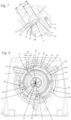
- 8 shows a section through the first coupling device 10. In 8 is also the first contact point 14 located with the contact areas 14a and 14b. How 8 also shows the second coupling elements 12 of the first coupling device 10 and the second coupling elements 22 of the second coupling device 20 are arranged at approximately the same distance from the axis of rotation 15 .
- All coupling elements 11, 12 of the first coupling device 10 are located in a first annular space 80.
- the first annular space 80 extends between an inner boundary 82 and an outer boundary 83, which in 8 are marked with a dashed line.
- All coupling elements 21, 22 of the second coupling device 20 are located in a second annular space 81.
- the second annular space 81 extends between an inner boundary 84 and an outer boundary 85, which in 8 are marked with a dotted line.
- the first annular space 80 and the second annular space 81 are located radially outside of the spring receiving space 45.
- the first annular space 80 and the second annular space 81 overlap, viewed in the direction of the axis of rotation 15, at least partially.
- the first coupling device 10 and the second coupling device 20 thus overlap in the radial direction of the axis of rotation 15.
- the two annular spaces 80 and 81 are next to one another, in particular at a small distance from one another.
- the arrangement of the two coupling devices 10 and 20 is shown in detail. Only the first coupling elements 11 of the first coupling device 10 are shown. The first coupling elements 11 of the first coupling device 10 are mounted radially inside the contact areas 14a. The first coupling elements 21 of the second coupling device 20 are mounted radially outside of the contact areas 24a. The pawls that form the first coupling elements 11 and the first coupling elements 21 are advantageously of identical design. How 9 and 10 show, demolding openings 79 are formed adjacent to the retaining arms 28 on the spring housing 7, so that the retaining arms 28 can be produced integrally with the spring housing 7 in a casting process.
- FIG 10 shows the arrangement of the second coupling elements 22 of the second coupling device 20 in the second longitudinal section 38 on the outer circumference 41 of the spring housing 7.
- the spring housing 7 has receiving openings 39 into which the first coupling elements 11 of the first coupling device 10 are clipped with their bearing pins 25 ( 7 ).
- a distance h is formed between the first longitudinal section 37 and the second longitudinal section 38 .
- the distance h is preferably about 1 mm to 15 mm, in particular less than 5 mm.
- the width i of the first longitudinal section 37 and the width k of the second longitudinal section 38 are each significantly greater than the distance h.
- the width i and/or the width k is preferably at least twice, in particular at least three times, the distance h. It can also be expedient for the longitudinal sections 37 and 38 to adjoin one another without any spacing. In order to achieve a short axial length, the distance h must be minimized.
- the width i of the first longitudinal section 37 corresponds to the width of the first contact points 14 and in particular to the width of the contact areas 14a on the first coupling elements 11 of the first coupling device 10.
- the width k corresponds to the width of the second contact points 24 and in particular to the width of the second coupling elements 22 of the second coupling device 20.
- the width i and the width k can be approximately the same size.
- the widths i and k as well as the distance h and the width b are each parallel to the axis of rotation 15 ( 3 ) measured.
- the sum of the width i and the width k is advantageously at least 70%, in particular at least 80% of the width b of the spring housing 7.
- the axial overlap f ( 7 ) of the spring housing 7 with the cable pulley 3 is advantageously at least as large as the length i of the first longitudinal section 37.
- the first longitudinal section 37 in particular dips completely into the recess 43 ( 4 ) of the pulley 3.
- the spring receiving space 45 advantageously extends in the axial direction of the axis of rotation 15 over both longitudinal sections 37 and 38 of the spring housing 7.
- the spring receiving space 45 advantageously dips into the recess 43 ( 4 ) of the pulley 3, the side wall 42 of the spring housing 7 lying directly adjacent to the rope pulley 3 in the axial direction of the axis of rotation 15 and the first coupling device 10 lying between the spring receiving space 45 and the inner peripheral surface 44 ( 4 ) of the pulley 3 is arranged.
- the spring housing 7 has a suspension section 49 for suspending the outer end 47 of the tension spring 40.
- the second coupling elements 22 are distributed uniformly on the outer circumference 41 of the spring housing 7. This is also in 13 shown.
- the receiving openings 39 which form the bearing points for the first coupling elements 11, are arranged radially outside of the spring receiving space 45 and in the exemplary embodiment in axial overlap with the spring receiving space 45.
Landscapes
- Engineering & Computer Science (AREA)
- General Engineering & Computer Science (AREA)
- Mechanical Engineering (AREA)
- Chemical & Material Sciences (AREA)
- Combustion & Propulsion (AREA)
- Life Sciences & Earth Sciences (AREA)
- Environmental Sciences (AREA)
- Devices For Conveying Motion By Means Of Endless Flexible Members (AREA)
- Control Of Throttle Valves Provided In The Intake System Or In The Exhaust System (AREA)
- Harvester Elements (AREA)
Description
- Die Erfindung betrifft eine Anwerfvorrichtung zum Starten eines Verbrennungsmotors sowie ein handgeführtes Arbeitsgerät mit einer Anwerfvorrichtung.
- Aus der
DE 102 09 012 B4 ist eine Anwerfvorrichtung für eine Brennkraftmaschine bekannt. Die Anwerfvorrichtung besitzt einen Federspeicher, der eine in einem Innengehäuse angeordnete Spiralfeder aufweist. Am Außenumfang des Innengehäuses ist eine Koppeleinrichtung angeordnet, die nur eine Drehung des Innengehäuses in einer Drehrichtung zulässt. Die Anwerfvorrichtung besitzt eine Seilhaspel, die über einen Ratschen-Rücklaufmechanismus mit dem Innengehäuse gekoppelt ist. - Die
EP 1 645 751 A2 zeigt eine Anwerfvorrichtung mit einer Fliehkraftkupplung, deren Klinke am Außenumfang eines Federgehäuses in eine Vertiefung eingreift. - Aus der
JP 2003-097396 A - Aus der
JP 2004-169553 A - Der Erfindung liegt die Aufgabe zugrunde, eine Anwerfvorrichtung zum Starten eines Verbrennungsmotors zu schaffen, die einen vereinfachten Aufbau besitzt. Eine weitere Aufgabe der Erfindung besteht darin, ein handgeführtes Arbeitsgerät mit einer Anwerfvorrichtung mit vorteilhaftem Aufbau anzugeben.
- Diese Aufgabe wird bezüglich der Anwerfvorrichtung durch eine Anwerfvorrichtung mit den Merkmalen des Anspruchs 1 gelöst. Bezüglich des handgeführten Arbeitsgeräts wird die Aufgabe durch ein handgeführtes Arbeitsgerät mit den Merkmalen des Anspruchs 17 gelöst.
- Die Erfindung sieht eine Anwerfvorrichtung mit einer ersten Koppeleinrichtung vor. Die erste Koppeleinrichtung stellt bei einer Drehbewegung der Seilrolle in einer Anwerfrichtung eine drehfeste Verbindung zwischen der Seilrolle und dem Federgehäuse her, die bei einer Drehbewegung der Seilrolle in einer der Anwerfrichtung entgegengesetzten Gegenrichtung als Freilauf zwischen der Seilrolle und dem Federgehäuse wirkt. Dadurch kann eine Spannfeder der Anwerfvorrichtung über mehrere Anwerfhübe aufgezogen und gespannt werden. Die erste Koppeleinrichtung besitzt mindestens ein erstes Koppelelement und mindestens ein zweites Koppelelement, die bei der Herstellung der drehfesten Verbindung zwischen Seilrolle und Federgehäuse an mindestens einer ersten Kontaktstelle zusammenwirken. Es ist vorgesehen, dass die mindestens eine erste Kontaktstelle zur Drehachse einen Abstand besitzt, der mindestens so groß ist wie der maximale Abstand der Spannfeder zur Drehachse.
- Erfindungsgemäß ist die Koppeleinrichtung zwischen Seilrolle und Federgehäuse demnach nicht wie im Stand der Technik nahe der Drehachse in einem in axialer Richtung der Drehachse zwischen Seilrolle und dem Federaufnahmeraum gebildeten Bauraum angeordnet. Stattdessen ist die erste Koppeleinrichtung so angeordnet, dass die mindestens eine erste Kontaktstelle einen Radialabstand zur Drehachse besitzt, der mindestens so groß ist wie der maximale Abstand der Spannfeder zur Drehachse. Aufgrund des vergleichsweise großen Abstands der mindestens einen ersten Kontaktstelle zur Drehachse und des dadurch bedingten größeren Hebelarms können die Koppelelemente zur Übertragung eines vorgegebenen Drehmoments vergleichsweise klein dimensioniert werden. Es hat sich außerdem gezeigt, dass durch die erfindungsgemäße Anordnung der Koppelelemente der axiale Bauraum der Anwerfvorrichtung verringert werden kann, da das Federgehäuse in axialer Richtung der Drehachse näher an der Seilrolle angeordnet werden kann als im Stand der Technik. Dies ist insbesondere beim Einsatz der Anwerfvorrichtung in handgeführten Arbeitsgeräten vorteilhaft, da bei handgeführten Arbeitsgeräten der Bauraum in Richtung der Drehachse in vielen Fällen wesentlich für die ergonomische Handhabung und Gebrauchstauglichkeit des Arbeitsgeräts ist. Bereits eine Bauraumeinsparung von wenigen Millimetern kann hier einen deutlichen Vorteil bringen. Vorteilhaft liegen alle Koppelelemente der ersten Koppeleinrichtung radial zwischen Federgehäuse und Seilrolle und insbesondere mit ihrer gesamten Ausdehnung radial außerhalb des Federaufnahmeraums.
- In vorteilhafter Gestaltung überdecken sich die erste Koppeleinrichtung und die Spannfeder in axialer Richtung der Drehachse. Die erste Koppeleinrichtung und die Spannfeder sind demnach nicht, wie im Stand der Technik, bezogen auf die axiale Richtung der Drehachse nebeneinander angeordnet. Mit anderen Worten ist vorteilhaft vorgesehen, dass der Bauraum, den die Spannfeder in axialer Richtung der Drehachse einnimmt, und der Bauraum, den die erste Koppeleinrichtung in axialer Richtung der Drehachse einnimmt, sich mindestens teilweise überschneiden. Dadurch kann auf einfache Weise ein kompakter Aufbau der Anwerfvorrichtung erreicht werden.
- Ein vorteilhafter, kompakter Aufbau wird erreicht, wenn eines der beiden zusammenwirkenden Koppelelemente der ersten Koppeleinrichtung am Federgehäuse angeordnet ist und das andere der beiden Koppelelemente der ersten Koppeleinrichtung an einer konkaven inneren Umfangsfläche der Seilrolle. Hierzu ist besonders bevorzugt vorgesehen, dass die Seilrolle das Federgehäuse mindestens teilweise übergreift. Dadurch wird eine besonders vorteilhafte, kompakte Anordnung der ersten Koppeleinrichtung ermöglicht.
- Vorteilhaft wirken ein erstes Koppelelement und ein zweites Koppelement einer zweiten Koppeleinrichtung an einer zweiten Kontaktstelle zusammen. Die mindestens eine zweite Kontaktstelle besitzt zur Drehachse vorteilhaft einen Abstand, der mindestens so groß ist wie der maximale Abstand der Spannfeder zur Drehachse. Sowohl die erste Kontaktstelle als auch die zweite Kontaktstelle sind demnach in einem Abstand zur Drehachse angeordnet, der größer als der maximale Abstand der Spannfeder zur Drehachse ist. Die beiden Koppeleinrichtungen können demnach so angeordnet werden, dass ihre Kontaktstellen radial außerhalb der Spannfeder liegen. Vorteilhaft liegen alle Koppelelemente der ersten Koppeleinrichtung und alle Koppelelemente der zweiten Koppeleinrichtung radial außerhalb des Federaufnahmeraums. Der größte Abstand des Mitnehmers zur Drehachse ist vorteilhaft kleiner als der Abstand der mindestens einen ersten Kontaktstelle zur Drehachse. Der größte Abstand des Mitnehmers zur Drehachse ist insbesondere kleiner als der Abstand der mindestens einer zweiten Kontaktstelle zur Drehachse.
- In bevorzugter Ausführung sind das mindestens eine erste Koppelement der ersten Koppeleinrichtung und das mindestens eine Koppelement der zweiten Koppeleinrichtung jeweils eine Klinke. Das mindestens eine zweite Koppelement der ersten Koppeleinrichtung und das mindestens eine zweite Koppelelement der zweiten Koppeleinrichtung sind vorteilhaft jeweils ein Rastnocken. Bevorzugt ist am Federgehäuse mindestens eine Klinke der einen Koppeleinrichtung und der mindestens eine Rastnocken der anderen Koppeleinrichtung angeordnet. Dadurch ergibt sich ein einfacher, vorteilhafter Aufbau. Es kann jedoch auch zweckmäßig sein, am Federgehäuse gleichartige Koppelelemente für die erste Koppeleinrichtung und die zweite Koppeleinrichtung vorzusehen. Am Federgehäuse können demnach beispielweise Klinken der ersten Koppeleinrichtung und Klinken der zweiten Koppeleinrichtung angeordnet sein. In alternativer Ausführung können am Federgehäuse Rastnocken der ersten Koppeleinrichtung und Rastnocken der zweiten Koppeleinrichtung angeordnet sein. Bevorzugt sind am Federgehäuse mindestens eine Klinke der ersten Koppeleinrichtung und mindestens ein Rastnocken der zweiten Koppeleinrichtung angeordnet.
- In besonders vorteilhafter Gestaltung ist die mindestens eine erste Kontaktstelle der ersten Koppeleinrichtung in einem ersten axialen Abschnitt der Anwerfvorrichtung angeordnet und die mindestens eine zweite Kontaktstelle der zweiten Koppeleinrichtung ist in einem zweiten axialen Abschnitt der Anwerfvorrichtung angeordnet. Der erste axiale Abschnitt und der zweite axiale Abschnitt überlappen sich vorteilhaft nicht in Richtung der Drehachse. In besonders vorteilhafter Gestaltung besitzen der erste axiale Abschnitt und der zweite axiale Abschnitt in axialer Richtung der Drehachse einen Abstand zueinander. Der Abstand ist dabei vorteilhaft so gewählt, dass die Koppelelemente der ersten Koppeleinrichtung auch bei ungünstiger Toleranzlage nicht mit den Koppelelementen der zweiten Koppeleinrichtung zusammenwirken können. Der axiale Abstand beträgt vorteilhaft 1 mm bis 15 mm. Dem ersten axialen Abschnitt der Anwerfvorrichtung ist insbesondere ein erster Längsabschnitt des Federgehäuses zugeordnet, und dem zweiten axialen Abschnitt der Anwerfvorrichtung ist insbesondere ein zweiter Längsabschnitt des Federgehäuses zugeordnet.
- Vorteilhaft ist mindestens ein am Federgehäuse gelagertes Koppelelement eine Klinke, und die Lagerstelle der mindestens einen im Federgehäuse gelagerten Klinke ist bezogen auf die Drehachse radial außerhalb des Federaufnahmeraums angeordnet. Dadurch ergibt sich ein kompakter Aufbau der Anordnung. In besonders bevorzugter Gestaltung ist die gesamte Klinke bezogen auf die Drehachse radial außerhalb des Federaufnahmeraums angeordnet.
- In vorteilhafter Gestaltung überlappen sich die erste Koppeleinrichtung und die zweite Koppeleinrichtung in radialer Richtung der Drehachse. In besonders vorteilhafter Gestaltung sind mindestens ein Koppelelement der ersten Koppeleinrichtung und mindestens ein Koppelelement der zweiten Koppeleinrichtung in etwa dem gleichen Abstand zur Drehachse angeordnet.
- Besonders vorteilhaft überdecken sich das Federgehäuse und die Seilrolle in axialer Richtung der Drehachse. Das Federgehäuse und die Seilrolle überdecken sich vorzugsweise im ersten axialen Abschnitt der Anwerfvorrichtung in axialer Richtung der Drehachse. Das Federgehäuse besitzt vorteilhaft eine in Richtung der Drehachse gemessene Breite. Die Seilrolle besitzt vorteilhaft eine Ausnehmung, in die das Federgehäuse ragt. Die Seilrolle und das Federgehäuse weisen in besonders vorteilhafter Gestaltung eine axiale Überlappung auf, die mindestens 25% der Breite des Federgehäuses beträgt. Dadurch wird ein kompakter Aufbau der Anwerfvorrichtung erreicht. Vorteilhaft übergreift die Seilrolle das Federgehäuse.
- In bevorzugter Gestaltung besitzt das Federgehäuse einen Lagerdom zur Lagerung des Federgehäuses auf einem Lagerzapfen des Gehäuses. Der Lagerdom ragt vorteilhaft in den Federaufnahmeraum hinein. Der Lagerdom liegt demnach zumindest teilweise im gleichen axialen Bauraum wie die Spannfeder. Dadurch werden ein kompakter Aufbau und eine günstige Krafteinleitung zur Lagerstelle erreicht. Kippmomente, die von den Koppeleinrichtungen auf die Lagerstelle des Federgehäuses erzeugt werden, können gering gehalten werden. Dadurch, dass die erste Koppeleinrichtung nicht am Lagerdom angreift, kann der Lagerdom so angeordnet werden, dass sich eine günstige Krafteinleitung ergibt. Vorteilhaft überlappt der Mitnehmer den Lagerdom des Federgehäuses in axialer Richtung der Drehachse. Dadurch kann eine geringe Baugröße in axialer Richtung der Drehachse erreicht werden. In besonders vorteilhafter Gestaltung übergreift der Mitnehmer den Lagerdom des Federgehäuses.
- In vorteilhafter Gestaltung umfasst mindestens eine Koppeleinrichtung mindestens zwei erste Koppelelemente, die von einer einzigen Feder beaufschlagt sind. In besonders bevorzugter Gestaltung sind alle Koppelelemente einer Koppeleinrichtung von einer einzigen Feder beaufschlagt. Besonders bevorzugt sind alle ersten Koppelelemente der ersten Koppeleinrichtung von einer ersten Feder beaufschlagt und alle ersten Koppelelemente der zweiten Koppeleinrichtung von einer zweiten Feder.
- In vorteilhafter Gestaltung hat die Feder die Form eines Ringsegments und beaufschlagt die mindestens zwei ersten Koppelelemente bezogen auf die Drehachse in radialer Richtung. Die Feder beaufschlagt die Koppelemente in vorteilhafter Gestaltung in Richtung auf die eingekoppelte Stellung, in der die ersten Koppelelemente mit den zweiten Koppelelementen zusammenwirken.
- Für ein handgeführtes Arbeitsgerät mit einer Anwerfvorrichtung nach der Erfindung ist vorgesehen, dass das Arbeitsgerät einen Verbrennungsmotor mit einer Kurbelwelle umfasst, und dass die Anwerfvorrichtung über eine dritte Koppeleinrichtung an die Kurbelwelle des Arbeitsgeräts gekoppelt ist. Die dritte Koppeleinrichtung umfasst vorteilhaft am Mitnehmer angeordnete Koppelelemente.
- Ein Ausführungsbeispiel der Erfindung wird im Folgenden anhand der Zeichnung erläutert. Es zeigen:
- Fig. 1
- eine schematische Ansicht eines Arbeitsgeräts,
- Fig. 2
- eine schematische Darstellung eines Schnitts entlang der Linie II-II aus
Fig. 1 bei der Anordnung des Arbeitsgeräts an einem Bediener, - Fig. 3
- einen Schnitt durch die Anwerfvorrichtung des Arbeitsgeräts aus den
Figuren 1 und 2 entlang der Linie III-III inFig. 5 , - Fig. 4
- eine Explosionsdarstellung der Anwerfvorrichtung aus
Fig. 3 , - Fig. 5
- einen Schnitt entlang der Linie V-V in
Fig. 3 , - Fig. 6
- einen Schnitt entlang der Linie VI-VI in
Fig. 3 , - Fig. 7
- einen Schnitt entlang der Linie VII-VII in
Fig. 5 , - Fig. 8
- einen Schnitt entlang der Linie VIII-VIII in
Fig. 3 , - Fig. 9
- eine perspektivische Ansicht der Anwerfvorrichtung in Blickrichtung von der Seilrolle zum Federgehäuse, wobei die Seilrolle nicht dargestellt ist,
- Fig. 10
- eine perspektivische Darstellung des Federgehäuses,
- Fig. 11
- eine Seitenansicht des Federgehäuses,
- Fig. 12
- eine Seitenansicht des Federgehäuses in Richtung des Pfeils XII-XII in
Fig. 11 , - Fig. 13
- eine Seitenansicht des Federgehäuses in Richtung des Pfeils XIII-XIII in
Fig. 11 . -
Fig. 1 zeigt als Ausführungsbeispiel für ein Arbeitsgerät 50 ein Blasgerät, nämlich ein rückengetragenes Blasgerät. Die erfindungsgemäße Anwerfvorrichtung kann jedoch auch bei anderen Arbeitsgeräten, insbesondere bei handgeführten Arbeitsgeräten wie Motorsägen, Freischneidern, Trennschleifern, handgetragenen Blasgeräten oder dgl. vorteilhaft sein. Das Arbeitsgerät 50 besitzt eine Rückentrage 51, an der im Ausführungsbeispiel ein Tragegriff 52 ausgebildet ist. Das Arbeitsgerät 50 besitzt ein mehrteiliges Gehäuse 5. Ein Teil des Gehäuses 5 wird durch ein Anwerfergehäuse 65 gebildet, das Teil einer Anwerfvorrichtung 1 ist. InFig. 1 ist ein Anwerfgriff 62 der Anwerfvorrichtung 1 schematisch dargestellt. Das Arbeitsgerät 50 umfasst außerdem eine Gebläsespirale 56, an der ein Blasrohr 57 angeschlossen ist. Das Arbeitsgerät 50 fördert durch die Gebläsespirale 56 und das Blasrohr 57 einen Blasluftstrom, der als Arbeitsluftstrom beispielsweise zum Entfernen von Laub oder dgl. genutzt werden kann. - Die Rückentrage 51 umfasst, wie insbesondere
Fig. 2 zeigt, eine Rückenplatte 53 sowie eine Bodenplatte 54. Die Rückentrage 51 wird von einem Bediener 63 mit Traggurten 55 auf dem Rücken getragen. Im Ausführungsbeispiel ist außerhalb des Gehäuses 5 ein Kraftstofftank 64 angeordnet. Der Kraftstofftank 64 ist auf der Bodenplatte 54 angeordnet. Das Gehäuse 5 umfasst neben dem Anwerfergehäuse 65 ein Motorgehäuse 66, in dem ein Verbrennungsmotor 2 angeordnet ist. Der Verbrennungsmotor 2 weist einen Zylinder 59 auf, in dem ein Kolben 60 hin- und hergehend angeordnet ist. Der Kolben 60 treibt eine Kurbelwelle 4 rotierend an. Die Kurbelwelle 4 treibt im Betrieb ein Gebläserad 58 rotierend an, das den Arbeitsluftstrom fördert. Die Kurbelwelle 4 ist in einem Kurbelgehäuse 61 drehbar gelagert. - Die Anwerfvorrichtung 1 dient zum Anwerfen des Verbrennungsmotors 2. Der Aufbau der Anwerfvorrichtung 1 ist in
Fig. 3 gezeigt. Am Anwerfgriff 62 ist ein inFig. 3 mit gestrichelter Linie schematisch dargestelltes Anwerfseil 67 fixiert. Zum Starten des Verbrennungsmotors 2 zieht der Bediener am Anwerfgriff 62 (Fig. 1 ). Das Anwerfseil 67 ist auf einer inFig. 3 gezeigten Seilrolle 3 aufgewickelt. Der Zug am Anwerfseil 67 versetzt die Seilrolle 3 in einer Anwerfrichtung 16 (Fig. 4 ) in Rotation um eine Drehachse 15. Die Seilrolle 3 ist in Anwerfrichtung 16 über eine erste Koppeleinrichtung 10, die auch inFig. 4 gezeigt ist, mit einem Federgehäuse 7 gekoppelt. Im Federgehäuse 7 ist eine Spannfeder 40 angeordnet, die im Ausführungsbeispiel als Spiralfeder ausgebildet ist. Im Federgehäuse 7 ist ein Federaufnahmeraum 45 ausgebildet, in dem die Spannfeder 40 angeordnet ist. Ein Ende der Spannfeder 40 ist mit dem Federgehäuse 7 fest verbunden. Das andere Ende der Spannfeder 40 ist an einem Mitnehmer 8 fixiert. Der Mitnehmer 8 ist seinerseits in Anwerfrichtung 16 über eine dritte Koppeleinrichtung 30 mit einem Schwungrad 68 gekoppelt. Das Schwungrad 68 ist drehfest mit der Kurbelwelle 4 verbunden. Zum Mitnehmer 8 hin ist der Federaufnahmeraum 45 nur teilweise verschlossen. Im Ausführungsbeispiel ist eine ringförmige Abdeckplatte 36 vorgesehen, die das Federgehäuse teilweise verschließt. - Bei Zug am Anwerfseil 67 wird die Seilrolle 3 in Rotation versetzt. Über die erste Koppeleinrichtung 10 nimmt die Seilrolle 3 das Federgehäuse 7 mit. Dadurch wird die Spannfeder 40 aufgezogen. Die Spannfeder 40 spannt den Mitnehmer 8 und über die Koppeleinrichtung 30 die Kurbelwelle 4 in Anwerfrichtung 16 vor. An der Kurbelwelle 4 wirkt eine vom Kolben 60 auf die Kurbelwelle 4 übertragene Gegenkraft, die von dem komprimierten Gas im Brennraum erzeugt wird. Solange die in der Spannfeder 40 gespeicherte Kraft nicht ausreicht, um den Kolben 60 (
Fig. 2 ) über den oberen Totpunkt des Kolbens 60 zu bewegen bzw. um den Verbrennungsmotor 2 zu starten, kann der Bediener durch mehrmaliges Ziehen am Anwerfseil 67 die Spannfeder 40 aufziehen. - Am Federgehäuse 7 wirkt eine zweite Koppeleinrichtung 20. Die zweite Koppeleinrichtung 20 wirkt zwischen dem Federgehäuse 7 und einer Halteplatte 69 des Motorgehäuses 66. Die Halteplatte 69 bildet damit einen Teil des Motorgehäuses 66 und damit einen Teil des Gehäuses 5. Die Halteplatte 69, das Motorgehäuse 66 und das Anwerfergehäuse 65 sind ortsfest zueinander angeordnet. Die Seilrolle 3, das Federgehäuse 7, die Spannfeder 40, der Mitnehmer 8 und das Schwungrad 68 sowie die Kurbelwelle 4 sind gegenüber dem Gehäuse 5 um die Drehachse 15 drehbar gelagert. Hierzu sind Seilrolle 3, Federgehäuse 7 und Mitnehmer 8 auf einem Lagerzapfen 6 drehbar gelagert. Der Lagerzapfen 6 ist fest mit dem Anwerfergehäuse 65 verbunden.
- Die zweite Koppeleinrichtung 20 blockiert eine Drehung des Federgehäuses 7 entgegen der Anwerfrichtung. Am Ende eines Anwerfhubs kann der Bediener daher den Anwerfgriff 62 loslassen. Die Seilrolle 3 ist von einer Rückholfeder 9 beaufschlagt, die die Seilrolle 3 entgegen der Anwerfrichtung 16 aufrollt. Bei dieser Drehung in der der Anwerfrichtung 16 entgegen gerichteten Gegenrichtung 17 (
Fig. 4 ) ist die Seilrolle 3 vom Federgehäuse 7 über die erste Koppeleinrichtung 10 entkoppelt. Die Seilrolle 3 kann sich gegenüber dem Federgehäuse 7 drehen. Ein Zurückdrehen des Federgehäuses 7 und damit ein Entspannen der Spannfeder 40 wird durch die zweite Koppeleinrichtung 20 verhindert. - Wie
Fig. 3 auch zeigt, ist die Rückholfeder 9 in einem Rückholfedergehäuse 19 angeordnet, das zu der der Seilrolle 3 abgewandten Seite hin offen ist. Diese Seite wird vom Anwerfergehäuse 65 verschlossen. WieFig. 3 auch zeigt, besitzt das Federgehäuse 7 einen Lagerdom 46, mit dem es auf dem Lagerzapfen 6 drehbar gelagert ist. Das Federgehäuse 7 besitzt eine Seitenwand 42, die im Ausführungsbeispiel etwa senkrecht zur Drehachse 15 verläuft. Die Seitenwand 42 erstreckt sich zwischen dem Lagerdom 46 und einer Umfangswand 72 des Federgehäuses 7. Die der Seilrolle 3 zugewandte Außenseite der Seitenwand 42 ist im Ausführungsbeispiel eben ausgebildet. Der Lagerdom 46 ragt von der Seitenwand 42 des Federgehäuses 7 in Richtung zum Mitnehmer 8 und zur Kurbelwelle 4. Der Lagerdom 46 ragt in den Federaufnahmeraum 45, in dem die Spannfeder 40 angeordnet ist. WieFig. 3 auch zeigt, ist am Lagerdom 46 benachbart zum Mitnehmer 8 eine Betätigungsklammer 33 der dritten Koppeleinrichtung 30 gehalten. Der Mitnehmer 8 besitzt einen maximalen Abstand g zur Drehachse 15. Der Mitnehmer 8 ist dabei vergleichsweise klein ausgebildet und erstreckt sich in radialer Richtung zur Drehachse 15 nicht über das Federgehäuse 7 hinaus. -
Fig. 4 zeigt den Aufbau der Anwerfvorrichtung 1 im Einzelnen. Die erste Koppeleinrichtung 10 umfasst erste Koppelelemente 11, die im Ausführungsbeispiel als schwenkbar gelagerte Klinken ausgebildet sind. Die ersten Koppelelemente 11 sind mit Lagerzapfen 25 am Federgehäuse 7 schwenkbar gelagert. Die ersten Koppelelemente 11 besitzen jeweils einen Betätigungszapfen 27. Die Betätigungszapfen 27 sind im Ausführungsbeispiel von einer gemeinsamen ersten Feder 13 in radialer Richtung zur Drehachse 15 vorgespannt. Die Betätigungszapfen 27 sind von der ersten Feder 13 so beaufschlagt, dass die Koppelelemente 11 radial nach außen gedrückt werden. Die Seilrolle 3 besitzt eine Ausnehmung 43, in die das Federgehäuse 7 ragt. Die Ausnehmung 43 besitzt eine innere Umfangsfläche 44, an der zweite Koppelelemente 12 vorgesehen sind. Im Ausführungsbeispiel sind die zweiten Koppelelemente 12 als Rastnocken ausgebildet. Vorteilhaft sind mehrere erste Koppelelemente 11 und mehrere zweite Koppelelemente 12 vorgesehen. Vorzugsweise ist die Anzahl der Rastnocken deutlich größer als die der Klinken. Die ersten Koppelelemente 11 werden von der Feder 13 in Richtung auf die innere Umfangsfläche 44 vorgespannt. Die erste Feder 13 ist als Ringsegment ausgebildet. Es kann jedoch auch vorgesehen sein, dass nur zwei Koppelelemente 11 von einer gemeinsamen Feder 13 beaufschlagt sind, oder dass für jedes Koppelelement 11 eine separate Feder vorgesehen ist. Das Federgehäuse 7 besitzt Haltearme 28, an denen die Feder 13 gehalten ist. - Es kann in alternativer Gestaltung vorgesehen sein, dass die ersten Koppelelemente 11 als Rastnocken und die zweiten Koppelelemente 12 als Klinken ausgebildet sind. Auch eine andere Gestaltung der ersten und zweiten Koppelelemente 11, 12 kann vorteilhaft sein.
- Wie
Fig. 4 auch zeigt, ragt der Lagerdom 46 in den Federaufnahmeraum 45. Das Federgehäuse 7 besitzt einen Außenumfang 41. An dem Außenumfang 41 sind zweite Koppelelemente 22 angeordnet. An dem Außenumfang 41 sind außerdem Koppelelemente 11 der ersten Koppeleinrichtung 10 angeordnet, wie auchFig. 8 zeigt. Die zweiten Koppelelemente 22 sind im Ausführungsbeispiel als Rastnocken ausgebildet. Die zugehörigen ersten Koppelelemente 21 sind im Ausführungsbeispiel als Klinken ausgebildet. Die ersten Koppelelemente 21 besitzen jeweils einen Lagerzapfen 26, mit dem sie am Motorgehäuse 66 schwenkbar gelagert sind. Die ersten Koppelelemente 21 besitzen jeweils einen Betätigungszapfen 27 (Fig. 5 ), an dem sie von einer zweiten Feder 23 beaufschlagt sind. Im Ausführungsbeispiel ist eine einzige zweite Feder 23 für alle ersten Koppelelemente 21 vorgesehen. Die zweite Feder 23 spannt die ersten Koppelelemente 21 der zweiten Koppeleinrichtung 20 radial nach innen in Richtung auf den Außenumfang 14 des Federgehäuses 7 vor. Die zweite Feder 23 ist als Ringsegment ausgebildet. Die beiden Federn 13 und 23 sind koaxial zueinander sowie koaxial zur Drehachse 15 angeordnet. - Es kann auch vorgesehen sein, die im Ausführungsbeispiel als Klinken ausgeführten Koppelelemente 11, 21 als Rastelemente, insbesondere als Rastnocken auszubilden, so dass sich eine genau umgekehrte Anordnung ergibt. Es kann auch zweckmäßig sein, die im Ausführungsbeispiel als Klinken ausgeführten Koppelemente 11, 21 teilweise als Rastelemente auszubilden, so dass am Federgehäuse 7 ausschließlich Klinken oder ausschließlich Rastelemente angeordnet sind und entsprechend an der Seilrolle 3 bzw. dem Gehäuse 5 ausschließlich Rastelemente bzw. Klinken.
- Zur Verbindung des Mitnehmers 8 mit dem Schwungrad 68 ist die dritte Koppeleinrichtung 30 vorgesehen. Die dritte Koppeleinrichtung 30 besitzt im Ausführungsbeispiel Klinken 31 als Koppelelemente. Die Klinken 31 sind am Mitnehmer 8 gelagert. Die Klinken 31 werden bei einer Relativbewegung des Mitnehmers 8 gegenüber dem Lagerzapfen 6 in Anwerfrichtung 16 von der Betätigungsklammer 33 nach außen geschwenkt, so dass die Klinken 31 mit entsprechenden Rastnocken am Schwungrad 68 in Eingriff kommen können.
- Wie
Fig. 5 zeigt, besitzt die erste Feder 13 zwei Federenden 71, die radial nach außen umgebogen sind. Dadurch ist die erste Feder 13 in Umfangsrichtung an den beiden benachbart zu den Federenden 71 liegenden Betätigungszapfen 27 gesichert. WieFig. 5 auch zeigt, besitzen die im Ausführungsbeispiel am Federgehäuse 7 angeordneten ersten Koppelelemente 11 Kontaktbereiche 14a, und die im Ausführungsbeispiel an der Seilrolle 3 angeordneten zweiten Koppelemente 12 der ersten Koppeleinrichtung 10 besitzen Kontaktbereiche 14b. In eingekuppeltem Zustand der ersten Koppeleinrichtung 10, also wenn über die erste Koppeleinrichtung 10 eine Drehung der Seilrolle 3 in Anwerfrichtung 16 auf das Federgehäuse 7 übertragen wird, kommen die Kontaktbereiche 14a und 14b an einer ersten Kontaktstelle 14 miteinander in Kontakt und stellen eine in Anwerfrichtung 16 drehfeste Verbindung zwischen Seilrolle 3 und Federgehäuse 7 her. Die erste Kontaktstelle 14 besitzt zur Drehachse 15 einen minimalen Abstand e. Der Abstand e ist kleiner oder gleich dem Radius der Ausnehmung 43 der Seilrolle 3 und größer oder gleich dem Radius des Außenumfangs 41 des Federgehäuses 7. Die ersten Kontaktstellen 14 sind im Ausführungsbeispiel radial außerhalb des Federaufnahmeraums 45, also in der gleichen Schnittebene senkrecht zur Drehachse 15, aber in größerem radialen Abstand zur Drehachse 15, angeordnet. Der Abstand e ist größer als der maximale Abstand g des Mitnehmers 8 zur Drehachse 15 (Fig. 3 ). In Richtung der Drehachse 15 gesehen, liegen alle Kontaktstellen 14 demnach radial außerhalb des Mitnehmers 8. Bei einer Drehung der Seilrolle 3 in Gegenrichtung 17 lenken die zweiten Koppelelemente 12 die ersten Koppelelemente 11 radial nach innen aus. Dadurch ist eine Drehung der Seilrolle 3 gegenüber dem Federgehäuse 7 in Gegenrichtung 17 möglich. WieFig. 5 zeigt, sind im Ausführungsbeispiel vier erste Koppelelemente 11 und zehn zweite Koppelelemente 12 vorgesehen. - Wie
Fig. 11 zeigt, besitzt das Federgehäuse 7 einen ersten Längsabschnitt 37 und einen zweiten Längsabschnitt 38. Der Längsabschnitt 37 ist der Längsabschnitt, in dem die ersten Kontaktstellen 14 angeordnet sind. Der Längsabschnitt 38 ist der Längsabschnitt, in dem die zweiten Kontaktstellen 24 angeordnet sind. Der erste Längsabschnitt 37 wird auch als erster axialer Abschnitt bezeichnet. Der zweite Längsabschnitt 38 wird auch als zweiter axialer Abschnitt bezeichnet. -
Fig. 6 zeigt einen Schnitt durch den Federaufnahmeraum 45 des Federgehäuses 7 in einem Bereich zwischen dem ersten Längsabschnitt 37 und dem zweiten Längsabschnitt 38 des Federgehäuses 7. Wie die Figur zeigt, besitzt die Spannfeder 40 ein äußeres Ende 47 und ein inneres Ende 48. Mit ihrem äußeren Ende 47 ist die Spannfeder 40 an der Umfangswand 72 des Federgehäuses 7 eingehängt. Mit ihrem anderen, inneren Ende 48 ist die Spannfeder 40 an einem Einhängestutzen 29 des Mitnehmers 8 eingehängt. WieFig. 2 undFig. 6 zeigen, übergreift der Einhängestutzen 29 den Lagerdom 46. Der Mitnehmer 8 und der Lagerdom 46 überlappen sich in axialer Richtung der Drehachse 15. - Wie
Fig. 6 auch zeigt, sind die Lagerzapfen 25 der ersten Koppelelemente 11 der ersten Koppeleinrichtung 10 in der Umfangswand 72 gelagert. Die ersten Koppelelemente 21 der zweiten Koppeleinrichtung 20 sind am Gehäuse 5, im Ausführungsbeispiel am Motorgehäuse 66, schwenkbar gelagert. Am Außenumfang 41 der Umfangswand 72 sind im zweiten Längsabschnitt 38 die zweiten Koppelelemente 22 der zweiten Koppeleinrichtung 20 angeordnet. Die zweiten Koppelelemente 22 besitzen Kontaktbereiche 24b. Die im Ausführungsbeispiel am Gehäuse 5 gelagerten ersten Koppelelemente 21 der zweiten Koppeleinrichtung 20 besitzen Kontaktbereiche 24a. Die Kontaktbereiche 24a und 24b sind die Bereiche der Koppelelemente 21 und 22, die bei einer drehfesten Verbindung zwischen dem Federgehäuse 7 und dem Gehäuse 5 miteinander in Kontakt kommen und die drehfeste Verbindung herstellen. Die zweiten Kontaktstellen 24 besitzen zur Drehachse 15 einen minimalen Abstand d. Der kleinste Abstand d ist zum radial innersten Bereich der Kontaktstelle 24 gemessen. Der Abstand d ist dabei in einer Radialrichtung 18, also radial zur Drehachse 15, gemessen. - Am Außenumfang der Umfangswand 72 des Federgehäuses 7 sind im ersten Längsabschnitt 37 des Federgehäuses 7 Koppelelemente der ersten Koppeleinrichtung 10 angeordnet, und im zweiten Längsabschnitt 38 sind Koppelelemente der zweiten Koppeleinrichtung 20 angeordnet.
- Wie
Fig. 6 auch zeigt, besitzt die Spannfeder 40 zur Drehachse 15 einen maximalen Abstand c. Im Ausführungsbeispiel ist der maximale Abstand c zum äußeren Ende 47 der Spannfeder 40 gemessen. Der Abstand d der zweiten Kontaktstellen 24 zur Drehachse 15 ist größer als der maximale Abstand c der Spannfeder 40 zur Drehachse 15. Die zweiten Kontaktstellen 24 liegen demnach radial weiter außen als die Spannfeder 40. Die zweiten Kontaktstellen 24 sind im Ausführungsbeispiel radial außerhalb des Federaufnahmeraums 45, also in der gleichen Schnittebene senkrecht zur Drehachse 15, aber in größerem radialen Abstand zur Drehachse 15, angeordnet. Der maximale Abstand g des Mitnehmers 8 zur Drehachse 15 ist kleiner als der Abstand e. - Wie
Fig. 6 auch zeigt, sind am Gehäuse 5 Haltearme 78 angeordnet, an denen die zweite Feder 23 gehalten ist. Die zweite Feder 23 beaufschlagt die ersten Koppelelemente 21 der zweiten Koppeleinrichtung 20 radial nach innen, also in Radialrichtung 18 in Richtung auf die Drehachse 15. - Wird das Federgehäuse 7 in Anwerfrichtung 16 gedreht, so lenken die zweiten Koppelelemente 22 die ersten Koppelelemente 21 entgegen der Kraft der zweiten Feder 23 radial nach außen aus. Dadurch kann das Federgehäuse 7 gegenüber dem Gehäuse 5 in Anwerfrichtung 16 gedreht und so die Spannfeder 40 gespannt werden. Eine Drehung des Federgehäuses 7 gegenüber dem Gehäuse 5 in Gegenrichtung 17 wird von den ersten Koppelelementen 21 und den zweiten Koppelelementen 22 blockiert. Dabei kommen die Koppelelemente 21, 22 an zweiten Kontaktstellen 24 miteinander in Kontakt. Im Ausführungsbeispiel sind vier erste Koppelelemente 21 und zehn zweite Koppelelemente 22 vorgesehen. Auch eine andere Anzahl erster und/oder zweiter Koppelelemente 21, 22 kann voreilhaft sein. Es kann auch vorgesehen sein, die ersten Koppelelemente 21 als Rastnocken und die zweiten Koppelelemente 22 als Klinken auszubilden. Auch eine andere Gestaltung der Koppelelemente 21, 22 kann vorteilhaft sein.
- Wie
Fig. 7 zeigt, besitzen die Lagerzapfen 25 der ersten Koppelelemente 11 einen Schlitz 34 sowie Rastvorsprünge 35. Die Lagerzapfen 25 sind in Aufnahmeöffnungen 39 des Federgehäuses 7 (Fig. 10 ) eingeklipst. Die Lagerzapfen 26 der ersten Koppelelemente 21 der zweiten Koppeleinrichtung 20 sind entsprechend ausgebildet und in entsprechende, nicht gezeigte Aufnahmeöffnungen der Halteplatte 69 des Motorgehäuses 66 eingeklipst. - Wie
Fig. 7 zeigt, besitzt das Federgehäuse eine in Richtung der Drehachse 15 gemessene Breite b. Das Federgehäuse 7 ragt mit dem ersten Längsabschnitt 37 in die Ausnehmung 43 der Seilrolle 3. An seinem Außenumfang ist das Federgehäuse 7 von der Seilrolle 3 teilweise übergriffen. Die Seilrolle 3 und das Federgehäuse 7 besitzen eine axiale Überlappung f, die mindestens 25%, insbesondere mindestens 30% der Breite b des Federgehäuses 7 beträgt. Die axiale Überlappung f und die Breite b sind dabei parallel zueinander und in Richtung der Drehachse 15 gemessen. Aufgrund der axialen Überlappung f ergibt sich eine geringe axiale Baubreite der Anwerfvorrichtung 1. Die axiale Überlappung f beträgt vorteilhaft weniger als 70%, insbesondere weniger als 50% der Breite b. -
Fig. 8 zeigt einen Schnitt durch die erste Koppeleinrichtung 10. InFig. 8 ist auch die erste Kontaktstelle 14 mit den Kontaktbereichen 14a und 14b eingezeichnet. WieFig. 8 auch zeigt, sind die zweiten Koppelemente 12 der ersten Koppeleinrichtung 10 und die zweiten Koppelelemente 22 der zweiten Koppeleinrichtung 20 im näherungsweise gleichen Abstand zur Drehachse 15 angeordnet. - Alle Koppelelemente 11, 12 der ersten Koppeleinrichtung 10 liegen in einem ersten Ringraum 80. Der erste Ringraum 80 erstreckt sich zwischen einer inneren Begrenzung 82 und einer äußeren Begrenzung 83, die in
Fig. 8 mit gestrichelter Linie eingezeichnet sind. Alle Koppelelemente 21, 22 der zweiten Koppeleinrichtung 20 liegen in einem zweiten Ringraum 81. Der zweite Ringraum 81 erstreckt sich zwischen einer inneren Begrenzung 84 und einer äußeren Begrenzung 85, die inFig. 8 mit punktierter Linie eingezeichnet sind. Der erste Ringraum 80 und der zweite Ringraum 81 liegen radial außerhalb des Federaufnahmeraums 45. Der erste Ringraum 80 und der zweite Ringraum 81 überschneiden sich in Richtung der Drehachse 15 gesehen mindestens teilweise. Damit überlappen sich die erste Koppeleinrichtung 10 und die zweite Koppeleinrichtung 20 in radialer Richtung der Drehachse 15. In axialer Richtung der Drehachse 15 liegen die beiden Ringräume 80 und 81 nebeneinander, insbesondere mit geringem Abstand nebeneinander. - In
Fig. 9 ist die Anordnung der beiden Koppeleinrichtungen 10 und 20 im Einzelnen gezeigt. Dabei sind von der ersten Koppeleinrichtung 10 lediglich die ersten Koppelelemente 11 dargestellt. Die ersten Koppelelemente 11 der ersten Koppeleinrichtung 10 sind radial innerhalb der Kontaktbereiche 14a gelagert. Die ersten Koppelelemente 21 der zweiten Koppeleinrichtung 20 sind radial außerhalb der Kontaktbereiche 24a gelagert. Die Klinken, die die ersten Koppelelemente 11 und die ersten Koppelelemente 21 bilden, sind vorteilhaft identisch ausgebildet. WieFig. 9 undFig. 10 zeigen, sind benachbart zu den Haltearmen 28 am Federgehäuse 7 Entformungsöffnungen 79 ausgebildet, so dass die Haltearme 28 integral mit dem Federgehäuse 7 in einem Gussverfahren herstellbar sind. -
Fig. 10 zeigt die Anordnung der zweiten Koppelelemente 22 der zweiten Koppeleinrichtung 20 im zweiten Längsabschnitt 38 am Außenumfang 41 des Federgehäuses 7. - Wie
Fig. 10 auch zeigt, besitzt das Federgehäuse 7 Aufnahmeöffnungen 39, in die die ersten Koppelelemente 11 der ersten Koppeleinrichtung 10 mit ihren Lagerzapfen 25 eingeklipst sind (Fig. 7 ). - Wie
Fig. 11 zeigt, ist zwischen dem ersten Längsabschnitt 37 und dem zweiten Längsabschnitt 38 ein Abstand h gebildet. Der Abstand h beträgt vorzugsweise etwa 1 mm bis 15 mm, insbesondere weniger als 5 mm. Die Breite i des ersten Längsabschnitts 37 und die Breite k des zweiten Längsabschnitts 38 ist jeweils deutlich größer als der Abstand h. Bevorzugt beträgt die Breite i und/oder die Breite k mindestens das Doppelte, insbesondere mindestens das Dreifache des Abstands h. Es kann auch zweckmäßig sein, dass die Längsabschnitte 37 und 38 ohne Abstand aneinander angrenzen. Um eine kurze axiale Baulänge zu erzielen, ist der Abstand h zu minimieren. Die Breite i des ersten Längsabschnitts 37 entspricht der Breite der ersten Kontaktstellen 14 und insbesondere der Breite der Kontaktbereiche 14a an den ersten Koppelelementen 11 der ersten Koppeleinrichtung 10. Die Breite k entspricht der Breite der zweiten Kontaktstellen 24 und insbesondere der Breite der zweiten Koppelelemente 22 der zweiten Koppeleinrichtung 20. Die Breite i und die Breite k können näherungsweise gleich groß sein. Die Längsabschnitte 37 und 38, in denen die Kontaktstellen 14 bzw. 24 der ersten Koppeleinrichtung 10 und der zweiten Koppeleinrichtung 20 angeordnet sind, überlappen sich in Richtung der Drehachse 15 vorteilhaft nicht. Die Breiten i und k sowie der Abstand h und die Breite b sind jeweils parallel zur Drehachse 15 (Fig. 3 ) gemessen. Die Summe der Breite i und der Breite k beträgt vorteilhaft mindestens 70%, insbesondere mindestens 80% der Breite b des Federgehäuses 7. - Die axiale Überlappung f (
Fig. 7 ) des Federgehäuses 7 mit der Seilrolle 3 ist vorteilhaft mindestens so groß wie die Länge i des ersten Längsabschnitts 37. Der erste Längsabschnitt 37 taucht insbesondere vollständig in die Ausnehmung 43 (Fig. 4 ) der Seilrolle 3 ein. Der Federaufnahmeraum 45 erstreckt sich vorteilhaft in axialer Richtung der Drehachse 15 über beide Längsabschnitte 37 und 38 des Federgehäuses 7. Der Federaufnahmeraum 45 taucht vorteilhaft in die Ausnehmung 43 (Fig. 4 ) der Seilrolle 3 ein, wobei in axialer Richtung der Drehachse 15 die Seitenwand 42 des Federgehäuses 7 direkt benachbart zur Seilrolle 3 liegt und in radialer Richtung die erste Koppeleinrichtung 10 zwischen dem Federaufnahmeraum 45 und der inneren Umfangsfläche 44 (Fig. 4 ) der Seilrolle 3 angeordnet ist. - Wie
Fig. 12 zeigt, besitzt das Federgehäuse 7 zur Einhängung des äußeren Endes 47 der Spannfeder 40 einen Einhängeabschnitt 49. Die zweiten Koppelemente 22 sind gleichmäßig verteilt am Außenumfang 41 des Federgehäuses 7 angeordnet. Dies ist auch inFig. 13 gezeigt. Wie dieFiguren 12 und 13 zeigen, sind die Aufnahmeöffnungen 39, die die Lagerstellen für die ersten Koppelelemente 11 bilden, radial außerhalb des Federaufnahmeraums 45 und im Ausführungsbeispiel in axialer Überdeckung zum Federaufnahmeraum 45 angeordnet.
Claims (17)
- Anwerfvorrichtung zum Starten eines Verbrennungsmotors (2), wobei die Anwerfvorrichtung (1) ein Gehäuse (5) umfasst, gegenüber dem eine Seilrolle (3), ein Federgehäuse (7) und ein Mitnehmer (8) um eine Drehachse (15) drehbar gelagert sind, wobei zwischen dem Gehäuse (5) und der Seilrolle (3) eine Rückholfeder (9) so angeordnet ist, dass sie bei einer Drehbewegung der Seilrolle (3) in einer Anwerfrichtung (16) um die Drehachse (15) gespannt wird, wobei zwischen der Seilrolle (3) und dem Federgehäuse (7) eine erste Koppeleinrichtung (10) bei einer Drehbewegung der Seilrolle (3) in Anwerfrichtung (16) eine drehfeste Verbindung zwischen der Seilrolle (3) und dem Federgehäuse (7) herstellt, und wobei die erste Koppeleinrichtung (10) bei einer Drehbewegung der Seilrolle (3) in einer der Anwerfrichtung (16) entgegengesetzten Gegenrichtung (17) als Freilauf zwischen der Seilrolle (3) und dem Federgehäuse (7) wirkt, wobei das Federgehäuse (7) einen Federaufnahmeraum (45) für eine Spannfeder (40) aufweist, wobei das Federgehäuse (7) mit dem Mitnehmer (8) über die Spannfeder (40) verbunden ist, wobei an einem Außenumfang (41) des Federgehäuses (7) eine zweite Koppeleinrichtung (20) angeordnet ist, die bei einer Drehbewegung der Seilrolle (3) in Anwerfrichtung (16) als Freilauf zwischen dem Federgehäuse (7) und dem Gehäuse (5) wirkt, wobei die zweite Koppeleinrichtung (20) eine Drehbewegung des Federgehäuses (7) gegenüber dem Gehäuse (5) in Gegenrichtung (17) unterbindet, wobei der Mitnehmer (8) zur Kopplung der Anwerfvorrichtung (1) mit einer Motorwelle (4) des Verbrennungsmotors (2) vorgesehen ist, wobei die erste Koppeleinrichtung (10) mindestens ein erstes Koppelelement (11) und mindestens ein zweites Koppelelement (12) umfasst, und wobei das mindestens eine erste Koppelelement (11) der ersten Koppeleinrichtung (10) mit dem mindestens einen zweiten Koppelelement (12) der ersten Koppeleinrichtung (10) bei der Herstellung der drehfesten Verbindung an mindestens einer ersten Kontaktstelle (14) zusammenwirkt, wobei die mindestens eine erste Kontaktstelle (14) zur Drehachse (15) einen Abstand (e) besitzt, der mindestens so groß ist wie der maximale Abstand (c) der Spannfeder (40) zur Drehachse (15),
dadurch gekennzeichnet, dass das Federgehäuse (7) an seinem Außenumfang (41) von der Seilrolle (3) teilweise übergriffen ist. - Anwerfvorrichtung nach Anspruch 1,
dadurch gekennzeichnet, dass die erste Koppeleinrichtung (10) und die Spannfeder (40) sich in axialer Richtung der Drehachse (15) überdecken. - Anwerfvorrichtung nach Anspruch 1 oder 2,
dadurch gekennzeichnet, dass eines der beiden zusammenwirkenden Koppelelemente (11, 12) der ersten Koppeleinrichtung (10) am Federgehäuse (7) angeordnet ist, und dass das andere der beiden Koppelelemente (11, 12) der ersten Koppeleinrichtung (10) an einer konkaven inneren Umfangsfläche (44) der Seilrolle (3) angeordnet ist. - Anwerfvorrichtung nach einem der Ansprüche 1 bis 3,
dadurch gekennzeichnet, dass die zweite Koppeleinrichtung (20) mindestens ein erstes Koppelelement (21) und mindestens ein zweites Koppelelement (22) umfasst, wobei das mindestens eine erste Koppelelement (21) der zweiten Koppeleinrichtung (20) mit dem mindestens einen zweiten Koppelelement (22) der zweiten Koppeleinrichtung (20) beim Unterbinden einer Drehbewegung des Federgehäuses (7) in der Gegenrichtung (17) an mindestens einer zweiten Kontaktstelle (24) zusammenwirkt. - Anwerfvorrichtung nach Anspruch 4,
dadurch gekennzeichnet, dass die mindestens eine zweite Kontaktstelle (24) zur Drehachse (15) einen Abstand (d) besitzt, der mindestens so groß ist wie der maximale Abstand (c) der Spannfeder (40) zur Drehachse (15). - Anwerfvorrichtung nach Anspruch 4 oder 5,
dadurch gekennzeichnet, dass der größte Abstand (g) des Mitnehmers (8) zur Drehachse (15) kleiner ist als der Abstand (e) der mindestens einen ersten Kontaktstelle (14) zur Drehachse (15) und kleiner ist als der Abstand (d) der mindestens einen zweiten Kontaktstelle (24) zur Drehachse (15). - Anwerfvorrichtung nach einem der Ansprüche 4 bis 6,
dadurch gekennzeichnet, dass das mindestens eine erste Koppelelement (11) der ersten Koppeleinrichtung (10) und das mindestens eine Koppelelement (21) der zweiten Koppeleinrichtung (20) jeweils eine Klinke ist, dass das mindestens eine zweite Koppelelement (12) der ersten Koppeleinrichtung (10) und das mindestens eine zweite Koppelelement (22) der zweiten Koppeleinrichtung (20) jeweils ein Rastnocken ist, und dass am Federgehäuse (7) die mindestens eine Klinke der einen Koppeleinrichtung (10, 20) und der mindestens eine Rastnocken der anderen Koppeleinrichtung (10, 20) angeordnet sind. - Anwerfvorrichtung nach einem der Ansprüche 4 bis 7,
dadurch gekennzeichnet, dass die erste Kontaktstelle (14) der ersten Koppeleinrichtung (10) in einem ersten axialen Abschnitt (37) der Anwerfvorrichtung (1) angeordnet ist und die zweite Kontaktstelle (24) der zweiten Koppeleinrichtung (20) in einem zweiten axialen Abschnitt (38) der Anwerfvorrichtung (1) und dass der erste axiale Abschnitt (37) und der zweite axiale Abschnitt (38) sich in Richtung der Drehachse (15) nicht überlappen. - Anwerfvorrichtung nach einem der Ansprüche 1 bis 8,
dadurch gekennzeichnet, dass mindestens ein am Federgehäuse (7) gelagertes Koppelelement (11) eine Klinke ist und dass die Lagerstelle der mindestens einen am Federgehäuse (7) gelagerten Klinke bezogen auf die Drehachse (5) radial außerhalb des Federaufnahmeraums (45) angeordnet ist. - Anwerfvorrichtung nach einem der Ansprüche 1 bis 9,
dadurch gekennzeichnet, dass die erste Koppeleinrichtung (10) und die zweite Koppeleinrichtung (20) sich in radialer Richtung der Drehachse (15) überlappen. - Anwerfvorrichtung nach einem der Ansprüche 1 bis 10,
dadurch gekennzeichnet, dass das Federgehäuse (7) und die Seilrolle (3) sich in axialer Richtung der Drehachse (15) überdecken. - Anwerfvorrichtung nach einem der Ansprüche 1 bis 11,
dadurch gekennzeichnet, dass das Federgehäuse (7) eine in Richtung der Drehachse (15) gemessene Breite (b) aufweist, dass die Seilrolle (3) eine Ausnehmung (43) aufweist, in die das Federgehäuse (7) ragt, und dass die Seilrolle (3) und das Federgehäuse (7) eine axiale Überlappung (f) aufweisen, die mindestens 25% der Breite (b) des Federgehäuses (7) beträgt. - Anwerfvorrichtung nach einem der Ansprüche 1 bis 12,
dadurch gekennzeichnet, dass das Federgehäuse (7) einen Lagerdom (46) zur Lagerung des Federgehäuses (7) auf einem Lagerzapfen (6) des Gehäuses (5) besitzt, und dass der Lagerdom (46) in den Federaufnahmeraum (45) hineinragt. - Anwerfvorrichtung nach Anspruch 13,
dadurch gekennzeichnet, dass der Mitnehmer (8) den Lagerdom (46) des Federgehäuses (7) in axialer Richtung der Drehachse (15) überlappt. - Anwerfvorrichtung nach einem der Ansprühe 1 bis 14,
dadurch gekennzeichnet, dass mindestens eine Koppeleinrichtung (10, 20) mindestens zwei erste Koppelelemente (11, 21) umfasst, und dass die mindestens zwei ersten Koppelelemente (11, 21) von einer einzigen Feder (13, 23) beaufschlagt sind. - Anwerfvorrichtung nach Anspruch 15,
dadurch gekennzeichnet, dass die Feder (13, 23) die Form eines Ringsegments hat und die Feder (13, 23) die mindestens zwei ersten Koppelelemente (11, 21) bezogen auf die Drehachse (15) in radialer Richtung (70) beaufschlagt. - Arbeitsgerät mit einer Anwerfvorrichtung nach einem der Ansprüche 1 bis 16, wobei das Arbeitsgerät (50) einen Verbrennungsmotor (2) mit einer Motorwelle (4) umfasst, und wobei die Anwerfvorrichtung (1) über eine dritte Koppeleinrichtung (30) an die Motorwelle (4) des Arbeitsgeräts (50) gekoppelt ist, wobei die dritte Koppeleinrichtung (30) am Mitnehmer (8) angeordnete Koppelelemente umfasst.
Applications Claiming Priority (1)
| Application Number | Priority Date | Filing Date | Title |
|---|---|---|---|
| DE102018002133.6A DE102018002133A1 (de) | 2018-03-16 | 2018-03-16 | Anwerfvorrichtung zum Starten eines Verbrennungsmotors und handgeführtes Arbeitsgerät mit einer Anwerfvorrichtung |
Publications (3)
| Publication Number | Publication Date |
|---|---|
| EP3540208A2 EP3540208A2 (de) | 2019-09-18 |
| EP3540208A3 EP3540208A3 (de) | 2019-10-23 |
| EP3540208B1 true EP3540208B1 (de) | 2023-07-19 |
Family
ID=65657339
Family Applications (1)
| Application Number | Title | Priority Date | Filing Date |
|---|---|---|---|
| EP19160213.5A Active EP3540208B1 (de) | 2018-03-16 | 2019-03-01 | Anwerfvorrichtung zum starten eines verbrennungsmotors und handgeführtes arbeitsgerät mit einer anwerfvorrichtung |
Country Status (4)
| Country | Link |
|---|---|
| US (1) | US10954910B2 (de) |
| EP (1) | EP3540208B1 (de) |
| CN (1) | CN110273803B (de) |
| DE (1) | DE102018002133A1 (de) |
Families Citing this family (1)
| Publication number | Priority date | Publication date | Assignee | Title |
|---|---|---|---|---|
| SE545241C2 (en) | 2021-10-14 | 2023-06-07 | Husqvarna Ab | Starter pulley arrangement |
Family Cites Families (29)
| Publication number | Priority date | Publication date | Assignee | Title |
|---|---|---|---|---|
| GB441577A (en) * | 1934-02-08 | 1936-01-22 | Pentaverken Ab | Improvements in starting means for internal combustion motors |
| DE1088289B (de) * | 1958-11-19 | 1960-09-01 | Fichtel & Sachs Ag | Seilzugandrehvorrichtung fuer Brennkraftmaschinen mit Kraftuebertragung durch Reibung |
| US3565050A (en) * | 1969-05-16 | 1971-02-23 | Jacobsen Mfg Co | Recoil type of internal combustion engine starter |
| US3754543A (en) * | 1972-03-10 | 1973-08-28 | Briggs & Stratton Corp | Rope starter for small engines |
| US4261437A (en) * | 1978-11-06 | 1981-04-14 | Barnes Group Inc. | Spring operated pull cord re-wind mechanism for engine starters |
| DE3816099A1 (de) * | 1988-05-11 | 1989-11-23 | Hatz Motoren | Anlasser mit handantrieb fuer brennkraftmaschinen |
| JPH0717810Y2 (ja) | 1989-07-19 | 1995-04-26 | 株式会社共立 | 蓄力式始動装置 |
| US5715783A (en) * | 1996-04-30 | 1998-02-10 | Starting Industrial Co., Ltd. | Recoil starter |
| US6199529B1 (en) * | 1998-03-31 | 2001-03-13 | Honda Giken Kogyo Kabushiki Kaisha And Starting Industrial Co., Ltd. | Engine starting apparatus |
| JP3905689B2 (ja) * | 2000-05-24 | 2007-04-18 | 株式会社共立 | リコイルスタータ装置 |
| JP2002327666A (ja) * | 2001-03-01 | 2002-11-15 | Starting Ind Co Ltd | スタータ装置 |
| JP4109838B2 (ja) * | 2001-05-25 | 2008-07-02 | スターテング工業株式会社 | リコイルスタータ装置 |
| US6739303B2 (en) * | 2001-07-18 | 2004-05-25 | Starting Industrial Co., Ltd. | Recoil starter |
| JP2003097396A (ja) * | 2001-09-21 | 2003-04-03 | Showa Kiki Kogyo Kk | ねじりコイルばね蓄力式スタータ装置 |
| US6959680B2 (en) * | 2002-07-24 | 2005-11-01 | Starting Industrial Co., Ltd. | Recoil starter |
| JP3902528B2 (ja) * | 2002-10-02 | 2007-04-11 | スターテング工業株式会社 | リコイルスタータ |
| JP4014998B2 (ja) * | 2002-10-21 | 2007-11-28 | スターテング工業株式会社 | リコイルスタータ |
| CN100523481C (zh) * | 2002-10-21 | 2009-08-05 | 开始工业株式会社 | 一种反冲起动器 |
| JP3813921B2 (ja) * | 2002-11-15 | 2006-08-23 | 株式会社共立 | 内燃エンジンの始動方法及び始動装置 |
| DE20301182U1 (de) * | 2003-01-29 | 2004-06-09 | Dolmar Gmbh | Startvorrichtung für Brennkraftmotor |
| JP4064961B2 (ja) * | 2004-10-06 | 2008-03-19 | スターテング工業株式会社 | リコイルスタータ |
| US7600505B2 (en) * | 2005-03-29 | 2009-10-13 | Walbro Engine Management, L.L.C. | Fuel system purge and starter system |
| US20070012266A1 (en) * | 2005-07-18 | 2007-01-18 | Bengt-Olov Westerlund | Cord starter |
| CN2854115Y (zh) * | 2005-08-09 | 2007-01-03 | 钟李杏枝 | 省力起动装置 |
| US7252065B1 (en) * | 2006-05-11 | 2007-08-07 | Husqvarna Outdoor Products Inc. | Energy storing starting device |
| JP5833910B2 (ja) * | 2011-12-19 | 2015-12-16 | スターテング工業株式会社 | リコイルスタータ機構 |
| DE102015001119B4 (de) * | 2015-01-29 | 2024-11-21 | Andreas Stihl Ag & Co. Kg | Starteinrichtung für einen Verbrennungsmotor und handgeführtes Arbeitsgerät mit einem Verbrennungsmotor und mit einer Starteinrichtung |
| DE102016009755A1 (de) * | 2016-08-10 | 2018-02-15 | Andreas Stihl Ag & Co. Kg | Anwerfvorrichtung für einen Verbrennungsmotor und rückengetragenes Arbeitsgerät mit einem Verbrennungsmotor und mit einer Anwerfvorrichtung für den Verbrennnungsmotor |
| CN206360833U (zh) * | 2016-12-30 | 2017-07-28 | 杭州古力园林机械有限公司 | 一种具有双弹簧结构的油锯启动器 |
-
2018
- 2018-03-16 DE DE102018002133.6A patent/DE102018002133A1/de not_active Withdrawn
-
2019
- 2019-03-01 EP EP19160213.5A patent/EP3540208B1/de active Active
- 2019-03-15 CN CN201910198668.4A patent/CN110273803B/zh active Active
- 2019-03-18 US US16/356,861 patent/US10954910B2/en active Active
Also Published As
| Publication number | Publication date |
|---|---|
| US10954910B2 (en) | 2021-03-23 |
| DE102018002133A1 (de) | 2019-09-19 |
| EP3540208A3 (de) | 2019-10-23 |
| US20190285042A1 (en) | 2019-09-19 |
| EP3540208A2 (de) | 2019-09-18 |
| CN110273803A (zh) | 2019-09-24 |
| CN110273803B (zh) | 2022-10-14 |
Similar Documents
| Publication | Publication Date | Title |
|---|---|---|
| DE19827335B4 (de) | Handgeführte Motorarbeitsmaschine | |
| EP2778472B1 (de) | Feder, Riemenspannvorrichtung und Aggregatanordnung | |
| DE69526528T2 (de) | Schneidwerkzeugaufspannvorrichtung | |
| DE68907285T2 (de) | Halbautomatischer Trimmerkopf. | |
| DE3119367C1 (de) | Vorrichtung zum hydraulischen Betaetigen einer gezogenen Reibungskupplung fuer Kraftfahrzeuge | |
| EP3282119B1 (de) | Anwerfvorrichtung für einen verbrennungsmotor und rückengetragenes arbeitsgerät mit einem verbrennungsmotor und mit einer anwerfvorrichtung für den verbrennungsmotor | |
| DE102008023927A1 (de) | Arbeitsgerät | |
| DE102014007878A1 (de) | Handgeführtes Arbeitsgerät | |
| EP1857319B1 (de) | Vorrichtung für eine Sitzhöhen-Verstelleinrichtung eines Fahrzeugsitzes sowie ausgestatteter Fahrzeugsitz | |
| DE3545566C1 (de) | Automatische Kompressionsdruck-Reduktionsvorrichtung fuer einen Vierzylinder-Motor | |
| EP2813702A2 (de) | Arbeitsgerät mit einem Verbrennungsmotor | |
| DE3832202C1 (en) | Hand-held machine tool | |
| DE2713075C2 (de) | Anwerfvorrichtung für Brennkraftmaschinen | |
| DE102007008327A1 (de) | Starteinrichtung | |
| DE202009010986U1 (de) | Handbetätigter Antriebsmechanismus für eine Industrietür | |
| EP2944442A2 (de) | Handgeführtes arbeitsgerät mit einer kupplung und verfahren zur herstellung einer nut in der umfangswand einer kupplungstrommel eines handgeführten arbeitsgeräts | |
| EP3540208B1 (de) | Anwerfvorrichtung zum starten eines verbrennungsmotors und handgeführtes arbeitsgerät mit einer anwerfvorrichtung | |
| DE2704341A1 (de) | Kupplungsvorrichtung | |
| DE3021268A1 (de) | Vorrichtung zum anlassen eines verbrennungsmotors | |
| DE19833163C2 (de) | Tragbarer Trimmer mit Bremsvorrichtung | |
| EP3744968B1 (de) | Federgehäuse und anwerfvorrichtung mit einem solchen federgehäuse | |
| WO2022073924A1 (de) | Gurtaufroller für einen fahrzeug-sicherheitsgurt | |
| DE60314956T2 (de) | Kupplung | |
| DE69902211T2 (de) | Sicherheitssperrvorrichtung für einen Hebelschalter | |
| DE102015001119B4 (de) | Starteinrichtung für einen Verbrennungsmotor und handgeführtes Arbeitsgerät mit einem Verbrennungsmotor und mit einer Starteinrichtung |
Legal Events
| Date | Code | Title | Description |
|---|---|---|---|
| PUAI | Public reference made under article 153(3) epc to a published international application that has entered the european phase |
Free format text: ORIGINAL CODE: 0009012 |
|
| STAA | Information on the status of an ep patent application or granted ep patent |
Free format text: STATUS: THE APPLICATION HAS BEEN PUBLISHED |
|
| AK | Designated contracting states |
Kind code of ref document: A2 Designated state(s): AL AT BE BG CH CY CZ DE DK EE ES FI FR GB GR HR HU IE IS IT LI LT LU LV MC MK MT NL NO PL PT RO RS SE SI SK SM TR |
|
| AX | Request for extension of the european patent |
Extension state: BA ME |
|
| PUAL | Search report despatched |
Free format text: ORIGINAL CODE: 0009013 |
|
| AK | Designated contracting states |
Kind code of ref document: A3 Designated state(s): AL AT BE BG CH CY CZ DE DK EE ES FI FR GB GR HR HU IE IS IT LI LT LU LV MC MK MT NL NO PL PT RO RS SE SI SK SM TR |
|
| AX | Request for extension of the european patent |
Extension state: BA ME |
|
| RIC1 | Information provided on ipc code assigned before grant |
Ipc: F02N 3/02 20060101AFI20190917BHEP |
|
| STAA | Information on the status of an ep patent application or granted ep patent |
Free format text: STATUS: REQUEST FOR EXAMINATION WAS MADE |
|
| 17P | Request for examination filed |
Effective date: 20200422 |
|
| RBV | Designated contracting states (corrected) |
Designated state(s): AL AT BE BG CH CY CZ DE DK EE ES FI FR GB GR HR HU IE IS IT LI LT LU LV MC MK MT NL NO PL PT RO RS SE SI SK SM TR |
|
| STAA | Information on the status of an ep patent application or granted ep patent |
Free format text: STATUS: EXAMINATION IS IN PROGRESS |
|
| 17Q | First examination report despatched |
Effective date: 20220609 |
|
| GRAP | Despatch of communication of intention to grant a patent |
Free format text: ORIGINAL CODE: EPIDOSNIGR1 |
|
| STAA | Information on the status of an ep patent application or granted ep patent |
Free format text: STATUS: GRANT OF PATENT IS INTENDED |
|
| INTG | Intention to grant announced |
Effective date: 20230309 |
|
| GRAS | Grant fee paid |
Free format text: ORIGINAL CODE: EPIDOSNIGR3 |
|
| GRAA | (expected) grant |
Free format text: ORIGINAL CODE: 0009210 |
|
| STAA | Information on the status of an ep patent application or granted ep patent |
Free format text: STATUS: THE PATENT HAS BEEN GRANTED |
|
| AK | Designated contracting states |
Kind code of ref document: B1 Designated state(s): AL AT BE BG CH CY CZ DE DK EE ES FI FR GB GR HR HU IE IS IT LI LT LU LV MC MK MT NL NO PL PT RO RS SE SI SK SM TR |
|
| REG | Reference to a national code |
Ref country code: GB Ref legal event code: FG4D Free format text: NOT ENGLISH |
|
| REG | Reference to a national code |
Ref country code: CH Ref legal event code: EP |
|
| REG | Reference to a national code |
Ref country code: DE Ref legal event code: R096 Ref document number: 502019008557 Country of ref document: DE |
|
| REG | Reference to a national code |
Ref country code: IE Ref legal event code: FG4D Free format text: LANGUAGE OF EP DOCUMENT: GERMAN |
|
| REG | Reference to a national code |
Ref country code: LT Ref legal event code: MG9D |
|
| REG | Reference to a national code |
Ref country code: NL Ref legal event code: MP Effective date: 20230719 |
|
| PG25 | Lapsed in a contracting state [announced via postgrant information from national office to epo] |
Ref country code: NL Free format text: LAPSE BECAUSE OF FAILURE TO SUBMIT A TRANSLATION OF THE DESCRIPTION OR TO PAY THE FEE WITHIN THE PRESCRIBED TIME-LIMIT Effective date: 20230719 |
|
| PG25 | Lapsed in a contracting state [announced via postgrant information from national office to epo] |
Ref country code: GR Free format text: LAPSE BECAUSE OF FAILURE TO SUBMIT A TRANSLATION OF THE DESCRIPTION OR TO PAY THE FEE WITHIN THE PRESCRIBED TIME-LIMIT Effective date: 20231020 |
|
| PG25 | Lapsed in a contracting state [announced via postgrant information from national office to epo] |
Ref country code: IS Free format text: LAPSE BECAUSE OF FAILURE TO SUBMIT A TRANSLATION OF THE DESCRIPTION OR TO PAY THE FEE WITHIN THE PRESCRIBED TIME-LIMIT Effective date: 20231119 |
|
| PG25 | Lapsed in a contracting state [announced via postgrant information from national office to epo] |
Ref country code: SE Free format text: LAPSE BECAUSE OF FAILURE TO SUBMIT A TRANSLATION OF THE DESCRIPTION OR TO PAY THE FEE WITHIN THE PRESCRIBED TIME-LIMIT Effective date: 20230719 Ref country code: RS Free format text: LAPSE BECAUSE OF FAILURE TO SUBMIT A TRANSLATION OF THE DESCRIPTION OR TO PAY THE FEE WITHIN THE PRESCRIBED TIME-LIMIT Effective date: 20230719 Ref country code: PT Free format text: LAPSE BECAUSE OF FAILURE TO SUBMIT A TRANSLATION OF THE DESCRIPTION OR TO PAY THE FEE WITHIN THE PRESCRIBED TIME-LIMIT Effective date: 20231120 Ref country code: NO Free format text: LAPSE BECAUSE OF FAILURE TO SUBMIT A TRANSLATION OF THE DESCRIPTION OR TO PAY THE FEE WITHIN THE PRESCRIBED TIME-LIMIT Effective date: 20231019 Ref country code: LV Free format text: LAPSE BECAUSE OF FAILURE TO SUBMIT A TRANSLATION OF THE DESCRIPTION OR TO PAY THE FEE WITHIN THE PRESCRIBED TIME-LIMIT Effective date: 20230719 Ref country code: LT Free format text: LAPSE BECAUSE OF FAILURE TO SUBMIT A TRANSLATION OF THE DESCRIPTION OR TO PAY THE FEE WITHIN THE PRESCRIBED TIME-LIMIT Effective date: 20230719 Ref country code: IS Free format text: LAPSE BECAUSE OF FAILURE TO SUBMIT A TRANSLATION OF THE DESCRIPTION OR TO PAY THE FEE WITHIN THE PRESCRIBED TIME-LIMIT Effective date: 20231119 Ref country code: HR Free format text: LAPSE BECAUSE OF FAILURE TO SUBMIT A TRANSLATION OF THE DESCRIPTION OR TO PAY THE FEE WITHIN THE PRESCRIBED TIME-LIMIT Effective date: 20230719 Ref country code: GR Free format text: LAPSE BECAUSE OF FAILURE TO SUBMIT A TRANSLATION OF THE DESCRIPTION OR TO PAY THE FEE WITHIN THE PRESCRIBED TIME-LIMIT Effective date: 20231020 Ref country code: FI Free format text: LAPSE BECAUSE OF FAILURE TO SUBMIT A TRANSLATION OF THE DESCRIPTION OR TO PAY THE FEE WITHIN THE PRESCRIBED TIME-LIMIT Effective date: 20230719 |
|
| PG25 | Lapsed in a contracting state [announced via postgrant information from national office to epo] |
Ref country code: PL Free format text: LAPSE BECAUSE OF FAILURE TO SUBMIT A TRANSLATION OF THE DESCRIPTION OR TO PAY THE FEE WITHIN THE PRESCRIBED TIME-LIMIT Effective date: 20230719 |
|
| REG | Reference to a national code |
Ref country code: DE Ref legal event code: R097 Ref document number: 502019008557 Country of ref document: DE |
|
| PG25 | Lapsed in a contracting state [announced via postgrant information from national office to epo] |
Ref country code: ES Free format text: LAPSE BECAUSE OF FAILURE TO SUBMIT A TRANSLATION OF THE DESCRIPTION OR TO PAY THE FEE WITHIN THE PRESCRIBED TIME-LIMIT Effective date: 20230719 |
|
| PG25 | Lapsed in a contracting state [announced via postgrant information from national office to epo] |
Ref country code: SM Free format text: LAPSE BECAUSE OF FAILURE TO SUBMIT A TRANSLATION OF THE DESCRIPTION OR TO PAY THE FEE WITHIN THE PRESCRIBED TIME-LIMIT Effective date: 20230719 Ref country code: RO Free format text: LAPSE BECAUSE OF FAILURE TO SUBMIT A TRANSLATION OF THE DESCRIPTION OR TO PAY THE FEE WITHIN THE PRESCRIBED TIME-LIMIT Effective date: 20230719 Ref country code: ES Free format text: LAPSE BECAUSE OF FAILURE TO SUBMIT A TRANSLATION OF THE DESCRIPTION OR TO PAY THE FEE WITHIN THE PRESCRIBED TIME-LIMIT Effective date: 20230719 Ref country code: EE Free format text: LAPSE BECAUSE OF FAILURE TO SUBMIT A TRANSLATION OF THE DESCRIPTION OR TO PAY THE FEE WITHIN THE PRESCRIBED TIME-LIMIT Effective date: 20230719 Ref country code: DK Free format text: LAPSE BECAUSE OF FAILURE TO SUBMIT A TRANSLATION OF THE DESCRIPTION OR TO PAY THE FEE WITHIN THE PRESCRIBED TIME-LIMIT Effective date: 20230719 Ref country code: CZ Free format text: LAPSE BECAUSE OF FAILURE TO SUBMIT A TRANSLATION OF THE DESCRIPTION OR TO PAY THE FEE WITHIN THE PRESCRIBED TIME-LIMIT Effective date: 20230719 Ref country code: SK Free format text: LAPSE BECAUSE OF FAILURE TO SUBMIT A TRANSLATION OF THE DESCRIPTION OR TO PAY THE FEE WITHIN THE PRESCRIBED TIME-LIMIT Effective date: 20230719 |
|
| PLBE | No opposition filed within time limit |
Free format text: ORIGINAL CODE: 0009261 |
|
| STAA | Information on the status of an ep patent application or granted ep patent |
Free format text: STATUS: NO OPPOSITION FILED WITHIN TIME LIMIT |
|
| PG25 | Lapsed in a contracting state [announced via postgrant information from national office to epo] |
Ref country code: IT Free format text: LAPSE BECAUSE OF FAILURE TO SUBMIT A TRANSLATION OF THE DESCRIPTION OR TO PAY THE FEE WITHIN THE PRESCRIBED TIME-LIMIT Effective date: 20230719 |
|
| 26N | No opposition filed |
Effective date: 20240422 |
|
| PG25 | Lapsed in a contracting state [announced via postgrant information from national office to epo] |
Ref country code: SI Free format text: LAPSE BECAUSE OF FAILURE TO SUBMIT A TRANSLATION OF THE DESCRIPTION OR TO PAY THE FEE WITHIN THE PRESCRIBED TIME-LIMIT Effective date: 20230719 |
|
| REG | Reference to a national code |
Ref country code: CH Ref legal event code: PL |
|
| PG25 | Lapsed in a contracting state [announced via postgrant information from national office to epo] |
Ref country code: BG Free format text: LAPSE BECAUSE OF FAILURE TO SUBMIT A TRANSLATION OF THE DESCRIPTION OR TO PAY THE FEE WITHIN THE PRESCRIBED TIME-LIMIT Effective date: 20230719 |
|
| PG25 | Lapsed in a contracting state [announced via postgrant information from national office to epo] |
Ref country code: LU Free format text: LAPSE BECAUSE OF NON-PAYMENT OF DUE FEES Effective date: 20240301 |
|
| PG25 | Lapsed in a contracting state [announced via postgrant information from national office to epo] |
Ref country code: MC Free format text: LAPSE BECAUSE OF FAILURE TO SUBMIT A TRANSLATION OF THE DESCRIPTION OR TO PAY THE FEE WITHIN THE PRESCRIBED TIME-LIMIT Effective date: 20230719 |
|
| GBPC | Gb: european patent ceased through non-payment of renewal fee |
Effective date: 20240301 |
|
| PG25 | Lapsed in a contracting state [announced via postgrant information from national office to epo] |
Ref country code: MC Free format text: LAPSE BECAUSE OF FAILURE TO SUBMIT A TRANSLATION OF THE DESCRIPTION OR TO PAY THE FEE WITHIN THE PRESCRIBED TIME-LIMIT Effective date: 20230719 Ref country code: LU Free format text: LAPSE BECAUSE OF NON-PAYMENT OF DUE FEES Effective date: 20240301 Ref country code: BG Free format text: LAPSE BECAUSE OF FAILURE TO SUBMIT A TRANSLATION OF THE DESCRIPTION OR TO PAY THE FEE WITHIN THE PRESCRIBED TIME-LIMIT Effective date: 20230719 |
|
| REG | Reference to a national code |
Ref country code: BE Ref legal event code: MM Effective date: 20240331 |
|
| PG25 | Lapsed in a contracting state [announced via postgrant information from national office to epo] |
Ref country code: BE Free format text: LAPSE BECAUSE OF NON-PAYMENT OF DUE FEES Effective date: 20240331 |
|
| PG25 | Lapsed in a contracting state [announced via postgrant information from national office to epo] |
Ref country code: GB Free format text: LAPSE BECAUSE OF NON-PAYMENT OF DUE FEES Effective date: 20240301 |
|
| PG25 | Lapsed in a contracting state [announced via postgrant information from national office to epo] |
Ref country code: IE Free format text: LAPSE BECAUSE OF NON-PAYMENT OF DUE FEES Effective date: 20240301 |
|
| PG25 | Lapsed in a contracting state [announced via postgrant information from national office to epo] |
Ref country code: IE Free format text: LAPSE BECAUSE OF NON-PAYMENT OF DUE FEES Effective date: 20240301 Ref country code: GB Free format text: LAPSE BECAUSE OF NON-PAYMENT OF DUE FEES Effective date: 20240301 Ref country code: BE Free format text: LAPSE BECAUSE OF NON-PAYMENT OF DUE FEES Effective date: 20240331 Ref country code: CH Free format text: LAPSE BECAUSE OF NON-PAYMENT OF DUE FEES Effective date: 20240331 |
|
| REG | Reference to a national code |
Ref country code: AT Ref legal event code: MM01 Ref document number: 1589714 Country of ref document: AT Kind code of ref document: T Effective date: 20240301 |
|
| PG25 | Lapsed in a contracting state [announced via postgrant information from national office to epo] |
Ref country code: AT Free format text: LAPSE BECAUSE OF NON-PAYMENT OF DUE FEES Effective date: 20240301 |
|
| PG25 | Lapsed in a contracting state [announced via postgrant information from national office to epo] |
Ref country code: CY Free format text: LAPSE BECAUSE OF FAILURE TO SUBMIT A TRANSLATION OF THE DESCRIPTION OR TO PAY THE FEE WITHIN THE PRESCRIBED TIME-LIMIT; INVALID AB INITIO Effective date: 20190301 |
|
| PG25 | Lapsed in a contracting state [announced via postgrant information from national office to epo] |
Ref country code: HU Free format text: LAPSE BECAUSE OF FAILURE TO SUBMIT A TRANSLATION OF THE DESCRIPTION OR TO PAY THE FEE WITHIN THE PRESCRIBED TIME-LIMIT; INVALID AB INITIO Effective date: 20190301 |
|
| PG25 | Lapsed in a contracting state [announced via postgrant information from national office to epo] |
Ref country code: TR Free format text: LAPSE BECAUSE OF FAILURE TO SUBMIT A TRANSLATION OF THE DESCRIPTION OR TO PAY THE FEE WITHIN THE PRESCRIBED TIME-LIMIT Effective date: 20230719 |
|
| PGFP | Annual fee paid to national office [announced via postgrant information from national office to epo] |
Ref country code: DE Payment date: 20260320 Year of fee payment: 8 |
|
| PGFP | Annual fee paid to national office [announced via postgrant information from national office to epo] |
Ref country code: FR Payment date: 20260323 Year of fee payment: 8 |