EP3542109B1 - Schmiermittelseparator mit schalldämpfer - Google Patents
Schmiermittelseparator mit schalldämpfer Download PDFInfo
- Publication number
- EP3542109B1 EP3542109B1 EP16819653.3A EP16819653A EP3542109B1 EP 3542109 B1 EP3542109 B1 EP 3542109B1 EP 16819653 A EP16819653 A EP 16819653A EP 3542109 B1 EP3542109 B1 EP 3542109B1
- Authority
- EP
- European Patent Office
- Prior art keywords
- lubricant
- perforated pipe
- compressor
- refrigerant
- separator
- Prior art date
- Legal status (The legal status is an assumption and is not a legal conclusion. Google has not performed a legal analysis and makes no representation as to the accuracy of the status listed.)
- Active
Links
Images


Classifications
-
- F—MECHANICAL ENGINEERING; LIGHTING; HEATING; WEAPONS; BLASTING
- F25—REFRIGERATION OR COOLING; COMBINED HEATING AND REFRIGERATION SYSTEMS; HEAT PUMP SYSTEMS; MANUFACTURE OR STORAGE OF ICE; LIQUEFACTION SOLIDIFICATION OF GASES
- F25B—REFRIGERATION MACHINES, PLANTS OR SYSTEMS; COMBINED HEATING AND REFRIGERATION SYSTEMS; HEAT PUMP SYSTEMS
- F25B31/00—Compressor arrangements
- F25B31/002—Lubrication
-
- F—MECHANICAL ENGINEERING; LIGHTING; HEATING; WEAPONS; BLASTING
- F25—REFRIGERATION OR COOLING; COMBINED HEATING AND REFRIGERATION SYSTEMS; HEAT PUMP SYSTEMS; MANUFACTURE OR STORAGE OF ICE; LIQUEFACTION SOLIDIFICATION OF GASES
- F25B—REFRIGERATION MACHINES, PLANTS OR SYSTEMS; COMBINED HEATING AND REFRIGERATION SYSTEMS; HEAT PUMP SYSTEMS
- F25B43/00—Arrangements for separating or purifying gases or liquids; Arrangements for vaporising the residuum of liquid refrigerant, e.g. by heat
- F25B43/02—Arrangements for separating or purifying gases or liquids; Arrangements for vaporising the residuum of liquid refrigerant, e.g. by heat for separating lubricants from the refrigerant
-
- F—MECHANICAL ENGINEERING; LIGHTING; HEATING; WEAPONS; BLASTING
- F25—REFRIGERATION OR COOLING; COMBINED HEATING AND REFRIGERATION SYSTEMS; HEAT PUMP SYSTEMS; MANUFACTURE OR STORAGE OF ICE; LIQUEFACTION SOLIDIFICATION OF GASES
- F25B—REFRIGERATION MACHINES, PLANTS OR SYSTEMS; COMBINED HEATING AND REFRIGERATION SYSTEMS; HEAT PUMP SYSTEMS
- F25B2500/00—Problems to be solved
- F25B2500/12—Sound
Definitions
- HVAC&R heating, ventilation, air conditioning and refrigeration
- Refrigeration systems typically include a compressor delivering compressed refrigerant to a condenser. From the condenser, the refrigerant travels to an expansion valve, and then to an evaporator. From the evaporator, the refrigerant returns to the compressor to be compressed.
- the compressor is typically provided with lubricant, such as oil, which is used to lubricate bearing and other running surfaces of the compressor.
- lubricant such as oil
- the lubricant mixes with the refrigerant operated on by the compressor, such that an oil/refrigerant mixture leaves the compressor and flows through the refrigerant system. This is undesirable, as the mixing of oil with the refrigerant flowing through the system makes it difficult to maintain an adequate supply of oil at the compressor for lubrication of the compressor surfaces.
- Oil separators are typically utilized to separate oil from the refrigerant and oil mixture to return to the compressor. Mufflers are utilized at the oil separator in an attempt to reduce the effects of pulsation of fluid flow into the oil separator, such as vibration and noise. Current mufflers are designed for systems in which compressors are fixed speed and are thus not effective when paired with compressors operating at variable speeds.
- WO 2006/130131 A1 discloses a muffling apparatus containing absorbing material which contacts noise-creating pressure pulsations/waves and attenuates their energy into heat.
- a lubricant separator as recited in claim 1.
- a lubricant separator includes a shell, a vapor inlet located at a first end of the shell to admit a flow of refrigerant and lubricant into the lubricant separator and a muffler positioned in the shell, characterised by the muffler including a first perforated pipe extending along a longitudinal axis of the shell from the vapor inlet, a second perforated pipe radially spaced from the first perforated pipe, an absorption material layer positioned radially outboard of the second perforated pipe, and a lubricant-permeable liner positioned radially between the second perforated pipe and the absorption material layer.
- the lubricant-permeable liner allows for acoustic wave transmission from the second perforated pipe to the absorption material layer.
- one or more baffles extend radially outwardly from the first perforated pipe to position the absorption material layer.
- an intermediate pathway defined between the first perforated pipe and the second perforated pipe is free from absorption material.
- the absorption material layer substantially fills an outer pathway defined between the liner and the shell.
- the absorption material layer is formed from one or more of fiberglass or rockwool.
- the liner is formed from one or more of steel woven cloth.
- a gas outlet is located at a second end of the shell opposite the first end to discharge a flow of refrigerant from the lubricant separator.
- a lubricant outlet is located in the shell to discharge a flow of lubricant from the lubricant separator.
- a heating, ventilation, air conditioning and refrigeration system in another embodiment, includes a compressor configured to compress a flow of refrigerant therethrough, a condenser fluidly coupled to the compressor to receive the flow of refrigerant from the compressor, and a lubricant separator configured to separate a compressor lubricant from the flow of refrigerant.
- the lubricant separator includes a shell, a vapor inlet located at a first end of the shell to admit a flow of refrigerant and lubricant into the lubricant separator, and a muffler positioned in the shell.
- the muffler includes a first perforated pipe extending along a longitudinal axis of the shell from the vapor inlet, a second perforated pipe radially spaced from the first perforated pipe, an absorption material layer positioned radially outboard of the second perforated pipe, and a lubricant-permeable liner disposed radially between the second perforated pipe and the absorption material layer, the lubricant-permeable liner allowing for acoustic wave transmission from the second perforated pipe to the absorption material layer.
- one or more baffles extend radially outwardly from the first perforated pipe, the one or more baffles positioning the absorption material layer.
- an intermediate pathway defined between the first perforated pipe and the second perforated pipe is free from absorption material.
- the absorption material layer substantially fills an outer pathway defined between the liner and the shell.
- the absorption material layer is formed from one or more of fiberglass or rockwool.
- the liner is formed from one or more of steel woven cloth.
- a gas outlet is located at a second end of the shell opposite the first end to discharge a flow of refrigerant from the lubricant separator.
- a lubricant outlet is located in the shell to discharge a flow of lubricant from the lubricant separator.
- the lubricant separator is positioned along a refrigerant line extending between the compressor and the condenser.
- the compressor is a variable speed screw compressor.
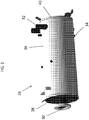
- FIG. 1 Shown in FIG. 1 is a schematic of an embodiment of a refrigerant system 10.
- the refrigerant system 10 includes a compressor 12.
- the present disclosure provides particular benefit for screw compressors, but this disclosure is also beneficial to refrigerant systems 10 having other types of compressors 12.
- An evaporator 14, in some embodiments a flooded style evaporator 14, delivers a flow of refrigerant to the compressor 12 through a suction line 16. From the compressor 12, the refrigerant flows through discharge line 18 to a condenser 20. Compressed, gaseous refrigerant is cooled in the condenser 20, transferred into a liquid phase, and passed through an expansion valve 24 on its way to the evaporator 14 through conduit 22.
- an environment to be cooled such as a fluid flowing through a plurality of evaporator tubes (not shown), is cooled by the refrigerant at the evaporator 14.
- Lubricant usually oil
- the compressor 12 to lubricate bearings and other running surfaces of the compressor 12.
- the oil mixes with the refrigerant operated on by the compressor 12, such that the refrigerant flowing through the system 10 may include a volume of oil entrained therein.
- the system 10 includes an oil separator 26 located, for example, between the compressor 12 and the condenser 20 along line 18.
- the oil separator 26 receives a compressed refrigerant gas and oil entrained therein from the compressor 12 and separates the refrigerant from the oil via, for example, distillation or some other process. Gaseous refrigerant is expelled from the oil separator 26 toward the condenser 20 along line 18, while the oil is directed to an oil sump 28 at the compressor 12 for use in lubrication of the running surfaces of the compressor 12.
- the oil separator 26 is configured as a horizontal oil separator.
- the oil separator 26 has a vapor inlet 30 through which the refrigerant and oil mixture enters the oil separator 26, and also a gas outlet 32 at which the gaseous refrigerant leaves the oil separator 26 and is directed to the condenser 20.
- the oil separator 26 also includes an oil outlet 34 through which liquid oil is returned to the oil sump 28.
- the components of the oil separator 26 are contained in a separator shell 36, which in some embodiments is cylindrical in shape.
- the vapor inlet 30 is located at an inlet plate 38 while the gas outlet 32 is located at or near a second plate 40.
- the gas outlet 32 is located nearer the second plate 40 to the inlet plate 38.
- a muffler 42 is positioned in the oil separator 26.
- the muffler 42 is positioned inside the separator shell 36 at or near the vapor inlet 30, coming from the compressor 12 through a compressor discharge line, to reduce pulsations in the refrigerant and oil mixture.
- the muffler 42 includes a first perforated pipe 44 extending along a separator central axis 46.
- a second perforated pipe 48 is concentric with the first perforated pipe 44 and radially spaced therefrom.
- the first perforated pipe 44 and the second perforated pipe 48 each have a plurality of openings (not shown) therein to allow fluid communication between an internal pathway 52 inside the first perforated pipe 44, an intermediate pathway 54 between the first perforated pipe 44 and the second perforated pipe 48, and an external pathway 56 outside of the second perforated pipe 48.
- one or more baffles 58 are located along the separator central axis 46, to aid in reducing the effects of fluid pulsation entering the oil separator 26.
- the one or more baffles 58 extend radially outwardly from the first perforated pipe 44 to the second perforated pipe 48, with the first perforated pipe 44 defining an inboard radial extent of the one or more baffles 58.
- the one or more baffles 58 extend to the separator shell 36, with the separator shell 36 defining an outboard radial extent of the one or more baffles 58.
- an absorption material layer 60 is located radially outboard of the second perforated pipe 48, between baffles 58 of the one or more baffles 58.
- the absorption material layer 60 is rockwool or fiberglass to absorb pulsation acoustic soundwaves.
- the absorption material layer 60 occupies or fills the external pathway 56 in its entirety.
- a liner 62 is located between the second perforated pipe 48 and the absorption material layer 60.
- the liner 62 is formed from steel woven cloth, which allows the acoustic waves to propagate through the open construction of the liner 62 to be absorbed by the absorption material layer 60, even when the liner 62 is saturated with refrigerant and/or oil during operation of the oil separator 26.
- the muffler 42 including the one or more baffles 58, and the liner 62 of the present disclosure results in a muffler 42 meeting desired performance standards for reducing compressor discharge pulsation across a wide range of operating frequencies, such as 25Hz to 100Hz, making the muffler 42 useful for and compatible with variable speed compressors 12, rather than merely compatible with a fixed-speed compressor, such as prior mufflers.
- the liner 62 has improved transmission loss performance, compared to prior mufflers, when soaked with refrigerant and/or oil during operation of the oil separator 36.
- the reactive function in muffler 42 applies the designed volumes between the first perforated pipe 44 and the second perorated pipe 48 to lower dynamic pressure when absorption material layer 60 soaked with refrigerant and/or oil. Further still, the muffler 42 achieves the improved performance while being integrated into the oil separator 36 and not increasing a footprint or volume occupied by the oil separator 36 and muffler 42 combination.
Landscapes
- Engineering & Computer Science (AREA)
- Physics & Mathematics (AREA)
- Mechanical Engineering (AREA)
- Thermal Sciences (AREA)
- General Engineering & Computer Science (AREA)
- Chemical & Material Sciences (AREA)
- Analytical Chemistry (AREA)
- Power Engineering (AREA)
- Compressor (AREA)
- Applications Or Details Of Rotary Compressors (AREA)
Claims (11)
- Schmiermittelseparator (26), umfassend:eine Hülle (36);einen Dampfeinlass (30), der an einem ersten Ende der Hülle angeordnet ist, um einen Kühlmittel- und Schmiermittelstrom in den Schmiermittelseparator (26) einzulassen;einen Schalldämpfer (42), der in der Hülle angeordnet ist, dadurch gekennzeichnet, dass der Schalldämpfer Folgendes beinhaltet:ein erstes perforiertes Rohr (44), das sich entlang einer Längsachse (46) der Hülle (36) von dem Dampfeinlass (30) erstreckt;ein zweites perforiertes Rohr (48), das radial von dem ersten perforierten Rohr (44) beabstandet ist;eine Absorptionsmaterialschicht (60), die radial außerhalb des zweiten perforierten Rohrs (48) angeordnet ist; undeine schmiermitteldurchlässige Auskleidung (62), die radial zwischen dem zweiten perforierten Rohr (48) und der Absorptionsmaterialschicht (60) angeordnet ist, wobei die schmiermitteldurchlässige Auskleidung (62) eine Schallwellenübertragung von dem zweiten perforierten Rohr (48) zu der Absorptionsmaterialschicht (60) ermöglicht.
- Schmiermittelseparator nach Anspruch 1, ferner umfassend einen oder mehrere Schalldämpfer (58), die sich von dem ersten perforierten Rohr (44) radial nach außen erstrecken, wobei der eine oder die mehreren Schalldämpfer (58) die Absorptionsmaterialschicht (60) positionieren.
- Schmiermittelseparator nach Anspruch 1 oder 2, wobei ein Zwischendurchgang (54), der zwischen dem ersten perforierten Rohr (44) und dem zweiten perforierten Rohr (48) definiert ist, frei von Absorptionsmaterial ist.
- Schmiermittelseparator nach einem der Ansprüche 1-3, wobei die Absorptionsmaterialschicht (60) einen äußeren Durchgang (56), der zwischen der Auskleidung und der Hülle definiert ist, im Wesentlichen ausfüllt.
- Schmiermittelseparator nach einem der Ansprüche 1-4, wobei die Absorptionsmaterialschicht (60) aus einem oder mehreren von Glasfaser oder Steinwolle gebildet ist.
- Schmiermittelseparator nach einem der Ansprüche 1-5, wobei die Auskleidung (62) aus einem oder mehreren von Stahldraht gebildet ist.
- Schmiermittelseparator nach einem der Ansprüche 1-6, ferner umfassend einen Gasauslass (32), der an einem zweiten Ende der Hülle (36) gegenüber dem ersten Ende angeordnet ist, um einen Kühlmittelstrom von dem Schmiermittelseparator (26) abzugeben.
- Schmiermittelseparator nach einem der Ansprüche 1-7, ferner umfassend einen Schmiermittelauslass (34), der in der Hülle (36) angeordnet ist, um einen Schmiermittelstrom von dem Schmiermittelseparator (26) abzugeben.
- Heizungs-, Lüftungs-, Klimaanlagen- und Kühlungssystem, umfassend:einen Verdichter (12), der konfiguriert ist, um einen Kühlmittelstrom dadurch zu verdichten;einen Kondensator (20), der fluidisch an den Verdichter gekoppelt ist, um den Kühlmittelstrom von dem Verdichter aufzunehmen; undden Schmiermittelseparator (26) nach einem der vorangehenden Ansprüche, der konfiguriert ist, um ein Verdichterschmiermittel von dem Kühlmittelstrom zu trennen.
- Heizungs-, Lüftungs-, Klimaanlagen- und Kühlungssystem nach Anspruch 9, wobei der Schmiermittelseparator (26) entlang einer Kühlmittelleitung angeordnet ist, die sich zwischen dem Verdichter (12) und dem Kondensator (20) erstreckt.
- Heizungs-, Lüftungs-, Klimaanlagen- und Kühlungssystem nach Anspruch 9 oder 10, wobei der Verdichter (12) ein Schraubenverdichter mit variabler Geschwindigkeit ist.
Applications Claiming Priority (1)
| Application Number | Priority Date | Filing Date | Title |
|---|---|---|---|
| PCT/IB2016/001782 WO2018091939A1 (en) | 2016-11-15 | 2016-11-15 | Lubricant separator with muffler |
Publications (2)
| Publication Number | Publication Date |
|---|---|
| EP3542109A1 EP3542109A1 (de) | 2019-09-25 |
| EP3542109B1 true EP3542109B1 (de) | 2020-07-08 |
Family
ID=57680427
Family Applications (1)
| Application Number | Title | Priority Date | Filing Date |
|---|---|---|---|
| EP16819653.3A Active EP3542109B1 (de) | 2016-11-15 | 2016-11-15 | Schmiermittelseparator mit schalldämpfer |
Country Status (5)
| Country | Link |
|---|---|
| US (1) | US10907870B2 (de) |
| EP (1) | EP3542109B1 (de) |
| CN (1) | CN109952477B (de) |
| ES (1) | ES2806275T3 (de) |
| WO (1) | WO2018091939A1 (de) |
Families Citing this family (6)
| Publication number | Priority date | Publication date | Assignee | Title |
|---|---|---|---|---|
| CN110906594A (zh) | 2018-09-14 | 2020-03-24 | 开利公司 | 油分离器以及具有该油分离器的空调系统 |
| US11732716B2 (en) * | 2018-12-10 | 2023-08-22 | Carrier Corporation | Modular compressor discharge system |
| CN114502896B (zh) * | 2019-10-04 | 2024-03-29 | 三星电子株式会社 | 空调 |
| CN112325523A (zh) * | 2020-11-27 | 2021-02-05 | 珠海格力电器股份有限公司 | 一种油气分离器及具有其的空调系统 |
| CN113991484B (zh) * | 2021-11-04 | 2023-12-29 | 武汉市工程科学技术研究院 | 一种防潮室外低压交流配电柜 |
| CN117433189B (zh) * | 2023-11-30 | 2024-06-07 | 浙江红五环机械股份有限公司 | 一种用于双全封闭螺杆式压缩机油平衡辅助回油装置 |
Family Cites Families (27)
| Publication number | Priority date | Publication date | Assignee | Title |
|---|---|---|---|---|
| US3070977A (en) * | 1961-03-31 | 1963-01-01 | Heat X Inc | Refrigeration system, including oil separator and muffler unit and oil return arrangement |
| CA1155400A (en) | 1981-02-09 | 1983-10-18 | George H. Williams | Muffler |
| US4957517A (en) * | 1989-04-28 | 1990-09-18 | American Standard Inc. | Sound attenuating liquid-gas separator |
| US5214937A (en) * | 1991-10-28 | 1993-06-01 | Carrier Corporation | Integral oil separator and muffler |
| US5350888A (en) | 1992-05-01 | 1994-09-27 | Tennessee Gas Pipeline Company | Broad band low frequency passive muffler |
| CN2147356Y (zh) | 1992-10-27 | 1993-11-24 | 天津碱厂 | 螺杆压缩机出口消声器 |
| US5705777A (en) * | 1995-10-20 | 1998-01-06 | Carrier Corporation | Refrigeration compressor muffler |
| US6131405A (en) * | 1997-12-03 | 2000-10-17 | Parker-Hannifin Corporation | Discharge separator and muffler for refrigeration, air conditioning and heat pump systems |
| DE29904410U1 (de) | 1999-03-10 | 2000-07-20 | GHH-RAND Schraubenkompressoren GmbH & Co. KG, 46145 Oberhausen | Schraubenkompressor |
| US6799657B2 (en) | 2002-10-02 | 2004-10-05 | Carrier Corporation | Absorptive/reactive muffler for variable speed compressors |
| US7100737B2 (en) | 2003-07-28 | 2006-09-05 | Carrier Corporation | Muffler for noise reduction |
| US6976833B2 (en) | 2003-11-17 | 2005-12-20 | Carrier Corporation | Compressor discharge chamber with baffle plate |
| DE10359032A1 (de) | 2003-12-15 | 2005-07-14 | Bitzer Kühlmaschinenbau Gmbh | Schraubenverdichter |
| US20060065478A1 (en) | 2004-09-30 | 2006-03-30 | Rockwell David M | Compressor sound suppression |
| US7121814B2 (en) | 2004-09-30 | 2006-10-17 | Carrier Corporation | Compressor sound suppression |
| US8021126B2 (en) | 2004-10-20 | 2011-09-20 | Carrier Corporation | Compressor sound suppression |
| EP1875049B1 (de) | 2005-04-11 | 2012-08-15 | Carrier Corporation | Schalldämpfer für verdichter |
| EP1715189B1 (de) | 2005-04-22 | 2013-12-04 | Kaeser Kompressoren AG | Schalldämpfer ausgebildet und bestimmt für einen Kompressor |
| CN101228401B (zh) * | 2005-05-31 | 2014-06-18 | 开利公司 | 用于降低油分离器所输出的噪声级的方法和设备 |
| ES2355919T3 (es) * | 2005-05-31 | 2011-04-01 | Carrier Corporation | Métodos y aparatos para reducir el nivel de ruido producido por un separador de aceite. |
| TW200912222A (en) * | 2007-07-12 | 2009-03-16 | Johnson Controls Tech Co | Oil separator |
| ES2629981T3 (es) | 2007-10-01 | 2017-08-17 | Carrier Corporation | Amortiguador de pulsación para compresor de tornillo |
| JP5112152B2 (ja) * | 2008-04-14 | 2013-01-09 | 株式会社神戸製鋼所 | 潤滑液分離装置 |
| CN201221882Y (zh) * | 2008-05-23 | 2009-04-15 | 上海富田空调冷冻设备有限公司 | 制冷机用油分离器 |
| DE102008036317A1 (de) | 2008-07-29 | 2010-02-25 | Bitzer Kühlmaschinenbau Gmbh | Schraubenverdichter |
| DE102012102349A1 (de) | 2012-03-20 | 2013-09-26 | Bitzer Kühlmaschinenbau Gmbh | Kältemittelverdichter |
| CN103134249B (zh) * | 2013-03-15 | 2014-12-03 | 浙江青风环境股份有限公司 | 高效油分离器 |
-
2016
- 2016-11-15 WO PCT/IB2016/001782 patent/WO2018091939A1/en not_active Ceased
- 2016-11-15 CN CN201680090840.9A patent/CN109952477B/zh active Active
- 2016-11-15 US US16/461,077 patent/US10907870B2/en active Active
- 2016-11-15 ES ES16819653T patent/ES2806275T3/es active Active
- 2016-11-15 EP EP16819653.3A patent/EP3542109B1/de active Active
Non-Patent Citations (1)
| Title |
|---|
| None * |
Also Published As
| Publication number | Publication date |
|---|---|
| WO2018091939A1 (en) | 2018-05-24 |
| EP3542109A1 (de) | 2019-09-25 |
| CN109952477A (zh) | 2019-06-28 |
| US20190277547A1 (en) | 2019-09-12 |
| CN109952477B (zh) | 2021-05-25 |
| US10907870B2 (en) | 2021-02-02 |
| ES2806275T3 (es) | 2021-02-17 |
Similar Documents
| Publication | Publication Date | Title |
|---|---|---|
| EP3542109B1 (de) | Schmiermittelseparator mit schalldämpfer | |
| JPH02301696A (ja) | 音減衰型液体とガスの分離装置 | |
| CN112160908B (zh) | 泵体组件、压缩机和空调器 | |
| US20080034784A1 (en) | Combined oil separator and muffler for refrigerant compressor | |
| CN204285910U (zh) | 一种压缩机用储液器 | |
| CN113958503B (zh) | 压缩机及制冷设备 | |
| US10890188B2 (en) | Compressor noise reduction | |
| AU2005316878B2 (en) | Refrigerant/oil separator | |
| CN114017335A (zh) | 压缩机与制冷设备 | |
| JP5787564B2 (ja) | 気液分離および油分離が可能な分離器 | |
| RU2664274C1 (ru) | Центробежный компрессор и водоохладительный агрегат, оборудованный таким же центробежным компрессором | |
| CN112556254B (zh) | 油分离器、空调系统 | |
| CN112665202A (zh) | 空调系统 | |
| US8596088B2 (en) | Oil separator for air conditioner | |
| CN219932448U (zh) | 压缩机和制冷设备 | |
| KR102336280B1 (ko) | 트윈 로터리 압축기 및 냉동 사이클 장치 | |
| WO2021074804A1 (en) | Screw compressor | |
| KR20030066044A (ko) | 압축기 내장형 오일 분리기 | |
| CN217979392U (zh) | 油分离器和空调系统 | |
| EP4045799B1 (de) | Schraubenverdichter | |
| CN117307491B (zh) | 壳体部件、电动压缩机、空调系统及车辆 | |
| JPH08312563A (ja) | 回転式圧縮機 | |
| EP2988073B1 (de) | Pulsationsdämpfer und Kühlkreislauf mit einem Pulsationsdämpfer | |
| CN118911987A (zh) | 压缩机和制冷设备 | |
| CN118030528A (zh) | 压缩机 |
Legal Events
| Date | Code | Title | Description |
|---|---|---|---|
| STAA | Information on the status of an ep patent application or granted ep patent |
Free format text: STATUS: UNKNOWN |
|
| STAA | Information on the status of an ep patent application or granted ep patent |
Free format text: STATUS: THE INTERNATIONAL PUBLICATION HAS BEEN MADE |
|
| PUAI | Public reference made under article 153(3) epc to a published international application that has entered the european phase |
Free format text: ORIGINAL CODE: 0009012 |
|
| STAA | Information on the status of an ep patent application or granted ep patent |
Free format text: STATUS: REQUEST FOR EXAMINATION WAS MADE |
|
| 17P | Request for examination filed |
Effective date: 20190523 |
|
| AK | Designated contracting states |
Kind code of ref document: A1 Designated state(s): AL AT BE BG CH CY CZ DE DK EE ES FI FR GB GR HR HU IE IS IT LI LT LU LV MC MK MT NL NO PL PT RO RS SE SI SK SM TR |
|
| AX | Request for extension of the european patent |
Extension state: BA ME |
|
| DAV | Request for validation of the european patent (deleted) | ||
| DAX | Request for extension of the european patent (deleted) | ||
| GRAP | Despatch of communication of intention to grant a patent |
Free format text: ORIGINAL CODE: EPIDOSNIGR1 |
|
| STAA | Information on the status of an ep patent application or granted ep patent |
Free format text: STATUS: GRANT OF PATENT IS INTENDED |
|
| GRAS | Grant fee paid |
Free format text: ORIGINAL CODE: EPIDOSNIGR3 |
|
| INTG | Intention to grant announced |
Effective date: 20200326 |
|
| GRAA | (expected) grant |
Free format text: ORIGINAL CODE: 0009210 |
|
| STAA | Information on the status of an ep patent application or granted ep patent |
Free format text: STATUS: THE PATENT HAS BEEN GRANTED |
|
| AK | Designated contracting states |
Kind code of ref document: B1 Designated state(s): AL AT BE BG CH CY CZ DE DK EE ES FI FR GB GR HR HU IE IS IT LI LT LU LV MC MK MT NL NO PL PT RO RS SE SI SK SM TR |
|
| REG | Reference to a national code |
Ref country code: CH Ref legal event code: EP Ref country code: AT Ref legal event code: REF Ref document number: 1288889 Country of ref document: AT Kind code of ref document: T Effective date: 20200715 |
|
| REG | Reference to a national code |
Ref country code: DE Ref legal event code: R096 Ref document number: 602016039677 Country of ref document: DE |
|
| REG | Reference to a national code |
Ref country code: IE Ref legal event code: FG4D |
|
| REG | Reference to a national code |
Ref country code: NL Ref legal event code: FP |
|
| REG | Reference to a national code |
Ref country code: LT Ref legal event code: MG4D |
|
| REG | Reference to a national code |
Ref country code: AT Ref legal event code: MK05 Ref document number: 1288889 Country of ref document: AT Kind code of ref document: T Effective date: 20200708 |
|
| PG25 | Lapsed in a contracting state [announced via postgrant information from national office to epo] |
Ref country code: NO Free format text: LAPSE BECAUSE OF FAILURE TO SUBMIT A TRANSLATION OF THE DESCRIPTION OR TO PAY THE FEE WITHIN THE PRESCRIBED TIME-LIMIT Effective date: 20201008 Ref country code: PT Free format text: LAPSE BECAUSE OF FAILURE TO SUBMIT A TRANSLATION OF THE DESCRIPTION OR TO PAY THE FEE WITHIN THE PRESCRIBED TIME-LIMIT Effective date: 20201109 Ref country code: BG Free format text: LAPSE BECAUSE OF FAILURE TO SUBMIT A TRANSLATION OF THE DESCRIPTION OR TO PAY THE FEE WITHIN THE PRESCRIBED TIME-LIMIT Effective date: 20201008 Ref country code: LT Free format text: LAPSE BECAUSE OF FAILURE TO SUBMIT A TRANSLATION OF THE DESCRIPTION OR TO PAY THE FEE WITHIN THE PRESCRIBED TIME-LIMIT Effective date: 20200708 Ref country code: HR Free format text: LAPSE BECAUSE OF FAILURE TO SUBMIT A TRANSLATION OF THE DESCRIPTION OR TO PAY THE FEE WITHIN THE PRESCRIBED TIME-LIMIT Effective date: 20200708 Ref country code: AT Free format text: LAPSE BECAUSE OF FAILURE TO SUBMIT A TRANSLATION OF THE DESCRIPTION OR TO PAY THE FEE WITHIN THE PRESCRIBED TIME-LIMIT Effective date: 20200708 Ref country code: SE Free format text: LAPSE BECAUSE OF FAILURE TO SUBMIT A TRANSLATION OF THE DESCRIPTION OR TO PAY THE FEE WITHIN THE PRESCRIBED TIME-LIMIT Effective date: 20200708 Ref country code: GR Free format text: LAPSE BECAUSE OF FAILURE TO SUBMIT A TRANSLATION OF THE DESCRIPTION OR TO PAY THE FEE WITHIN THE PRESCRIBED TIME-LIMIT Effective date: 20201009 Ref country code: FI Free format text: LAPSE BECAUSE OF FAILURE TO SUBMIT A TRANSLATION OF THE DESCRIPTION OR TO PAY THE FEE WITHIN THE PRESCRIBED TIME-LIMIT Effective date: 20200708 |
|
| REG | Reference to a national code |
Ref country code: ES Ref legal event code: FG2A Ref document number: 2806275 Country of ref document: ES Kind code of ref document: T3 Effective date: 20210217 |
|
| PG25 | Lapsed in a contracting state [announced via postgrant information from national office to epo] |
Ref country code: RS Free format text: LAPSE BECAUSE OF FAILURE TO SUBMIT A TRANSLATION OF THE DESCRIPTION OR TO PAY THE FEE WITHIN THE PRESCRIBED TIME-LIMIT Effective date: 20200708 Ref country code: PL Free format text: LAPSE BECAUSE OF FAILURE TO SUBMIT A TRANSLATION OF THE DESCRIPTION OR TO PAY THE FEE WITHIN THE PRESCRIBED TIME-LIMIT Effective date: 20200708 Ref country code: LV Free format text: LAPSE BECAUSE OF FAILURE TO SUBMIT A TRANSLATION OF THE DESCRIPTION OR TO PAY THE FEE WITHIN THE PRESCRIBED TIME-LIMIT Effective date: 20200708 Ref country code: IS Free format text: LAPSE BECAUSE OF FAILURE TO SUBMIT A TRANSLATION OF THE DESCRIPTION OR TO PAY THE FEE WITHIN THE PRESCRIBED TIME-LIMIT Effective date: 20201108 |
|
| REG | Reference to a national code |
Ref country code: DE Ref legal event code: R097 Ref document number: 602016039677 Country of ref document: DE |
|
| PG25 | Lapsed in a contracting state [announced via postgrant information from national office to epo] |
Ref country code: CZ Free format text: LAPSE BECAUSE OF FAILURE TO SUBMIT A TRANSLATION OF THE DESCRIPTION OR TO PAY THE FEE WITHIN THE PRESCRIBED TIME-LIMIT Effective date: 20200708 Ref country code: DK Free format text: LAPSE BECAUSE OF FAILURE TO SUBMIT A TRANSLATION OF THE DESCRIPTION OR TO PAY THE FEE WITHIN THE PRESCRIBED TIME-LIMIT Effective date: 20200708 Ref country code: RO Free format text: LAPSE BECAUSE OF FAILURE TO SUBMIT A TRANSLATION OF THE DESCRIPTION OR TO PAY THE FEE WITHIN THE PRESCRIBED TIME-LIMIT Effective date: 20200708 Ref country code: SM Free format text: LAPSE BECAUSE OF FAILURE TO SUBMIT A TRANSLATION OF THE DESCRIPTION OR TO PAY THE FEE WITHIN THE PRESCRIBED TIME-LIMIT Effective date: 20200708 Ref country code: EE Free format text: LAPSE BECAUSE OF FAILURE TO SUBMIT A TRANSLATION OF THE DESCRIPTION OR TO PAY THE FEE WITHIN THE PRESCRIBED TIME-LIMIT Effective date: 20200708 |
|
| PLBE | No opposition filed within time limit |
Free format text: ORIGINAL CODE: 0009261 |
|
| STAA | Information on the status of an ep patent application or granted ep patent |
Free format text: STATUS: NO OPPOSITION FILED WITHIN TIME LIMIT |
|
| PG25 | Lapsed in a contracting state [announced via postgrant information from national office to epo] |
Ref country code: AL Free format text: LAPSE BECAUSE OF FAILURE TO SUBMIT A TRANSLATION OF THE DESCRIPTION OR TO PAY THE FEE WITHIN THE PRESCRIBED TIME-LIMIT Effective date: 20200708 |
|
| 26N | No opposition filed |
Effective date: 20210409 |
|
| PG25 | Lapsed in a contracting state [announced via postgrant information from national office to epo] |
Ref country code: MC Free format text: LAPSE BECAUSE OF FAILURE TO SUBMIT A TRANSLATION OF THE DESCRIPTION OR TO PAY THE FEE WITHIN THE PRESCRIBED TIME-LIMIT Effective date: 20200708 Ref country code: SK Free format text: LAPSE BECAUSE OF FAILURE TO SUBMIT A TRANSLATION OF THE DESCRIPTION OR TO PAY THE FEE WITHIN THE PRESCRIBED TIME-LIMIT Effective date: 20200708 |
|
| REG | Reference to a national code |
Ref country code: CH Ref legal event code: PL |
|
| GBPC | Gb: european patent ceased through non-payment of renewal fee |
Effective date: 20201115 |
|
| PG25 | Lapsed in a contracting state [announced via postgrant information from national office to epo] |
Ref country code: LU Free format text: LAPSE BECAUSE OF NON-PAYMENT OF DUE FEES Effective date: 20201115 |
|
| PG25 | Lapsed in a contracting state [announced via postgrant information from national office to epo] |
Ref country code: LI Free format text: LAPSE BECAUSE OF NON-PAYMENT OF DUE FEES Effective date: 20201130 Ref country code: SI Free format text: LAPSE BECAUSE OF FAILURE TO SUBMIT A TRANSLATION OF THE DESCRIPTION OR TO PAY THE FEE WITHIN THE PRESCRIBED TIME-LIMIT Effective date: 20200708 Ref country code: CH Free format text: LAPSE BECAUSE OF NON-PAYMENT OF DUE FEES Effective date: 20201130 |
|
| PG25 | Lapsed in a contracting state [announced via postgrant information from national office to epo] |
Ref country code: IE Free format text: LAPSE BECAUSE OF NON-PAYMENT OF DUE FEES Effective date: 20201115 |
|
| PG25 | Lapsed in a contracting state [announced via postgrant information from national office to epo] |
Ref country code: GB Free format text: LAPSE BECAUSE OF NON-PAYMENT OF DUE FEES Effective date: 20201115 |
|
| PG25 | Lapsed in a contracting state [announced via postgrant information from national office to epo] |
Ref country code: IS Free format text: LAPSE BECAUSE OF FAILURE TO SUBMIT A TRANSLATION OF THE DESCRIPTION OR TO PAY THE FEE WITHIN THE PRESCRIBED TIME-LIMIT Effective date: 20201108 Ref country code: TR Free format text: LAPSE BECAUSE OF FAILURE TO SUBMIT A TRANSLATION OF THE DESCRIPTION OR TO PAY THE FEE WITHIN THE PRESCRIBED TIME-LIMIT Effective date: 20200708 Ref country code: MT Free format text: LAPSE BECAUSE OF FAILURE TO SUBMIT A TRANSLATION OF THE DESCRIPTION OR TO PAY THE FEE WITHIN THE PRESCRIBED TIME-LIMIT Effective date: 20200708 Ref country code: CY Free format text: LAPSE BECAUSE OF FAILURE TO SUBMIT A TRANSLATION OF THE DESCRIPTION OR TO PAY THE FEE WITHIN THE PRESCRIBED TIME-LIMIT Effective date: 20200708 |
|
| PG25 | Lapsed in a contracting state [announced via postgrant information from national office to epo] |
Ref country code: MK Free format text: LAPSE BECAUSE OF FAILURE TO SUBMIT A TRANSLATION OF THE DESCRIPTION OR TO PAY THE FEE WITHIN THE PRESCRIBED TIME-LIMIT Effective date: 20200708 |
|
| P01 | Opt-out of the competence of the unified patent court (upc) registered |
Effective date: 20230527 |
|
| PGFP | Annual fee paid to national office [announced via postgrant information from national office to epo] |
Ref country code: NL Payment date: 20241022 Year of fee payment: 9 |
|
| PGFP | Annual fee paid to national office [announced via postgrant information from national office to epo] |
Ref country code: BE Payment date: 20241022 Year of fee payment: 9 |
|
| PGFP | Annual fee paid to national office [announced via postgrant information from national office to epo] |
Ref country code: IT Payment date: 20241022 Year of fee payment: 9 Ref country code: ES Payment date: 20241202 Year of fee payment: 9 |
|
| PGFP | Annual fee paid to national office [announced via postgrant information from national office to epo] |
Ref country code: DE Payment date: 20251022 Year of fee payment: 10 |
|
| PGFP | Annual fee paid to national office [announced via postgrant information from national office to epo] |
Ref country code: FR Payment date: 20251022 Year of fee payment: 10 |