EP3543080A1 - Target clutch torque-based creep control system for automatic transmission of heavy truck - Google Patents
Target clutch torque-based creep control system for automatic transmission of heavy truck Download PDFInfo
- Publication number
- EP3543080A1 EP3543080A1 EP17872404.3A EP17872404A EP3543080A1 EP 3543080 A1 EP3543080 A1 EP 3543080A1 EP 17872404 A EP17872404 A EP 17872404A EP 3543080 A1 EP3543080 A1 EP 3543080A1
- Authority
- EP
- European Patent Office
- Prior art keywords
- clutch
- creep control
- state
- vehicle
- tcu
- Prior art date
- Legal status (The legal status is an assumption and is not a legal conclusion. Google has not performed a legal analysis and makes no representation as to the accuracy of the status listed.)
- Granted
Links
Images





Classifications
-
- B—PERFORMING OPERATIONS; TRANSPORTING
- B60—VEHICLES IN GENERAL
- B60W—CONJOINT CONTROL OF VEHICLE SUB-UNITS OF DIFFERENT TYPE OR DIFFERENT FUNCTION; CONTROL SYSTEMS SPECIALLY ADAPTED FOR HYBRID VEHICLES; ROAD VEHICLE DRIVE CONTROL SYSTEMS FOR PURPOSES NOT RELATED TO THE CONTROL OF A PARTICULAR SUB-UNIT
- B60W30/00—Purposes of road vehicle drive control systems not related to the control of a particular sub-unit, e.g. of systems using conjoint control of vehicle sub-units
- B60W30/18—Propelling the vehicle
- B60W30/184—Preventing damage resulting from overload or excessive wear of the driveline
- B60W30/186—Preventing damage resulting from overload or excessive wear of the driveline excessive wear or burn out of friction elements, e.g. clutches
-
- B—PERFORMING OPERATIONS; TRANSPORTING
- B60—VEHICLES IN GENERAL
- B60W—CONJOINT CONTROL OF VEHICLE SUB-UNITS OF DIFFERENT TYPE OR DIFFERENT FUNCTION; CONTROL SYSTEMS SPECIALLY ADAPTED FOR HYBRID VEHICLES; ROAD VEHICLE DRIVE CONTROL SYSTEMS FOR PURPOSES NOT RELATED TO THE CONTROL OF A PARTICULAR SUB-UNIT
- B60W10/00—Conjoint control of vehicle sub-units of different type or different function
- B60W10/02—Conjoint control of vehicle sub-units of different type or different function including control of driveline clutches
-
- B—PERFORMING OPERATIONS; TRANSPORTING
- B60—VEHICLES IN GENERAL
- B60W—CONJOINT CONTROL OF VEHICLE SUB-UNITS OF DIFFERENT TYPE OR DIFFERENT FUNCTION; CONTROL SYSTEMS SPECIALLY ADAPTED FOR HYBRID VEHICLES; ROAD VEHICLE DRIVE CONTROL SYSTEMS FOR PURPOSES NOT RELATED TO THE CONTROL OF A PARTICULAR SUB-UNIT
- B60W10/00—Conjoint control of vehicle sub-units of different type or different function
- B60W10/04—Conjoint control of vehicle sub-units of different type or different function including control of propulsion units
- B60W10/06—Conjoint control of vehicle sub-units of different type or different function including control of propulsion units including control of combustion engines
-
- B—PERFORMING OPERATIONS; TRANSPORTING
- B60—VEHICLES IN GENERAL
- B60W—CONJOINT CONTROL OF VEHICLE SUB-UNITS OF DIFFERENT TYPE OR DIFFERENT FUNCTION; CONTROL SYSTEMS SPECIALLY ADAPTED FOR HYBRID VEHICLES; ROAD VEHICLE DRIVE CONTROL SYSTEMS FOR PURPOSES NOT RELATED TO THE CONTROL OF A PARTICULAR SUB-UNIT
- B60W10/00—Conjoint control of vehicle sub-units of different type or different function
- B60W10/10—Conjoint control of vehicle sub-units of different type or different function including control of change-speed gearings
-
- B—PERFORMING OPERATIONS; TRANSPORTING
- B60—VEHICLES IN GENERAL
- B60W—CONJOINT CONTROL OF VEHICLE SUB-UNITS OF DIFFERENT TYPE OR DIFFERENT FUNCTION; CONTROL SYSTEMS SPECIALLY ADAPTED FOR HYBRID VEHICLES; ROAD VEHICLE DRIVE CONTROL SYSTEMS FOR PURPOSES NOT RELATED TO THE CONTROL OF A PARTICULAR SUB-UNIT
- B60W30/00—Purposes of road vehicle drive control systems not related to the control of a particular sub-unit, e.g. of systems using conjoint control of vehicle sub-units
- B60W30/18—Propelling the vehicle
- B60W30/18009—Propelling the vehicle related to particular drive situations
- B60W30/18063—Creeping
-
- B—PERFORMING OPERATIONS; TRANSPORTING
- B60—VEHICLES IN GENERAL
- B60W—CONJOINT CONTROL OF VEHICLE SUB-UNITS OF DIFFERENT TYPE OR DIFFERENT FUNCTION; CONTROL SYSTEMS SPECIALLY ADAPTED FOR HYBRID VEHICLES; ROAD VEHICLE DRIVE CONTROL SYSTEMS FOR PURPOSES NOT RELATED TO THE CONTROL OF A PARTICULAR SUB-UNIT
- B60W50/00—Details of control systems for road vehicle drive control not related to the control of a particular sub-unit, e.g. process diagnostic or vehicle driver interfaces
- B60W50/08—Interaction between the driver and the control system
- B60W50/14—Means for informing the driver, warning the driver or prompting a driver intervention
-
- F—MECHANICAL ENGINEERING; LIGHTING; HEATING; WEAPONS; BLASTING
- F16—ENGINEERING ELEMENTS AND UNITS; GENERAL MEASURES FOR PRODUCING AND MAINTAINING EFFECTIVE FUNCTIONING OF MACHINES OR INSTALLATIONS; THERMAL INSULATION IN GENERAL
- F16D—COUPLINGS FOR TRANSMITTING ROTATION; CLUTCHES; BRAKES
- F16D48/00—External control of clutches
- F16D48/06—Control by electric or electronic means, e.g. of fluid pressure
-
- F—MECHANICAL ENGINEERING; LIGHTING; HEATING; WEAPONS; BLASTING
- F16—ENGINEERING ELEMENTS AND UNITS; GENERAL MEASURES FOR PRODUCING AND MAINTAINING EFFECTIVE FUNCTIONING OF MACHINES OR INSTALLATIONS; THERMAL INSULATION IN GENERAL
- F16H—GEARING
- F16H61/00—Control functions within control units of change-speed- or reversing-gearings for conveying rotary motion ; Control of exclusively fluid gearing, friction gearing, gearings with endless flexible members or other particular types of gearing
- F16H61/02—Control functions within control units of change-speed- or reversing-gearings for conveying rotary motion ; Control of exclusively fluid gearing, friction gearing, gearings with endless flexible members or other particular types of gearing characterised by the signals used
- F16H61/0202—Control functions within control units of change-speed- or reversing-gearings for conveying rotary motion ; Control of exclusively fluid gearing, friction gearing, gearings with endless flexible members or other particular types of gearing characterised by the signals used the signals being electric
- F16H61/0204—Control functions within control units of change-speed- or reversing-gearings for conveying rotary motion ; Control of exclusively fluid gearing, friction gearing, gearings with endless flexible members or other particular types of gearing characterised by the signals used the signals being electric for gearshift control, e.g. control functions for performing shifting or generation of shift signal
- F16H61/0213—Control functions within control units of change-speed- or reversing-gearings for conveying rotary motion ; Control of exclusively fluid gearing, friction gearing, gearings with endless flexible members or other particular types of gearing characterised by the signals used the signals being electric for gearshift control, e.g. control functions for performing shifting or generation of shift signal characterised by the method for generating shift signals
-
- F—MECHANICAL ENGINEERING; LIGHTING; HEATING; WEAPONS; BLASTING
- F16—ENGINEERING ELEMENTS AND UNITS; GENERAL MEASURES FOR PRODUCING AND MAINTAINING EFFECTIVE FUNCTIONING OF MACHINES OR INSTALLATIONS; THERMAL INSULATION IN GENERAL
- F16H—GEARING
- F16H61/00—Control functions within control units of change-speed- or reversing-gearings for conveying rotary motion ; Control of exclusively fluid gearing, friction gearing, gearings with endless flexible members or other particular types of gearing
- F16H61/12—Detecting malfunction or potential malfunction, e.g. fail safe ; Circumventing or fixing failures
-
- B—PERFORMING OPERATIONS; TRANSPORTING
- B60—VEHICLES IN GENERAL
- B60W—CONJOINT CONTROL OF VEHICLE SUB-UNITS OF DIFFERENT TYPE OR DIFFERENT FUNCTION; CONTROL SYSTEMS SPECIALLY ADAPTED FOR HYBRID VEHICLES; ROAD VEHICLE DRIVE CONTROL SYSTEMS FOR PURPOSES NOT RELATED TO THE CONTROL OF A PARTICULAR SUB-UNIT
- B60W50/00—Details of control systems for road vehicle drive control not related to the control of a particular sub-unit, e.g. process diagnostic or vehicle driver interfaces
- B60W2050/0001—Details of the control system
- B60W2050/0002—Automatic control, details of type of controller or control system architecture
- B60W2050/0008—Feedback, closed loop systems or details of feedback error signal
-
- B—PERFORMING OPERATIONS; TRANSPORTING
- B60—VEHICLES IN GENERAL
- B60W—CONJOINT CONTROL OF VEHICLE SUB-UNITS OF DIFFERENT TYPE OR DIFFERENT FUNCTION; CONTROL SYSTEMS SPECIALLY ADAPTED FOR HYBRID VEHICLES; ROAD VEHICLE DRIVE CONTROL SYSTEMS FOR PURPOSES NOT RELATED TO THE CONTROL OF A PARTICULAR SUB-UNIT
- B60W50/00—Details of control systems for road vehicle drive control not related to the control of a particular sub-unit, e.g. process diagnostic or vehicle driver interfaces
- B60W50/08—Interaction between the driver and the control system
- B60W50/14—Means for informing the driver, warning the driver or prompting a driver intervention
- B60W2050/143—Alarm means
-
- B—PERFORMING OPERATIONS; TRANSPORTING
- B60—VEHICLES IN GENERAL
- B60W—CONJOINT CONTROL OF VEHICLE SUB-UNITS OF DIFFERENT TYPE OR DIFFERENT FUNCTION; CONTROL SYSTEMS SPECIALLY ADAPTED FOR HYBRID VEHICLES; ROAD VEHICLE DRIVE CONTROL SYSTEMS FOR PURPOSES NOT RELATED TO THE CONTROL OF A PARTICULAR SUB-UNIT
- B60W2300/00—Indexing codes relating to the type of vehicle
- B60W2300/12—Trucks; Load vehicles
- B60W2300/125—Heavy duty trucks
-
- B—PERFORMING OPERATIONS; TRANSPORTING
- B60—VEHICLES IN GENERAL
- B60W—CONJOINT CONTROL OF VEHICLE SUB-UNITS OF DIFFERENT TYPE OR DIFFERENT FUNCTION; CONTROL SYSTEMS SPECIALLY ADAPTED FOR HYBRID VEHICLES; ROAD VEHICLE DRIVE CONTROL SYSTEMS FOR PURPOSES NOT RELATED TO THE CONTROL OF A PARTICULAR SUB-UNIT
- B60W2510/00—Input parameters relating to a particular sub-units
- B60W2510/02—Clutches
- B60W2510/0208—Clutch engagement state, e.g. engaged or disengaged
-
- B—PERFORMING OPERATIONS; TRANSPORTING
- B60—VEHICLES IN GENERAL
- B60W—CONJOINT CONTROL OF VEHICLE SUB-UNITS OF DIFFERENT TYPE OR DIFFERENT FUNCTION; CONTROL SYSTEMS SPECIALLY ADAPTED FOR HYBRID VEHICLES; ROAD VEHICLE DRIVE CONTROL SYSTEMS FOR PURPOSES NOT RELATED TO THE CONTROL OF A PARTICULAR SUB-UNIT
- B60W2510/00—Input parameters relating to a particular sub-units
- B60W2510/02—Clutches
- B60W2510/0208—Clutch engagement state, e.g. engaged or disengaged
- B60W2510/0225—Clutch actuator position
-
- B—PERFORMING OPERATIONS; TRANSPORTING
- B60—VEHICLES IN GENERAL
- B60W—CONJOINT CONTROL OF VEHICLE SUB-UNITS OF DIFFERENT TYPE OR DIFFERENT FUNCTION; CONTROL SYSTEMS SPECIALLY ADAPTED FOR HYBRID VEHICLES; ROAD VEHICLE DRIVE CONTROL SYSTEMS FOR PURPOSES NOT RELATED TO THE CONTROL OF A PARTICULAR SUB-UNIT
- B60W2510/00—Input parameters relating to a particular sub-units
- B60W2510/02—Clutches
- B60W2510/0241—Clutch slip, i.e. difference between input and output speeds
-
- B—PERFORMING OPERATIONS; TRANSPORTING
- B60—VEHICLES IN GENERAL
- B60W—CONJOINT CONTROL OF VEHICLE SUB-UNITS OF DIFFERENT TYPE OR DIFFERENT FUNCTION; CONTROL SYSTEMS SPECIALLY ADAPTED FOR HYBRID VEHICLES; ROAD VEHICLE DRIVE CONTROL SYSTEMS FOR PURPOSES NOT RELATED TO THE CONTROL OF A PARTICULAR SUB-UNIT
- B60W2510/00—Input parameters relating to a particular sub-units
- B60W2510/02—Clutches
- B60W2510/0275—Clutch torque
-
- B—PERFORMING OPERATIONS; TRANSPORTING
- B60—VEHICLES IN GENERAL
- B60W—CONJOINT CONTROL OF VEHICLE SUB-UNITS OF DIFFERENT TYPE OR DIFFERENT FUNCTION; CONTROL SYSTEMS SPECIALLY ADAPTED FOR HYBRID VEHICLES; ROAD VEHICLE DRIVE CONTROL SYSTEMS FOR PURPOSES NOT RELATED TO THE CONTROL OF A PARTICULAR SUB-UNIT
- B60W2510/00—Input parameters relating to a particular sub-units
- B60W2510/02—Clutches
- B60W2510/0291—Clutch temperature
-
- B—PERFORMING OPERATIONS; TRANSPORTING
- B60—VEHICLES IN GENERAL
- B60W—CONJOINT CONTROL OF VEHICLE SUB-UNITS OF DIFFERENT TYPE OR DIFFERENT FUNCTION; CONTROL SYSTEMS SPECIALLY ADAPTED FOR HYBRID VEHICLES; ROAD VEHICLE DRIVE CONTROL SYSTEMS FOR PURPOSES NOT RELATED TO THE CONTROL OF A PARTICULAR SUB-UNIT
- B60W2510/00—Input parameters relating to a particular sub-units
- B60W2510/06—Combustion engines, Gas turbines
- B60W2510/0638—Engine speed
-
- B—PERFORMING OPERATIONS; TRANSPORTING
- B60—VEHICLES IN GENERAL
- B60W—CONJOINT CONTROL OF VEHICLE SUB-UNITS OF DIFFERENT TYPE OR DIFFERENT FUNCTION; CONTROL SYSTEMS SPECIALLY ADAPTED FOR HYBRID VEHICLES; ROAD VEHICLE DRIVE CONTROL SYSTEMS FOR PURPOSES NOT RELATED TO THE CONTROL OF A PARTICULAR SUB-UNIT
- B60W2510/00—Input parameters relating to a particular sub-units
- B60W2510/10—Change speed gearings
- B60W2510/1005—Transmission ratio engaged
-
- B—PERFORMING OPERATIONS; TRANSPORTING
- B60—VEHICLES IN GENERAL
- B60W—CONJOINT CONTROL OF VEHICLE SUB-UNITS OF DIFFERENT TYPE OR DIFFERENT FUNCTION; CONTROL SYSTEMS SPECIALLY ADAPTED FOR HYBRID VEHICLES; ROAD VEHICLE DRIVE CONTROL SYSTEMS FOR PURPOSES NOT RELATED TO THE CONTROL OF A PARTICULAR SUB-UNIT
- B60W2510/00—Input parameters relating to a particular sub-units
- B60W2510/10—Change speed gearings
- B60W2510/1015—Input shaft speed, e.g. turbine speed
-
- B—PERFORMING OPERATIONS; TRANSPORTING
- B60—VEHICLES IN GENERAL
- B60W—CONJOINT CONTROL OF VEHICLE SUB-UNITS OF DIFFERENT TYPE OR DIFFERENT FUNCTION; CONTROL SYSTEMS SPECIALLY ADAPTED FOR HYBRID VEHICLES; ROAD VEHICLE DRIVE CONTROL SYSTEMS FOR PURPOSES NOT RELATED TO THE CONTROL OF A PARTICULAR SUB-UNIT
- B60W2510/00—Input parameters relating to a particular sub-units
- B60W2510/10—Change speed gearings
- B60W2510/104—Output speed
-
- B—PERFORMING OPERATIONS; TRANSPORTING
- B60—VEHICLES IN GENERAL
- B60W—CONJOINT CONTROL OF VEHICLE SUB-UNITS OF DIFFERENT TYPE OR DIFFERENT FUNCTION; CONTROL SYSTEMS SPECIALLY ADAPTED FOR HYBRID VEHICLES; ROAD VEHICLE DRIVE CONTROL SYSTEMS FOR PURPOSES NOT RELATED TO THE CONTROL OF A PARTICULAR SUB-UNIT
- B60W2520/00—Input parameters relating to overall vehicle dynamics
- B60W2520/06—Direction of travel
-
- B—PERFORMING OPERATIONS; TRANSPORTING
- B60—VEHICLES IN GENERAL
- B60W—CONJOINT CONTROL OF VEHICLE SUB-UNITS OF DIFFERENT TYPE OR DIFFERENT FUNCTION; CONTROL SYSTEMS SPECIALLY ADAPTED FOR HYBRID VEHICLES; ROAD VEHICLE DRIVE CONTROL SYSTEMS FOR PURPOSES NOT RELATED TO THE CONTROL OF A PARTICULAR SUB-UNIT
- B60W2520/00—Input parameters relating to overall vehicle dynamics
- B60W2520/10—Longitudinal speed
-
- B—PERFORMING OPERATIONS; TRANSPORTING
- B60—VEHICLES IN GENERAL
- B60W—CONJOINT CONTROL OF VEHICLE SUB-UNITS OF DIFFERENT TYPE OR DIFFERENT FUNCTION; CONTROL SYSTEMS SPECIALLY ADAPTED FOR HYBRID VEHICLES; ROAD VEHICLE DRIVE CONTROL SYSTEMS FOR PURPOSES NOT RELATED TO THE CONTROL OF A PARTICULAR SUB-UNIT
- B60W2540/00—Input parameters relating to occupants
- B60W2540/10—Accelerator pedal position
-
- B—PERFORMING OPERATIONS; TRANSPORTING
- B60—VEHICLES IN GENERAL
- B60W—CONJOINT CONTROL OF VEHICLE SUB-UNITS OF DIFFERENT TYPE OR DIFFERENT FUNCTION; CONTROL SYSTEMS SPECIALLY ADAPTED FOR HYBRID VEHICLES; ROAD VEHICLE DRIVE CONTROL SYSTEMS FOR PURPOSES NOT RELATED TO THE CONTROL OF A PARTICULAR SUB-UNIT
- B60W2540/00—Input parameters relating to occupants
- B60W2540/12—Brake pedal position
-
- B—PERFORMING OPERATIONS; TRANSPORTING
- B60—VEHICLES IN GENERAL
- B60W—CONJOINT CONTROL OF VEHICLE SUB-UNITS OF DIFFERENT TYPE OR DIFFERENT FUNCTION; CONTROL SYSTEMS SPECIALLY ADAPTED FOR HYBRID VEHICLES; ROAD VEHICLE DRIVE CONTROL SYSTEMS FOR PURPOSES NOT RELATED TO THE CONTROL OF A PARTICULAR SUB-UNIT
- B60W2710/00—Output or target parameters relating to a particular sub-units
- B60W2710/02—Clutches
- B60W2710/021—Clutch engagement state
-
- B—PERFORMING OPERATIONS; TRANSPORTING
- B60—VEHICLES IN GENERAL
- B60W—CONJOINT CONTROL OF VEHICLE SUB-UNITS OF DIFFERENT TYPE OR DIFFERENT FUNCTION; CONTROL SYSTEMS SPECIALLY ADAPTED FOR HYBRID VEHICLES; ROAD VEHICLE DRIVE CONTROL SYSTEMS FOR PURPOSES NOT RELATED TO THE CONTROL OF A PARTICULAR SUB-UNIT
- B60W2710/00—Output or target parameters relating to a particular sub-units
- B60W2710/02—Clutches
- B60W2710/027—Clutch torque
-
- B—PERFORMING OPERATIONS; TRANSPORTING
- B60—VEHICLES IN GENERAL
- B60W—CONJOINT CONTROL OF VEHICLE SUB-UNITS OF DIFFERENT TYPE OR DIFFERENT FUNCTION; CONTROL SYSTEMS SPECIALLY ADAPTED FOR HYBRID VEHICLES; ROAD VEHICLE DRIVE CONTROL SYSTEMS FOR PURPOSES NOT RELATED TO THE CONTROL OF A PARTICULAR SUB-UNIT
- B60W2710/00—Output or target parameters relating to a particular sub-units
- B60W2710/06—Combustion engines, Gas turbines
- B60W2710/0644—Engine speed
-
- B—PERFORMING OPERATIONS; TRANSPORTING
- B60—VEHICLES IN GENERAL
- B60W—CONJOINT CONTROL OF VEHICLE SUB-UNITS OF DIFFERENT TYPE OR DIFFERENT FUNCTION; CONTROL SYSTEMS SPECIALLY ADAPTED FOR HYBRID VEHICLES; ROAD VEHICLE DRIVE CONTROL SYSTEMS FOR PURPOSES NOT RELATED TO THE CONTROL OF A PARTICULAR SUB-UNIT
- B60W30/00—Purposes of road vehicle drive control systems not related to the control of a particular sub-unit, e.g. of systems using conjoint control of vehicle sub-units
- B60W30/18—Propelling the vehicle
- B60W30/18009—Propelling the vehicle related to particular drive situations
- B60W30/18072—Coasting
-
- F—MECHANICAL ENGINEERING; LIGHTING; HEATING; WEAPONS; BLASTING
- F16—ENGINEERING ELEMENTS AND UNITS; GENERAL MEASURES FOR PRODUCING AND MAINTAINING EFFECTIVE FUNCTIONING OF MACHINES OR INSTALLATIONS; THERMAL INSULATION IN GENERAL
- F16D—COUPLINGS FOR TRANSMITTING ROTATION; CLUTCHES; BRAKES
- F16D2500/00—External control of clutches by electric or electronic means
- F16D2500/10—System to be controlled
- F16D2500/11—Application
- F16D2500/1107—Vehicles
- F16D2500/1112—Heavy vehicle
-
- F—MECHANICAL ENGINEERING; LIGHTING; HEATING; WEAPONS; BLASTING
- F16—ENGINEERING ELEMENTS AND UNITS; GENERAL MEASURES FOR PRODUCING AND MAINTAINING EFFECTIVE FUNCTIONING OF MACHINES OR INSTALLATIONS; THERMAL INSULATION IN GENERAL
- F16D—COUPLINGS FOR TRANSMITTING ROTATION; CLUTCHES; BRAKES
- F16D2500/00—External control of clutches by electric or electronic means
- F16D2500/30—Signal inputs
- F16D2500/302—Signal inputs from the actuator
- F16D2500/3026—Stroke
-
- F—MECHANICAL ENGINEERING; LIGHTING; HEATING; WEAPONS; BLASTING
- F16—ENGINEERING ELEMENTS AND UNITS; GENERAL MEASURES FOR PRODUCING AND MAINTAINING EFFECTIVE FUNCTIONING OF MACHINES OR INSTALLATIONS; THERMAL INSULATION IN GENERAL
- F16D—COUPLINGS FOR TRANSMITTING ROTATION; CLUTCHES; BRAKES
- F16D2500/00—External control of clutches by electric or electronic means
- F16D2500/30—Signal inputs
- F16D2500/306—Signal inputs from the engine
- F16D2500/3067—Speed of the engine
-
- F—MECHANICAL ENGINEERING; LIGHTING; HEATING; WEAPONS; BLASTING
- F16—ENGINEERING ELEMENTS AND UNITS; GENERAL MEASURES FOR PRODUCING AND MAINTAINING EFFECTIVE FUNCTIONING OF MACHINES OR INSTALLATIONS; THERMAL INSULATION IN GENERAL
- F16D—COUPLINGS FOR TRANSMITTING ROTATION; CLUTCHES; BRAKES
- F16D2500/00—External control of clutches by electric or electronic means
- F16D2500/30—Signal inputs
- F16D2500/308—Signal inputs from the transmission
- F16D2500/3082—Signal inputs from the transmission from the output shaft
- F16D2500/30825—Speed of the output shaft
-
- F—MECHANICAL ENGINEERING; LIGHTING; HEATING; WEAPONS; BLASTING
- F16—ENGINEERING ELEMENTS AND UNITS; GENERAL MEASURES FOR PRODUCING AND MAINTAINING EFFECTIVE FUNCTIONING OF MACHINES OR INSTALLATIONS; THERMAL INSULATION IN GENERAL
- F16D—COUPLINGS FOR TRANSMITTING ROTATION; CLUTCHES; BRAKES
- F16D2500/00—External control of clutches by electric or electronic means
- F16D2500/30—Signal inputs
- F16D2500/31—Signal inputs from the vehicle
- F16D2500/3102—Vehicle direction of travel, i.e. forward/reverse
-
- F—MECHANICAL ENGINEERING; LIGHTING; HEATING; WEAPONS; BLASTING
- F16—ENGINEERING ELEMENTS AND UNITS; GENERAL MEASURES FOR PRODUCING AND MAINTAINING EFFECTIVE FUNCTIONING OF MACHINES OR INSTALLATIONS; THERMAL INSULATION IN GENERAL
- F16D—COUPLINGS FOR TRANSMITTING ROTATION; CLUTCHES; BRAKES
- F16D2500/00—External control of clutches by electric or electronic means
- F16D2500/30—Signal inputs
- F16D2500/314—Signal inputs from the user
- F16D2500/31406—Signal inputs from the user input from pedals
- F16D2500/31426—Brake pedal position
- F16D2500/31433—Brake pedal position threshold, e.g. switch
-
- F—MECHANICAL ENGINEERING; LIGHTING; HEATING; WEAPONS; BLASTING
- F16—ENGINEERING ELEMENTS AND UNITS; GENERAL MEASURES FOR PRODUCING AND MAINTAINING EFFECTIVE FUNCTIONING OF MACHINES OR INSTALLATIONS; THERMAL INSULATION IN GENERAL
- F16D—COUPLINGS FOR TRANSMITTING ROTATION; CLUTCHES; BRAKES
- F16D2500/00—External control of clutches by electric or electronic means
- F16D2500/30—Signal inputs
- F16D2500/314—Signal inputs from the user
- F16D2500/31406—Signal inputs from the user input from pedals
- F16D2500/3144—Accelerator pedal position
-
- F—MECHANICAL ENGINEERING; LIGHTING; HEATING; WEAPONS; BLASTING
- F16—ENGINEERING ELEMENTS AND UNITS; GENERAL MEASURES FOR PRODUCING AND MAINTAINING EFFECTIVE FUNCTIONING OF MACHINES OR INSTALLATIONS; THERMAL INSULATION IN GENERAL
- F16D—COUPLINGS FOR TRANSMITTING ROTATION; CLUTCHES; BRAKES
- F16D2500/00—External control of clutches by electric or electronic means
- F16D2500/50—Problem to be solved by the control system
- F16D2500/502—Relating the clutch
- F16D2500/50206—Creep control
-
- F—MECHANICAL ENGINEERING; LIGHTING; HEATING; WEAPONS; BLASTING
- F16—ENGINEERING ELEMENTS AND UNITS; GENERAL MEASURES FOR PRODUCING AND MAINTAINING EFFECTIVE FUNCTIONING OF MACHINES OR INSTALLATIONS; THERMAL INSULATION IN GENERAL
- F16D—COUPLINGS FOR TRANSMITTING ROTATION; CLUTCHES; BRAKES
- F16D2500/00—External control of clutches by electric or electronic means
- F16D2500/50—Problem to be solved by the control system
- F16D2500/508—Relating driving conditions
- F16D2500/5085—Coasting
-
- F—MECHANICAL ENGINEERING; LIGHTING; HEATING; WEAPONS; BLASTING
- F16—ENGINEERING ELEMENTS AND UNITS; GENERAL MEASURES FOR PRODUCING AND MAINTAINING EFFECTIVE FUNCTIONING OF MACHINES OR INSTALLATIONS; THERMAL INSULATION IN GENERAL
- F16D—COUPLINGS FOR TRANSMITTING ROTATION; CLUTCHES; BRAKES
- F16D2500/00—External control of clutches by electric or electronic means
- F16D2500/70—Details about the implementation of the control system
- F16D2500/704—Output parameters from the control unit; Target parameters to be controlled
- F16D2500/70402—Actuator parameters
- F16D2500/70408—Torque
-
- F—MECHANICAL ENGINEERING; LIGHTING; HEATING; WEAPONS; BLASTING
- F16—ENGINEERING ELEMENTS AND UNITS; GENERAL MEASURES FOR PRODUCING AND MAINTAINING EFFECTIVE FUNCTIONING OF MACHINES OR INSTALLATIONS; THERMAL INSULATION IN GENERAL
- F16D—COUPLINGS FOR TRANSMITTING ROTATION; CLUTCHES; BRAKES
- F16D2500/00—External control of clutches by electric or electronic means
- F16D2500/70—Details about the implementation of the control system
- F16D2500/704—Output parameters from the control unit; Target parameters to be controlled
- F16D2500/70422—Clutch parameters
- F16D2500/70438—From the output shaft
- F16D2500/7044—Output shaft torque
-
- F—MECHANICAL ENGINEERING; LIGHTING; HEATING; WEAPONS; BLASTING
- F16—ENGINEERING ELEMENTS AND UNITS; GENERAL MEASURES FOR PRODUCING AND MAINTAINING EFFECTIVE FUNCTIONING OF MACHINES OR INSTALLATIONS; THERMAL INSULATION IN GENERAL
- F16D—COUPLINGS FOR TRANSMITTING ROTATION; CLUTCHES; BRAKES
- F16D2500/00—External control of clutches by electric or electronic means
- F16D2500/70—Details about the implementation of the control system
- F16D2500/706—Strategy of control
- F16D2500/7061—Feed-back
-
- F—MECHANICAL ENGINEERING; LIGHTING; HEATING; WEAPONS; BLASTING
- F16—ENGINEERING ELEMENTS AND UNITS; GENERAL MEASURES FOR PRODUCING AND MAINTAINING EFFECTIVE FUNCTIONING OF MACHINES OR INSTALLATIONS; THERMAL INSULATION IN GENERAL
- F16H—GEARING
- F16H61/00—Control functions within control units of change-speed- or reversing-gearings for conveying rotary motion ; Control of exclusively fluid gearing, friction gearing, gearings with endless flexible members or other particular types of gearing
- F16H61/02—Control functions within control units of change-speed- or reversing-gearings for conveying rotary motion ; Control of exclusively fluid gearing, friction gearing, gearings with endless flexible members or other particular types of gearing characterised by the signals used
- F16H61/0202—Control functions within control units of change-speed- or reversing-gearings for conveying rotary motion ; Control of exclusively fluid gearing, friction gearing, gearings with endless flexible members or other particular types of gearing characterised by the signals used the signals being electric
- F16H61/0204—Control functions within control units of change-speed- or reversing-gearings for conveying rotary motion ; Control of exclusively fluid gearing, friction gearing, gearings with endless flexible members or other particular types of gearing characterised by the signals used the signals being electric for gearshift control, e.g. control functions for performing shifting or generation of shift signal
- F16H61/0213—Control functions within control units of change-speed- or reversing-gearings for conveying rotary motion ; Control of exclusively fluid gearing, friction gearing, gearings with endless flexible members or other particular types of gearing characterised by the signals used the signals being electric for gearshift control, e.g. control functions for performing shifting or generation of shift signal characterised by the method for generating shift signals
- F16H2061/0232—Selecting ratios for bringing engine into a particular state, e.g. for fast warming up or for reducing exhaust emissions
-
- F—MECHANICAL ENGINEERING; LIGHTING; HEATING; WEAPONS; BLASTING
- F16—ENGINEERING ELEMENTS AND UNITS; GENERAL MEASURES FOR PRODUCING AND MAINTAINING EFFECTIVE FUNCTIONING OF MACHINES OR INSTALLATIONS; THERMAL INSULATION IN GENERAL
- F16H—GEARING
- F16H61/00—Control functions within control units of change-speed- or reversing-gearings for conveying rotary motion ; Control of exclusively fluid gearing, friction gearing, gearings with endless flexible members or other particular types of gearing
- F16H61/12—Detecting malfunction or potential malfunction, e.g. fail safe ; Circumventing or fixing failures
- F16H2061/1208—Detecting malfunction or potential malfunction, e.g. fail safe ; Circumventing or fixing failures with diagnostic check cycles; Monitoring of failures
- F16H2061/1216—Display or indication of detected failures
-
- F—MECHANICAL ENGINEERING; LIGHTING; HEATING; WEAPONS; BLASTING
- F16—ENGINEERING ELEMENTS AND UNITS; GENERAL MEASURES FOR PRODUCING AND MAINTAINING EFFECTIVE FUNCTIONING OF MACHINES OR INSTALLATIONS; THERMAL INSULATION IN GENERAL
- F16H—GEARING
- F16H61/00—Control functions within control units of change-speed- or reversing-gearings for conveying rotary motion ; Control of exclusively fluid gearing, friction gearing, gearings with endless flexible members or other particular types of gearing
- F16H61/12—Detecting malfunction or potential malfunction, e.g. fail safe ; Circumventing or fixing failures
- F16H2061/1256—Detecting malfunction or potential malfunction, e.g. fail safe ; Circumventing or fixing failures characterised by the parts or units where malfunctioning was assumed or detected
- F16H2061/1276—Detecting malfunction or potential malfunction, e.g. fail safe ; Circumventing or fixing failures characterised by the parts or units where malfunctioning was assumed or detected the failing part is a friction device, e.g. clutches or brakes
- F16H2061/128—Detecting malfunction or potential malfunction, e.g. fail safe ; Circumventing or fixing failures characterised by the parts or units where malfunctioning was assumed or detected the failing part is a friction device, e.g. clutches or brakes the main clutch
-
- Y—GENERAL TAGGING OF NEW TECHNOLOGICAL DEVELOPMENTS; GENERAL TAGGING OF CROSS-SECTIONAL TECHNOLOGIES SPANNING OVER SEVERAL SECTIONS OF THE IPC; TECHNICAL SUBJECTS COVERED BY FORMER USPC CROSS-REFERENCE ART COLLECTIONS [XRACs] AND DIGESTS
- Y02—TECHNOLOGIES OR APPLICATIONS FOR MITIGATION OR ADAPTATION AGAINST CLIMATE CHANGE
- Y02T—CLIMATE CHANGE MITIGATION TECHNOLOGIES RELATED TO TRANSPORTATION
- Y02T10/00—Road transport of goods or passengers
- Y02T10/60—Other road transportation technologies with climate change mitigation effect
Definitions
- the present invention relates to the technical field of automotive transmission control, and in particular to a target clutch torque-based creep control system for an automatic transmission (AMT) of a heavy truck.
- AMT automatic transmission
- a heavy truck may often encounter operating conditions in which the heavy truck needs to creep at a low speed (vehicle speed ⁇ 5 km/h), for example, an operating condition such as platform/trailer connecting, and vehicle garaging.
- a low speed vehicle speed ⁇ 5 km/h
- an operating condition such as platform/trailer connecting, and vehicle garaging.
- the engine torque and clutch position control need to be properly coordinated and matched to satisfy the following objectives:
- the conventional engine-clutch control mode of the automatic transmission AMT is relatively independent control on the clutch and the engine, the clutch position control and the engine torque cannot be coordinated to implement control, the torque sensitivity in different positions of the clutch are not taken into consideration, and the driver cannot be provided with sufficient prompting time and overheating degree information prior to the performance of clutch overheating protection. Therefore, the above-mentioned requirements cannot be satisfied at the same time.
- the present invention provides a target clutch torque-based creep control system for an automatic transmission of a heavy truck, so as to implement different modes of engine-clutch control in different vehicle states.
- a target clutch torque-based creep control system for an automatic transmission of a heavy truck, wherein the control system comprises an internal combustion engine controlled by an engine control unit ECU having a speed closed-loop control function, and a clutch power cylinder, a transmission actuator, and a vehicle transmission system which are controlled by a transmission control unit TCU; the engine control unit ECU collects an accelerator pedal position signal AP, a brake switch signal BK, and a current engine speed ES, and the transmission control unit TCU collects a clutch position signal ACP, a transmission input shaft speed IS, a transmission output shaft speed OS, and a direction of travel of vehicle; the ECU and the TCU are connected to each other by means of a data communication bus, and the ECU sends the measured accelerator pedal position signal AP, the brake switch signal BK, and the current engine speed ES to the TCU by means of the data communication bus; a target torque calculation module and a change rate limitation module are added to the transmission control unit TCU; a clutch
- An alarm module is further disposed in the TCU, wherein the alarm module is connected to the clutch overheating check sub-module, the alarm module comprises a buzzing alarm, and a buzzing frequency of the buzzing alarm is set to cooperate with the clutch temperature, that is, the buzzing frequency is higher when the clutch temperature is higher; and when the heat state of the clutch is in the alarm state, in the creep control mode in a hybrid accelerator state, the TCU can still implement creep control on the clutch, but the TCU sends a buzzing alarm to warn a driver that the clutch is about to overheat, and in a range from the alarm temperature threshold to the protection temperature threshold, the buzzing frequency is higher when the temperature is higher.
- the vehicle creep control performed by the TCU switches from the creep control mode in a hybrid accelerator state to the creep control mode in a positive engagement state; and if ES - IS > 200 rpm, the vehicle creep control performed by the TCU switches from the creep control mode in a hybrid accelerator state to the creep control mode in a waiting state.
- the target engine speed TS and the target clutch position ICP are dynamically adjusted according to the following steps:
- a vehicle automatic transmission system applicable to the control system should have the power assembly structure shown in Fig. 1 .
- an engine control unit ECU2 having a speed closed-loop control function controls an internal combustion engine 1
- a transmission control unit TCU 9 controls a clutch power cylinder 8, a transmission actuator 7, and another vehicle transmission system 11 comprising a transmission shaft.
- the TCU controls a position of a dry type friction clutch by means of the clutch power cylinder 8, so as to control the torque transmitted by the engine to the transmission actuator 7.
- the ECU and the TCU are connected to each other by means of a data communication bus, and the ECU sends the measured accelerator pedal position signal AP, the brake switch signal BK, and the current engine speed ES to the TCU by means of the data communication bus.
- the TCU sends a target engine speed TS to the ECU by means of the data communication bus.
- the data communication bus can be any network protocol bus that satisfies a standard definition, for example, J1922, J1939, ISO11898, or the like.
- the TCU sends the target engine speed TS to the ECU by means of the data communication bus, and the ECU controls a fuel injection quantity according to the received target engine speed TS and the current engine speed ES so as to implement engine speed closed-loop control.
- the TCU adjusts, by means of the target clutch position ICP, the clutch-transmitted torque applied to an engine flywheel.
- the target engine speed TS and the target clutch position ICP are obtained by means of the following vehicle creep control being performed by the TCU.
- a target torque calculation module and a change rate limitation module are added to the TCU.
- a clutch synchronization check sub-module used to detect a vehicle state in real time a vehicle coasting check sub-module, and a clutch overheating check sub-module are added to the TCU.
- the TCU achieves the vehicle creep control according to an output signal of each sub-module.
- the vehicle creep control performed by the TCU comprises a creep control mode in a waiting state, a creep control mode in a hybrid accelerator state, a creep control mode in a positive engagement state, and a creep control mode in a synchronization state; and switching between the various different control modes is determined by a current vehicle state.
- the TCU obtains a target engine speed TS and a target clutch position ICP in different vehicle states by means of the vehicle creep control.
- a clutch temperature estimation module used to estimate a current clutch temperature is disposed in the TCU, wherein the clutch temperature estimation module is configured with an alarm temperature threshold and a protection temperature threshold, and the clutch overheating check sub-module determines a heat state OH of the clutch by comparing an estimated temperature obtained from the clutch temperature estimation module, the alarm temperature threshold, and the protection temperature threshold.
- An alarm module is further disposed in the TCU, wherein the alarm module is connected to the clutch overheating check sub-module, the alarm module comprises a buzzing alarm, and a buzzing frequency of the buzzing alarm is set to cooperate with the clutch temperature, that is, the buzzing frequency is higher when the clutch temperature is higher.
- the TCU can still implement creep control on the clutch, but the TCU sends a buzzing alarm to warn a driver that the clutch is about to overheat, and in a range from the alarm temperature threshold to the protection temperature threshold, the buzzing frequency is higher when the temperature is higher.
- the vehicle creep control performed by the TCU enters into different states according to the current vehicle state, and in the different states, the TCU controls the target engine speed TS and the target clutch position ICP in different modes.
- the switching logic between all of the states is as follows.
- the vehicle creep control performed by the TCU When the vehicle enters into a creep mode, the vehicle creep control performed by the TCU enters into the creep control mode in a waiting state by default.
- the vehicle creep control performed by the TCU switches from the creep control mode in a hybrid accelerator state to the creep control mode in a positive engagement state; and if ES - IS > 200 rpm, the vehicle creep control performed by the TCU switches from the creep control mode in a hybrid accelerator state to the creep control mode in a waiting state.
- a control system of the target clutch position ICP and the target engine speed TS is as follows.
- the target engine speed TS and the target clutch position ICP are dynamically adjusted according to the following steps:
Landscapes
- Engineering & Computer Science (AREA)
- Mechanical Engineering (AREA)
- General Engineering & Computer Science (AREA)
- Chemical & Material Sciences (AREA)
- Combustion & Propulsion (AREA)
- Transportation (AREA)
- Automation & Control Theory (AREA)
- Physics & Mathematics (AREA)
- Fluid Mechanics (AREA)
- Human Computer Interaction (AREA)
- Hydraulic Clutches, Magnetic Clutches, Fluid Clutches, And Fluid Joints (AREA)
- Control Of Vehicle Engines Or Engines For Specific Uses (AREA)
Abstract
Description
- The present invention relates to the technical field of automotive transmission control, and in particular to a target clutch torque-based creep control system for an automatic transmission (AMT) of a heavy truck.
- A heavy truck may often encounter operating conditions in which the heavy truck needs to creep at a low speed (vehicle speed < 5 km/h), for example, an operating condition such as platform/trailer connecting, and vehicle garaging. In these operating conditions, the engine torque and clutch position control need to be properly coordinated and matched to satisfy the following objectives:
- (1) the clutch half-engagement is controlled stably and directly to achieve a sensitive and controllable vehicle speed control performance;
- (2) the engine torque control can cooperate with the clutch load to satisfy the power requirement in a large vehicle load;
- (3) various road conditions can be dealt with to ensure vehicle security;
- (4) a specific vehicle speed control range (for example, 0-10 km/h) is allowable for a driver; and
- (5) unnecessary slipping friction on the clutch can be reduced as far as possible, the corresponding protection is performed in a timely manner when the clutch overheats, and a sufficient amount of prompting and response time is provided for the driver before the protection action is performed.
- In the prior art, the conventional engine-clutch control mode of the automatic transmission AMT is relatively independent control on the clutch and the engine, the clutch position control and the engine torque cannot be coordinated to implement control, the torque sensitivity in different positions of the clutch are not taken into consideration, and the driver cannot be provided with sufficient prompting time and overheating degree information prior to the performance of clutch overheating protection. Therefore, the above-mentioned requirements cannot be satisfied at the same time.
- As such, it can be seen that the prior art needs to be further modified and improved.
- In order to avoid the above-mentioned defects of the prior art, the present invention provides a target clutch torque-based creep control system for an automatic transmission of a heavy truck, so as to implement different modes of engine-clutch control in different vehicle states.
- The technical solution adopted by the present invention is as follows:
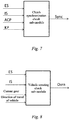
a target clutch torque-based creep control system for an automatic transmission of a heavy truck, wherein the control system comprises an internal combustion engine controlled by an engine control unit ECU having a speed closed-loop control function, and a clutch power cylinder, a transmission actuator, and a vehicle transmission system which are controlled by a transmission control unit TCU; the engine control unit ECU collects an accelerator pedal position signal AP, a brake switch signal BK, and a current engine speed ES, and the transmission control unit TCU collects a clutch position signal ACP, a transmission input shaft speed IS, a transmission output shaft speed OS, and a direction of travel of vehicle; the ECU and the TCU are connected to each other by means of a data communication bus, and the ECU sends the measured accelerator pedal position signal AP, the brake switch signal BK, and the current engine speed ES to the TCU by means of the data communication bus; a target torque calculation module and a change rate limitation module are added to the transmission control unit TCU; a clutch synchronization check sub-module, a vehicle coasting check sub-module, and a clutch overheating check sub-module are added to the transmission control unit TCU, and the TCU implements vehicle creep control according to an output signal of each sub-module; the vehicle creep control performed by the TCU comprises a creep control mode in a waiting state, a creep control mode in a hybrid accelerator state, a creep control mode in a positive engagement state, and a creep control mode in a synchronization state, and switching between the various different control modes is determined by means of a current vehicle state; the TCU obtains a target engine speed TS and a target clutch position ICP in different vehicle states by means of the vehicle creep control; the TCU sends the target engine speed TS to the ECU by means of the data communication bus, and the ECU controls a fuel injection quantity according to the received target engine speed TS and the current engine speed ES so as to implement engine speed closed-loop control; and the TCU adjusts, by means of the target clutch position ICP, the clutch-transmitted torque applied to an engine flywheel. - The clutch synchronization check sub-module checks a synchronization state Sync between the engine and the clutch in real time according to the current engine speed ES, the input shaft speed IS, the current clutch position signal ACP, and a clutch kiss point KP position; when the engine and the clutch are synchronized, the clutch synchronization check sub-module outputs a signal Sync = 1; and when the engine and the clutch are desynchronized, the clutch synchronization check sub-module outputs a signal Sync = 0.
the vehicle coasting check sub-module checks whether the vehicle is in a coasting state Ovrn in real time according to the current engine speed ES, the input shaft speed IS, a current gear, and the direction of travel of vehicle; when the vehicle is coasting, the vehicle coasting check sub-module outputs a signal Ovrn = 1; and when the vehicle is not coasting, the vehicle coasting check sub-module outputs a signal Ovrn = 0. - A clutch temperature estimation module used to estimate a current clutch temperature is disposed in the TCU, the clutch temperature estimation module is configured with an alarm temperature threshold and a protection temperature threshold, and the clutch overheating check sub-module determines a heat state OH of the clutch by comparing an estimated temperature obtained from the clutch temperature estimation module, the alarm temperature threshold, and the protection temperature threshold; when the estimated temperature exceeds the set alarm temperature threshold, the clutch switches from a normal state to an alarm state, and in this case, the clutch overheating check sub-module outputs a signal OH = 1; when the clutch is in the alarm state, if the estimated temperature continues to rise and exceeds the protection temperature threshold, the heat state of the clutch switches from the alarm state to a protection state, and in this case, the clutch overheating check sub-module outputs a signal OH = 2; when the clutch is in the protection state, if the estimated temperature drops, the heat state of the clutch does not switch to the alarm state until the estimated temperature drops below the alarm temperature threshold; and when the clutch is in the alarm state, if the estimated temperature drops and the estimated temperature drops below 60°C, the heat state of the clutch switches to the normal state, and in this case, the clutch overheating check sub-module outputs a signal OH = 0.
- An alarm module is further disposed in the TCU, wherein the alarm module is connected to the clutch overheating check sub-module, the alarm module comprises a buzzing alarm, and a buzzing frequency of the buzzing alarm is set to cooperate with the clutch temperature, that is, the buzzing frequency is higher when the clutch temperature is higher; and when the heat state of the clutch is in the alarm state, in the creep control mode in a hybrid accelerator state, the TCU can still implement creep control on the clutch, but the TCU sends a buzzing alarm to warn a driver that the clutch is about to overheat, and in a range from the alarm temperature threshold to the protection temperature threshold, the buzzing frequency is higher when the temperature is higher.
- When the vehicle enters into a creep mode, the vehicle creep control performed by the TCU enters into the creep control mode in a waiting state by default; and when the vehicle creep control performed by the TCU is in the creep control mode in a waiting state, if the vehicle coasting check sub-module outputs the signal Ovrn = 1, that is, the vehicle is in the coasting state, the vehicle creep control performed by the TCU preferentially switches from the creep control mode in a waiting state to the creep control mode in a positive engagement state.
- When the vehicle creep control performed by the TCU is in the creep control mode in a waiting state, if a driver presses down on the accelerator to a position that exceeds a trigger position of the accelerator, and the clutch overheating check sub-module outputs the signal OH = 0, that is, the heat state of the clutch is in the normal state, the vehicle creep control performed by the TCU switches from the creep control mode in a waiting state to the creep control mode in a hybrid accelerator state.
when the vehicle creep control performed by the TCU is in the creep control mode in a hybrid accelerator state, if the vehicle coasting check sub-module outputs the signal Ovrn = 1, that is, the vehicle is in the coasting state, the vehicle creep control performed by the TCU preferentially switches from the creep control mode in a hybrid accelerator state to the creep control mode in a positive engagement state.
when the vehicle creep control performed by the TCU is in the creep control mode in a hybrid accelerator state, if the clutch overheating check sub-module outputs the signal OH = 2, that is, the heat state of the clutch is in the protection state, the vehicle creep control performed by the TCU switches to a corresponding state according to the situation of a speed difference between the current engine speed ES and the input shaft speed IS, i.e. if ES - IS < 200 rpm, the vehicle creep control performed by the TCU switches from the creep control mode in a hybrid accelerator state to the creep control mode in a positive engagement state; and if ES - IS > 200 rpm, the vehicle creep control performed by the TCU switches from the creep control mode in a hybrid accelerator state to the creep control mode in a waiting state.
when the vehicle creep control performed by the TCU is in the creep control mode in a hybrid accelerator state, if the clutch synchronization check sub-module outputs the signal Sync = 1, that is, when the engine and the clutch are synchronized, the vehicle creep control performed by the TCU switches from the creep control mode in a hybrid accelerator state to the creep control mode in a synchronization state.
when the vehicle creep control performed by the TCU is in the creep control mode in a positive engagement state, if the clutch synchronization check sub-module outputs the signal Sync = 1, the vehicle creep control performed by the TCU switches from the creep control mode in a positive engagement state to the creep control mode in a synchronization state.
when the vehicle creep control performed by the TCU is in the creep control mode in a synchronization state, if the clutch synchronization check sub-module outputs the signal Sync = 0, that is, the engine and the clutch are desynchronized, or a driver presses down on a brake pedal, the vehicle creep control performed by the TCU switches from the creep control mode in a synchronization state to the creep control mode in a hybrid accelerator state.
when the vehicle creep control performed by the TCU is in the creep control mode in a waiting state, the target clutch position ICP is constantly set to the clutch kiss point position, that is, ICP = KP, and the target engine speed TS is constantly set to an idle speed, that is, TS = the idle speed of the engine.
when the vehicle creep control performed by the TCU is in the creep control mode in a positive engagement state, the target clutch position ICP positively engages at a fixed speed, that is, ICP[n] = ICP[n-1] - CP_stp, wherein ICP[n] is a target clutch position of a current calculation step, ICP[n-1] is a target clutch position of the last calculation step temporarily stored in the TCU, and CP stp is a calibrated clutch engagement position for each step length in the positive engagement state; and the target engine speed TS is maintained at a setting of the target engine speed prior to enabling of the positive engagement state. - When the vehicle creep control performed by the TCU is in the creep control mode in a synchronization state, the target clutch position ICP freezes at a clutch position ICP[SyncO] at which the synchronization state is enabled and remains unchanged, and the target engine speed TS is adjusted in the following method:
the TCU records a target engine speed value TS[SyncO] and an accelerator position AP[SyncO] at the enabling of the synchronization state, and calculates a target engine speed in the synchronization state by means of the following formula:
- When the vehicle creep control performed by the TCU is in the creep control mode in a hybrid accelerator state, the target engine speed TS and the target clutch position ICP are dynamically adjusted according to the following steps:
- step 1: the target torque calculation module calculates the driver target clutch torque ItdCltTrq according to the accelerator pedal position;
- step 2: an engine speed controller calculates a corresponding target engine speed TS according to the driver target clutch torque ItdCltTrq;
- step 3: the change rate limitation module calculates an allowable clutch torque change rate according to a difference between the target engine speed TS calculated in
step 2 and the current engine speed ES, that is, an allowable clutch torque change difference for one step length, and limits the currently calculated driver target clutch torque, wherein a target clutch torque obtained after the limitation is ItdCltTrqLmt; and - step 4: the TCU calculates the target clutch position ICP according to the limited target clutch torque ItdCltTrqLmt by means of performing interpolation on a clutch torque transmission curve.
- The beneficial effects achieved by the present invention by adopting the above-described technical solution are as follows:
- 1. In the target clutch torque-based creep control system for an automatic transmission of a heavy truck of the present invention, an increase in the engine speed is always slightly ahead of an increase in the clutch-transmitted torque, and both the engine speed and the torque are always coordinated with each other for control, so as to ensure that when a clutch load is small, the engine speed can be relatively low to reduce clutch slipping friction, and when the clutch load is large, the engine speed can be increased in advance to avoid the occurrence of insufficient engine power.
- 2. When the vehicle creep control performed by the TCU is in the creep control mode in a hybrid accelerator state, the control system of the present invention controls the clutch position according to a clutch torque transmission curve, wherein a difference in the change rate of the clutch-transmitted torque resulting from a position change is taken into consideration, so as to ensure that the driver can stably and linearly control the clutch torque and the vehicle speed.
-
-
Fig. 1 illustrates the basic structure of a whole vehicle power transmission chain comprising an automatic transmission which is applicable to the present invention. -
Fig. 2 illustrates the overall control structure of the present invention, comprising the relationships between all controllers and between a controller and a controlled object. -
Fig. 3 illustrates a logic model of a state machine for vehicle creep control performed by a TCU in the present invention. -
Fig. 4 illustrates a control flow chart of a target clutch position and a target engine speed when the vehicle creep control performed by the TCU is in a control mode in a hybrid accelerator state. -
Fig. 5 illustrates a curve for calculating a driver target clutch torque according to an accelerator pedal position in the present invention. -
Fig. 6 illustrates a curve for calculating the target clutch position according to a filtered driver target clutch torque in the present invention. -
Fig. 7 illustrates an input-output block diagram of a clutch synchronization check sub-module in the present invention. -
Fig. 8 illustrates an input-output block diagram of a vehicle coasting check sub-module in the present invention. -
Fig. 9 illustrates an input-output block diagram of a clutch overheating check sub-module in the present invention. -
Fig. 10 illustrates a logic diagram of enabling and disabling of a normal state, an alarm state, and a protection state of a clutch in the present invention. -
Fig. 11 illustrates a logic block diagram of dynamically limiting a clutch engagement speed according to a difference between the target engine speed and a current engine speed. -
Fig. 12 illustrates a curve for calculating the target engine speed according to the target clutch torque. -
Fig. 13 illustrates a change state curve diagram of the driver target clutch torque in a case where an accelerator position exceeds a trigger position TriggerAP, but does not reach a switch position SwitchAP. -
Fig. 14 illustrates a change state curve diagram of the driver target clutch torque in a case where the accelerator position exceeds the switch position SwitchAP, but does not reach 100% of the accelerator position. -
Fig. 15 illustrates a change state curve diagram of the target engine speed relative to the driver target clutch torque. -
Fig. 16 illustrates a change state curve diagram of the target engine speed TS, the current engine speed ES, a clutch-transmitted torque change amount Step, a limited target clutch torque, and the driver target clutch torque ItdCltTrq. -
Fig. 17 illustrates a change state curve diagram of the clutch torque and the engine speed in an operating condition of quickly pressing down on and quickly lifting off an accelerator. -
Fig. 18 illustrates a change state curve diagram of the clutch torque and the engine speed in an operating condition of stable accelerator creep implemented according to the control method of the present invention. - Wherein:
1.Internal combustion engine 2. Enginecontrol unit ECU 3.Speed sensor 5.Flywheel 6. Inputshaft speed sensor 7.Transmission actuator 8.Clutch power cylinder 9. Transmissioncontrol unit TCU 10.Clutch position sensor 11.Vehicle transmission system 12.Accelerator pedal sensor 13. Outputshaft speed sensor 14. Brake pedal switch - The present invention is further described below in detail with reference to the drawings and the specific embodiments, while the present invention is not limited to these embodiments.
- With regard to a target clutch torque-based creep control system for an automatic transmission of a heavy truck,
a vehicle automatic transmission system applicable to the control system should have the power assembly structure shown inFig. 1 . - That is, an engine control unit ECU2 having a speed closed-loop control function controls an
internal combustion engine 1, and a transmissioncontrol unit TCU 9 controls aclutch power cylinder 8, atransmission actuator 7, and anothervehicle transmission system 11 comprising a transmission shaft. The TCU controls a position of a dry type friction clutch by means of theclutch power cylinder 8, so as to control the torque transmitted by the engine to thetransmission actuator 7. - In the control system, an
accelerator pedal sensor 12 is added at an accelerator pedal position to measure an accelerator pedal position signal AP, aspeed sensor 3 is added to anengine flywheel 5 to measure a current engine speed ES, abrake pedal switch 14 is added to a brake pedal to measure a brake switch signal BK, aclutch position sensor 10 is added at a clutch position to measure a current clutch position signal ACP, an inputshaft speed sensor 6 is added to a transmission input shaft to measure an input shaft speed IS, and an outputshaft speed sensor 13 is added to a transmission output shaft to measure an output shaft speed OS and a direction of travel of vehicle. The ECU and the TCU are connected to each other by means of a data communication bus, and the ECU sends the measured accelerator pedal position signal AP, the brake switch signal BK, and the current engine speed ES to the TCU by means of the data communication bus. The TCU sends a target engine speed TS to the ECU by means of the data communication bus. The data communication bus can be any network protocol bus that satisfies a standard definition, for example, J1922, J1939, ISO11898, or the like. - As shown in
Fig. 2 , the TCU sends the target engine speed TS to the ECU by means of the data communication bus, and the ECU controls a fuel injection quantity according to the received target engine speed TS and the current engine speed ES so as to implement engine speed closed-loop control. The TCU adjusts, by means of the target clutch position ICP, the clutch-transmitted torque applied to an engine flywheel. - The target engine speed TS and the target clutch position ICP are obtained by means of the following vehicle creep control being performed by the TCU.
- In the control system, a target torque calculation module and a change rate limitation module are added to the TCU. In the control system, a clutch synchronization check sub-module used to detect a vehicle state in real time, a vehicle coasting check sub-module, and a clutch overheating check sub-module are added to the TCU. The TCU achieves the vehicle creep control according to an output signal of each sub-module. The vehicle creep control performed by the TCU comprises a creep control mode in a waiting state, a creep control mode in a hybrid accelerator state, a creep control mode in a positive engagement state, and a creep control mode in a synchronization state; and switching between the various different control modes is determined by a current vehicle state. The TCU obtains a target engine speed TS and a target clutch position ICP in different vehicle states by means of the vehicle creep control.
- As shown in
Fig. 7 , the clutch synchronization check sub-module checks a synchronization state Sync between the engine and the clutch in real time according to the current engine speed ES, the input shaft speed IS, the current clutch position signal ACP, and a clutch kiss point KP position. when the engine and the clutch are synchronized, the clutch synchronization check sub-module outputs a signal Sync = 1; and when the engine and the clutch are desynchronized, the clutch synchronization check sub-module outputs a signal Sync = 0. - As shown in
Fig. 8 , the vehicle coasting check sub-module checks whether the vehicle is in a coasting state Ovrn in real time according to the current engine speed ES, the input shaft speed IS, a current gear, and the direction of travel of vehicle. when the vehicle is coasting, the vehicle coasting check sub-module outputs a signal Ovrn = 1; and when the vehicle is not coasting, the vehicle coasting check sub-module outputs a signal Ovrn = 0. - As shown in
Fig. 9 and Fig. 10 , a clutch temperature estimation module used to estimate a current clutch temperature is disposed in the TCU, wherein the clutch temperature estimation module is configured with an alarm temperature threshold and a protection temperature threshold, and the clutch overheating check sub-module determines a heat state OH of the clutch by comparing an estimated temperature obtained from the clutch temperature estimation module, the alarm temperature threshold, and the protection temperature threshold. when the estimated temperature exceeds the set alarm temperature threshold, the clutch switches from a normal state to an alarm state, and in this case, the clutch overheating check sub-module outputs a signal OH = 1; when the clutch is in the alarm state, if the estimated temperature continues to rise and exceeds the protection temperature threshold, the heat state of the clutch switches from the alarm state to a protection state, and in this case, the clutch overheating check sub-module outputs a signal OH = 2; When the clutch is in the protection state, if the estimated temperature drops, the heat state of the clutch does not switch to the alarm state until the estimated temperature drops below the alarm temperature threshold. when the clutch is in the alarm state, if the estimated temperature drops and the estimated temperature drops below 60°C, the heat state of the clutch switches to the normal state, and in this case, the clutch overheating check sub-module outputs a signal OH = 0. - An alarm module is further disposed in the TCU, wherein the alarm module is connected to the clutch overheating check sub-module, the alarm module comprises a buzzing alarm, and a buzzing frequency of the buzzing alarm is set to cooperate with the clutch temperature, that is, the buzzing frequency is higher when the clutch temperature is higher. When the heat state of the clutch is in the alarm state, in the creep control mode in a hybrid accelerator state, the TCU can still implement creep control on the clutch, but the TCU sends a buzzing alarm to warn a driver that the clutch is about to overheat, and in a range from the alarm temperature threshold to the protection temperature threshold, the buzzing frequency is higher when the temperature is higher.
- The vehicle creep control performed by the TCU enters into different states according to the current vehicle state, and in the different states, the TCU controls the target engine speed TS and the target clutch position ICP in different modes.
- As shown in
Fig. 3 , in a mode of the vehicle creep control being performed by the TCU, the switching logic between all of the states is as follows. - When the vehicle enters into a creep mode, the vehicle creep control performed by the TCU enters into the creep control mode in a waiting state by default. when the vehicle creep control performed by the TCU is in the creep control mode in a waiting state, if the vehicle coasting check sub-module outputs the signal Ovrn = 1, that is, the vehicle is in the coasting state, the vehicle creep control performed by the TCU preferentially switches from the creep control mode in a waiting state to the creep control mode in a positive engagement state.
- When the vehicle creep control performed by the TCU is in the creep control mode in a waiting state, if a driver presses down on the accelerator to a position that exceeds a trigger accelerator position TriggerAP, and the clutch overheating check sub-module outputs the signal OH = 0, that is, the heat state of the clutch is in the normal state, the vehicle creep control performed by the TCU switches from the creep control mode in a waiting state to the creep control mode in a hybrid accelerator state.
when the vehicle creep control performed by the TCU is in the creep control mode in a hybrid accelerator state, if the vehicle coasting check sub-module outputs the signal Ovrn = 1, that is, the vehicle is in the coasting state, the vehicle creep control performed by the TCU preferentially switches from the creep control mode in a hybrid accelerator state to the creep control mode in a positive engagement state.
when the vehicle creep control performed by the TCU is in the creep control mode in a hybrid accelerator state, if the clutch overheating check sub-module outputs the signal OH = 2, that is, the heat state of the clutch is in the protection state, the vehicle creep control performed by the TCU switches to a corresponding state according to the situation of a speed difference between the current engine speed ES and the input shaft speed IS, i.e. if ES - IS < 200 rpm, the vehicle creep control performed by the TCU switches from the creep control mode in a hybrid accelerator state to the creep control mode in a positive engagement state; and if ES - IS > 200 rpm, the vehicle creep control performed by the TCU switches from the creep control mode in a hybrid accelerator state to the creep control mode in a waiting state.
when the vehicle creep control performed by the TCU is in the creep control mode in a hybrid accelerator state, if the clutch synchronization check sub-module outputs the signal Sync = 1, that is, when the engine and the clutch are synchronized, the vehicle creep control performed by the TCU switches from the creep control mode in a hybrid accelerator state to the creep control mode in a synchronization state.
when the vehicle creep control performed by the TCU is in the creep control mode in a positive engagement state, if the clutch synchronization check sub-module outputs the signal Sync = 1, the vehicle creep control performed by the TCU switches from the creep control mode in a positive engagement state to the creep control mode in a synchronization state. - When the vehicle creep control performed by the TCU is in the creep control mode in a synchronization state, if the clutch synchronization check sub-module outputs the signal Sync = 0, that is, the engine and the clutch are desynchronized, or a driver presses down on a brake pedal, that is, BK = 1, the vehicle creep control performed by the TCU switches from the creep control mode in a synchronization state to the creep control mode in a hybrid accelerator state.
- In these different states, a control system of the target clutch position ICP and the target engine speed TS is as follows.
when the vehicle creep control performed by the TCU is in the creep control mode in a waiting state, the target clutch position ICP is constantly set to the clutch kiss point position, that is, ICP = KP, and the target engine speed TS is constantly set to an idle speed, that is, TS = the idle speed of the engine.
when the vehicle creep control performed by the TCU is in the creep control mode in a positive engagement state, the target clutch position ICP positively engages at a fixed speed, that is, ICP[n] = ICP[n-1] - CP_stp, wherein ICP[n] is a target clutch position of a current calculation step, ICP[n-1] is a target clutch position of the last calculation step temporarily stored in the TCU, and CP stp is a calibrated clutch engagement position for each step length in the positive engagement state; and The target engine speed TS is maintained at a setting of the target engine speed prior to enabling of the positive engagement state. - When the vehicle creep control performed by the TCU is in the creep control mode in a synchronization state, the target clutch position ICP freezes at a clutch position ICP[SyncO] at which the synchronization state is enabled and remains unchanged, and the target engine speed TS is adjusted in the following method:
the TCU records a target engine speed value TS[SyncO] and an accelerator position AP[SyncO] at the enabling of the synchronization state, and calculates a target engine speed in the synchronization state by means of the following formula:
- As shown in
Fig. 4 , when the vehicle creep control performed by the TCU is in the creep control mode in a hybrid accelerator state, the target engine speed TS and the target clutch position ICP are dynamically adjusted according to the following steps: - Step 1: the target torque calculation module calculates the driver target clutch torque ItdCltTrq according to the accelerator pedal position by means of the curve shown in
Fig. 5. Fig. 5 illustrates the curve for calculating the driver target clutch torque according to the accelerator pedal position. The curve is determined by means of experimental calibration, so as to implement different system sensitivity responses in different accelerator opening degrees. When the driver presses down on the accelerator to a position that exceeds the trigger position TriggerAP (5% of accelerator stroke), the driver target clutch torque slowly increases along with the increase in the accelerator stroke. As shown inFig. 13 , when the accelerator position exceeds the trigger position TriggerAP, but does not reach a switch position SwitchAP (65% of the accelerator stroke), the driver target clutch torque ItdCltTrq is calculated by means of the curve shown inFig. 5 , and the driver target clutch torque ItdCltTrq proportionally changes within a range of 0%-35% of a rated engine torque. When the accelerator position reaches the switch position SwitchAP, the driver target clutch torque rapidly increases along with the increase in the accelerator stroke. As shown inFig. 14 , when the accelerator position exceeds the switch position SwitchAP (65% of the accelerator stroke), but does not reach 100% of the accelerator position, the driver target clutch torque ItdCltTrq is calculated by means of the curve shown inFig. 5 , and the driver target clutch torque ItdCltTrq proportionally changes within a range of 35%-50% of the rated engine torque. When the accelerator position reaches 100% of the accelerator position, the driver target clutch torque reaches the available torque corresponding to an optimal transient engine speed. The optimal transient engine speed and the available torque corresponding thereto are obtained by means of experimental calibration of the engine. For a heavy pressurized diesel engine, under the effects of both an external characteristic limitation and a smoke intensity limitation, the maximum transient torque reachable for the engine varies according to different speeds. The maximum transient available torque is limited by an external characteristic when the speed is relatively low. The maximum transient available torque is limited by smoke intensity control when the speed is relatively high. The transient available torque reaches a maximum value under the optimal transient speed. Therefore, in a creep operating condition in which the engine needs to respond quickly, a maximum value of the target clutch torque curve is set to the available torque corresponding to the optimal transient speed. - Step 2: an engine speed controller calculates a corresponding target engine speed TS according to the driver target clutch torque ItdCltTrq by means of the pre-calibrated curve shown in
Fig. 12. Fig. 12 illustrates the curve for calculating the target engine speed according to the target clutch torque, wherein the curve is obtained by means of experimental calibration according to an engine speed controller performance. In the curve, the required torque output by the engine speed controller basically corresponds to a speed difference required by a proportional control link. As shown inFig. 12 andFig. 15 , when the target clutch torque is less than a starting torque StartTrq, the target engine speed is kept at an idle speed. The target engine speed gradually increases along with the increase in the target clutch torque, and the target engine speed reaches a saturated speed SaturateSpd when the target clutch torque reaches a saturated torque SaturateTrq. Specifically, the target engine speed TS increases by 100 rpm each time that the driver target clutch torque increases by 10%. The starting torque StartTrq, the saturated torque SaturateTrq, and the saturated speed SaturateSpd are all determined by means of calibration according to the engine speed controller performance. - Step 3: the change rate limitation module calculates an allowable clutch torque change rate according to a difference between the target engine speed TS calculated in
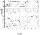
step 2 and the current engine speed ES, that is, an allowable clutch torque change difference for one step length, and limits the currently calculated driver target clutch torque, and as shown inFig. 11 , the target clutch torque obtained after the limitation is ItdCltTrqLmt. InFig. 11 , TS[n] is a target engine speed of a current calculation step, ES[n] is the actual engine speed of the current calculation step, ItdCltTrq[n] is a target clutch torque of the current calculation step, ItdCltTrqLmt[n-1] is a limited target clutch torque of the last calculation step, ItdCltTrqLmt[n] is a limited target clutch torque of the current calculation step obtained by a final calculation, Step[n] is an allowable clutch-transmitted torque change amount of the current calculation step, Min represents the searching of a minimum value between two input signals, and 1/Z represents temporarily storing a calculation result of the last step.Fig. 16 illustrates a change state curve diagram of the target engine speed TS, the current engine speed ES, a clutch-transmitted torque change amount Step, a limited target clutch torque, and the driver target clutch torque ItdCltTrq. It can be seen fromFig. 16 that the change rate limitation module calculates the allowable clutch-transmitted torque change amount Step at a corresponding calculation point according to the difference between TS and ES, and a change amount of the limited target clutch torque in each calculation step cannot exceed the allowable torque change amount Step at the corresponding calculation point. - Step 4: the transmission control unit TCU calculates the target clutch position ICP according to the limited target clutch torque ItdCltTrqLmt by means of performing interpolation on a clutch torque transmission curve shown in
Fig. 6 . The TCU directly controls the inlet pressure of the clutch power cylinder to implement control on the target clutch position.Fig. 6 illustrates a curve for calculating the target clutch position according to a filtered driver target clutch torque. The curve reflects a change in the maximum torque that can be transmitted by the clutch in different strokes, and the curve is obtained by means of automatic transmission AMT software algorithm self-identification in a normal starting and traveling process of the vehicle. The clutch does not transmit torque before the clutch position reaches the clutch kiss point KP. From the clutch kiss point KP position, the maximum torque that can be transmitted by the clutch gradually increases, and when the clutch engages more deeply, a change rate of the maximum torque that can be transmitted by the clutch becomes larger along with the change in the position. -
Fig. 17 illustrates a change state curve diagram of the clutch torque and the engine speed in an operating condition of quickly pressing down on and quickly lifting off an accelerator.Fig. 18 illustrates a change state curve diagram of the clutch torque and the engine speed in an operating condition of stable accelerator creep implemented according to the control method of the present invention. It can be found by comparingFig. 17 and Fig. 18 that, controlling the clutch position according to the clutch torque transmission curve of the present invention can ensure that the driver can stably and linearly control the clutch torque and the vehicle speed. - The portion of the present invention which is not described herein can be implemented by adopting or referring to the prior art.
- The specific embodiments described in the text are merely descriptive examples of the spirit of the present invention. One skilled in the art would be able to make various modifications or supplements to the described specific embodiments or substitutions in similar manners, without deviating from the spirit of the present invention or exceeding the scope defined by the attached claims.
Claims (16)
- A target clutch torque-based creep control system for an automatic transmission of a heavy truck, characterized in that:the control system comprises an internal combustion engine controlled by an engine control unit ECU having a speed closed-loop control function, and a clutch power cylinder, a transmission actuator, and a vehicle transmission system which are controlled by a transmission control unit TCU; whereinthe engine control unit ECU collects an accelerator pedal position signal AP, a brake switch signal BK, and a current engine speed ES, and the transmission control unit TCU collects a clutch position signal ACP, a transmission input shaft speed IS, a transmission output shaft speed OS, and a direction of travel of vehicle; the ECU and the TCU are connected to each other by means of a data communication bus, and the ECU sends the measured accelerator pedal position signal AP, the brake switch signal BK, and the current engine speed ES to the TCU by means of the data communication bus;a target torque calculation module and a change rate limitation module are added to the transmission control unit TCU;a clutch synchronization check sub-module, a vehicle coasting check sub-module, and a clutch overheating check sub-module are added to the transmission control unit TCU, and the TCU implements vehicle creep control according to an output signal of each sub-module; the vehicle creep control performed by the TCU comprises a creep control mode in a waiting state, a creep control mode in a hybrid accelerator state, a creep control mode in a positive engagement state, and a creep control mode in a synchronization state, and switching between the various different control modes is determined by means of a current vehicle state; the TCU obtains a target engine speed TS and a target clutch position ICP in different vehicle states by means of the vehicle creep control;the TCU sends the target engine speed TS to the ECU by means of the data communication bus, and the ECU controls a fuel injection quantity according to the received target engine speed TS and the current engine speed ES so as to implement engine speed closed-loop control; and the TCU adjusts, by means of the target clutch position ICP, a clutch-transmitted torque applied to an engine flywheel.
- The target clutch torque-based creep control system for an automatic transmission of a heavy truck as claimed in claim 1, characterized in that:the clutch synchronization check sub-module checks a synchronization state Sync between the engine and the clutch in real time according to the current engine speed ES, the input shaft speed IS, the current clutch position signal ACP, and a clutch kiss point KP position;when the engine and the clutch are synchronized, the clutch synchronization check sub-module outputs a signal Sync = 1; and when the engine and the clutch are desynchronized, the clutch synchronization check sub-module outputs a signal Sync = 0.
- The target clutch torque-based creep control system for an automatic transmission of a heavy truck as claimed in claim 2, characterized in that:the vehicle coasting check sub-module checks whether the vehicle is in a coasting state Ovrn in real time according to the current engine speed ES, the input shaft speed IS, a current gear, and the direction of travel of vehicle;when the vehicle is coasting, the vehicle coasting check sub-module outputs a signal Ovrn = 1; and when the vehicle is not coasting, the vehicle coasting check sub-module outputs a signal Ovrn = 0.
- The target clutch torque-based creep control system for an automatic transmission of a heavy truck as claimed in claim 3, characterized in that:a clutch temperature estimation module used to estimate a current clutch temperature is disposed in the TCU, the clutch temperature estimation module is configured with an alarm temperature threshold and a protection temperature threshold, and the clutch overheating check sub-module determines a heat state OH of the clutch by comparing an estimated temperature obtained from the clutch temperature estimation module, the alarm temperature threshold, and the protection temperature threshold;when the estimated temperature exceeds the set alarm temperature threshold, the clutch switches from a normal state to an alarm state, and in this case, the clutch overheating check sub-module outputs a signal OH = 1;when the clutch is in the alarm state, if the estimated temperature continues to rise and exceeds the protection temperature threshold, the heat state of the clutch switches from the alarm state to a protection state, and in this case, the clutch overheating check sub-module outputs a signal OH = 2;when the clutch is in the protection state, if the estimated temperature drops, the heat state of the clutch does not switch to the alarm state until the estimated temperature drops below the alarm temperature threshold; andwhen the clutch is in the alarm state, if the estimated temperature drops and the estimated temperature drops below 60°C, the heat state of the clutch switches to the normal state, and in this case, the clutch overheating check sub-module outputs a signal OH = 0.
- The target clutch torque-based creep control system for an automatic transmission of a heavy truck as claimed in claim 4, characterized in that:an alarm module is further disposed in the TCU, the alarm module is connected to the clutch overheating check sub-module, the alarm module comprises a buzzing alarm, and a buzzing frequency of the buzzing alarm is set to cooperate with the clutch temperature, that is, the buzzing frequency is higher when the clutch temperature is higher; andwhen the heat state of the clutch is in the alarm state, in the creep control mode in a hybrid accelerator state, the TCU can still implement creep control on the clutch, but the TCU sends a buzzing alarm to warn a driver that the clutch is about to overheat, and in a range from the alarm temperature threshold to the protection temperature threshold, the buzzing frequency is higher when the temperature is higher.
- The target clutch torque-based creep control system for an automatic transmission of a heavy truck as claimed in claim 3, characterized in that:when the vehicle enters into a creep mode, the vehicle creep control performed by the TCU enters into the creep control mode in a waiting state by default; andwhen the vehicle creep control performed by the TCU is in the creep control mode in a waiting state, if the vehicle coasting check sub-module outputs the signal Ovrn = 1, that is, the vehicle is in the coasting state, the vehicle creep control performed by the TCU preferentially switches from the creep control mode in a waiting state to the creep control mode in a positive engagement state.
- The target clutch torque-based creep control system for an automatic transmission of a heavy truck as claimed in claim 4, characterized in that:
when the vehicle creep control performed by the TCU is in the creep control mode in a waiting state, if a driver presses down on the accelerator to a position that exceeds a set accelerator position, and the clutch overheating check sub-module outputs the signal OH = 0, that is, the heat state of the clutch is in the normal state, the vehicle creep control performed by the TCU switches from the creep control mode in a waiting state to the creep control mode in a hybrid accelerator state. - The target clutch torque-based creep control system for an automatic transmission of a heavy truck as claimed in claim 3, characterized in that:
when the vehicle creep control performed by the TCU is in the creep control mode in a hybrid accelerator state, if the vehicle coasting check sub-module outputs the signal Ovrn = 1, that is, the vehicle is in the coasting state, the vehicle creep control performed by the TCU preferentially switches from the creep control mode in a hybrid accelerator state to the creep control mode in a positive engagement state. - The target clutch torque-based creep control system for an automatic transmission of a heavy truck as claimed in claim 4, characterized in that:
when the vehicle creep control performed by the TCU is in the creep control mode in a hybrid accelerator state, if the clutch overheating check sub-module outputs the signal OH = 2, that is, the heat state of the clutch is in the protection state, the vehicle creep control performed by the TCU switches to a corresponding state according to the situation of a speed difference between the current engine speed ES and the input shaft speed IS, i.e. if ES - IS < 200 rpm, the vehicle creep control performed by the TCU switches from the creep control mode in a hybrid accelerator state to the creep control mode in a positive engagement state; and if ES - IS > 200 rpm, the vehicle creep control performed by the TCU switches from the creep control mode in a hybrid accelerator state to the creep control mode in a waiting state. - The target clutch torque-based creep control system for an automatic transmission of a heavy truck as claimed in claim 2, characterized in that:
when the vehicle creep control performed by the TCU is in the creep control mode in a hybrid accelerator state, if the clutch synchronization check sub-module outputs the signal Sync = 1, that is, when the engine and the clutch are synchronized, the vehicle creep control performed by the TCU switches from the creep control mode in a hybrid accelerator state to the creep control mode in a synchronization state. - The target clutch torque-based creep control system for an automatic transmission of a heavy truck as claimed in claim 2, characterized in that:
when the vehicle creep control performed by the TCU is in the creep control mode in a positive engagement state, if the clutch synchronization check sub-module outputs the signal Sync = 1, the vehicle creep control performed by the TCU switches from the creep control mode in a positive engagement state to the creep control mode in a synchronization state. - The target clutch torque-based creep control system for an automatic transmission of a heavy truck as claimed in claim 2, characterized in that:
when the vehicle creep control performed by the TCU is in the creep control mode in a synchronization state, if the clutch synchronization check sub-module outputs the signal Sync = 0, that is, the engine and the clutch are desynchronized, or a driver presses down on a brake pedal, the vehicle creep control performed by the TCU switches from the creep control mode in a synchronization state to the creep control mode in a hybrid accelerator state. - The target clutch torque-based creep control system for an automatic transmission of a heavy truck as claimed in any one of claims 1-12, characterized in that:
when the vehicle creep control performed by the TCU is in the creep control mode in a waiting state, the target clutch position ICP is constantly set to the clutch kiss point position, that is, ICP = KP, and the target engine speed TS is constantly set to an idle speed, that is, TS = the idle speed of the engine. - The target clutch torque-based creep control system for an automatic transmission of a heavy truck as claimed in any one of claims 1-12, characterized in that:
when the vehicle creep control performed by the TCU is in the creep control mode in a positive engagement state, the target clutch position ICP positively engages at a fixed speed, that is, ICP[n] = ICP[n-1] - CP_stp, wherein ICP[n] is a target clutch position of a current calculation step, ICP[n-1] is a target clutch position of the last calculation step temporarily stored in the TCU, and CP stp is a calibrated clutch engagement position for each step length in the positive engagement state; and the target engine speed TS is maintained at the setting of the target engine speed prior to enabling of the positive engagement state. - The target clutch torque-based creep control system for an automatic transmission of a heavy truck as claimed in any one of claims 2-12, characterized in that:
when the vehicle creep control performed by the TCU is in the creep control mode in a synchronization state, the target clutch position ICP freezes at a clutch position ICP[SyncO] at which the synchronization state is enabled and remains unchanged, and the target engine speed TS is adjusted in the following method:
the TCU records a target engine speed value TS[SyncO] and an accelerator position AP[SyncO] at the enabling of the synchronization state, and calculates a target engine speed in the synchronization state by means of the following formula:
- The target clutch torque-based creep control system for an automatic transmission of a heavy truck as claimed in any one of claims 1-12, characterized in that:
when the vehicle creep control performed by the TCU is in the creep control mode in a hybrid accelerator state, the target engine speed TS and the target clutch position ICP are dynamically adjusted according to the following steps:step 1: the target torque calculation module calculates the driver target clutch torque ItdCltTrq according to the accelerator pedal position;step 2: an engine speed controller calculates a corresponding target engine speed TS according to the driver target clutch torque ItdCltTrq;step 3: the change rate limitation module calculates an allowable clutch torque change rate according to a difference between the target engine speed TS calculated in step 2 and the current engine speed ES, that is, an allowable clutch torque change difference for one step length, and limits the currently calculated driver target clutch torque, wherein a target clutch torque obtained after the limitation is ItdCltTrqLmt; andstep 4: the TCU calculates the target clutch position ICP according to the limited target clutch torque ItdCltTrqLmt by means of performing interpolation on a clutch torque transmission curve.
Applications Claiming Priority (2)
| Application Number | Priority Date | Filing Date | Title |
|---|---|---|---|
| CN201611011110.3A CN106696964B (en) | 2016-11-17 | 2016-11-17 | Heavy truck automatic gear-box crawling control system based on clutch target torque |
| PCT/CN2017/111401 WO2018090957A1 (en) | 2016-11-17 | 2017-11-16 | Target clutch torque-based creep control system for automatic transmission of heavy truck |
Publications (3)
| Publication Number | Publication Date |
|---|---|
| EP3543080A1 true EP3543080A1 (en) | 2019-09-25 |
| EP3543080A4 EP3543080A4 (en) | 2020-07-15 |
| EP3543080B1 EP3543080B1 (en) | 2022-04-13 |
Family
ID=58940483
Family Applications (1)
| Application Number | Title | Priority Date | Filing Date |
|---|---|---|---|
| EP17872404.3A Active EP3543080B1 (en) | 2016-11-17 | 2017-11-16 | Target clutch torque-based creep control system for automatic transmission of heavy truck |
Country Status (3)
| Country | Link |
|---|---|
| EP (1) | EP3543080B1 (en) |
| CN (1) | CN106696964B (en) |
| WO (1) | WO2018090957A1 (en) |
Cited By (2)
| Publication number | Priority date | Publication date | Assignee | Title |
|---|---|---|---|---|
| WO2021140284A1 (en) * | 2020-01-09 | 2021-07-15 | Psa Automobiles Sa | Method for optimizing the engine speed of a heat engine of a vehicle with an automatic gearbox during coupling |
| FR3151274A1 (en) * | 2023-07-19 | 2025-01-24 | Psa Automobiles Sa | METHOD FOR DEACTIVATING A CREEP MODE OF A VEHICLE BASED ON A CLUTCH TEMPERATURE |
Families Citing this family (13)
| Publication number | Priority date | Publication date | Assignee | Title |
|---|---|---|---|---|
| CN106696964B (en) * | 2016-11-17 | 2018-12-04 | 威伯科汽车控制系统(中国)有限公司 | Heavy truck automatic gear-box crawling control system based on clutch target torque |
| CN108583367B (en) * | 2018-04-04 | 2020-03-13 | 威马智慧出行科技(上海)有限公司 | Motor creep working condition switching coordination control method and system for electric automobile |
| CN109263642B (en) * | 2018-09-12 | 2020-06-23 | 安徽江淮汽车集团股份有限公司 | Vehicle creep protection method |
| CN110174911A (en) * | 2019-04-12 | 2019-08-27 | 汉腾汽车有限公司 | A kind of scaling method of front axle automatic gear-box control unit |
| CN110926389A (en) * | 2019-12-05 | 2020-03-27 | 武汉理工大学 | A kind of heavy commercial vehicle AMT clutch slip point position measurement system and method |
| CN113022550A (en) * | 2019-12-24 | 2021-06-25 | 北京宝沃汽车股份有限公司 | Clutch control method and device for hybrid vehicle, storage medium and vehicle |
| CN111638645B (en) * | 2020-05-28 | 2022-04-19 | 西安法士特汽车传动有限公司 | Closed-loop control system and method for rear PTO of high-power tractor |
| CN113404855B (en) * | 2021-06-16 | 2023-04-21 | 徐工集团工程机械股份有限公司道路机械分公司 | Direct gear shifting system and method with peristaltic walking function |
| CN114291091B (en) * | 2022-01-24 | 2023-07-25 | 一汽解放汽车有限公司 | A control method for a creeping mode of a vehicle |
| CN114992258B (en) * | 2022-05-31 | 2024-03-26 | 中国第一汽车股份有限公司 | Method, device, equipment and storage medium for calibrating position of clutch half-combining point |
| CN115451122B (en) * | 2022-09-22 | 2023-11-07 | 陕西法士特齿轮有限责任公司 | AMT clutch high-temperature early warning protection device, protection method and automobile |
| CN116838728B (en) * | 2023-06-30 | 2025-12-19 | 潍柴动力股份有限公司 | Clutch position adjusting method and device and hybrid vehicle |
| CN119244389B (en) * | 2024-09-30 | 2025-09-09 | 东风商用车有限公司 | Engine torque-reducing function control method, device, equipment and readable storage medium |
Family Cites Families (13)
| Publication number | Priority date | Publication date | Assignee | Title |
|---|---|---|---|---|
| GB9504681D0 (en) * | 1995-03-08 | 1995-04-26 | Eaton Corp | Improvements in vehicle control |
| JP4034089B2 (en) * | 2002-03-07 | 2008-01-16 | 株式会社日立製作所 | Creep control device and method for automatic transmission |
| JP2007024094A (en) * | 2005-07-13 | 2007-02-01 | Mitsubishi Fuso Truck & Bus Corp | Clutch control device |
| CN102050119B (en) * | 2009-10-29 | 2013-07-17 | 上海通用汽车有限公司 | Method for achieving automatic transmission (AT) low-speed mode on vehicle equipped with automated manual transmission |
| US8775044B2 (en) * | 2011-06-08 | 2014-07-08 | Ford Global Technologies, Llc | Clutch torque trajectory correction to provide torque hole filling during a ratio upshift |
| DE112012002717B4 (en) * | 2011-06-30 | 2021-10-14 | Schaeffler Technologies AG & Co. KG | Method and device for avoiding or reducing chatter vibrations |
| US8825319B2 (en) * | 2012-05-21 | 2014-09-02 | GM Global Technology Operations LLC | Automatic transmission input clutch control |
| CN103029708B (en) * | 2013-01-07 | 2015-08-19 | 上海汽车变速器有限公司 | Based on control method and the system thereof of driving engine start and stop |
| CN103359104B (en) * | 2013-07-23 | 2015-12-02 | 安徽江淮汽车股份有限公司 | Automobile wriggling control method and system |
| CN103557319B (en) * | 2013-10-31 | 2016-02-24 | 长城汽车股份有限公司 | A kind of automatic gear automobile low speed crawling controlling method |
| CN104925049B (en) * | 2015-07-06 | 2017-07-04 | 安徽江淮汽车集团股份有限公司 | The wriggling interaction control method and system of a kind of double-clutch automatic gearbox automobile |
| CN105673832B (en) * | 2016-01-15 | 2017-10-31 | 上海汽车变速器有限公司 | Double-clutch automatic gearbox half hitch chalaza operating condition control method |
| CN106696964B (en) * | 2016-11-17 | 2018-12-04 | 威伯科汽车控制系统(中国)有限公司 | Heavy truck automatic gear-box crawling control system based on clutch target torque |
-
2016
- 2016-11-17 CN CN201611011110.3A patent/CN106696964B/en active Active
-
2017
- 2017-11-16 WO PCT/CN2017/111401 patent/WO2018090957A1/en not_active Ceased
- 2017-11-16 EP EP17872404.3A patent/EP3543080B1/en active Active
Cited By (3)
| Publication number | Priority date | Publication date | Assignee | Title |
|---|---|---|---|---|
| WO2021140284A1 (en) * | 2020-01-09 | 2021-07-15 | Psa Automobiles Sa | Method for optimizing the engine speed of a heat engine of a vehicle with an automatic gearbox during coupling |
| FR3106107A1 (en) * | 2020-01-09 | 2021-07-16 | Psa Automobiles Sa | PROCESS FOR OPTIMIZING A THERMAL ENGINE SPEED OF A VEHICLE WITH AN AUTOMOTIZED GEARBOX, IN PARTICULAR DURING BORING. |
| FR3151274A1 (en) * | 2023-07-19 | 2025-01-24 | Psa Automobiles Sa | METHOD FOR DEACTIVATING A CREEP MODE OF A VEHICLE BASED ON A CLUTCH TEMPERATURE |
Also Published As
| Publication number | Publication date |
|---|---|
| WO2018090957A1 (en) | 2018-05-24 |
| CN106696964A (en) | 2017-05-24 |
| EP3543080A4 (en) | 2020-07-15 |
| CN106696964B (en) | 2018-12-04 |
| EP3543080B1 (en) | 2022-04-13 |
Similar Documents
| Publication | Publication Date | Title |
|---|---|---|
| EP3543080A1 (en) | Target clutch torque-based creep control system for automatic transmission of heavy truck | |
| EP3543079B1 (en) | Target clutch position control method based on clutch torque transmission curve | |
| EP3044063B1 (en) | Vehicle controller and method | |
| US9150218B2 (en) | Hybrid vehicle | |
| US20130311055A1 (en) | Automatic transmission input clutch control | |
| EP2969686B1 (en) | System and method for detecting vehicle clutch touch point | |
| US20180015926A1 (en) | Powertrain lash management | |
| US10988140B2 (en) | Optimization of concurrent operation of predictive cruise control and idle coast management control | |
| KR101416375B1 (en) | Method and system for setting learn period of engine clutch of hybrid electric vehicle | |
| CN103561988A (en) | Vehicle and method and system for controlling a vehicle | |
| US10710586B2 (en) | Systems and methods for idle coasting management | |
| CN101676541A (en) | Cold-start emission reduction strategy for coordinated torque control systems | |
| CN109322990B (en) | Sliding working condition torque control method | |
| CN104989537A (en) | Anti-flameout control method for hybrid power engine | |
| US10393195B2 (en) | Optimization of concurrent operation of predictive cruise control and idle coast management control | |
| US11352006B2 (en) | Travel control device, vehicle, and travel control method | |
| JP2018523056A (en) | Method and apparatus for controlling restart of an internal combustion engine of a vehicle at the end of a sailing operation | |
| WO2014065062A1 (en) | Vehicular drive apparatus | |
| CN103075507A (en) | Control method for neutral gear switching of automatic transmission during vehicle running | |
| US11400912B2 (en) | Coasting management control of a vehicle with a road speed governor | |
| CN105143644B (en) | Combustion engine control | |
| US20090070018A1 (en) | Method and device for controlling a drive unit | |
| KR20020086708A (en) | Method and device for controlling the drive unit of a motor vehicle | |
| KR100836915B1 (en) | Controlling method for damper clutch of automatic transmission and system thereof | |
| KR101154399B1 (en) | Preventing method for brake slipping in tcu limphome with hybrid motor assist |
Legal Events
| Date | Code | Title | Description |
|---|---|---|---|
| STAA | Information on the status of an ep patent application or granted ep patent |
Free format text: STATUS: THE INTERNATIONAL PUBLICATION HAS BEEN MADE |
|
| PUAI | Public reference made under article 153(3) epc to a published international application that has entered the european phase |
Free format text: ORIGINAL CODE: 0009012 |
|
| STAA | Information on the status of an ep patent application or granted ep patent |
Free format text: STATUS: REQUEST FOR EXAMINATION WAS MADE |
|
| 17P | Request for examination filed |
Effective date: 20190617 |
|
| AK | Designated contracting states |
Kind code of ref document: A1 Designated state(s): AL AT BE BG CH CY CZ DE DK EE ES FI FR GB GR HR HU IE IS IT LI LT LU LV MC MK MT NL NO PL PT RO RS SE SI SK SM TR |
|
| A4 | Supplementary search report drawn up and despatched |
Effective date: 20200617 |
|
| RIC1 | Information provided on ipc code assigned before grant |
Ipc: B60W 10/02 20060101AFI20200610BHEP Ipc: B60W 50/14 20200101ALI20200610BHEP Ipc: B60W 30/186 20120101ALI20200610BHEP Ipc: B60W 10/10 20120101ALI20200610BHEP Ipc: B60W 10/06 20060101ALI20200610BHEP Ipc: B60W 30/18 20120101ALI20200610BHEP Ipc: F16D 48/06 20060101ALI20200610BHEP |
|
| GRAP | Despatch of communication of intention to grant a patent |
Free format text: ORIGINAL CODE: EPIDOSNIGR1 |
|
| STAA | Information on the status of an ep patent application or granted ep patent |
Free format text: STATUS: GRANT OF PATENT IS INTENDED |
|
| INTG | Intention to grant announced |
Effective date: 20211026 |
|
| GRAS | Grant fee paid |
Free format text: ORIGINAL CODE: EPIDOSNIGR3 |
|
| GRAA | (expected) grant |
Free format text: ORIGINAL CODE: 0009210 |
|
| STAA | Information on the status of an ep patent application or granted ep patent |
Free format text: STATUS: THE PATENT HAS BEEN GRANTED |
|
| AK | Designated contracting states |
Kind code of ref document: B1 Designated state(s): AL AT BE BG CH CY CZ DE DK EE ES FI FR GB GR HR HU IE IS IT LI LT LU LV MC MK MT NL NO PL PT RO RS SE SI SK SM TR |
|
| REG | Reference to a national code |
Ref country code: GB Ref legal event code: FG4D |
|
| REG | Reference to a national code |
Ref country code: CH Ref legal event code: EP |
|
| REG | Reference to a national code |
Ref country code: DE Ref legal event code: R096 Ref document number: 602017056073 Country of ref document: DE |
|
| REG | Reference to a national code |
Ref country code: IE Ref legal event code: FG4D |
|
| REG | Reference to a national code |
Ref country code: AT Ref legal event code: REF Ref document number: 1483182 Country of ref document: AT Kind code of ref document: T Effective date: 20220515 |
|
| REG | Reference to a national code |
Ref country code: LT Ref legal event code: MG9D |
|
| REG | Reference to a national code |
Ref country code: NL Ref legal event code: MP Effective date: 20220413 |
|
| REG | Reference to a national code |
Ref country code: AT Ref legal event code: MK05 Ref document number: 1483182 Country of ref document: AT Kind code of ref document: T Effective date: 20220413 |
|
| PG25 | Lapsed in a contracting state [announced via postgrant information from national office to epo] |
Ref country code: NL Free format text: LAPSE BECAUSE OF FAILURE TO SUBMIT A TRANSLATION OF THE DESCRIPTION OR TO PAY THE FEE WITHIN THE PRESCRIBED TIME-LIMIT Effective date: 20220413 |
|
| PG25 | Lapsed in a contracting state [announced via postgrant information from national office to epo] |
Ref country code: SE Free format text: LAPSE BECAUSE OF FAILURE TO SUBMIT A TRANSLATION OF THE DESCRIPTION OR TO PAY THE FEE WITHIN THE PRESCRIBED TIME-LIMIT Effective date: 20220413 Ref country code: PT Free format text: LAPSE BECAUSE OF FAILURE TO SUBMIT A TRANSLATION OF THE DESCRIPTION OR TO PAY THE FEE WITHIN THE PRESCRIBED TIME-LIMIT Effective date: 20220816 Ref country code: NO Free format text: LAPSE BECAUSE OF FAILURE TO SUBMIT A TRANSLATION OF THE DESCRIPTION OR TO PAY THE FEE WITHIN THE PRESCRIBED TIME-LIMIT Effective date: 20220713 Ref country code: LT Free format text: LAPSE BECAUSE OF FAILURE TO SUBMIT A TRANSLATION OF THE DESCRIPTION OR TO PAY THE FEE WITHIN THE PRESCRIBED TIME-LIMIT Effective date: 20220413 Ref country code: HR Free format text: LAPSE BECAUSE OF FAILURE TO SUBMIT A TRANSLATION OF THE DESCRIPTION OR TO PAY THE FEE WITHIN THE PRESCRIBED TIME-LIMIT Effective date: 20220413 Ref country code: GR Free format text: LAPSE BECAUSE OF FAILURE TO SUBMIT A TRANSLATION OF THE DESCRIPTION OR TO PAY THE FEE WITHIN THE PRESCRIBED TIME-LIMIT Effective date: 20220714 Ref country code: FI Free format text: LAPSE BECAUSE OF FAILURE TO SUBMIT A TRANSLATION OF THE DESCRIPTION OR TO PAY THE FEE WITHIN THE PRESCRIBED TIME-LIMIT Effective date: 20220413 Ref country code: ES Free format text: LAPSE BECAUSE OF FAILURE TO SUBMIT A TRANSLATION OF THE DESCRIPTION OR TO PAY THE FEE WITHIN THE PRESCRIBED TIME-LIMIT Effective date: 20220413 Ref country code: BG Free format text: LAPSE BECAUSE OF FAILURE TO SUBMIT A TRANSLATION OF THE DESCRIPTION OR TO PAY THE FEE WITHIN THE PRESCRIBED TIME-LIMIT Effective date: 20220713 Ref country code: AT Free format text: LAPSE BECAUSE OF FAILURE TO SUBMIT A TRANSLATION OF THE DESCRIPTION OR TO PAY THE FEE WITHIN THE PRESCRIBED TIME-LIMIT Effective date: 20220413 |
|
| PG25 | Lapsed in a contracting state [announced via postgrant information from national office to epo] |
Ref country code: RS Free format text: LAPSE BECAUSE OF FAILURE TO SUBMIT A TRANSLATION OF THE DESCRIPTION OR TO PAY THE FEE WITHIN THE PRESCRIBED TIME-LIMIT Effective date: 20220413 Ref country code: PL Free format text: LAPSE BECAUSE OF FAILURE TO SUBMIT A TRANSLATION OF THE DESCRIPTION OR TO PAY THE FEE WITHIN THE PRESCRIBED TIME-LIMIT Effective date: 20220413 Ref country code: LV Free format text: LAPSE BECAUSE OF FAILURE TO SUBMIT A TRANSLATION OF THE DESCRIPTION OR TO PAY THE FEE WITHIN THE PRESCRIBED TIME-LIMIT Effective date: 20220413 Ref country code: IS Free format text: LAPSE BECAUSE OF FAILURE TO SUBMIT A TRANSLATION OF THE DESCRIPTION OR TO PAY THE FEE WITHIN THE PRESCRIBED TIME-LIMIT Effective date: 20220813 |
|
| REG | Reference to a national code |
Ref country code: DE Ref legal event code: R097 Ref document number: 602017056073 Country of ref document: DE |
|
| PG25 | Lapsed in a contracting state [announced via postgrant information from national office to epo] |
Ref country code: SM Free format text: LAPSE BECAUSE OF FAILURE TO SUBMIT A TRANSLATION OF THE DESCRIPTION OR TO PAY THE FEE WITHIN THE PRESCRIBED TIME-LIMIT Effective date: 20220413 Ref country code: SK Free format text: LAPSE BECAUSE OF FAILURE TO SUBMIT A TRANSLATION OF THE DESCRIPTION OR TO PAY THE FEE WITHIN THE PRESCRIBED TIME-LIMIT Effective date: 20220413 Ref country code: RO Free format text: LAPSE BECAUSE OF FAILURE TO SUBMIT A TRANSLATION OF THE DESCRIPTION OR TO PAY THE FEE WITHIN THE PRESCRIBED TIME-LIMIT Effective date: 20220413 Ref country code: EE Free format text: LAPSE BECAUSE OF FAILURE TO SUBMIT A TRANSLATION OF THE DESCRIPTION OR TO PAY THE FEE WITHIN THE PRESCRIBED TIME-LIMIT Effective date: 20220413 Ref country code: DK Free format text: LAPSE BECAUSE OF FAILURE TO SUBMIT A TRANSLATION OF THE DESCRIPTION OR TO PAY THE FEE WITHIN THE PRESCRIBED TIME-LIMIT Effective date: 20220413 Ref country code: CZ Free format text: LAPSE BECAUSE OF FAILURE TO SUBMIT A TRANSLATION OF THE DESCRIPTION OR TO PAY THE FEE WITHIN THE PRESCRIBED TIME-LIMIT Effective date: 20220413 |
|
| PLBE | No opposition filed within time limit |
Free format text: ORIGINAL CODE: 0009261 |
|
| STAA | Information on the status of an ep patent application or granted ep patent |
Free format text: STATUS: NO OPPOSITION FILED WITHIN TIME LIMIT |
|
| 26N | No opposition filed |
Effective date: 20230116 |
|
| PG25 | Lapsed in a contracting state [announced via postgrant information from national office to epo] |
Ref country code: AL Free format text: LAPSE BECAUSE OF FAILURE TO SUBMIT A TRANSLATION OF THE DESCRIPTION OR TO PAY THE FEE WITHIN THE PRESCRIBED TIME-LIMIT Effective date: 20220413 |
|
| PG25 | Lapsed in a contracting state [announced via postgrant information from national office to epo] |
Ref country code: SI Free format text: LAPSE BECAUSE OF FAILURE TO SUBMIT A TRANSLATION OF THE DESCRIPTION OR TO PAY THE FEE WITHIN THE PRESCRIBED TIME-LIMIT Effective date: 20220413 |
|
| PG25 | Lapsed in a contracting state [announced via postgrant information from national office to epo] |
Ref country code: MC Free format text: LAPSE BECAUSE OF FAILURE TO SUBMIT A TRANSLATION OF THE DESCRIPTION OR TO PAY THE FEE WITHIN THE PRESCRIBED TIME-LIMIT Effective date: 20220413 |
|
| REG | Reference to a national code |
Ref country code: CH Ref legal event code: PL |
|
| P01 | Opt-out of the competence of the unified patent court (upc) registered |
Effective date: 20230528 |
|
| GBPC | Gb: european patent ceased through non-payment of renewal fee |
Effective date: 20221116 |
|
| REG | Reference to a national code |
Ref country code: BE Ref legal event code: MM Effective date: 20221130 |
|
| PG25 | Lapsed in a contracting state [announced via postgrant information from national office to epo] |
Ref country code: LI Free format text: LAPSE BECAUSE OF NON-PAYMENT OF DUE FEES Effective date: 20221130 Ref country code: CH Free format text: LAPSE BECAUSE OF NON-PAYMENT OF DUE FEES Effective date: 20221130 |
|
| PG25 | Lapsed in a contracting state [announced via postgrant information from national office to epo] |
Ref country code: LU Free format text: LAPSE BECAUSE OF NON-PAYMENT OF DUE FEES Effective date: 20221116 |
|
| PG25 | Lapsed in a contracting state [announced via postgrant information from national office to epo] |
Ref country code: IE Free format text: LAPSE BECAUSE OF NON-PAYMENT OF DUE FEES Effective date: 20221116 Ref country code: GB Free format text: LAPSE BECAUSE OF NON-PAYMENT OF DUE FEES Effective date: 20221116 |
|
| PG25 | Lapsed in a contracting state [announced via postgrant information from national office to epo] |
Ref country code: BE Free format text: LAPSE BECAUSE OF NON-PAYMENT OF DUE FEES Effective date: 20221130 |
|
| PG25 | Lapsed in a contracting state [announced via postgrant information from national office to epo] |
Ref country code: IT Free format text: LAPSE BECAUSE OF FAILURE TO SUBMIT A TRANSLATION OF THE DESCRIPTION OR TO PAY THE FEE WITHIN THE PRESCRIBED TIME-LIMIT Effective date: 20220413 |
|
| PG25 | Lapsed in a contracting state [announced via postgrant information from national office to epo] |
Ref country code: HU Free format text: LAPSE BECAUSE OF FAILURE TO SUBMIT A TRANSLATION OF THE DESCRIPTION OR TO PAY THE FEE WITHIN THE PRESCRIBED TIME-LIMIT; INVALID AB INITIO Effective date: 20171116 |
|
| PG25 | Lapsed in a contracting state [announced via postgrant information from national office to epo] |
Ref country code: CY Free format text: LAPSE BECAUSE OF FAILURE TO SUBMIT A TRANSLATION OF THE DESCRIPTION OR TO PAY THE FEE WITHIN THE PRESCRIBED TIME-LIMIT Effective date: 20220413 |
|
| PG25 | Lapsed in a contracting state [announced via postgrant information from national office to epo] |
Ref country code: MK Free format text: LAPSE BECAUSE OF FAILURE TO SUBMIT A TRANSLATION OF THE DESCRIPTION OR TO PAY THE FEE WITHIN THE PRESCRIBED TIME-LIMIT Effective date: 20220413 |
|
| PG25 | Lapsed in a contracting state [announced via postgrant information from national office to epo] |
Ref country code: MT Free format text: LAPSE BECAUSE OF FAILURE TO SUBMIT A TRANSLATION OF THE DESCRIPTION OR TO PAY THE FEE WITHIN THE PRESCRIBED TIME-LIMIT Effective date: 20220413 |
|
| PG25 | Lapsed in a contracting state [announced via postgrant information from national office to epo] |
Ref country code: BG Free format text: LAPSE BECAUSE OF FAILURE TO SUBMIT A TRANSLATION OF THE DESCRIPTION OR TO PAY THE FEE WITHIN THE PRESCRIBED TIME-LIMIT Effective date: 20220413 |
|
| PG25 | Lapsed in a contracting state [announced via postgrant information from national office to epo] |
Ref country code: BG Free format text: LAPSE BECAUSE OF FAILURE TO SUBMIT A TRANSLATION OF THE DESCRIPTION OR TO PAY THE FEE WITHIN THE PRESCRIBED TIME-LIMIT Effective date: 20220413 |
|
| PGFP | Annual fee paid to national office [announced via postgrant information from national office to epo] |
Ref country code: FR Payment date: 20250908 Year of fee payment: 9 |
|
| PG25 | Lapsed in a contracting state [announced via postgrant information from national office to epo] |
Ref country code: TR Free format text: LAPSE BECAUSE OF FAILURE TO SUBMIT A TRANSLATION OF THE DESCRIPTION OR TO PAY THE FEE WITHIN THE PRESCRIBED TIME-LIMIT Effective date: 20220413 |
|
| PGFP | Annual fee paid to national office [announced via postgrant information from national office to epo] |
Ref country code: DE Payment date: 20250923 Year of fee payment: 9 |
|
| REG | Reference to a national code |
Ref country code: DE Ref legal event code: R082 Ref document number: 602017056073 Country of ref document: DE Representative=s name: EISENFUEHR SPEISER PATENTANWAELTE RECHTSANWAEL, DE |