EP3557338A1 - Procédé de programmation d'une commande de sécurité - Google Patents
Procédé de programmation d'une commande de sécurité Download PDFInfo
- Publication number
- EP3557338A1 EP3557338A1 EP18168274.1A EP18168274A EP3557338A1 EP 3557338 A1 EP3557338 A1 EP 3557338A1 EP 18168274 A EP18168274 A EP 18168274A EP 3557338 A1 EP3557338 A1 EP 3557338A1
- Authority
- EP
- European Patent Office
- Prior art keywords
- ratio
- value
- output
- predetermined
- inputs
- Prior art date
- Legal status (The legal status is an assumption and is not a legal conclusion. Google has not performed a legal analysis and makes no representation as to the accuracy of the status listed.)
- Granted
Links
Images


Classifications
-
- G—PHYSICS
- G05—CONTROLLING; REGULATING
- G05B—CONTROL OR REGULATING SYSTEMS IN GENERAL; FUNCTIONAL ELEMENTS OF SUCH SYSTEMS; MONITORING OR TESTING ARRANGEMENTS FOR SUCH SYSTEMS OR ELEMENTS
- G05B9/00—Safety arrangements
- G05B9/02—Safety arrangements electric
-
- G—PHYSICS
- G05—CONTROLLING; REGULATING
- G05B—CONTROL OR REGULATING SYSTEMS IN GENERAL; FUNCTIONAL ELEMENTS OF SUCH SYSTEMS; MONITORING OR TESTING ARRANGEMENTS FOR SUCH SYSTEMS OR ELEMENTS
- G05B19/00—Program-control systems
- G05B19/02—Program-control systems electric
- G05B19/04—Program control other than numerical control, i.e. in sequence controllers or logic controllers
- G05B19/042—Program control other than numerical control, i.e. in sequence controllers or logic controllers using digital processors
- G05B19/0426—Programming the control sequence
Definitions
- the invention relates to a method for programming a safety controller, designed to safely switch on and off according to a safety instruction of an electrical consumer, wherein switching inputs and / or switching outputs of the safety controller are logically linked, wherein the switching inputs comprise two analog signal switching inputs.
- Safety controllers are mainly used in the industrial sector to safely switch electrical consumers on and off, which pose a risk to people and materials. Such electrical consumers are, for example, presses, milling tools, burners, etc.
- the power supply for the electrical load is controlled via safety output switching outputs which are designed to fulfill the relevant safety regulations and certifications regarding functional safety (EN ISO 13849, EN / IEC 61508 , EN / IEC 61511, EN / IEC 62061 etc.).
- the internal circuits are typically designed redundant, eg those for switching on and off of the electrical load via two series-connected relays, which are controlled by separate circuits.
- Safety controllers usually have a number of switching inputs and outputs for connecting the normally open contacts of a safety switching element.
- the safety switching element may e.g. an emergency stop switch, position or position monitoring e.g. a safety door, a light barrier, a safety mat etc.
- the safety switching element usually has a position "safe”, depending on the application, e.g. Photocell not interrupted, i. no person in the danger area, and a position "not safe”, e.g. Protective door position open, i. Danger.
- the power supply to the electrical load should be interrupted when the safety switching element is no longer in the "safe" position.
- Safety controllers are often also of modular construction, so that a plurality of different types of safety switching elements can be connected. Furthermore, it is also possible to selectively control a plurality of electrical consumers. With such larger safety controls, whether they are modular or non-modular, programming based solely on manual setting switches is no longer practicable. For this reason, programming on a digital computer is frequently used here, as is known, for example, from the field of programmable logic controllers (PLCs).
- PLCs programmable logic controllers
- the programming interface makes logical function blocks available, such as simple blocks such as "AND” or "OR " which generate a single output value from two or more binary input values, or else function blocks with stored parameter values which modify an input signal on the basis of the respective parameter value or else generate a predetermined output signal on the basis of the parameter value.
- the logical combination comprises a function module which has at least two inputs which are each designed to receive a preprocessed input signal from one of the analog signal switching inputs, a first ratio being predetermined for the signals present at the inputs, and the function block has an output whose Signal is formed in dependence on the first predetermined ratio.
- the invention is based on the consideration that processing of analog signals and their complex logic operation would be achievable while avoiding programming errors, if in the programming interface of the safety controller, in which the logic operation of the input and output signals takes place. directly corresponding function blocks for the evaluation of analog input signals are provided. As a result, the processing and conversion of analog signals into logical signals and their further processing within the logic within a programming interface can be made clear, so that errors are minimized.
- function blocks should be defined and provided, which are on the one hand to meet the system requirements for functional safety, and on the other hand also allow a corresponding certification.
- a comparison block which compares the analog signals of two analog signal inputs and forms a value for further processing from the comparison.
- a function block is particularly flexible if a ratio of the first signal to the second signal can be specified, i. can be stored as a parameter in the function block on the basis of which the output value is created.
- Such a function block allows a flexible use of the safety controller in a variety of applications.
- the ratio is formed as a quotient of two integers.
- the ratio of the input signals Ia1 / Ia2 is compared with the ratio of parameterized integers n1 and n2, and from this an output signal is generated in an appropriate manner at an output of the function block.
- the specification of integers enables a particularly simple parameterization in the programming interface.
- the output of the function block is a digital output.
- the output of the function module itself provides a digital signal, i. a logical 1 or a logical 0, which can be used in the further logic programming and further processed, where ultimately digital output signals for the actuators for switching the electrical load are generated.
- the function block thus provides a practical and flexible possibility of generating digital signals from analog input signals.
- a digital value will correspond to a good state, i. functionally safe, and the other digital value is the bad state, i. not sure.
- the output of the function module changes its value when it exceeds or falls below the first predetermined ratio and thereby assumes a first predetermined value.
- a ratio window can also be specified, which is used to determine the value of the output.
- a second ratio is advantageously predetermined, and the signal of the output is further formed as a function of the second predetermined ratio.
- the output is a digital output as described above, in the case of the definition of such a ratio window, the output advantageously changes its value when the first predetermined ratio is exceeded or falls short of the second predetermined ratio and assumes the first predetermined value.
- two different ratios are parametrized (each advantageously via a ratio of integers) of which one (the first) is greater than the other (the second).
- the parameterized ratios form a value window for the ratio of the analog input signals.
- the first predetermined value eg HIGH / 1 or good state is only generated if the ratio of the analog input signals lies within the window, ie if a first configurable ratio (n1 / n2) is not exceeded and a second ratio (n3 / n4) is not exceeded. As soon as the first ratio n1 / n2 is exceeded or the second ratio n3 / n4 is exceeded, the output changes its value.
- the "downshifting" takes place to the previous value after a reversal of the exceeding of the first ratio with correction by a defined hysteresis.
- the output changes after exceeding or falling short of the first predetermined ratio (and the associated change in value, see above) advantageously its value only after falling below the first predetermined ratio less a first predetermined hysteresis (in the case of the previous crossing) , or again only after exceeding the first predetermined ratio plus a first predetermined hysteresis value (in the case of previous underrun). If the output changes its value, e.g. to the bad state after exceeding the ratio n1 / n2, so this change is not immediately reversed when falling below the ratio, but only after falling below a value n1 / n2 - x.
- the output changes after falling below the second predetermined ratio its value only after exceeding the second predetermined ratio plus a second predetermined hysteresis.
- the hysteresis values can be independent of one another or the same.
- the first or the second hysteresis value is specified as a percentage of the first or second ratio. If a hysteresis of 10% is given for the ratio n1 / n2, the value of the output after exceeding n1 / n2 is reset to the previous value again when the ratio falls below the ratio 0.9 * n1 / n2. Such a percentage specification allows a particularly simple and low-error programming.
- the first predetermined value corresponds to a bad state and a plausibility check is performed as to whether the value of the first predetermined ratio is greater than the value of the second predetermined ratio.
- a plausibility check provides an additional safety precaution during programming: If a window is specified within which the value of the analogically recorded ratio should lie, then it is automatically checked whether the ratio configured for an overshoot (ie poor state of the output if exceeded) is actually in the value is higher than the ratio configured for a fall below. If this is not the case, an error is output and / or the programming is thus not enabled for the user.
- the analog signals detected by the analog signal switching inputs indicate gas or air mass flows.
- the functional block described offers special advantages in the programming, since with burners the air / oxygen mass flow must always be in a ratio to the gas mass flow can be safely ignited and ensures stable and safe combustion at each individual burner in the entire operating range.
- the product standard EN 746-2 requires a safety function of ratio monitoring in a thermal process plant. By means of the described method and the described functional module, this secure ratio monitoring can be integrated into a safety controller so that the need for separate components is eliminated.
- a computer program product that can be loaded directly into the internal memory of a digital computer with a display screen advantageously includes software code portions that, when executed on the computer, enable the computer to perform the method of any one of the preceding claims, wherein the graphical user interface advantageously displayed on the screen of the computer.
- Such a computer program product is a programming software that allows using the hardware of the computer such as screen and interfaces to create a programming using the described graphical representation of switching inputs and outputs of the safety controller and provides appropriate tools for creating logical links with described function blocks available.
- Such a computer program product is loaded into the internal memory of a digital computer.
- a computer may be a common personal computer, but with a corresponding interface, it is also conceivable to adapt such software for tablets or even smartphones.
- other proprietary systems can be equipped with appropriate software. All these systems are grouped together under the term digital computer.
- a computer program product which can be loaded directly into the internal memory of a safety controller advantageously comprises software code sections that have been created by means of the described method.
- the programming created by means of the software for the digital computer is loaded into the memory of the safety controller, so that it can run independently and independently.
- a safety controller designed to safely switch on and off an electrical load according to a safety regulation, is advantageously programmed with the described method.
- the advantages achieved by the invention are, in particular, that a plurality of tasks can be integrated into a safety controller with analog signal inputs and separate by the provision of a function block that generates a ratio of analog signals and the exceeding or falling below defined boundary ratios a digital signal Devices / components can be omitted. Since the processing of the analog signals is parameterized and programmed on the same programming interface as the subsequent logic operation, the complexity is reduced and error sources are minimized.
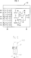
- the FIG. 1 schematically shows a modular safety controller 1, comprising a head module 2, an input extension module 4 and an output extension module 6, which are connected to each other via a backplane bus 8 data side.
- a central control unit 10 is arranged, which processes the input signals and generates output signals.
- the safety controller 1 is a programmable logic controller, which additionally in accordance with the standard EN ISO 13849-1 designed, that is functionally safe. This is ensured, among other measures, by the so-called monitored redundancy, ie the control unit 2 comprises two redundantly operating microcontrollers (not shown in more detail) whose results are permanently adjusted and checked for conformity.
- the safety controller 1 has a multiplicity of terminals 12-38, of which six terminals 12-22 are arranged on the head module 2, four terminals 24-30 on the input extension module 4 and four terminals 32-38 on the output extension module 6.
- the control unit 10 can control or retrieve each of the terminals 12-38 via the backplane bus 8 and possibly further processor units in the expansion modules 4, 6.
- the terminals 32-38 of the output expansion module 6 can be switched in pairs in the power supply to an actuator not shown in detail, which switches an electrical load, which has the potential hazard and should therefore be safely switched off.
- an actuator not shown in detail, which switches an electrical load, which has the potential hazard and should therefore be safely switched off.
- two relays 40, 42 and 44, 46 connected in series.
- both relays 40, 42 and 44, 46 must be in the closed state, so they are redundant.
- the relays 40, 42 and 44, 46 are independently controlled by the redundant microcontrollers of the control unit 10.
- FIG. 2 In order to interrupt or at least to influence the function of the electrical consumer in the event of danger, various examples are given below FIG. 2 but not in the FIG. 1 encoder shown connected to the safety controller 1. These can be, for example, emergency stop switches, light barriers, door position switches, etc.
- the safety controller 1 in addition to the terminals 24 - 30 on the input expansion module 4 and terminals 12 - 22, which can provide the encoder with power.
- a small positive DC voltage is always present in the exemplary embodiment, but this is not mandatory, for example in so-called open-collector or tri-state outputs.
- test signals with cyclic, pulse-like test pulses for line and short circuit testing may be provided, each set for a short duration of 0 volts above the ground voltage otherwise obtained.
- the test pulses may be delivered to a trigger such as a manual or automatic initiated check request.
- All terminals 12-38 can be configured arbitrarily on the hardware side, eg as screwed or spring terminals.
- FIG. 2 shows an example of application of the safety controller 1 in Gut gleich. For reasons of clarity, the representation of all parts of the safety controller 1 is dispensed with and only a section of the safety controller is shown.
- FIG. 2 shows an emergency stop switch 48 comprising two redundant channels with two mechanically connected switches 50, 52.
- the switches 50, 52 are equivalent, ie both are closed in the good state and opened in the state of the request of the safety function.
- the emergency stop switch 48 is connected to the safety controller 1 in such a way that terminal 16 is connected to terminal 26 via one of the switches 50, terminal 14 via the other the switch 52 to terminal 24.
- terminal 26 results
- the signal combination Plus, Plus in the state of the request of the safety function, the signal combination Zero zero.
- Other signal combinations indicate an error.
- an interruption of the power supply of each of the explained by the logic programming below with the emergency stop switch 48 associated circuit in the output extension module 6 causes, for example, between the terminals 36 and 38th
- the example in the 1 and 2 serves only to illustrate the operation of the safety controller 1 and is therefore greatly simplified.
- the system will be far more complex, that is, there will be significantly more modules and modules of a different kind (eg, so-called gateway modules for interfaces to fieldbuses), and there will be a variety of other terminals on different modules, a variety can switch from electrical consumers and to a variety of encoders and actuators of various kinds can be connected.
- the clamps do not necessarily have to fulfill only one function but can optionally also be used variably as input or output terminals.
- the terminal assignment and thus ultimately expected at the terminals signal combinations and the logical link between the encoder and actuator signals must be stored in the control unit 10 of the safety controller 1, so that this causes the appropriate electrical signaling shutdown the right electrical consumers. This is done by transferring a corresponding configuration to a stored in the control unit 10 firmware. Since the configuration ultimately the entire logical links between encoders and actuators In the following, it will be referred to as a program for simplicity's sake.
- the creation of this program is done on a digital computer 54, which in FIG. 3 is shown.
- the computer 54 has input devices such as a keyboard 56 and a mouse 58 and a screen 60 as an output device. It is connected to the safety controller 1 via a serial or parallel interface or eg via Ethernet.
- the program is created, tested and then transmitted to the control unit 10 of the safety controller 1 by a user on a graphical programming interface on the basis of the intended encoder and actuator combination and the desired logical link.
- the digital computer 54 may be configured as a tablet with touchscreen. Insofar as in the following example in the embodiment of mouse click or mouse movement is spoken, this would be done in the case of a tablet by tapping and corresponding pulling the finger.
- Such a programming surface 62 shown on a screen 60 is shown in FIG FIG. 4 shown.
- the programming interface 62 has a first subarea 64, in which function blocks 66, 68, 70 are shown.
- the function blocks 66, 68, 70 are grouped into three groups.
- the first group comprises function blocks 66 to each of which an encoder is assigned, eg emergency stop switch single-channel, emergency stop switch dual-channel etc.
- These function blocks 66 symbolize an input signal of such a transmitter, wherein in the logic programming the hardware implemented redundancy (see above) is no longer apparent to the user, since the Error monitoring of the firmware of the safety controller 1 is done even without separate programming itself.
- the user should only define how the operation of such an encoder works. So at the in FIG. 2 Although the two-channel emergency stop switch shown, although it actually comprises two redundant channels, in the logic programming on the programming interface 62 only a single output signal is displayed, which is then further linked in the logic.
- the second group of function blocks 68 comprises symbols which symbolize output signals to actuators.
- the above is analogous here.
- the third group includes functional blocks 70, which are logic devices. These can be simple logical combinations such as “AND” or “OR”, more complex evaluators such as flip-flops, clock generators or application-specific function blocks 70 for switch-off delays, presses, etc.
- the function blocks 66, 68, 70 also for further content Be subdivided criteria.
- the user now selects a function block 66, 68, 70 as part of the logic programming.
- the selection is made by moving the mouse pointer not shown in detail to the desired function block 66, 68, 70 and a simple mouse click on the respective desired function block 66, 68, 70.
- the selection by mouse click results in an instance 72-84 of the function block 66, 68, 70 is generated, which is attached to the mouse pointer.
- the instance 72-84 is generated because a plurality of similar functional blocks 66, 68, 70 may be needed and therefore If necessary, the same function block 66, 68, 70 must be selected several times in succession.
- the instance 72-84 may in this case be identical to the function block 66, 68, 70, but this need not be.
- the instances 72-84 are significantly wider and flatter than the function block 66, 68, 70 in order to possibly display text thereon. If the function block 66, 68, 70 contains a characteristic pictogram, this pictogram can also be displayed in embodiments on the instance 72-84, if necessary enlarged or reduced.
- a logic circuit diagram 88 is shown in the second subarea 86 of the programming interface 62, created by the programmer with the aid of the instances 72-84.
- programming is performed using graphical symbols that are logically linked by a line trace.
- Input signals from encoders, represented by instances 72, 74, 76 from the function block symbols 66, are processed by logic blocks in the instances 78, 80 and processed into output signals for actuators, represented by instance 84.
- the depositing of the instances 72-84 takes place after selection of the function blocks 66, 68, 70 (see above) by means of a simple drag-drop procedure.
- each function block 66, 68, 70 By simply connecting the signal inputs and outputs of each function block 66, 68, 70 to lines 90-100, the signals can be routed as desired.
- a logic diagram 88 is thus generated, which defines the switching logic.
- the terminal assignments are defined, ie for those function blocks 66, 68, 70 which receive direct signals from physical input terminals or such signals to generate for physical output terminals of the safety controller 1 is determined by a corresponding assignment of a terminal name, from which terminal the corresponding signal is received or to which terminal it is to be sent.
- the analog module 102 is connected to the other modules 2, 4, 6 on the backplane bus 8 data side. It has four terminals 104-110 as signal inputs for analog signals. That is, terminals 104-110 are not suitable for processing e.g. +24 V signals or test pulses, but rather e.g. Record current or voltage values from analog sensors such as temperature sensors or similar. be generated.
- the air mass flow and the gas mass flow should be checked by means of the analog module 102 and the safety controller 1 to a burner.
- the standard EN 746-2 here requires that the air mass flow to the Gas mass flow must always be in a ratio that can be safely ignited and ensures stable and safe combustion at each burner over the entire operating range. Faults or malfunctions should cause the system to prone to excess air or cause a lockout if the air / gas ratio results in a non-safe condition.
- terminals 104 - 110 which can measure mass flows to the burner.
- terminals 104 and 106 Connected to terminals 104 and 106 are (redundant) sensors that measure the mass air flow to the burner.
- terminals 108 and 110 are connected (also redundant) sensors which measure the gas mass flow to the burner. All sensors output a signal proportional to the mass flow, in the exemplary embodiment a current between 4 and 20 mA. As a result, the mass flow of gas and air are redundantly available to the safety controller 1 via the analog module 102.
- FIG. 6 1 shows a section of the right-hand area 86 of the programming interface 62 into which two instances 112, 114 of these function block symbols have been drawn.
- the first instance 112 has been parameterized to evaluate the signals detected at terminals 104, 106, ie the mass air flow.
- the second instance 114 was parameterized to evaluate the signals detected at terminals 108, 110, ie the gas mass flow.
- the hardware redundancy provided by the duplicate sensors is no longer apparent to the user because error monitoring, i. a deviation of the respective two redundant channels from the redundant sensors, is performed by the firmware of the safety controller 1 itself.
- the outputs 116, 118 of the instances 112, 114 thus provide only the analog value of the measured variable for programming, i. here 4 - 20 mA.
- the hardware-side redundancy shown is only required for particularly high security categories. For lower security categories, simple signaling with only one sensor at a time can be sufficient.
- the above and other applications are covered in FIG. 6 as an instance 120 shown function block from, in the following closer
- the function module has two inputs 122, 124 which are connected to the outputs 116, 118 of the instances 112, 114 by lines 126, 128, respectively.
- the signals of the analog sensors are thus fed to the inputs 122, 124 and processed in the instance 120 of the function block.
- the function block forms a ratio Ia1 / Ia2 of the signals at the inputs 122, 124.
- the instance 120 can be parameterized with two ratios n1 / n2 and n3 / n4, which form a window within which a digital signal representing a good state, e.g. HIGH or 1.
- This digital signal can then be further processed in the logic diagram 88 by combining it with other function blocks.
- the values n1-n4 are given here as positive integers.
- the instance 120 can also only be parameterized for a ratio n1 / n2 to overflow or underflow, i. that when the parameterized ratio is exceeded or fallen below by the ratio Ia1 / Ia2 from the instances 112, 114, the good state is removed and a digital signal is output at the output, which represents a bad state, e.g. LOW or 0.
- a hysteresis value can be parameterized.
- the hysteresis value is given as a percentage of the parameterized ratio.
- the set ratio corresponds to 100%.
- the hysteresis value avoids that, as soon as the ratio returns to the good range, a good state is immediately output at the output 126.
- the ratio must have a distance defined by the hysteresis value to the defined ratio n1 / n2 or n3 / n4.
- a hysteresis of 10% is parameterised, resulting in a correction value of 0.05. This means that when the overshoot is configured, it is turned off at a ratio of 0.5, i. a bad state is output at the output 126.
- the sensors for the first temperature at the terminals 104, 106 are hereby temperature-current sensors which output currents of 0-20 mA, which correspond linearly to temperatures of 100-230 ° C.
- resistance thermometers are connected, which can measure temperatures of 50-200 ° C. This information is stored in the instance 120.
- the plausibility check of the function module now checks whether in fact, the higher ratio has been configured as overshoot and the lower ratio as underrun. This is the case here, otherwise an error would be output. Therefore, the device is now configured to output a good state at output 126 when the ratio of inputs 122, 124 is between 0.25 and 0.8.
- a hysteresis value can be defined, as described above.
- the function block also has a digital input 128 for muting, i. for shutdown suppression, which is also time-limited. Furthermore, the function block has a digital input 130 for reset. If a HIGH signal is present here, the instance 120 is reset.
- the function module has two outputs which, in the case of an error, e.g. Error detection within the redundancy, or in a warning each output a HIGH signal.
- an error e.g. Error detection within the redundancy
- a warning each output a HIGH signal.
Landscapes
- Physics & Mathematics (AREA)
- General Physics & Mathematics (AREA)
- Engineering & Computer Science (AREA)
- Automation & Control Theory (AREA)
- Safety Devices In Control Systems (AREA)
Priority Applications (2)
| Application Number | Priority Date | Filing Date | Title |
|---|---|---|---|
| EP18168274.1A EP3557338B1 (fr) | 2018-04-19 | 2018-04-19 | Procédé de programmation d'une commande de sécurité |
| ES18168274T ES2929014T3 (es) | 2018-04-19 | 2018-04-19 | Procedimiento para programar un control de seguridad |
Applications Claiming Priority (1)
| Application Number | Priority Date | Filing Date | Title |
|---|---|---|---|
| EP18168274.1A EP3557338B1 (fr) | 2018-04-19 | 2018-04-19 | Procédé de programmation d'une commande de sécurité |
Publications (2)
| Publication Number | Publication Date |
|---|---|
| EP3557338A1 true EP3557338A1 (fr) | 2019-10-23 |
| EP3557338B1 EP3557338B1 (fr) | 2022-09-21 |
Family
ID=62044507
Family Applications (1)
| Application Number | Title | Priority Date | Filing Date |
|---|---|---|---|
| EP18168274.1A Active EP3557338B1 (fr) | 2018-04-19 | 2018-04-19 | Procédé de programmation d'une commande de sécurité |
Country Status (2)
| Country | Link |
|---|---|
| EP (1) | EP3557338B1 (fr) |
| ES (1) | ES2929014T3 (fr) |
Citations (2)
| Publication number | Priority date | Publication date | Assignee | Title |
|---|---|---|---|---|
| US20040199364A1 (en) * | 2003-04-01 | 2004-10-07 | Gary Law | Coordination of field device operations with overrides and bypasses within a process control and safety system |
| DE102009011679A1 (de) * | 2009-02-23 | 2010-08-26 | Pilz Gmbh & Co. Kg | Verfahren und Vorrichtung zum Erstellen eines Anwenderprogrammes für eine Sicherheitssteuerung |
-
2018
- 2018-04-19 ES ES18168274T patent/ES2929014T3/es active Active
- 2018-04-19 EP EP18168274.1A patent/EP3557338B1/fr active Active
Patent Citations (2)
| Publication number | Priority date | Publication date | Assignee | Title |
|---|---|---|---|---|
| US20040199364A1 (en) * | 2003-04-01 | 2004-10-07 | Gary Law | Coordination of field device operations with overrides and bypasses within a process control and safety system |
| DE102009011679A1 (de) * | 2009-02-23 | 2010-08-26 | Pilz Gmbh & Co. Kg | Verfahren und Vorrichtung zum Erstellen eines Anwenderprogrammes für eine Sicherheitssteuerung |
Non-Patent Citations (2)
| Title |
|---|
| ANONYMOUS: "User Manual for PLC Programming with CoDeSys 2.3", 1 January 2005 (2005-01-01), XP055508467, Retrieved from the Internet <URL:http://www.deltaelektronik.dk/DVD/Produkter/Infranor/Manual/Cybelec/ELITE-HMI/CoDeSys_V23_Programmering.pdf> [retrieved on 20180920] * |
| KLAUS KRONER ET AL: "Luft/Gas-Verhältnisregelung an industriellen Beheizungseinrichtungen", GASWÄRME INTERNATIONAL (55) NR. 4/2006, 1 April 2006 (2006-04-01), pages 263 - 269, XP055508470, Retrieved from the Internet <URL:https://docuthek.kromschroeder.com/documents/download.php?lang=de&doc=14877> [retrieved on 20180920] * |
Also Published As
| Publication number | Publication date |
|---|---|
| ES2929014T3 (es) | 2022-11-24 |
| EP3557338B1 (fr) | 2022-09-21 |
Similar Documents
| Publication | Publication Date | Title |
|---|---|---|
| EP2399174B1 (fr) | Procédé et dispositif pour réaliser un programme d'application pour une commande de sécurité | |
| EP3069202B1 (fr) | Commande de sécurité à entrées configurables | |
| EP2367083B1 (fr) | Dispositif de création d'un programme pour une commande programmable par mémoire, dispositif de programmation et procédé de programmation d'une commande programmable par mémoire | |
| EP2363770B1 (fr) | Dispositif de sécurité doté d'un contrôleur configurable | |
| EP2715462B1 (fr) | Procédé pour faire fonctionner un appareil de commande de sécurité | |
| EP1695055B1 (fr) | Dispositif de mesure, en particulier convertisseur de mesure de temperature | |
| EP1860513A2 (fr) | Circuit destiné à la transmission sécurisée d'une valeur de signal analogique | |
| DE102009019089A1 (de) | Verfahren und Vorrichtung zum Erstellen eines Anwenderprogramms für eine Sicherheitssteuerung | |
| DE102017126754B4 (de) | Eingangsschaltung zum fehlersicheren Einlesen eines analogen Eingangssignals | |
| EP1932007B1 (fr) | Dispositif et procede d'evaluation a securite integree d'un transmetteur de position, en particulier d'un potentiometre | |
| DE112008003195T5 (de) | Elektrischer Schaltkreis mit einem physikalischen Übertragungsschicht-Diagnosesystem | |
| EP2098928A1 (fr) | Procédé et dispositif adaptés à la programmation et/ou la configuration d'un contrôleur de sécurité | |
| EP2701019B1 (fr) | Procédé de paramétrage d'un appareil de terrain, appareil de terrain correspondant et système de paramétrage | |
| EP1364459B1 (fr) | Dispositif de commutation de securite | |
| DE102008045590B3 (de) | Bussystem | |
| DE102019116193A1 (de) | Feldgerät der Automatisierungstechnik | |
| EP4432034B1 (fr) | Procédé et système de détection d'une configuration d'un contrôleur de sécurité modulaire | |
| EP1683016B1 (fr) | Acquisition fiable de donnees d'entree | |
| EP3557338B1 (fr) | Procédé de programmation d'une commande de sécurité | |
| EP3451089B1 (fr) | Procédé de programmation assistée par ordinateur d'une commande par programme enregistré | |
| EP3343301B1 (fr) | Procédé de programmation d'une commande de sécurité | |
| EP2965157B1 (fr) | Procédé et dispositif permettant de faire fonctionner une installation de traitement et/ou de fabrication | |
| EP3396480B1 (fr) | Procédé de programmation d'un dispositif de sécurité | |
| EP3832453A1 (fr) | Procédé de mise en uvre d'une arithmétique en virgule flottante | |
| EP2887164B1 (fr) | Procédé destiné à la programmation d'une commande de sécurité |
Legal Events
| Date | Code | Title | Description |
|---|---|---|---|
| PUAI | Public reference made under article 153(3) epc to a published international application that has entered the european phase |
Free format text: ORIGINAL CODE: 0009012 |
|
| STAA | Information on the status of an ep patent application or granted ep patent |
Free format text: STATUS: THE APPLICATION HAS BEEN PUBLISHED |
|
| AK | Designated contracting states |
Kind code of ref document: A1 Designated state(s): AL AT BE BG CH CY CZ DE DK EE ES FI FR GB GR HR HU IE IS IT LI LT LU LV MC MK MT NL NO PL PT RO RS SE SI SK SM TR |
|
| AX | Request for extension of the european patent |
Extension state: BA ME |
|
| STAA | Information on the status of an ep patent application or granted ep patent |
Free format text: STATUS: REQUEST FOR EXAMINATION WAS MADE |
|
| 17P | Request for examination filed |
Effective date: 20200423 |
|
| RBV | Designated contracting states (corrected) |
Designated state(s): AL AT BE BG CH CY CZ DE DK EE ES FI FR GB GR HR HU IE IS IT LI LT LU LV MC MK MT NL NO PL PT RO RS SE SI SK SM TR |
|
| STAA | Information on the status of an ep patent application or granted ep patent |
Free format text: STATUS: EXAMINATION IS IN PROGRESS |
|
| 17Q | First examination report despatched |
Effective date: 20201208 |
|
| GRAP | Despatch of communication of intention to grant a patent |
Free format text: ORIGINAL CODE: EPIDOSNIGR1 |
|
| STAA | Information on the status of an ep patent application or granted ep patent |
Free format text: STATUS: GRANT OF PATENT IS INTENDED |
|
| INTG | Intention to grant announced |
Effective date: 20220511 |
|
| GRAS | Grant fee paid |
Free format text: ORIGINAL CODE: EPIDOSNIGR3 |
|
| GRAA | (expected) grant |
Free format text: ORIGINAL CODE: 0009210 |
|
| STAA | Information on the status of an ep patent application or granted ep patent |
Free format text: STATUS: THE PATENT HAS BEEN GRANTED |
|
| AK | Designated contracting states |
Kind code of ref document: B1 Designated state(s): AL AT BE BG CH CY CZ DE DK EE ES FI FR GB GR HR HU IE IS IT LI LT LU LV MC MK MT NL NO PL PT RO RS SE SI SK SM TR |
|
| REG | Reference to a national code |
Ref country code: GB Ref legal event code: FG4D Free format text: NOT ENGLISH |
|
| REG | Reference to a national code |
Ref country code: CH Ref legal event code: EP |
|
| REG | Reference to a national code |
Ref country code: IE Ref legal event code: FG4D Free format text: LANGUAGE OF EP DOCUMENT: GERMAN |
|
| REG | Reference to a national code |
Ref country code: DE Ref legal event code: R096 Ref document number: 502018010657 Country of ref document: DE |
|
| REG | Reference to a national code |
Ref country code: AT Ref legal event code: REF Ref document number: 1520240 Country of ref document: AT Kind code of ref document: T Effective date: 20221015 |
|
| REG | Reference to a national code |
Ref country code: ES Ref legal event code: FG2A Ref document number: 2929014 Country of ref document: ES Kind code of ref document: T3 Effective date: 20221124 |
|
| REG | Reference to a national code |
Ref country code: LT Ref legal event code: MG9D |
|
| REG | Reference to a national code |
Ref country code: NL Ref legal event code: MP Effective date: 20220921 |
|
| PG25 | Lapsed in a contracting state [announced via postgrant information from national office to epo] |
Ref country code: SE Free format text: LAPSE BECAUSE OF FAILURE TO SUBMIT A TRANSLATION OF THE DESCRIPTION OR TO PAY THE FEE WITHIN THE PRESCRIBED TIME-LIMIT Effective date: 20220921 Ref country code: RS Free format text: LAPSE BECAUSE OF FAILURE TO SUBMIT A TRANSLATION OF THE DESCRIPTION OR TO PAY THE FEE WITHIN THE PRESCRIBED TIME-LIMIT Effective date: 20220921 Ref country code: NO Free format text: LAPSE BECAUSE OF FAILURE TO SUBMIT A TRANSLATION OF THE DESCRIPTION OR TO PAY THE FEE WITHIN THE PRESCRIBED TIME-LIMIT Effective date: 20221221 Ref country code: LV Free format text: LAPSE BECAUSE OF FAILURE TO SUBMIT A TRANSLATION OF THE DESCRIPTION OR TO PAY THE FEE WITHIN THE PRESCRIBED TIME-LIMIT Effective date: 20220921 Ref country code: LT Free format text: LAPSE BECAUSE OF FAILURE TO SUBMIT A TRANSLATION OF THE DESCRIPTION OR TO PAY THE FEE WITHIN THE PRESCRIBED TIME-LIMIT Effective date: 20220921 Ref country code: FI Free format text: LAPSE BECAUSE OF FAILURE TO SUBMIT A TRANSLATION OF THE DESCRIPTION OR TO PAY THE FEE WITHIN THE PRESCRIBED TIME-LIMIT Effective date: 20220921 |
|
| PG25 | Lapsed in a contracting state [announced via postgrant information from national office to epo] |
Ref country code: HR Free format text: LAPSE BECAUSE OF FAILURE TO SUBMIT A TRANSLATION OF THE DESCRIPTION OR TO PAY THE FEE WITHIN THE PRESCRIBED TIME-LIMIT Effective date: 20220921 Ref country code: GR Free format text: LAPSE BECAUSE OF FAILURE TO SUBMIT A TRANSLATION OF THE DESCRIPTION OR TO PAY THE FEE WITHIN THE PRESCRIBED TIME-LIMIT Effective date: 20221222 |
|
| PG25 | Lapsed in a contracting state [announced via postgrant information from national office to epo] |
Ref country code: SM Free format text: LAPSE BECAUSE OF FAILURE TO SUBMIT A TRANSLATION OF THE DESCRIPTION OR TO PAY THE FEE WITHIN THE PRESCRIBED TIME-LIMIT Effective date: 20220921 Ref country code: RO Free format text: LAPSE BECAUSE OF FAILURE TO SUBMIT A TRANSLATION OF THE DESCRIPTION OR TO PAY THE FEE WITHIN THE PRESCRIBED TIME-LIMIT Effective date: 20220921 Ref country code: PT Free format text: LAPSE BECAUSE OF FAILURE TO SUBMIT A TRANSLATION OF THE DESCRIPTION OR TO PAY THE FEE WITHIN THE PRESCRIBED TIME-LIMIT Effective date: 20230123 Ref country code: CZ Free format text: LAPSE BECAUSE OF FAILURE TO SUBMIT A TRANSLATION OF THE DESCRIPTION OR TO PAY THE FEE WITHIN THE PRESCRIBED TIME-LIMIT Effective date: 20220921 |
|
| PGFP | Annual fee paid to national office [announced via postgrant information from national office to epo] |
Ref country code: FR Payment date: 20230125 Year of fee payment: 6 |
|
| PG25 | Lapsed in a contracting state [announced via postgrant information from national office to epo] |
Ref country code: SK Free format text: LAPSE BECAUSE OF FAILURE TO SUBMIT A TRANSLATION OF THE DESCRIPTION OR TO PAY THE FEE WITHIN THE PRESCRIBED TIME-LIMIT Effective date: 20220921 Ref country code: PL Free format text: LAPSE BECAUSE OF FAILURE TO SUBMIT A TRANSLATION OF THE DESCRIPTION OR TO PAY THE FEE WITHIN THE PRESCRIBED TIME-LIMIT Effective date: 20220921 Ref country code: IS Free format text: LAPSE BECAUSE OF FAILURE TO SUBMIT A TRANSLATION OF THE DESCRIPTION OR TO PAY THE FEE WITHIN THE PRESCRIBED TIME-LIMIT Effective date: 20230121 Ref country code: EE Free format text: LAPSE BECAUSE OF FAILURE TO SUBMIT A TRANSLATION OF THE DESCRIPTION OR TO PAY THE FEE WITHIN THE PRESCRIBED TIME-LIMIT Effective date: 20220921 |
|
| REG | Reference to a national code |
Ref country code: DE Ref legal event code: R097 Ref document number: 502018010657 Country of ref document: DE |
|
| PG25 | Lapsed in a contracting state [announced via postgrant information from national office to epo] |
Ref country code: NL Free format text: LAPSE BECAUSE OF FAILURE TO SUBMIT A TRANSLATION OF THE DESCRIPTION OR TO PAY THE FEE WITHIN THE PRESCRIBED TIME-LIMIT Effective date: 20220921 Ref country code: AL Free format text: LAPSE BECAUSE OF FAILURE TO SUBMIT A TRANSLATION OF THE DESCRIPTION OR TO PAY THE FEE WITHIN THE PRESCRIBED TIME-LIMIT Effective date: 20220921 |
|
| P01 | Opt-out of the competence of the unified patent court (upc) registered |
Effective date: 20230530 |
|
| PLBE | No opposition filed within time limit |
Free format text: ORIGINAL CODE: 0009261 |
|
| STAA | Information on the status of an ep patent application or granted ep patent |
Free format text: STATUS: NO OPPOSITION FILED WITHIN TIME LIMIT |
|
| PG25 | Lapsed in a contracting state [announced via postgrant information from national office to epo] |
Ref country code: DK Free format text: LAPSE BECAUSE OF FAILURE TO SUBMIT A TRANSLATION OF THE DESCRIPTION OR TO PAY THE FEE WITHIN THE PRESCRIBED TIME-LIMIT Effective date: 20220921 |
|
| PGFP | Annual fee paid to national office [announced via postgrant information from national office to epo] |
Ref country code: ES Payment date: 20230517 Year of fee payment: 6 |
|
| 26N | No opposition filed |
Effective date: 20230622 |
|
| PG25 | Lapsed in a contracting state [announced via postgrant information from national office to epo] |
Ref country code: SI Free format text: LAPSE BECAUSE OF FAILURE TO SUBMIT A TRANSLATION OF THE DESCRIPTION OR TO PAY THE FEE WITHIN THE PRESCRIBED TIME-LIMIT Effective date: 20220921 |
|
| REG | Reference to a national code |
Ref country code: CH Ref legal event code: PL |
|
| PG25 | Lapsed in a contracting state [announced via postgrant information from national office to epo] |
Ref country code: LU Free format text: LAPSE BECAUSE OF NON-PAYMENT OF DUE FEES Effective date: 20230419 |
|
| REG | Reference to a national code |
Ref country code: BE Ref legal event code: MM Effective date: 20230430 |
|
| PG25 | Lapsed in a contracting state [announced via postgrant information from national office to epo] |
Ref country code: MC Free format text: LAPSE BECAUSE OF FAILURE TO SUBMIT A TRANSLATION OF THE DESCRIPTION OR TO PAY THE FEE WITHIN THE PRESCRIBED TIME-LIMIT Effective date: 20220921 |
|
| PG25 | Lapsed in a contracting state [announced via postgrant information from national office to epo] |
Ref country code: MC Free format text: LAPSE BECAUSE OF FAILURE TO SUBMIT A TRANSLATION OF THE DESCRIPTION OR TO PAY THE FEE WITHIN THE PRESCRIBED TIME-LIMIT Effective date: 20220921 Ref country code: LI Free format text: LAPSE BECAUSE OF NON-PAYMENT OF DUE FEES Effective date: 20230430 Ref country code: CH Free format text: LAPSE BECAUSE OF NON-PAYMENT OF DUE FEES Effective date: 20230430 |
|
| REG | Reference to a national code |
Ref country code: IE Ref legal event code: MM4A |
|
| PG25 | Lapsed in a contracting state [announced via postgrant information from national office to epo] |
Ref country code: BE Free format text: LAPSE BECAUSE OF NON-PAYMENT OF DUE FEES Effective date: 20230430 |
|
| PG25 | Lapsed in a contracting state [announced via postgrant information from national office to epo] |
Ref country code: IE Free format text: LAPSE BECAUSE OF NON-PAYMENT OF DUE FEES Effective date: 20230419 |
|
| PG25 | Lapsed in a contracting state [announced via postgrant information from national office to epo] |
Ref country code: IE Free format text: LAPSE BECAUSE OF NON-PAYMENT OF DUE FEES Effective date: 20230419 |
|
| REG | Reference to a national code |
Ref country code: AT Ref legal event code: MM01 Ref document number: 1520240 Country of ref document: AT Kind code of ref document: T Effective date: 20230419 |
|
| PG25 | Lapsed in a contracting state [announced via postgrant information from national office to epo] |
Ref country code: AT Free format text: LAPSE BECAUSE OF NON-PAYMENT OF DUE FEES Effective date: 20230419 |
|
| PG25 | Lapsed in a contracting state [announced via postgrant information from national office to epo] |
Ref country code: AT Free format text: LAPSE BECAUSE OF NON-PAYMENT OF DUE FEES Effective date: 20230419 |
|
| PG25 | Lapsed in a contracting state [announced via postgrant information from national office to epo] |
Ref country code: BG Free format text: LAPSE BECAUSE OF FAILURE TO SUBMIT A TRANSLATION OF THE DESCRIPTION OR TO PAY THE FEE WITHIN THE PRESCRIBED TIME-LIMIT Effective date: 20220921 |
|
| PG25 | Lapsed in a contracting state [announced via postgrant information from national office to epo] |
Ref country code: BG Free format text: LAPSE BECAUSE OF FAILURE TO SUBMIT A TRANSLATION OF THE DESCRIPTION OR TO PAY THE FEE WITHIN THE PRESCRIBED TIME-LIMIT Effective date: 20220921 |
|
| PG25 | Lapsed in a contracting state [announced via postgrant information from national office to epo] |
Ref country code: FR Free format text: LAPSE BECAUSE OF NON-PAYMENT OF DUE FEES Effective date: 20240430 |
|
| PG25 | Lapsed in a contracting state [announced via postgrant information from national office to epo] |
Ref country code: FR Free format text: LAPSE BECAUSE OF NON-PAYMENT OF DUE FEES Effective date: 20240430 |
|
| REG | Reference to a national code |
Ref country code: ES Ref legal event code: FD2A Effective date: 20250529 |
|
| PGFP | Annual fee paid to national office [announced via postgrant information from national office to epo] |
Ref country code: DE Payment date: 20250430 Year of fee payment: 8 |
|
| PG25 | Lapsed in a contracting state [announced via postgrant information from national office to epo] |
Ref country code: ES Free format text: LAPSE BECAUSE OF NON-PAYMENT OF DUE FEES Effective date: 20240420 |
|
| PGFP | Annual fee paid to national office [announced via postgrant information from national office to epo] |
Ref country code: GB Payment date: 20250430 Year of fee payment: 8 |
|
| PGFP | Annual fee paid to national office [announced via postgrant information from national office to epo] |
Ref country code: IT Payment date: 20250430 Year of fee payment: 8 |
|
| PG25 | Lapsed in a contracting state [announced via postgrant information from national office to epo] |
Ref country code: CY Free format text: LAPSE BECAUSE OF FAILURE TO SUBMIT A TRANSLATION OF THE DESCRIPTION OR TO PAY THE FEE WITHIN THE PRESCRIBED TIME-LIMIT; INVALID AB INITIO Effective date: 20180419 |
|
| PG25 | Lapsed in a contracting state [announced via postgrant information from national office to epo] |
Ref country code: HU Free format text: LAPSE BECAUSE OF FAILURE TO SUBMIT A TRANSLATION OF THE DESCRIPTION OR TO PAY THE FEE WITHIN THE PRESCRIBED TIME-LIMIT; INVALID AB INITIO Effective date: 20180419 |
|
| PG25 | Lapsed in a contracting state [announced via postgrant information from national office to epo] |
Ref country code: TR Free format text: LAPSE BECAUSE OF FAILURE TO SUBMIT A TRANSLATION OF THE DESCRIPTION OR TO PAY THE FEE WITHIN THE PRESCRIBED TIME-LIMIT Effective date: 20220921 |
|
| PLAA | Information modified related to event that no opposition was filed |
Free format text: ORIGINAL CODE: 0009299DELT |
|
| REG | Reference to a national code |
Ref country code: CH Ref legal event code: L10 Free format text: ST27 STATUS EVENT CODE: U-0-0-L10-L00 (AS PROVIDED BY THE NATIONAL OFFICE) Effective date: 20260218 Ref country code: CH Ref legal event code: Y10 Free format text: ST27 STATUS EVENT CODE: U-0-0-Y10-Y00 (AS PROVIDED BY THE NATIONAL OFFICE) Effective date: 20260218 |
|
| PLBE | No opposition filed within time limit |
Free format text: ORIGINAL CODE: 0009261 |
|
| REG | Reference to a national code |
Ref country code: CH Ref legal event code: L10 Free format text: ST27 STATUS EVENT CODE: U-0-0-L10-L00 (AS PROVIDED BY THE NATIONAL OFFICE) Effective date: 20260225 |
|
| D26N | No opposition filed (deleted) | ||
| RIN2 | Information on inventor provided after grant (corrected) |
Inventor name: LAUBSCH, JOERG Inventor name: KIRNER, PETER |
|
| 26N | No opposition filed |
Effective date: 20230622 |
|
| REG | Reference to a national code |
Ref country code: ES Ref legal event code: FD2A Effective date: 20260326 |
|
| REG | Reference to a national code |
Ref country code: ES Ref legal event code: FD2A Effective date: 20260401 |