EP3564545A1 - Composant d'assemblage comprenant un composant et d'un élément doté d'une partie de tête et d'un col disposé sur un côté de la partie de tête ainsi que son procédé de fabrication - Google Patents
Composant d'assemblage comprenant un composant et d'un élément doté d'une partie de tête et d'un col disposé sur un côté de la partie de tête ainsi que son procédé de fabrication Download PDFInfo
- Publication number
- EP3564545A1 EP3564545A1 EP19171239.7A EP19171239A EP3564545A1 EP 3564545 A1 EP3564545 A1 EP 3564545A1 EP 19171239 A EP19171239 A EP 19171239A EP 3564545 A1 EP3564545 A1 EP 3564545A1
- Authority
- EP
- European Patent Office
- Prior art keywords
- component
- collar
- head part
- hole
- notches
- Prior art date
- Legal status (The legal status is an assumption and is not a legal conclusion. Google has not performed a legal analysis and makes no representation as to the accuracy of the status listed.)
- Granted
Links
Images


Classifications
-
- F—MECHANICAL ENGINEERING; LIGHTING; HEATING; WEAPONS; BLASTING
- F16—ENGINEERING ELEMENTS AND UNITS; GENERAL MEASURES FOR PRODUCING AND MAINTAINING EFFECTIVE FUNCTIONING OF MACHINES OR INSTALLATIONS; THERMAL INSULATION IN GENERAL
- F16B—DEVICES FOR FASTENING OR SECURING CONSTRUCTIONAL ELEMENTS OR MACHINE PARTS TOGETHER, e.g. NAILS, BOLTS, CIRCLIPS, CLAMPS, CLIPS OR WEDGES; JOINTS OR JOINTING
- F16B37/00—Nuts or like thread-engaging members
- F16B37/04—Devices for fastening nuts to surfaces, e.g. sheets, plates
- F16B37/06—Devices for fastening nuts to surfaces, e.g. sheets, plates by means of welding or riveting
- F16B37/062—Devices for fastening nuts to surfaces, e.g. sheets, plates by means of welding or riveting by means of riveting
- F16B37/068—Devices for fastening nuts to surfaces, e.g. sheets, plates by means of welding or riveting by means of riveting by deforming the material of the support, e.g. the sheet or plate
-
- F—MECHANICAL ENGINEERING; LIGHTING; HEATING; WEAPONS; BLASTING
- F16—ENGINEERING ELEMENTS AND UNITS; GENERAL MEASURES FOR PRODUCING AND MAINTAINING EFFECTIVE FUNCTIONING OF MACHINES OR INSTALLATIONS; THERMAL INSULATION IN GENERAL
- F16B—DEVICES FOR FASTENING OR SECURING CONSTRUCTIONAL ELEMENTS OR MACHINE PARTS TOGETHER, e.g. NAILS, BOLTS, CIRCLIPS, CLAMPS, CLIPS OR WEDGES; JOINTS OR JOINTING
- F16B37/00—Nuts or like thread-engaging members
- F16B37/04—Devices for fastening nuts to surfaces, e.g. sheets, plates
- F16B37/06—Devices for fastening nuts to surfaces, e.g. sheets, plates by means of welding or riveting
- F16B37/062—Devices for fastening nuts to surfaces, e.g. sheets, plates by means of welding or riveting by means of riveting
- F16B37/065—Devices for fastening nuts to surfaces, e.g. sheets, plates by means of welding or riveting by means of riveting by deforming the material of the nut
- F16B37/067—Devices for fastening nuts to surfaces, e.g. sheets, plates by means of welding or riveting by means of riveting by deforming the material of the nut the material of the nut being deformed by a threaded member generating axial movement of the threaded part of the nut, e.g. blind rivet type
Definitions
- the present invention relates to an assembly component consisting of a component and a component mounted on the element designed as a sliding element, which has a head portion, provided on an end face of the head part component contact surface and disposed within the component contact surface and a projecting from this collar having a cross-sectional shape has, which is not circular. Furthermore, the invention relates to an element which is designed for use in such an assembly component and method for producing such a component assembly.
- the main object of the present invention is to provide an assembly part of the type mentioned above and a suitable element for use in the component assembly and a corresponding manufacturing method, wherein the element is slidably present in the component and therefore can be considered as a displacement element and without accommodating the element in a sheet metal cage to have, whereby the sheet metal cage and the corresponding welding, which is not possible anyway with some components such as composite sheets, can be omitted.
- the element is preferably realized as a press-in element, but it could also be designed as a rivet element.
- the free end of the collar is formed so that it can be folded radially outwards to form a Nietbördel, for example by the forces exerted on the component during mounting. If the element is realized as a rivet element, then the design must be carried out as described in the previous paragraph.
- the collar is also used here with play in a complementary shaped to the cross-sectional shape hole of the component, the collar will have outer surfaces which taper in the direction of said end face of the head part and with respect to the central longitudinal axis of the element and with this an acute angle form, the peripheral component of the component mounting surface adjacent the hole of the component will hineinerarranged in between the collar and the end face of the head part formed notches, but not on the bottom of the notches, creating a free space, which ensures a lateral displacement of the element relative to the component , and an axial separation of the element from the component due to Material overlap of the component material with the collar or the radially outwardly deformed collar is prevented within the notches.
- the collar of the element or the hole in the component with a non-circular cross-section. It is particularly favorable if the collar has an at least substantially polygonal cross-sectional shape, wherein the polygonal cross-sectional shape of the collar and accordingly the polygonal hole of the component is selected from the group triangular, square, pentagonal and hexagonal.
- the cross-sectional shape of the collar and the hole is square, in particular formed with rounded corners.
- the square shape makes it possible to achieve an excellent displacement in two mutually perpendicular directions with respect to the local plane of the component in the region of attachment of the element and the rounded corners ensure that the risk of fatigue cracks in the corners of the hole in the component significantly reduced can be.
- so good anti-rotation properties can be secured so that the element can be unscrewed from the component only with the use of destructive forces.
- Another alternative cross-sectional shape is that the collar has an oval or elliptical shape.
- a cross-sectional shape of the collar or hole would be similar to an ice container having a square or rectangular center region with semi-circular lobes on two opposite sides of the central region. Even such cross-sectional shapes, ie elliptical cross-sectional shape or sigmoidal cross-sectional shape allow good displacement with reduced fatigue and excellent anti-rotation properties.
- the polygonal hole is prefabricated in the component or in the sheet metal part, it can be made so large that the polygonal collar can be used at its free end face, which has the largest transverse dimensions, with play in the polygonal hole.
- a specific compression of the component or of the sheet metal part or sheet material in the edge region of the opening of the polygonal hole on the component contact surface of the head side facing in between the obliquely tapered outer surfaces of the collar and the component contact surface of the head part and the sheet metal contact surface of the element so as to prevent the material from overlapping the collar in the radial direction, thus preventing the element from being pulled out of the panel, but not pushing it radially into the notches so far that the element is held laterally, but so that a lateral distance to the bottoms of the notches still exists, with a free space is created and the lateral displacement of the element is still given, and preferably in all lateral directions.
- the same advantages can be achieved with an elliptical or ice cup-like cross-sectional
- the acute angle between the outer surfaces of the collar and the central longitudinal axis of the element is preferably in the range of about 20 ° to about 40 °. Too small an angle limits the radial displaceability of the element and relieves the Auspressschreib, while a too large angle makes the desired direct clamping of the other sheet metal part difficult to achieve without the head of the element and the head of the screw must be increased undesirably.
- a shape is at least substantially polygonal, this means that the corners between adjacent side surfaces can be rounded, which the fatigue behavior of the component comes to good.
- the head portion of the element is preferably polygonal in cross-section and that with the same number of side surfaces as the cross-sectionally polygonal collar. This simplifies the manufacture of the element by, for example, a cold striking process and ensures that the Blauteilanflage Assembly has a uniform design.
- a head shape having a corresponding cross-sectional shape in a collar with an elliptical or Eisbecherähnlichen cross-sectional shape or it could be chosen in all variants of the collar, a head shape which is circular in cross-section.
- the headboard can be spherically rounded in side view, a shape that can be easily realized by a cold impact method.
- elements with such a shape can also be processed cost-saving in known setting heads of the applicant, which are their customers.
- One way to move the component material radially in the edge region of the polygonal hole is to provide the polygonal collar side facing the head portion at least at the sites of the side surfaces of the polygonal collar with protruding displacement surfaces, which in support of the component on a flat surface or on a die with a flat face and upon the application of pressure to the head portion of the element serve to effect the desired displacement of the component material, the extent of radial displacement of the component material being determined by the volume of the protruding displacement surfaces.
- the volume of the protruding displacement surfaces is determined by the radial and circumferential extent and the axial height thereof.
- the axial height should be kept as small as possible, as this leads to an axial recess in the component abutment surface of the head part opposite side of the component, which can prevent or adversely affect the radial displacement of the element.
- Corresponding displacement surfaces may be provided on the component abutment surface of an element having a different cross-sectional shape, for example, having an elliptical or ice cup-like cross-sectional shape.
- the element according to the invention can either be designed as a nut element and have a central longitudinal passage or as a bolt element with a collar part extending away from the head part in the direction of the shaft part.
- the central longitudinal passage of the nut member may be provided with a threaded cylinder or have a smooth cylindrical bore, which can be converted by means of a thread-cutting or -forming screw to a threaded cylinder.
- the assembly member may be formed so that said side of the header, i. the component abutment surface lies in a plane perpendicular to the central longitudinal axis of the element, and the displacement of the component material otherwise takes place.
- a method according to the invention for producing a component part described above according to the invention can be designed so that a non-circular hole is prefabricated in the component with transverse dimensions greater than the corresponding maximum transverse dimensions of the collar in the region of its free end, so that they are guided into the non-circular hole that the sheet material is displaced from the edge portion of the non-circular hole into the notches formed between the side surfaces of the collar and the component abutting surface of the head portion; wherein the sheet material is not displaced so far that it reaches the bottom of the notches, wherein the lateral displacement of the element is ensured relative to the component, but only so far that an axial separation of the elements of the component due to the material overlap of the sheet material with the non-circular collar is prevented within the notches.
- the prefabricated non-circular hole of the component is provided with a raised edge region on the component contact surface of the head part facing side, wherein during insertion of the collar into the component of the raised edge area by the component contact surface of the head part at the same time Supporting the side facing away from the head part of the component is pressed flat, thereby causing the displacement of the component material in the edge region.
- the edge region of the prefabricated hole of the component which lies in the region of attachment of the element in a plane, by means of displacement surfaces which are provided on the component contact surface of the head part at least in the region of the side surfaces of the collar during insertion of the Collar pressed into the component and by the component abutment surface of the head part with simultaneous support of the underside of the component, thereby causing the displacement of the component material in the edge region in the notches into.
- a press-in element 10 with a head portion 12 and a arranged on one side of the head part, in cross-section at least substantially polygonal collar 14 is shown.
- the outer surfaces 16 of the polygonal collar 14, which is designed for insertion into a corresponding prefabricated polygonal hole 18 of a panel 20, for example, in the Fig. 2A is shown as being tapered toward the underside 22 of the head portion 12 and with respect to the central longitudinal axis 24 of the press-fit element 10 and forming an acute angle ⁇ therewith.
- the underside 22 of the head part 12 forms in this example the component or sheet metal contact surface 21 of the press-in element 10.
- the axial height H of the collar 14 should preferably not exceed the thickness D of the panel 20 in the region of the attachment of the press-fit element 10.
- the side 22 of the head part 12 preferably lies in a plane perpendicular to the central longitudinal axis 24 of the press-in element 10.
- the acute angle ⁇ is preferably in the range of about 20 ° to about 40 °.
- the cross-section of the collar 14 and the polygonal hole 18 are shown as having square corners 26.
- the cross-section of the collar 14 and the shape of the hole 18 are the same, but need not necessarily be square.
- the polygonal hole 18 in the panel 20 may be selected, for example, from the group triangular, square, pentagonal and hexagonal or oval, such as from US 2011/0211932 A1 is known.
- the head part 12 is polygonal in cross-section and indeed with the same polygonal shape as the collar 14th
- FIGS. 2A and 2B show the preferred method to attach the presser 10 to the panel 20.
- the polygonal hole 18 is first prefabricated in a separate operation in the panel and that with transverse dimensions greater than the maximum transverse dimensions of the polygonal collar 14 in the region of its free end face 28, so that it can be guided into the polygonal hole.
- the manufacture of the hole 18 may for example be carried out separately from the attachment of the press-in element in a press, which is in another factory or in another building or elsewhere in the same building, where the pressing of the press-fit takes place.
- the insertion or pressing in of the press-in element 10 can take place even in a press or be performed by means of a robot or using a pair of pliers, in particular a motor-driven pliers.
- the polygonal hole 18 is made in a station of a progressive tool (not shown) while the insertion of the press-fit element is performed in another station of the progressive tool.
- a polygonal hole is punched out in one station of the progressive tool, and in another station a press-fit element is inserted in the polygonal hole made in an earlier working stroke of the press.
- the workpieces ie either individual components 20 or a strip of several initially contiguous workpieces or components 20 (panel), are transported on by a predetermined distance within the progressive tool.
- the pre-punching of the sheet metal part is made so that the hole 18 has obliquely arranged side surfaces 30 which also form an acute angle ⁇ with the central longitudinal axis and converge towards the head portion 12, where ⁇ are chosen to be equal to or different from ⁇ can. Furthermore, ⁇ can also be chosen equal to 0 °.
- the prefabricated hole 18 is surrounded by a protruding lip 32, ie by a raised ring area, which can be produced in the manufacture of the polygonal hole 18 by means of a correspondingly shaped die (not shown).
- the radially inner flank 34 of the lip 32 continues in this example, the inclined side surfaces 30 at the same angle ⁇ .
- the transverse dimensions of the hole 18 at the narrowest point, ie the top in Fig. 2A are compared to the maximum transverse dimensions of the collar 14, ie below in Fig. 2A dimensioned slightly larger, so that the collar 14 can be preferably inserted into the prefabricated hole 18 at least substantially free of play.
- the sheet material is not displaced so far that it extends to the bottom 39 of the notches, but it remains a space 41 between the flat pressed lips 32 'and the bottom 39 of the notches 38.
- the lateral displacement of the press-10 is relative to Table 20 guarantees.
- the displacement occurs so far that an axial separation of the press-in element 10 from the panel 20 due to the material overlap of the sheet material or the lip 32 'is prevented with the polygonal collar 14 within the notches 38.
- the term material overlap is meant here that the smallest transverse dimensions of the hole 18, here in the region of the top of the flattened lip 32 ', are smaller than the maximum transverse dimensions of the undeformed collar 14, whereby a withdrawal of the nut member 10 from the sheet metal part 20 or a pressing out of the nut member 19 is prevented from the sheet metal part 20 and is possible only with deforming forces. A movement of the presser further down in Fig. 2B is therefore not possible because the component abutment surface 21, which is larger than the hole 182, prevents such movement.
- the free end face 28 of the collar 14 reaches at most only to the underside 40 of the sheet-metal part 20 and preferably slightly protrudes in front of the underside 40 of the sheet metal part 20, for example by 0.02 mm.
- the desired direct clamping between the sheet metal part 20 and a further sheet metal part or a housing is first achieved, which takes place on the sheet metal part 20 by means of a bolt screwed into the nut member (not shown).
- the further component is held movable relative to the sheet metal part 20, which would be the case if the axial height of the collar 14 were greater than the thickness of the sheet metal part 20.
- the axial height of the collar 14 is greater should be than the thickness of the sheet metal part 20 to overcome the corresponding disadvantages of a specially shaped disc.
- this is a major complication because an extra part would be required.
- the head part 12 of the press-in element 10 and the screw-on element would possibly have to be made larger than would otherwise be necessary.
- the lip 32 is flattened to produce the above-mentioned material overlap prior to attaching the further component and therefore also a transportable assembly member, this is not mandatory. It would be conceivable, for example, for the lip 32 to be flattened only when the further component is screwed on by the force of the corresponding screw bolt.
- the prefabricated polygonal hole 18 of the panel 20 is provided with a raised edge region (lip) 32 on the component abutment surface 21 of the head portion 12 facing side 46, and upon insertion of the collar 14 in the Panel 20, the raised edge portion 32 (ie, the lip 32) is pressed flat or compressed by said side 22 of the head portion while supporting the underside 40 of the panel 20, thereby causing the displacement of the panel material in the edge region.
- FIGS Figs. 3A to 3C . 4A and 4B An alternative design of the press-in element 10 and of the method for attaching the press-in element into the sheet metal part 20 will now be described with reference to FIGS Figs. 3A to 3C . 4A and 4B explained.
- Parts or features having the same shape or function as the previous design according to Fig. 1A to 1C and 2A and 2B are given the same reference numerals and it is understood that the same description applies to these reference numerals as before, unless otherwise stated.
- This convention also applies to the other embodiments and only parts or features that differ in their form or function from the previous parts or features are described separately.
- the press-in element 10 differs from the previous element only in that the polygonal collar 14 facing side 22 of the head part at least at the locations of the side surfaces 16 of the polygonal collar 14 projecting displacement surfaces 42 which provided for the displacement of sheet material in the edge region of the polygonal hole 18 wherein the displaced sheet material flows radially into the notches 38 formed between the side surfaces 16 of the polygonal collar 14 and the side 22 of the head 12 and the displacement surfaces 42, respectively, and prevents axial separation of the press-fit element 10 and the panel 20 or sheet metal part , Another difference to the design according to FIGS. 2A and 2B is to be seen in that FIGS.
- the side walls 30 of the polygonal hole 18 are perpendicular to the top 46 and the bottom 40 of the sheet metal part 20 here, ie the angle ⁇ is equal to zero. Nevertheless, the displacement of the sheet material in the area around the polygonal hole 18 is sufficient to form the lip 32 'and ensure the above-mentioned material overlap.
- the lip 32 ' can be formed by the exertion of pressure on the upper end face 36 of the head portion of the press-in 10 with simultaneous support of the sheet metal part 20 on its underside 40, which has the disadvantage that the impression of the displacement surfaces 42 in the top of the Sheet metal part of the simple radial displacement of the press-fit can be a hindrance, but not completely prevent, especially the press-in element also has a certain axial displaceability. Again, however, it is not absolutely necessary to attach the press-in element captive on the sheet metal part 20 before the further component (not shown) is attached.
- the displacement of the sheet material could be effected by the displacement surfaces 42 only when screwing the other sheet metal part by the force of the corresponding screw, which is screwed into the internal thread 44 of the female press-10.
- the lateral displacement of the press-in element is given in full measure.
- the side surfaces 30 of the polygonal hole can be converged at an acute angle ⁇ to the central longitudinal axis and in the direction of the head portion 12 of the press-in element 10 (as in the example according to FIGS Figs. 5A and 5B is shown).
- the side surfaces 30 of the polygonal hole 18 are arranged convergent at an acute angle ⁇ to the central longitudinal axis and in the direction of the head part 12 of the press-in element 10, wherein the upper side 46 of the sheet metal part 20 lies in one plane, at least in the region of the attachment of the press-in element 10.
- the lip 32 ' is generated by the displacement of the sheet material on the underside 40 of the sheet metal part 20.
- this is done by a die 48 having an annular protrusion 50 which generates a correspondingly shaped annular recess 52 in the bottom of the sheet metal part 20.
- annular recess 52 could also discrete recesses, which are arranged in a ring in the bottom 40 of the sheet metal part 20 around the polygonal hole 18 around, can be used.
- the die 48 must have corresponding discrete protrusions (not shown but in the shape corresponding to the cross section of the annular protrusion 50) responsible for displacing the sheet material at 32 'into the notches 38. This displacement takes place when the sheet metal part between the surface 22 of the head part and the die 48 is squeezed by pressure on the upper end face 36 of the head part, for example in a press.
- the press-in element has been realized as a nut element with a centrally arranged threaded cylinder or internal thread 44.
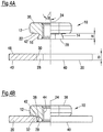
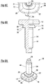
- the press-in element 10 could also be realized as a bolt element 10, as in the FIGS. 6A to 6C . 7A and 7B is shown.
- the press-in element 10 is provided with a shaft part 54 with external thread 44 which extends away from the side facing away from the head part 12 side 28 of the collar 14 in the direction of the central longitudinal axis 24. That is, with a shaft portion 54 with external thread 44 instead of a hollow passage with internal thread 44.
- the bolt element corresponds to the nut member according to the Fig. 1A to 1C
- Sheet preparation according to Fig. 7A and the Einpresssituation according to 7B also comply with the sheet metal preparation according to Fig. 2A and the installation situation according to Fig. 2B ,
- the design of the head portion 12 and the collar 14 of the bolt member 10 as well as the sheet preparation and installation situation could be as shown in the examples Figs. 3A to 3C and 4A and 4D, respectively.
- the design of the head portion 12 and the collar 14 of the bolt member as well as the sheet metal preparation and installation situation the examples according to Fig. 1A to 1C and 5A and 5D, respectively.
- an assembly part results from a press-in element 10 in combination with a panel 20, in particular in the form of a sheet metal part, wherein the collar is at least substantially polygonal in cross section 14 is laterally displaceable in the polygonal hole 18 of the panel 20, wherein panel material extends from the edge region of the hole 18 into the notches 38 formed between the polygonal collar 14 and the underside of the header but does not reach the bottom of the notches 38 ensuring the lateral displaceability of the press-in element 10 relative to the panel 20, but an axial separation of the press-in element 10 is prevented by the panel 20 due to the material overlap of the sheet material with the polygonal collar 14 within the notches 38.
- Figs. 8A and 8B There two different other examples of non-circular cross-sectional shapes of a collar 14 and the respectively associated head part 12 of a press-in element 10 are shown. It is understood that the cross-sectional shape of the hole of the corresponding component (not shown) is chosen to be complementary to the cross-sectional shape of the respective collar 14.
- Fig. 8A is the cross-sectional shape elliptical 56 with major axis 58 and minor axis 60.
- the cross-sectional shape is ice-cup-like 62 having a central, square or rectangular region 64 and semi-circular regions 66 on two opposite imaginary sides 68 of the central region 64.
- the head portion 12 of the press-fit element will have the same shape as the respective collar 14, with the expansion of the head portion 12 is greater than that of the collar to form the component abutment surface 21 on the underside 22 of the head portion.
- the nut member 10 here has a collar 14 with a polygonal punching at the bottom 22 of the head portion 12 of the nut member 10.
- the dimension between the punching portion of the nut member on the free end face 28 of the collar 14 and the bottom 21 of the head portion 12 is greater than the material thickness of the component 20 into which the nut element is introduced.
- the polygonal shape of the nut punches a required for the function large hole with transverse dimensions corresponding to those of the free end face 28 of the collar 14.
- a bead 70 is formed in the component, whereby the projection 72 of the punching area or the collar of the nut compensated and the possibility for a flush screwing of another component, not shown, on the underside 40 of the component 20 outside the bead 70 is given.
- the bead 70 is produced in that a hold-down 82 of the setting head 77 is provided with a recess 78 whose shape corresponds to the bead on the upper side of the sheet metal.
- the die 74 is provided with a cylindrical projection 75 which corresponds to the shape of the bead 70 on the underside of the sheet metal.
- the hold down 82 is biased downwardly by spring force and, during the closing of the press (not shown) in which the setting head 77 and die 74 are installed, first clamps the sheet metal member 20 against the die thereby forming the bead 70 first.
- the punch 80 With increasing closing of the press, the punch 80 is pressed down and presses the press-in which is located in the punch channel within the bodice and below the stamp, against the sheet metal part and punches a punched slug from the sheet metal part approximately in the middle of the bead 70th During the blanking movement gives way to the hold-down 82 against the spring bias, so to speak relative to the punch 80 back.
- Fig. 9 shows the situation after the nut is inserted and the assembly part is raised inside the press but before removal from the press.
- a setting or punching head 77 which is well known per se and of which only some components in the Fig. 9 is shown is used to introduce the press-in element 10 self-stamping in a component 20.
- the free end face 28 of the collar 14 is used by the exertion of pressure by a punch 80 of the setting head 77 on the head portion 12 of the press-in 10 and with simultaneous support of the component 20 on a perforated die 74 with a non-circular central opening 76 in order to punch a non-circular hole 18 having a shape corresponding to the free end face 28 of the press-in element 10 in the component 20.
- non-circular hole 76 of the die is provided with transverse dimensions ⁇ 2, which are chosen slightly larger than the corresponding transverse dimensions ⁇ 1 of the free end face 28 of the collar 14.
- transverse dimensions ⁇ 2 which are chosen slightly larger than the corresponding transverse dimensions ⁇ 1 of the free end face 28 of the collar 14.
- the downwardly diverging hole 18 using a punch (with the free end face 28 of the collar 14) in combination with a perforated die 74 with an opening 76 of larger transverse dimensions.
- a punch (the free end face 28 of the collar 14) cutting a smooth-walled hole (with walls parallel to the central longitudinal axis 24) in the initial region of the perforation 18 and then a punched billet (not shown) of divergent shape from the remaining thickness of the sheet metal part 20 breaks down, wherein the maximum diameter of the punching orifice is determined by the diameter of the hole ⁇ 2 of the perforated die 74.
- the degree of diverging of the blank is determined by the sheet thickness, the transverse dimensions of the free face 28 of the collar 14, and the transverse dimensions of the die opening 76. In this way, the displacement of the press-in element in the component 20 can be increased, which is of advantage.
Landscapes
- Engineering & Computer Science (AREA)
- General Engineering & Computer Science (AREA)
- Mechanical Engineering (AREA)
- Connection Of Plates (AREA)
- Magnetic Heads (AREA)
- Adjustment Of The Magnetic Head Position Track Following On Tapes (AREA)
Applications Claiming Priority (2)
| Application Number | Priority Date | Filing Date | Title |
|---|---|---|---|
| DE102018110475 | 2018-05-02 | ||
| DE102019110635.4A DE102019110635A1 (de) | 2018-05-02 | 2019-04-24 | Zusammenbauteil bestehend aus einem Bauteil und einem Element mit einem Kopfteil und einem auf einer Seite des Kopfteils angeordneten Kragen sowie Herstellungsverfahren |
Publications (2)
| Publication Number | Publication Date |
|---|---|
| EP3564545A1 true EP3564545A1 (fr) | 2019-11-06 |
| EP3564545B1 EP3564545B1 (fr) | 2023-03-15 |
Family
ID=66290233
Family Applications (1)
| Application Number | Title | Priority Date | Filing Date |
|---|---|---|---|
| EP19171239.7A Active EP3564545B1 (fr) | 2018-05-02 | 2019-04-26 | Composant d'assemblage comprenant un composant et d'un élément doté d'une partie de tête et d'un col disposé sur un côté de la partie de tête ainsi que son procédé de fabrication |
Country Status (2)
| Country | Link |
|---|---|
| EP (1) | EP3564545B1 (fr) |
| ES (1) | ES2942439T3 (fr) |
Cited By (1)
| Publication number | Priority date | Publication date | Assignee | Title |
|---|---|---|---|---|
| WO2022043037A1 (fr) * | 2020-08-27 | 2022-03-03 | Arnold Umformtechnik Gmbh & Co. Kg | Dispositif et procédé d'insertion d'une pièce d'assemblage auxiliaire dans une pièce à usiner, et agencement |
Citations (3)
| Publication number | Priority date | Publication date | Assignee | Title |
|---|---|---|---|---|
| US1579875A (en) * | 1924-03-24 | 1926-04-06 | Briggs Mfg Co | Snap-on nut |
| DE1906189A1 (de) * | 1969-02-05 | 1970-08-13 | G K N Bolts & Nuts Ltd | Anschlagmutter sowie Verfahren und Geraet zu ihrer Befestigung an Blech oder anderem tafelfoermigem Material |
| DE102005007203A1 (de) * | 2004-10-15 | 2006-04-20 | Gustav Klauke Gmbh | Kabelschuh mit Mutter bzw. Funktionsteil, Verfahren zur Herstellung eines solchen Kabelschuhs und Mutter |
-
2019
- 2019-04-26 ES ES19171239T patent/ES2942439T3/es active Active
- 2019-04-26 EP EP19171239.7A patent/EP3564545B1/fr active Active
Patent Citations (3)
| Publication number | Priority date | Publication date | Assignee | Title |
|---|---|---|---|---|
| US1579875A (en) * | 1924-03-24 | 1926-04-06 | Briggs Mfg Co | Snap-on nut |
| DE1906189A1 (de) * | 1969-02-05 | 1970-08-13 | G K N Bolts & Nuts Ltd | Anschlagmutter sowie Verfahren und Geraet zu ihrer Befestigung an Blech oder anderem tafelfoermigem Material |
| DE102005007203A1 (de) * | 2004-10-15 | 2006-04-20 | Gustav Klauke Gmbh | Kabelschuh mit Mutter bzw. Funktionsteil, Verfahren zur Herstellung eines solchen Kabelschuhs und Mutter |
Cited By (2)
| Publication number | Priority date | Publication date | Assignee | Title |
|---|---|---|---|---|
| WO2022043037A1 (fr) * | 2020-08-27 | 2022-03-03 | Arnold Umformtechnik Gmbh & Co. Kg | Dispositif et procédé d'insertion d'une pièce d'assemblage auxiliaire dans une pièce à usiner, et agencement |
| US12330250B2 (en) | 2020-08-27 | 2025-06-17 | Arnold Umformtechnik Gmbh & Co. Kg | Device and method for inserting an auxiliary joining part into a workpiece, and arrangement |
Also Published As
| Publication number | Publication date |
|---|---|
| ES2942439T3 (es) | 2023-06-01 |
| EP3564545B1 (fr) | 2023-03-15 |
Similar Documents
| Publication | Publication Date | Title |
|---|---|---|
| EP2292940B1 (fr) | Elément d'écrou auto-perforant et composant constitué de l'élément d'écrou et d'un élément de tôle | |
| EP2177776B1 (fr) | Assemblage comprenant un élément de fixation et un élément en tôle et procédé de fabrication d'un tel élément d'ensemble | |
| EP2549128B1 (fr) | Elément fonctionnel avec propriétés de sécurisation contre la torsion et composant composé d'un élément fonctionnel et d'une partie en tôle | |
| EP1806509B1 (fr) | Élément fonctionnel, ensemble de montage composés de l'élément fonctionnel et d'une plaque ainsi que d'une procédure de attacher d'un élément fonctionnel | |
| EP1674741B1 (fr) | Elément à montage par rivetage dans une pièce en tôle, procédé de montage et ensemble ainsi formé | |
| DE69630901T2 (de) | Verfahren zum einpressen eines verbindungselementes, bolzen, nietmatrize und komponentenanordnung | |
| EP2980426B1 (fr) | Composant d'assemblage comprenant un element a sertir et une partie de tole | |
| EP2412991B1 (fr) | Elément d'écrou auto-perforant et composant constitué de l'élément d'écrou et d'un élément de tôle | |
| EP1690013B1 (fr) | Element fonctionnel, composant d'assemblage compose de l'element fonctionnel combine a une tole, procede de fabrication du composant d'assemblage et procede de fabrication de l'element fonctionnel | |
| DE69728250T2 (de) | Zusammenbau von Bauteilen, Verfahren zum Befestigen eines Bauteils auf einem plattenförmigen Körper sowie Prägeform zur Durchführung dieses Verfahrens | |
| EP2479442B1 (fr) | Elément de fonction sous la forme d'un élément de compression | |
| DE19913695A1 (de) | Verfahren, Werkzeug und Stempel zum Verbinden von Bauteilen mit einer Platte | |
| DE102016104335A1 (de) | Verfahren zum anbringen eines funktionselements an einem blechteil | |
| EP0759510B1 (fr) | Corps creux, matrice pour le corps creux, méthode pour la fixation d'un corps creux sur un élément en forme plate et ensemble de montage | |
| EP1442809A2 (fr) | Procédé de production d'éléments à corps creux | |
| DE102018117131A1 (de) | Selbststanzendes Element und Zusammenbauteil bestehend aus dem Element und einem Blechteil | |
| EP1957234B1 (fr) | Procédé pour appliquer un élément fonctionnel sur un matériau plat et liaison entre un élément fonctionnel et un matériau plat | |
| DE102006062073A1 (de) | Funktionselement, Zusammenbauteil bestehend aus dem Funktionselement und einem Blechteil sowie Verfahren zum Anbringen eines Funktionselements | |
| EP3564545B1 (fr) | Composant d'assemblage comprenant un composant et d'un élément doté d'une partie de tête et d'un col disposé sur un côté de la partie de tête ainsi que son procédé de fabrication | |
| DE102008016273B4 (de) | Verfahren zum Verbinden eines Funktionselementes mit einem Metallblech sowie Verbindung zwischen einem Metallblech und einem Funktionselement | |
| DE102019110635A1 (de) | Zusammenbauteil bestehend aus einem Bauteil und einem Element mit einem Kopfteil und einem auf einer Seite des Kopfteils angeordneten Kragen sowie Herstellungsverfahren | |
| EP1591676B1 (fr) | Elément rapporté à enfoncement automatique pour tôle | |
| EP1379790B1 (fr) | Procede de fabrication d'un element de construction comprenant une partie en tole et une tige filetee ainsi que l'element de construction. | |
| EP2042751B1 (fr) | Procédé d'application d'un élément de fonction sur une pièce en tôle et composant d'ensemble | |
| EP2042750B1 (fr) | Procédé d'application d'un élément de fonction sur une pièce en tôle et composant d'ensemble |
Legal Events
| Date | Code | Title | Description |
|---|---|---|---|
| PUAI | Public reference made under article 153(3) epc to a published international application that has entered the european phase |
Free format text: ORIGINAL CODE: 0009012 |
|
| STAA | Information on the status of an ep patent application or granted ep patent |
Free format text: STATUS: REQUEST FOR EXAMINATION WAS MADE |
|
| 17P | Request for examination filed |
Effective date: 20191001 |
|
| AK | Designated contracting states |
Kind code of ref document: A1 Designated state(s): AL AT BE BG CH CY CZ DE DK EE ES FI FR GB GR HR HU IE IS IT LI LT LU LV MC MK MT NL NO PL PT RO RS SE SI SK SM TR |
|
| AX | Request for extension of the european patent |
Extension state: BA ME |
|
| STAA | Information on the status of an ep patent application or granted ep patent |
Free format text: STATUS: EXAMINATION IS IN PROGRESS |
|
| 17Q | First examination report despatched |
Effective date: 20210121 |
|
| GRAP | Despatch of communication of intention to grant a patent |
Free format text: ORIGINAL CODE: EPIDOSNIGR1 |
|
| STAA | Information on the status of an ep patent application or granted ep patent |
Free format text: STATUS: GRANT OF PATENT IS INTENDED |
|
| INTG | Intention to grant announced |
Effective date: 20220922 |
|
| GRAS | Grant fee paid |
Free format text: ORIGINAL CODE: EPIDOSNIGR3 |
|
| GRAA | (expected) grant |
Free format text: ORIGINAL CODE: 0009210 |
|
| STAA | Information on the status of an ep patent application or granted ep patent |
Free format text: STATUS: THE PATENT HAS BEEN GRANTED |
|
| AK | Designated contracting states |
Kind code of ref document: B1 Designated state(s): AL AT BE BG CH CY CZ DE DK EE ES FI FR GB GR HR HU IE IS IT LI LT LU LV MC MK MT NL NO PL PT RO RS SE SI SK SM TR |
|
| REG | Reference to a national code |
Ref country code: CH Ref legal event code: EP Ref country code: GB Ref legal event code: FG4D Free format text: NOT ENGLISH |
|
| REG | Reference to a national code |
Ref country code: DE Ref legal event code: R096 Ref document number: 502019007193 Country of ref document: DE |
|
| REG | Reference to a national code |
Ref country code: IE Ref legal event code: FG4D Free format text: LANGUAGE OF EP DOCUMENT: GERMAN |
|
| REG | Reference to a national code |
Ref country code: AT Ref legal event code: REF Ref document number: 1554157 Country of ref document: AT Kind code of ref document: T Effective date: 20230415 |
|
| REG | Reference to a national code |
Ref country code: ES Ref legal event code: FG2A Ref document number: 2942439 Country of ref document: ES Kind code of ref document: T3 Effective date: 20230601 |
|
| REG | Reference to a national code |
Ref country code: LT Ref legal event code: MG9D |
|
| REG | Reference to a national code |
Ref country code: NL Ref legal event code: MP Effective date: 20230315 |
|
| PG25 | Lapsed in a contracting state [announced via postgrant information from national office to epo] |
Ref country code: RS Free format text: LAPSE BECAUSE OF FAILURE TO SUBMIT A TRANSLATION OF THE DESCRIPTION OR TO PAY THE FEE WITHIN THE PRESCRIBED TIME-LIMIT Effective date: 20230315 Ref country code: NO Free format text: LAPSE BECAUSE OF FAILURE TO SUBMIT A TRANSLATION OF THE DESCRIPTION OR TO PAY THE FEE WITHIN THE PRESCRIBED TIME-LIMIT Effective date: 20230615 Ref country code: LT Free format text: LAPSE BECAUSE OF FAILURE TO SUBMIT A TRANSLATION OF THE DESCRIPTION OR TO PAY THE FEE WITHIN THE PRESCRIBED TIME-LIMIT Effective date: 20230315 Ref country code: HR Free format text: LAPSE BECAUSE OF FAILURE TO SUBMIT A TRANSLATION OF THE DESCRIPTION OR TO PAY THE FEE WITHIN THE PRESCRIBED TIME-LIMIT Effective date: 20230315 Ref country code: LV Free format text: LAPSE BECAUSE OF FAILURE TO SUBMIT A TRANSLATION OF THE DESCRIPTION OR TO PAY THE FEE WITHIN THE PRESCRIBED TIME-LIMIT Effective date: 20230315 |
|
| PG25 | Lapsed in a contracting state [announced via postgrant information from national office to epo] |
Ref country code: SE Free format text: LAPSE BECAUSE OF FAILURE TO SUBMIT A TRANSLATION OF THE DESCRIPTION OR TO PAY THE FEE WITHIN THE PRESCRIBED TIME-LIMIT Effective date: 20230315 Ref country code: NL Free format text: LAPSE BECAUSE OF FAILURE TO SUBMIT A TRANSLATION OF THE DESCRIPTION OR TO PAY THE FEE WITHIN THE PRESCRIBED TIME-LIMIT Effective date: 20230315 Ref country code: GR Free format text: LAPSE BECAUSE OF FAILURE TO SUBMIT A TRANSLATION OF THE DESCRIPTION OR TO PAY THE FEE WITHIN THE PRESCRIBED TIME-LIMIT Effective date: 20230616 Ref country code: FI Free format text: LAPSE BECAUSE OF FAILURE TO SUBMIT A TRANSLATION OF THE DESCRIPTION OR TO PAY THE FEE WITHIN THE PRESCRIBED TIME-LIMIT Effective date: 20230315 |
|
| PG25 | Lapsed in a contracting state [announced via postgrant information from national office to epo] |
Ref country code: SM Free format text: LAPSE BECAUSE OF FAILURE TO SUBMIT A TRANSLATION OF THE DESCRIPTION OR TO PAY THE FEE WITHIN THE PRESCRIBED TIME-LIMIT Effective date: 20230315 Ref country code: RO Free format text: LAPSE BECAUSE OF FAILURE TO SUBMIT A TRANSLATION OF THE DESCRIPTION OR TO PAY THE FEE WITHIN THE PRESCRIBED TIME-LIMIT Effective date: 20230315 Ref country code: PT Free format text: LAPSE BECAUSE OF FAILURE TO SUBMIT A TRANSLATION OF THE DESCRIPTION OR TO PAY THE FEE WITHIN THE PRESCRIBED TIME-LIMIT Effective date: 20230717 Ref country code: EE Free format text: LAPSE BECAUSE OF FAILURE TO SUBMIT A TRANSLATION OF THE DESCRIPTION OR TO PAY THE FEE WITHIN THE PRESCRIBED TIME-LIMIT Effective date: 20230315 Ref country code: CZ Free format text: LAPSE BECAUSE OF FAILURE TO SUBMIT A TRANSLATION OF THE DESCRIPTION OR TO PAY THE FEE WITHIN THE PRESCRIBED TIME-LIMIT Effective date: 20230315 |
|
| PG25 | Lapsed in a contracting state [announced via postgrant information from national office to epo] |
Ref country code: SK Free format text: LAPSE BECAUSE OF FAILURE TO SUBMIT A TRANSLATION OF THE DESCRIPTION OR TO PAY THE FEE WITHIN THE PRESCRIBED TIME-LIMIT Effective date: 20230315 Ref country code: PL Free format text: LAPSE BECAUSE OF FAILURE TO SUBMIT A TRANSLATION OF THE DESCRIPTION OR TO PAY THE FEE WITHIN THE PRESCRIBED TIME-LIMIT Effective date: 20230315 Ref country code: IS Free format text: LAPSE BECAUSE OF FAILURE TO SUBMIT A TRANSLATION OF THE DESCRIPTION OR TO PAY THE FEE WITHIN THE PRESCRIBED TIME-LIMIT Effective date: 20230715 |
|
| REG | Reference to a national code |
Ref country code: CH Ref legal event code: PL |
|
| REG | Reference to a national code |
Ref country code: DE Ref legal event code: R097 Ref document number: 502019007193 Country of ref document: DE |
|
| PG25 | Lapsed in a contracting state [announced via postgrant information from national office to epo] |
Ref country code: LU Free format text: LAPSE BECAUSE OF NON-PAYMENT OF DUE FEES Effective date: 20230426 |
|
| REG | Reference to a national code |
Ref country code: BE Ref legal event code: MM Effective date: 20230430 |
|
| PG25 | Lapsed in a contracting state [announced via postgrant information from national office to epo] |
Ref country code: MC Free format text: LAPSE BECAUSE OF FAILURE TO SUBMIT A TRANSLATION OF THE DESCRIPTION OR TO PAY THE FEE WITHIN THE PRESCRIBED TIME-LIMIT Effective date: 20230315 |
|
| PLBE | No opposition filed within time limit |
Free format text: ORIGINAL CODE: 0009261 |
|
| STAA | Information on the status of an ep patent application or granted ep patent |
Free format text: STATUS: NO OPPOSITION FILED WITHIN TIME LIMIT |
|
| PG25 | Lapsed in a contracting state [announced via postgrant information from national office to epo] |
Ref country code: SI Free format text: LAPSE BECAUSE OF FAILURE TO SUBMIT A TRANSLATION OF THE DESCRIPTION OR TO PAY THE FEE WITHIN THE PRESCRIBED TIME-LIMIT Effective date: 20230315 Ref country code: MC Free format text: LAPSE BECAUSE OF FAILURE TO SUBMIT A TRANSLATION OF THE DESCRIPTION OR TO PAY THE FEE WITHIN THE PRESCRIBED TIME-LIMIT Effective date: 20230315 Ref country code: LI Free format text: LAPSE BECAUSE OF NON-PAYMENT OF DUE FEES Effective date: 20230430 Ref country code: DK Free format text: LAPSE BECAUSE OF FAILURE TO SUBMIT A TRANSLATION OF THE DESCRIPTION OR TO PAY THE FEE WITHIN THE PRESCRIBED TIME-LIMIT Effective date: 20230315 Ref country code: CH Free format text: LAPSE BECAUSE OF NON-PAYMENT OF DUE FEES Effective date: 20230430 |
|
| REG | Reference to a national code |
Ref country code: IE Ref legal event code: MM4A |
|
| 26N | No opposition filed |
Effective date: 20231218 |
|
| PG25 | Lapsed in a contracting state [announced via postgrant information from national office to epo] |
Ref country code: BE Free format text: LAPSE BECAUSE OF NON-PAYMENT OF DUE FEES Effective date: 20230430 |
|
| PG25 | Lapsed in a contracting state [announced via postgrant information from national office to epo] |
Ref country code: IE Free format text: LAPSE BECAUSE OF NON-PAYMENT OF DUE FEES Effective date: 20230426 |
|
| PG25 | Lapsed in a contracting state [announced via postgrant information from national office to epo] |
Ref country code: IE Free format text: LAPSE BECAUSE OF NON-PAYMENT OF DUE FEES Effective date: 20230426 |
|
| PG25 | Lapsed in a contracting state [announced via postgrant information from national office to epo] |
Ref country code: BG Free format text: LAPSE BECAUSE OF FAILURE TO SUBMIT A TRANSLATION OF THE DESCRIPTION OR TO PAY THE FEE WITHIN THE PRESCRIBED TIME-LIMIT Effective date: 20230315 |
|
| PG25 | Lapsed in a contracting state [announced via postgrant information from national office to epo] |
Ref country code: BG Free format text: LAPSE BECAUSE OF FAILURE TO SUBMIT A TRANSLATION OF THE DESCRIPTION OR TO PAY THE FEE WITHIN THE PRESCRIBED TIME-LIMIT Effective date: 20230315 |
|
| REG | Reference to a national code |
Ref country code: AT Ref legal event code: MM01 Ref document number: 1554157 Country of ref document: AT Kind code of ref document: T Effective date: 20240426 |
|
| PGFP | Annual fee paid to national office [announced via postgrant information from national office to epo] |
Ref country code: DE Payment date: 20250305 Year of fee payment: 7 |
|
| PGFP | Annual fee paid to national office [announced via postgrant information from national office to epo] |
Ref country code: ES Payment date: 20250508 Year of fee payment: 7 |
|
| PG25 | Lapsed in a contracting state [announced via postgrant information from national office to epo] |
Ref country code: AT Free format text: LAPSE BECAUSE OF NON-PAYMENT OF DUE FEES Effective date: 20240426 |
|
| PG25 | Lapsed in a contracting state [announced via postgrant information from national office to epo] |
Ref country code: CY Free format text: LAPSE BECAUSE OF FAILURE TO SUBMIT A TRANSLATION OF THE DESCRIPTION OR TO PAY THE FEE WITHIN THE PRESCRIBED TIME-LIMIT; INVALID AB INITIO Effective date: 20190426 |
|
| PGFP | Annual fee paid to national office [announced via postgrant information from national office to epo] |
Ref country code: TR Payment date: 20250411 Year of fee payment: 7 |
|
| PG25 | Lapsed in a contracting state [announced via postgrant information from national office to epo] |
Ref country code: HU Free format text: LAPSE BECAUSE OF FAILURE TO SUBMIT A TRANSLATION OF THE DESCRIPTION OR TO PAY THE FEE WITHIN THE PRESCRIBED TIME-LIMIT; INVALID AB INITIO Effective date: 20190426 |
|
| PGFP | Annual fee paid to national office [announced via postgrant information from national office to epo] |
Ref country code: GB Payment date: 20260312 Year of fee payment: 8 |
|
| PGFP | Annual fee paid to national office [announced via postgrant information from national office to epo] |
Ref country code: AT Payment date: 20260410 Year of fee payment: 5 |
|
| PGFP | Annual fee paid to national office [announced via postgrant information from national office to epo] |
Ref country code: IT Payment date: 20260320 Year of fee payment: 8 |
|
| PGFP | Annual fee paid to national office [announced via postgrant information from national office to epo] |
Ref country code: FR Payment date: 20260309 Year of fee payment: 8 |