EP3567397A1 - Procédé et capteur optoélectronique permettant de mesurer l'éloignement d'objets - Google Patents
Procédé et capteur optoélectronique permettant de mesurer l'éloignement d'objets Download PDFInfo
- Publication number
- EP3567397A1 EP3567397A1 EP19172782.5A EP19172782A EP3567397A1 EP 3567397 A1 EP3567397 A1 EP 3567397A1 EP 19172782 A EP19172782 A EP 19172782A EP 3567397 A1 EP3567397 A1 EP 3567397A1
- Authority
- EP
- European Patent Office
- Prior art keywords
- pulse
- light pulses
- time
- measured
- different
- Prior art date
- Legal status (The legal status is an assumption and is not a legal conclusion. Google has not performed a legal analysis and makes no representation as to the accuracy of the status listed.)
- Granted
Links
Images


Classifications
-
- G—PHYSICS
- G01—MEASURING; TESTING
- G01S—RADIO DIRECTION-FINDING; RADIO NAVIGATION; DETERMINING DISTANCE OR VELOCITY BY USE OF RADIO WAVES; LOCATING OR PRESENCE-DETECTING BY USE OF THE REFLECTION OR RERADIATION OF RADIO WAVES; ANALOGOUS ARRANGEMENTS USING OTHER WAVES
- G01S7/00—Details of systems according to groups G01S13/00, G01S15/00, G01S17/00
- G01S7/48—Details of systems according to groups G01S13/00, G01S15/00, G01S17/00 of systems according to group G01S17/00
- G01S7/483—Details of pulse systems
- G01S7/486—Receivers
- G01S7/4865—Time delay measurement, e.g. time-of-flight measurement, time of arrival measurement or determining the exact position of a peak
-
- G—PHYSICS
- G01—MEASURING; TESTING
- G01S—RADIO DIRECTION-FINDING; RADIO NAVIGATION; DETERMINING DISTANCE OR VELOCITY BY USE OF RADIO WAVES; LOCATING OR PRESENCE-DETECTING BY USE OF THE REFLECTION OR RERADIATION OF RADIO WAVES; ANALOGOUS ARRANGEMENTS USING OTHER WAVES
- G01S17/00—Systems using the reflection or reradiation of electromagnetic waves other than radio waves, e.g. lidar systems
- G01S17/02—Systems using the reflection of electromagnetic waves other than radio waves
- G01S17/06—Systems determining position data of a target
- G01S17/08—Systems determining position data of a target for measuring distance only
- G01S17/10—Systems determining position data of a target for measuring distance only using transmission of interrupted, pulse-modulated waves
-
- G—PHYSICS
- G01—MEASURING; TESTING
- G01S—RADIO DIRECTION-FINDING; RADIO NAVIGATION; DETERMINING DISTANCE OR VELOCITY BY USE OF RADIO WAVES; LOCATING OR PRESENCE-DETECTING BY USE OF THE REFLECTION OR RERADIATION OF RADIO WAVES; ANALOGOUS ARRANGEMENTS USING OTHER WAVES
- G01S7/00—Details of systems according to groups G01S13/00, G01S15/00, G01S17/00
- G01S7/48—Details of systems according to groups G01S13/00, G01S15/00, G01S17/00 of systems according to group G01S17/00
- G01S7/483—Details of pulse systems
- G01S7/484—Transmitters
-
- G—PHYSICS
- G01—MEASURING; TESTING
- G01S—RADIO DIRECTION-FINDING; RADIO NAVIGATION; DETERMINING DISTANCE OR VELOCITY BY USE OF RADIO WAVES; LOCATING OR PRESENCE-DETECTING BY USE OF THE REFLECTION OR RERADIATION OF RADIO WAVES; ANALOGOUS ARRANGEMENTS USING OTHER WAVES
- G01S7/00—Details of systems according to groups G01S13/00, G01S15/00, G01S17/00
- G01S7/48—Details of systems according to groups G01S13/00, G01S15/00, G01S17/00 of systems according to group G01S17/00
- G01S7/483—Details of pulse systems
- G01S7/486—Receivers
- G01S7/4868—Controlling received signal intensity or exposure of sensor
-
- G—PHYSICS
- G01—MEASURING; TESTING
- G01S—RADIO DIRECTION-FINDING; RADIO NAVIGATION; DETERMINING DISTANCE OR VELOCITY BY USE OF RADIO WAVES; LOCATING OR PRESENCE-DETECTING BY USE OF THE REFLECTION OR RERADIATION OF RADIO WAVES; ANALOGOUS ARRANGEMENTS USING OTHER WAVES
- G01S7/00—Details of systems according to groups G01S13/00, G01S15/00, G01S17/00
- G01S7/48—Details of systems according to groups G01S13/00, G01S15/00, G01S17/00 of systems according to group G01S17/00
- G01S7/497—Means for monitoring or calibrating
Definitions
- the present invention in a first aspect relates to a method of measuring a distance of objects according to the preamble of claim 1.
- the invention in a second aspect, relates to an optoelectronic sensor for measuring a distance of objects.
- a transmitting unit emits light pulses
- a receiving unit detects reflected from an object to be measured light pulses and a time difference between a reception time of a light pulse and a transmission time of this light pulse, a distance of the object is determined.
- a generic optoelectronic sensor for measuring a distance of objects has the following components: a transmitting unit for emitting light pulses in a detection area, a receiving unit for detecting light pulses which are reflected back from an object to be measured in the detection area, and a control and evaluation unit for Controlling the transmitting unit and for evaluating the light pulses detected by the receiving unit.
- the control and evaluation unit is configured to determine a distance of the object to be measured from a time difference between a reception time of a light pulse and a transmission time of this light pulse.
- a generic method and a generic optoelectronic sensor are, for example, in EP 0 782 007 A2 described.
- Opto-electronic sensors for non-contact distance measurement are divided into different categories depending on the method used.
- a first way to measure distances very precisely is to measure the phase of transmitted and received waves.
- sine waves are emitted by a laser diode.
- the distance can be determined.
- the present invention relates.
- an echo pulse is a light pulse which is reflected back by an object to be measured in the detection area and detected in the receiving unit.
- Conventional pulse methods send a single pulse and determine the position of the subsequently received echo pulse.
- the echo pulse is distinguished by a comparator threshold of interference signals. This only works reliably if the interference signals are distinguishably smaller than the smallest echo pulses to be resolved.
- the problem is the occurrence of objects with very different reflectivities that result in correspondingly strongly varying amplitudes of the echo pulses on the receiving unit.
- the slew rates of the echo signal are different for different amplitudes of the echo signal.
- a close object of high reflectivity, e.g. a triple reflector, which is also referred to as a cooperative target, on the one hand and a remote object of low reflectivity on the other hand differ in practice with respect to the intensity remitted by the objects and thus the echo signal amplitude by orders of magnitude up to a factor of 1 million or more.
- a receiving unit which should cover this dynamic range, will inevitably override at high echo amplitudes.
- the determination of the reception time by means of a comparator threshold is thus dependent on the slew rate and the signal amplitude of the echo signal, such.
- FIG. 1 shown.
- FIG. 2 from EP 0 782 007 A2 shows that by measuring by means of two thresholds on the rising edge, the slew rate of the received signal can be determined and a more accurate transit time measurement is possible.
- EP 0 782 007 A2 describes a method and a method for measuring propagation time by measuring the time interval between the threshold crossing (rising edge of the received signal) and falling below the threshold at the falling edge. Based on the measured time interval, a correction is determined.
- the disadvantage here is that several time measurements must be carried out in short succession with very high accuracy in the picosecond range and different thresholds. The determination of the time interval between exceeding and falling below the threshold at the rising or falling edge of the echo signal does not work in case of override of the receiver.
- the reflectivity of an object to be detected can thus change the measured transit time in such a way that a strongly reflecting object leads to an earlier triggering and a weakly reflecting object leads to a later triggering of the receiver.
- This so-called amplitude error can be calculated by detecting the pulse energy or the pulse width and subtracted from the measured transit time. This method is known by the term amplitude compensation.
- the amplitude of the received pulses is kept constant with an optical brightness controller, for example an aperture wheel. But this is complex and limited in terms of the speed of control.
- multiple reflections between the sensor and an object may, in certain combinations of distances of the object and pulse widths, preclude an exact determination of the pulse widths.
- an object of the present invention can be considered to provide a method for determining the distance of objects and an optoelectronic sensor for this purpose, in which a particularly high accuracy can be achieved.
- the method of the abovementioned type is further developed by emitting light pulses with at least two different pulse energies and, depending on differences in the reception times measured for the different pulse energies, the reception times are corrected with a correction value.
- the optoelectronic sensor of the type specified above is further developed in that the control and evaluation unit is set up to control the transmitting unit for emitting light pulses with at least two different pulse energies and depending on a difference of the received times of the received light pulses measured for the different pulse energies To correct the time of receipt with a correction value.
- control and evaluation unit is preferably set up to carry out the method with the optoelectronic sensor.
- an essential principle of the invention can be considered to use instead of light pulses with only one pulse height or pulse energy, light pulses having at least two different pulse energies.
- This basic idea is based on the finding that when measuring with light pulses having at least two different pulse energies, even if only the rising edge of the pulses is used for the measurement, additional information about the slope of the edge can be obtained.
- inaccuracies resulting from the amplitude of a received light pulse can be corrected with particularly good accuracy and, as a whole, the accuracy of the distance measurement can be significantly increased by running time measurement.
- Measuring the reception time of received light pulses having at least two different pulse energies using a comparator threshold is in principle equivalent to measuring the rising edge of the received light pulses with a single pulse energy and using two different comparator thresholds.
- the use according to the invention of light pulses having at least two different pulse energies has the advantage that the ratios of the pulse energies can be chosen to be significantly greater than the ratios of two different comparator thresholds. As a result, the rise time of the received light pulse can be resolved much more accurately and detected in a higher dynamic range.
- the measurement of the reception times of light pulses with different pulse height provides, in principle, information about the rise time and thus also about the pulse heights or pulse energies of the light pulses used.
- the variables rise time, pulse height and pulse energy are functionally monotonically related to each other. Therefore, when speaking of a measurement of the rise time, the principle also includes a measurement of the pulse height and the pulse energy and meant.
- the method according to the invention provides very high-quality measurement data.
- the measured pulse energies and the correction values determined on this basis have a very low temperature dependence, because the temperature-related influencing variables, in particular by the subtraction of raw measured values, can be eliminated.
- the inventive method is therefore well suited for simple receivers with low bandwidth.
- the difference in the reception times measured for light pulses with different pulse energy is also referred to as delta amplitude for the purposes of the present description.
- Low bandwidth receivers benefit from a higher resolution of delta amplitude.
- the measured delta amplitude is significantly less influenced by an attenuation in the signal path, for example by a dirty windscreen of the optoelectronic sensor.
- the requirements for the receiver are therefore also significantly lower than in methods which use conventional amplitude compensation, because the behavior of the receiver is virtually irrelevant with increasing overdriving.
- the reason for this is that a possibly poorly defined and, in particular, non-continuous relationship between pulse energy and pulse width no longer affects the measurement accuracy. Accordingly, it is sufficient for the receiver's design to focus solely on optimizing the rising edge.
- the pulse energy is detected in the inventive method in principle with the same accuracy as the signal propagation time itself.
- the measured value is not degraded by an insufficient correction value.
- reflections can occur in terms of time in the earliest after the first arrival of the light on the electro-optical sensor, even multiple reflections can no longer play a disadvantageous role.
- the method according to the invention is therefore absolutely immune to multiple reflections.
- the method according to the invention also has the advantage that the compensation method proposed here is not based on the signal amplitude for compensating for the range error, like the conventional amplitude compensation based on a pulse width measurement, but rather on a runtime error itself. This leads to the differences in the reception times for received light pulses With different pulse energies at low signal levels are particularly large. The resulting distance error, however, is comparatively small.
- a correction value can be determined with the aid of a correction function or table as a function of the amplitude of the echo signal, that is to say the amplitude or energy of a received light pulse.
- the reception times for the stronger light pulses or the reception times for the weaker light pulses can serve as a starting point for the correction.
- a reception time is assigned to a received light pulse in a defined manner.
- the method is evaluated as the time of reception of the time at which a rising edge of a detected light pulse pierces a threshold.
- the correction of the measured reception times can be done in principle by a multiplication with a correction factor.
- embodiments of the method according to the invention are particularly preferred in which the time of reception is corrected with a correction value to be added or subtracted.
- a correction value is referred to as an additive correction value.
- This also means negative values to be subtracted.
- both the time of reception of the weaker light pulses or the time of reception of the stronger light pulses can be used as the starting point for the correction.
- an advantageous variant of the method according to the invention consists in that differences in the reception times measured for two different pulse energies, in particular from one of the reception times, are assigned to the correction value to be subtracted.
- the correction values are only defined up to a basically freely selectable additive constant.
- the correction values are preferably obtained by calibration measurements. Such measurements can be carried out, for example, at the factory prior to the delivery of an optoelectronic sensor according to the invention to a customer, but optionally also during ongoing measuring operation.
- calibration curves can be determined which assign a correction value to each pair of reception times obtained for a given pair of transmitted pulse pulses of different pulse energy.
- a further advantageous variant of the method according to the invention is characterized in that prior to a measurement different pulse energies of the transmitted light pulses and different distances of the pulse energies of the transmitted light pulses are tested for an object to be measured and that the measurement with a pulse energy of the transmitted light pulses and a distance of the pulse energies is carried out in which according to the calibration curves as low as possible measurement uncertainty is achieved.
- the use according to the invention of light pulses having different pulse energies has advantages compared to measurements with different thresholds
- the measurement with different thresholds has the advantage in each case that the measured values are generated simultaneously and the measurement as such is therefore faster. This advantage can be exploited in variants of the method according to the invention in which the detected light pulses are compared with more than one threshold.
- a sequence of light pulses is emitted, which alternately consists of light pulses with low and high transmission amplitude.
- a correction based on the time difference can be performed. With n single measurements one receives n-1 corrected measurements.
- the pulse energies of the transmitted light pulses are varied in one measuring cycle and, in particular, ramped up in a ramp be varied according to a triangular function and / or according to a sawtooth function.
- the rising edge of the received light pulses can be measured even more accurately and the measured distance values can be corrected even more accurately.
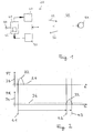
- the in FIG. 1 illustrated generic optoelectronic sensor 10 for measuring a distance d of objects 50 has as essential components a transmitting unit 20 for emitting light pulses 22 in a detection area 60, a receiving unit 30 for detecting light pulses 32 from a to be measured Object 50 are reflected back in the detection area 60, and a control and evaluation unit 40 on.
- the control and evaluation unit 40 is used to control the transmitting unit 20 and to evaluate the reflected light pulses 32 detected by the receiving unit 30 and is also adapted to a time difference between a reception time t2 of a light pulse 32 reflected back from the object 50 and a transmission time t1 this Light pulse 22 to determine a distance d of the object 50 to be measured.
- This basic measurement principle is related to FIG. 2 described in more detail.
- the transmission power PT (vertical axis 24) of a light source of the transmitting unit 20, typically a laser diode, is plotted against time t.
- the diagram below shows the received power PR (vertical axis 34) measured in the receiving unit 30 by a receiver, typically a photodiode, as a function of the time t.
- a measurement begins with the emission of a light pulse 22, which in FIG. 2 is reproduced by a pulse-like course of the transmission power PT.
- the time t1 is selected on the rising edge of the pulse 22 at which the edge pierces a selected threshold 26.
- This can be implemented electronically, for example, by interrogating a current with which a laser diode is driven. Because the current through a laser diode usually has a comparatively defined and reproducible profile, the starting point for the time measurement is comparatively well defined.
- Challenging is the situation when measuring the received pulse, essentially because the light pulses are reflected in the practical measuring operation of optically very different objects and beyond a variety of interfaces, such as a windscreen of the sensor, go through.
- the light pulses are therefore subjected in the course of their path from the transmitter via the object to the receiver of a variety of not exactly defined influences and are changed by this in the pulse height and the pulse width.
- the in FIG. 2 shown in the lower diagram not only a reception time, but it is first determined that time t2 at which a rising edge of the received pulse 32 pierces a selected threshold 36 and also the time t3 is measured at which the falling edge of the received pulse 32 the Threshold 36 pierces. It is immediately apparent that with higher and wider pulses the time t2 in the diagram of the FIG. 2 to the left and the time t3 accordingly moves to the right. By providing these two times by the measurement one obtains information about the pulse width which can be used for a correction of the time measurement.
- the time measurement as such ie the measurement of the time between the times t2 and t1 or the times t3 and t1, takes place using basically known means.
- a first essential approach of the present invention can be seen in that only the comparatively much better defined rising edge of the received pulse is used to determine the reception time of a light pulse. Based on the further essential finding that the measurement of a single time alone can not provide sufficient information about the reception time of the light pulse, the essential idea of the present invention is to instead of light pulses having only one pulse height or one pulse energy, to use light pulses having at least two different pulse heights or pulse energies.
- FIG. 3 shows a first (stronger) receive pulse 321 and a second (weaker) receive pulse 322.
- the first receive pulse 321 and the second receive pulse 322 are concurrent in the sense that their maxima in this schematic representation of FIG. 3 coincide. In practice, that will probably be the same way. It does not matter because the position of the maxima is not measured.
- the rising edge of the stronger first receive pulse 321 penetrates the threshold 36 at an earlier time t21 than the weaker second receive pulse 322, which pierces the threshold 36 only thereafter at a time designated by t22.
- the present invention has recognized that information about the steepness of the rising edge of, for example, the stronger first receive pulse 321 is included in the different times t21 and t22. This becomes clear, if one realizes that when using the same second received pulse 322, the difference between the times t22 and t21 becomes greater, the steeper the edge of the first receiving pulse 321 is.
- a first measurement of the pulse transit time is performed with a light pulse 321 with high pulse energy and a second measurement of the pulse transit time with a light pulse 322 with comparatively weak pulse energy.
- a measure of the pulse energy then the delay difference between the two measurements is used.
- This method has similarities to a measurement in which the rise time of the received pulses is measured using two different comparator thresholds.
- the use of light pulses 321, 322 having different height and a single threshold 36 is equivalent to use only one type of light pulses 321, but two different thresholds 361, 362.
- FIG. 4 shows.
- the pulse 321 penetrates the lower threshold 361 (which in the example shown should be the same as the threshold 36) FIG. 3 ) at time t21 and the higher threshold 362 at time t22.
- the higher threshold 362 is chosen so that the time t22 of FIG. 4 is identical to the time t22 of FIG. 3 ,
- the rise time can not be determined with the required resolution and accuracy with two comparator thresholds.
- the reasons for this are that the bandwidth of the receiver used limits the shortest possible rise time, so that high pulse energies are no longer distinguishable.
- the limited time resolution of the available time-to-digital converter (TDC) counteracts a measurement with the desired accuracy.
- the available receivers do not have the necessary dynamics.
- information about the steepness of the rising edge is, within certain limits, equivalent to information about a pulse width of the received light pulses.
- the steeper the rising edge of the light pulse the greater its pulse energy.
- the delta amplitude thus the difference of the measured reception times, can thus be used to correct the transit times.
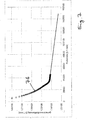
- FIG. 6 shows two experimentally recorded calibration curves 71, 72.
- the respective measured distance values for the light pulses with high pulse energy (calibration curve 71) or light pulses with low pulse energy (calibration curve 72) are plotted against the difference ⁇ of these distance values.
- the vertical axis is therefore equivalent to a time axis.
- the data in FIG. 6 were obtained with a measurement setup in which a reflective target was positioned as a test object at a constant distance relative to the optoelectronic sensor and the reflectivity of the target was varied defined.
- the reflectivity of the test object continuously increases from left to right.
- the received light pulses both the comparatively strong light pulses, calibration curve 71, and the comparatively weak light pulses, calibration curve 72 in the diagram in FIG. 6 stronger from left to right. This means that the rising edges of the received light pulses each become steeper and pierce the selected threshold accordingly earlier.
- the actual measuring points of the calibration curve 71 for the comparatively strong light pulses are FIG. 6 with triangles and those of the calibration curve 2 for the comparatively weak light pulses are shown with squares. The curves between these measuring points were interpolated.
- FIG. 6 An actual distance of the test object is in FIG. 6 represented by a horizontal line k0. This actual distance is of course independent of the reflectivity of the test object. It is clear, however, that the straight line k0 is in turn fixed only to an additive constant. For the actual exact distance, it depends on where, based on the optoelectronic sensor, the zero point of the distance measurement is determined.
- a measured difference ⁇ uniquely a time delay correction or, what is equivalent, a distance correction k ( ⁇ ) can be assigned.
- This distance correction k ( ⁇ ) can, as in FIG. 6 exemplified, are related to the calibration curve 71 for the comparatively strong light pulses. However, it is equivalent if the difference between the straight line k0 and the calibration curve 72 is used for the distance correction. A distance correction thus obtained would then have to be applied to the measured values obtained for the weak light pulses. Because k0, as discussed, is fixed only to an additive constant, the distance correction k ( ⁇ ) is fixed only to an additive constant.
- FIG. 7 a calibration curve 76 of the prior art. Plotted there is a measured distance (vertical axis) against the measured pulse width. The pulse width was determined, as explained above, by measuring the times at which the rising edge of a received light pulse and the falling edge of this light pulse pierce a threshold. Because of the overdriving of the receivers with very intense pulses stand out in the diagram FIG. 7 Measured values available only up to a pulse width of about 46000 * 0.1mm. Because, deviating from the situation of the calibration curves 71, 72 for the inventive method in FIG.
- the invention accomplishes here, as related to FIG. 6 explains, considerable improvements, because the higher in the method according to the invention (delta amplitude compensation) is the pulse energy of the received light pulses, the lower the measured delta amplitude, which can also be referred to as delta distance difference. This has the consequence that the uncertainty for the extrapolated amplitudes can be at most as large as half the delta distance difference. In FIG. 6 this value is 10 mm. By a simple linear extrapolation, this error is much lower in practice and in particular may be less than 1 mm.
- FIG. 5 shows a schematic representation of an optoelectronic sensor 100 according to the invention.
- the optoelectronic sensor 100 according to the invention has a structurally similar structure to a sensor from the prior art. Differences exist in the area of the control and evaluation unit 40. According to the invention, this is set up to drive the transmitting unit 20 to emit light pulses 221, 222 with at least two different pulse energies and depending on a difference of the received times t221, t222 of the received pulses measured for the different pulse energies Light pulses 321, 322 to correct the reception time with a correction value k ( ⁇ ).
- the control and evaluation unit 40 expediently has a memory 42 for storing the calibration information in the manner of the calibration curves 71, 72.
- the optoelectronic sensor 100 may have an interface 44, for example a bus interface.
- the present invention provides a novel method for determining a distance of objects using optoelectronic sensors according to the transit time method.
- This method is characterized by particularly versatile uses, a particularly high dynamic range of usable light pulses and by a particularly high accuracy, especially for very strong light pulses.
- the invention solves the problem in that it is measured with successive light pulses with different amplitude.
- the terms amplitude, pulse energy and pulse height are used here essentially synonymously.
- a time measurement is started, which is terminated, for example, by the exceeding of a specified threshold by the echo signal.
- the echo signal is here the one receiving signal referred to, which is triggered by a light reflected back from an object light pulse.
- a transit time measurement is carried out, which is subject to an amplitude error.
- the evaluation unit can be designed so that it can determine the time difference between two successive individual measurements with different transmission amplitudes.
- the invention is based on the finding that information about the amplitude of the echo signals is contained in the time difference of successive measurements with different amplitude.
- a memory device can be provided in which at least one empirically obtained correction table or curve can be contained.
- This correction table or curve may include correction values obtained for at least one constant calibration distance, each with calibration measurements taken at different calibration amplitudes.
- the correction table can in principle be taken for each measured time difference of successive individual measurements with different pulse energies of the light pulses, a corresponding correction value.
- a measurement whose measurement result is corrected for the amplitude error consists of at least two consecutive individual measurements, in which in particular a first measurement with a low transmission amplitude and a second measurement with a higher transmission amplitude is performed.
- the correction is based on the time difference between the two individual measurements based on the empirically determined correction table or curve.
Landscapes
- Engineering & Computer Science (AREA)
- Physics & Mathematics (AREA)
- Computer Networks & Wireless Communication (AREA)
- General Physics & Mathematics (AREA)
- Radar, Positioning & Navigation (AREA)
- Remote Sensing (AREA)
- Electromagnetism (AREA)
- Optical Radar Systems And Details Thereof (AREA)
Applications Claiming Priority (1)
| Application Number | Priority Date | Filing Date | Title |
|---|---|---|---|
| DE102018111217.3A DE102018111217A1 (de) | 2018-05-09 | 2018-05-09 | Verfahren und optoelektronischer Sensor zum Messen einer Entfernung von Objekten |
Publications (2)
| Publication Number | Publication Date |
|---|---|
| EP3567397A1 true EP3567397A1 (fr) | 2019-11-13 |
| EP3567397B1 EP3567397B1 (fr) | 2022-07-06 |
Family
ID=66429273
Family Applications (1)
| Application Number | Title | Priority Date | Filing Date |
|---|---|---|---|
| EP19172782.5A Active EP3567397B1 (fr) | 2018-05-09 | 2019-05-06 | Procédé et capteur optoélectronique permettant de mesurer l'éloignement d'objets |
Country Status (2)
| Country | Link |
|---|---|
| EP (1) | EP3567397B1 (fr) |
| DE (1) | DE102018111217A1 (fr) |
Cited By (3)
| Publication number | Priority date | Publication date | Assignee | Title |
|---|---|---|---|---|
| CN114325738A (zh) * | 2021-12-23 | 2022-04-12 | 探维科技(北京)有限公司 | 测量距离的方法及激光雷达 |
| CN114442106A (zh) * | 2022-01-28 | 2022-05-06 | 西安知微传感技术有限公司 | 激光雷达系统的校准方法及装置 |
| WO2023137054A1 (fr) * | 2022-01-12 | 2023-07-20 | Luminar, Llc | Système lidar avec détermination d'angle d'incidence |
Families Citing this family (1)
| Publication number | Priority date | Publication date | Assignee | Title |
|---|---|---|---|---|
| CN119439178B (zh) * | 2023-08-03 | 2026-01-06 | 深圳市速腾聚创科技有限公司 | 雷达测距方法、装置、电子设备和计算机可读存储介质 |
Citations (4)
| Publication number | Priority date | Publication date | Assignee | Title |
|---|---|---|---|---|
| JPH08105971A (ja) * | 1994-10-05 | 1996-04-23 | Hitachi Ltd | マルチパルスによる測距方法とその装置 |
| EP0782007A2 (fr) | 1995-12-27 | 1997-07-02 | Denso Corporation | Système et dispositif pour mesurer la distance |
| WO2009156580A1 (fr) * | 2008-06-27 | 2009-12-30 | Oulun Yliopisto | Procédé et dispositif pour mesurer une distance |
| WO2010051615A1 (fr) * | 2008-11-05 | 2010-05-14 | Neptec Design Group Ltd. | Analyse de la forme d’une impulsion de retour pour la discrimination par fronts descendants d’objets dans un aérosol lidar |
-
2018
- 2018-05-09 DE DE102018111217.3A patent/DE102018111217A1/de not_active Withdrawn
-
2019
- 2019-05-06 EP EP19172782.5A patent/EP3567397B1/fr active Active
Patent Citations (4)
| Publication number | Priority date | Publication date | Assignee | Title |
|---|---|---|---|---|
| JPH08105971A (ja) * | 1994-10-05 | 1996-04-23 | Hitachi Ltd | マルチパルスによる測距方法とその装置 |
| EP0782007A2 (fr) | 1995-12-27 | 1997-07-02 | Denso Corporation | Système et dispositif pour mesurer la distance |
| WO2009156580A1 (fr) * | 2008-06-27 | 2009-12-30 | Oulun Yliopisto | Procédé et dispositif pour mesurer une distance |
| WO2010051615A1 (fr) * | 2008-11-05 | 2010-05-14 | Neptec Design Group Ltd. | Analyse de la forme d’une impulsion de retour pour la discrimination par fronts descendants d’objets dans un aérosol lidar |
Non-Patent Citations (1)
| Title |
|---|
| G. ZHOU ET AL: "IMPROVEMENT ON TIMING ACCURACY OF LIDAR FOR REMOTE SENSING", ISPRS - INTERNATIONAL ARCHIVES OF THE PHOTOGRAMMETRY, REMOTE SENSING AND SPATIAL INFORMATION SCIENCES, vol. XLII-3, 2 May 2018 (2018-05-02), pages 2495 - 2498, XP055624496, DOI: 10.5194/isprs-archives-XLII-3-2495-2018 * |
Cited By (4)
| Publication number | Priority date | Publication date | Assignee | Title |
|---|---|---|---|---|
| CN114325738A (zh) * | 2021-12-23 | 2022-04-12 | 探维科技(北京)有限公司 | 测量距离的方法及激光雷达 |
| CN114325738B (zh) * | 2021-12-23 | 2023-01-10 | 探维科技(北京)有限公司 | 测量距离的方法及激光雷达 |
| WO2023137054A1 (fr) * | 2022-01-12 | 2023-07-20 | Luminar, Llc | Système lidar avec détermination d'angle d'incidence |
| CN114442106A (zh) * | 2022-01-28 | 2022-05-06 | 西安知微传感技术有限公司 | 激光雷达系统的校准方法及装置 |
Also Published As
| Publication number | Publication date |
|---|---|
| DE102018111217A1 (de) | 2019-11-14 |
| EP3567397B1 (fr) | 2022-07-06 |
Similar Documents
| Publication | Publication Date | Title |
|---|---|---|
| EP3567397B1 (fr) | Procédé et capteur optoélectronique permettant de mesurer l'éloignement d'objets | |
| EP2558883B1 (fr) | Appareil de mesure de distance à évaluation de mesure à effet homogénéisant | |
| EP2041604B1 (fr) | Procédé de mesure de distance optique et télémètre optique correspondant | |
| DE102007021614B4 (de) | Radarvorrichtung | |
| EP1876469B1 (fr) | Procédé et dispositif destinés à la mesure de distance optoélectronique sans contact selon le principe de durée | |
| DE102007013714A1 (de) | Optoelektronischer Sensor und Verfahren zur Messung einer Entfernung oder einer Entfernungsänderung | |
| EP0793115A2 (fr) | Radar à laser à résolution millimétrique | |
| DE102007030978A1 (de) | Radarvorrichtung | |
| EP3232224B1 (fr) | Capteur telemetrique optoelectronique et procede de detection et de determination de distances entre des objets | |
| EP3809157A1 (fr) | Capteur optoélectronique de mesure de distance et procédé de détection d'un objet cible | |
| WO2011042290A1 (fr) | Télémètre optique avec dispositif d'étalonnage | |
| EP2395368A1 (fr) | Scanner laser mesurant l'éloignement destiné à la détection d'objets dans une zone de surveillance | |
| EP0742450A2 (fr) | Procédé et dispositif de mesure du temps de vol de lumière le long d'une trajectoire de mesure entre un dispositif de mesure et un objet réfléchissant | |
| DE102015217912A1 (de) | Verfahren zur Laufzeitkalibrierung eines Lidarsensors | |
| WO2020043244A1 (fr) | Procédé de détection d'une dégradation d'un système de mesure de distance | |
| EP3567398B1 (fr) | Procédé et capteur optoélectronique permettant de mesurer l'éloignement d'objets | |
| WO2008003481A1 (fr) | Procédé et dispositif demesure d'une distance de manière optoélectronique sans contact | |
| EP2962127B1 (fr) | Procédé de détermination d'une distance d'un objet par rapport à un véhicule à moteur en utilisant un capteur pmd | |
| DE102004031024B4 (de) | Optischer Sensor | |
| EP3229042B1 (fr) | Capteur optoélectronique et procédé de détection et de détermination de distance par rapport à un objet | |
| EP4241111A1 (fr) | Procédé de détermination d'un changement de portée d'un capteur lidar | |
| DE102012108462A1 (de) | Verfahren, Vorrichtung und System zur Laserbasierten Bestimmung des Füllstands eines Füllguts in einem Behälter | |
| DE102007011417A1 (de) | Vorrichtung und Verfahren zur Entfernungsbestimmung | |
| AT508344B1 (de) | Verfahren zur aufnahme eines objektraumes | |
| EP4102249B1 (fr) | Méthode et capteur optique pour mesurer une distance d'un objet |
Legal Events
| Date | Code | Title | Description |
|---|---|---|---|
| PUAI | Public reference made under article 153(3) epc to a published international application that has entered the european phase |
Free format text: ORIGINAL CODE: 0009012 |
|
| STAA | Information on the status of an ep patent application or granted ep patent |
Free format text: STATUS: THE APPLICATION HAS BEEN PUBLISHED |
|
| AK | Designated contracting states |
Kind code of ref document: A1 Designated state(s): AL AT BE BG CH CY CZ DE DK EE ES FI FR GB GR HR HU IE IS IT LI LT LU LV MC MK MT NL NO PL PT RO RS SE SI SK SM TR |
|
| AX | Request for extension of the european patent |
Extension state: BA ME |
|
| STAA | Information on the status of an ep patent application or granted ep patent |
Free format text: STATUS: REQUEST FOR EXAMINATION WAS MADE |
|
| 17P | Request for examination filed |
Effective date: 20200513 |
|
| RBV | Designated contracting states (corrected) |
Designated state(s): AL AT BE BG CH CY CZ DE DK EE ES FI FR GB GR HR HU IE IS IT LI LT LU LV MC MK MT NL NO PL PT RO RS SE SI SK SM TR |
|
| GRAP | Despatch of communication of intention to grant a patent |
Free format text: ORIGINAL CODE: EPIDOSNIGR1 |
|
| STAA | Information on the status of an ep patent application or granted ep patent |
Free format text: STATUS: GRANT OF PATENT IS INTENDED |
|
| INTG | Intention to grant announced |
Effective date: 20211117 |
|
| GRAS | Grant fee paid |
Free format text: ORIGINAL CODE: EPIDOSNIGR3 |
|
| RAP3 | Party data changed (applicant data changed or rights of an application transferred) |
Owner name: PEPPERL+FUCHS SE |
|
| GRAA | (expected) grant |
Free format text: ORIGINAL CODE: 0009210 |
|
| STAA | Information on the status of an ep patent application or granted ep patent |
Free format text: STATUS: THE PATENT HAS BEEN GRANTED |
|
| AK | Designated contracting states |
Kind code of ref document: B1 Designated state(s): AL AT BE BG CH CY CZ DE DK EE ES FI FR GB GR HR HU IE IS IT LI LT LU LV MC MK MT NL NO PL PT RO RS SE SI SK SM TR |
|
| REG | Reference to a national code |
Ref country code: AT Ref legal event code: REF Ref document number: 1503237 Country of ref document: AT Kind code of ref document: T Effective date: 20220715 Ref country code: CH Ref legal event code: EP |
|
| REG | Reference to a national code |
Ref country code: DE Ref legal event code: R096 Ref document number: 502019004850 Country of ref document: DE |
|
| REG | Reference to a national code |
Ref country code: IE Ref legal event code: FG4D Free format text: LANGUAGE OF EP DOCUMENT: GERMAN |
|
| REG | Reference to a national code |
Ref country code: LT Ref legal event code: MG9D |
|
| REG | Reference to a national code |
Ref country code: NL Ref legal event code: MP Effective date: 20220706 |
|
| PG25 | Lapsed in a contracting state [announced via postgrant information from national office to epo] |
Ref country code: SE Free format text: LAPSE BECAUSE OF FAILURE TO SUBMIT A TRANSLATION OF THE DESCRIPTION OR TO PAY THE FEE WITHIN THE PRESCRIBED TIME-LIMIT Effective date: 20220706 Ref country code: RS Free format text: LAPSE BECAUSE OF FAILURE TO SUBMIT A TRANSLATION OF THE DESCRIPTION OR TO PAY THE FEE WITHIN THE PRESCRIBED TIME-LIMIT Effective date: 20220706 Ref country code: PT Free format text: LAPSE BECAUSE OF FAILURE TO SUBMIT A TRANSLATION OF THE DESCRIPTION OR TO PAY THE FEE WITHIN THE PRESCRIBED TIME-LIMIT Effective date: 20221107 Ref country code: NO Free format text: LAPSE BECAUSE OF FAILURE TO SUBMIT A TRANSLATION OF THE DESCRIPTION OR TO PAY THE FEE WITHIN THE PRESCRIBED TIME-LIMIT Effective date: 20221006 Ref country code: NL Free format text: LAPSE BECAUSE OF FAILURE TO SUBMIT A TRANSLATION OF THE DESCRIPTION OR TO PAY THE FEE WITHIN THE PRESCRIBED TIME-LIMIT Effective date: 20220706 Ref country code: LV Free format text: LAPSE BECAUSE OF FAILURE TO SUBMIT A TRANSLATION OF THE DESCRIPTION OR TO PAY THE FEE WITHIN THE PRESCRIBED TIME-LIMIT Effective date: 20220706 Ref country code: LT Free format text: LAPSE BECAUSE OF FAILURE TO SUBMIT A TRANSLATION OF THE DESCRIPTION OR TO PAY THE FEE WITHIN THE PRESCRIBED TIME-LIMIT Effective date: 20220706 Ref country code: FI Free format text: LAPSE BECAUSE OF FAILURE TO SUBMIT A TRANSLATION OF THE DESCRIPTION OR TO PAY THE FEE WITHIN THE PRESCRIBED TIME-LIMIT Effective date: 20220706 Ref country code: ES Free format text: LAPSE BECAUSE OF FAILURE TO SUBMIT A TRANSLATION OF THE DESCRIPTION OR TO PAY THE FEE WITHIN THE PRESCRIBED TIME-LIMIT Effective date: 20220706 |
|
| PG25 | Lapsed in a contracting state [announced via postgrant information from national office to epo] |
Ref country code: PL Free format text: LAPSE BECAUSE OF FAILURE TO SUBMIT A TRANSLATION OF THE DESCRIPTION OR TO PAY THE FEE WITHIN THE PRESCRIBED TIME-LIMIT Effective date: 20220706 Ref country code: IS Free format text: LAPSE BECAUSE OF FAILURE TO SUBMIT A TRANSLATION OF THE DESCRIPTION OR TO PAY THE FEE WITHIN THE PRESCRIBED TIME-LIMIT Effective date: 20221106 Ref country code: HR Free format text: LAPSE BECAUSE OF FAILURE TO SUBMIT A TRANSLATION OF THE DESCRIPTION OR TO PAY THE FEE WITHIN THE PRESCRIBED TIME-LIMIT Effective date: 20220706 Ref country code: GR Free format text: LAPSE BECAUSE OF FAILURE TO SUBMIT A TRANSLATION OF THE DESCRIPTION OR TO PAY THE FEE WITHIN THE PRESCRIBED TIME-LIMIT Effective date: 20221007 |
|
| REG | Reference to a national code |
Ref country code: DE Ref legal event code: R097 Ref document number: 502019004850 Country of ref document: DE |
|
| PG25 | Lapsed in a contracting state [announced via postgrant information from national office to epo] |
Ref country code: SM Free format text: LAPSE BECAUSE OF FAILURE TO SUBMIT A TRANSLATION OF THE DESCRIPTION OR TO PAY THE FEE WITHIN THE PRESCRIBED TIME-LIMIT Effective date: 20220706 Ref country code: RO Free format text: LAPSE BECAUSE OF FAILURE TO SUBMIT A TRANSLATION OF THE DESCRIPTION OR TO PAY THE FEE WITHIN THE PRESCRIBED TIME-LIMIT Effective date: 20220706 Ref country code: DK Free format text: LAPSE BECAUSE OF FAILURE TO SUBMIT A TRANSLATION OF THE DESCRIPTION OR TO PAY THE FEE WITHIN THE PRESCRIBED TIME-LIMIT Effective date: 20220706 Ref country code: CZ Free format text: LAPSE BECAUSE OF FAILURE TO SUBMIT A TRANSLATION OF THE DESCRIPTION OR TO PAY THE FEE WITHIN THE PRESCRIBED TIME-LIMIT Effective date: 20220706 |
|
| PLBE | No opposition filed within time limit |
Free format text: ORIGINAL CODE: 0009261 |
|
| STAA | Information on the status of an ep patent application or granted ep patent |
Free format text: STATUS: NO OPPOSITION FILED WITHIN TIME LIMIT |
|
| PG25 | Lapsed in a contracting state [announced via postgrant information from national office to epo] |
Ref country code: SK Free format text: LAPSE BECAUSE OF FAILURE TO SUBMIT A TRANSLATION OF THE DESCRIPTION OR TO PAY THE FEE WITHIN THE PRESCRIBED TIME-LIMIT Effective date: 20220706 Ref country code: EE Free format text: LAPSE BECAUSE OF FAILURE TO SUBMIT A TRANSLATION OF THE DESCRIPTION OR TO PAY THE FEE WITHIN THE PRESCRIBED TIME-LIMIT Effective date: 20220706 |
|
| 26N | No opposition filed |
Effective date: 20230411 |
|
| PG25 | Lapsed in a contracting state [announced via postgrant information from national office to epo] |
Ref country code: AL Free format text: LAPSE BECAUSE OF FAILURE TO SUBMIT A TRANSLATION OF THE DESCRIPTION OR TO PAY THE FEE WITHIN THE PRESCRIBED TIME-LIMIT Effective date: 20220706 |
|
| PG25 | Lapsed in a contracting state [announced via postgrant information from national office to epo] |
Ref country code: SI Free format text: LAPSE BECAUSE OF FAILURE TO SUBMIT A TRANSLATION OF THE DESCRIPTION OR TO PAY THE FEE WITHIN THE PRESCRIBED TIME-LIMIT Effective date: 20220706 |
|
| PG25 | Lapsed in a contracting state [announced via postgrant information from national office to epo] |
Ref country code: MC Free format text: LAPSE BECAUSE OF FAILURE TO SUBMIT A TRANSLATION OF THE DESCRIPTION OR TO PAY THE FEE WITHIN THE PRESCRIBED TIME-LIMIT Effective date: 20220706 |
|
| GBPC | Gb: european patent ceased through non-payment of renewal fee |
Effective date: 20230506 |
|
| REG | Reference to a national code |
Ref country code: BE Ref legal event code: MM Effective date: 20230531 |
|
| PG25 | Lapsed in a contracting state [announced via postgrant information from national office to epo] |
Ref country code: MC Free format text: LAPSE BECAUSE OF FAILURE TO SUBMIT A TRANSLATION OF THE DESCRIPTION OR TO PAY THE FEE WITHIN THE PRESCRIBED TIME-LIMIT Effective date: 20220706 Ref country code: LU Free format text: LAPSE BECAUSE OF NON-PAYMENT OF DUE FEES Effective date: 20230506 Ref country code: IT Free format text: LAPSE BECAUSE OF FAILURE TO SUBMIT A TRANSLATION OF THE DESCRIPTION OR TO PAY THE FEE WITHIN THE PRESCRIBED TIME-LIMIT Effective date: 20220706 |
|
| REG | Reference to a national code |
Ref country code: IE Ref legal event code: MM4A |
|
| PG25 | Lapsed in a contracting state [announced via postgrant information from national office to epo] |
Ref country code: IE Free format text: LAPSE BECAUSE OF NON-PAYMENT OF DUE FEES Effective date: 20230506 |
|
| PG25 | Lapsed in a contracting state [announced via postgrant information from national office to epo] |
Ref country code: IE Free format text: LAPSE BECAUSE OF NON-PAYMENT OF DUE FEES Effective date: 20230506 Ref country code: GB Free format text: LAPSE BECAUSE OF NON-PAYMENT OF DUE FEES Effective date: 20230506 |
|
| PG25 | Lapsed in a contracting state [announced via postgrant information from national office to epo] |
Ref country code: BE Free format text: LAPSE BECAUSE OF NON-PAYMENT OF DUE FEES Effective date: 20230531 |
|
| PG25 | Lapsed in a contracting state [announced via postgrant information from national office to epo] |
Ref country code: BG Free format text: LAPSE BECAUSE OF FAILURE TO SUBMIT A TRANSLATION OF THE DESCRIPTION OR TO PAY THE FEE WITHIN THE PRESCRIBED TIME-LIMIT Effective date: 20220706 |
|
| PG25 | Lapsed in a contracting state [announced via postgrant information from national office to epo] |
Ref country code: BG Free format text: LAPSE BECAUSE OF FAILURE TO SUBMIT A TRANSLATION OF THE DESCRIPTION OR TO PAY THE FEE WITHIN THE PRESCRIBED TIME-LIMIT Effective date: 20220706 |
|
| PGFP | Annual fee paid to national office [announced via postgrant information from national office to epo] |
Ref country code: DE Payment date: 20250519 Year of fee payment: 7 |
|
| PGFP | Annual fee paid to national office [announced via postgrant information from national office to epo] |
Ref country code: FR Payment date: 20250523 Year of fee payment: 7 |
|
| PGFP | Annual fee paid to national office [announced via postgrant information from national office to epo] |
Ref country code: CH Payment date: 20250601 Year of fee payment: 7 |
|
| PGFP | Annual fee paid to national office [announced via postgrant information from national office to epo] |
Ref country code: AT Payment date: 20250519 Year of fee payment: 7 |
|
| PG25 | Lapsed in a contracting state [announced via postgrant information from national office to epo] |
Ref country code: CY Free format text: LAPSE BECAUSE OF FAILURE TO SUBMIT A TRANSLATION OF THE DESCRIPTION OR TO PAY THE FEE WITHIN THE PRESCRIBED TIME-LIMIT; INVALID AB INITIO Effective date: 20190506 |
|
| PG25 | Lapsed in a contracting state [announced via postgrant information from national office to epo] |
Ref country code: HU Free format text: LAPSE BECAUSE OF FAILURE TO SUBMIT A TRANSLATION OF THE DESCRIPTION OR TO PAY THE FEE WITHIN THE PRESCRIBED TIME-LIMIT; INVALID AB INITIO Effective date: 20190506 |
|
| PG25 | Lapsed in a contracting state [announced via postgrant information from national office to epo] |
Ref country code: TR Free format text: LAPSE BECAUSE OF FAILURE TO SUBMIT A TRANSLATION OF THE DESCRIPTION OR TO PAY THE FEE WITHIN THE PRESCRIBED TIME-LIMIT Effective date: 20220706 |