EP3567953A1 - Benutzerendgerät und drahtloskommunikationsverfahren - Google Patents
Benutzerendgerät und drahtloskommunikationsverfahren Download PDFInfo
- Publication number
- EP3567953A1 EP3567953A1 EP18736655.4A EP18736655A EP3567953A1 EP 3567953 A1 EP3567953 A1 EP 3567953A1 EP 18736655 A EP18736655 A EP 18736655A EP 3567953 A1 EP3567953 A1 EP 3567953A1
- Authority
- EP
- European Patent Office
- Prior art keywords
- dci
- candidates
- downlink control
- symbols
- control channel
- Prior art date
- Legal status (The legal status is an assumption and is not a legal conclusion. Google has not performed a legal analysis and makes no representation as to the accuracy of the status listed.)
- Withdrawn
Links
Images







Classifications
-
- H—ELECTRICITY
- H04—ELECTRIC COMMUNICATION TECHNIQUE
- H04W—WIRELESS COMMUNICATION NETWORKS
- H04W72/00—Local resource management
- H04W72/20—Control channels or signalling for resource management
- H04W72/23—Control channels or signalling for resource management in the downlink direction of a wireless link, i.e. towards a terminal
-
- H—ELECTRICITY
- H04—ELECTRIC COMMUNICATION TECHNIQUE
- H04L—TRANSMISSION OF DIGITAL INFORMATION, e.g. TELEGRAPHIC COMMUNICATION
- H04L27/00—Modulated-carrier systems
- H04L27/26—Systems using multi-frequency codes
-
- H—ELECTRICITY
- H04—ELECTRIC COMMUNICATION TECHNIQUE
- H04L—TRANSMISSION OF DIGITAL INFORMATION, e.g. TELEGRAPHIC COMMUNICATION
- H04L5/00—Arrangements affording multiple use of the transmission path
- H04L5/003—Arrangements for allocating sub-channels of the transmission path
- H04L5/0053—Allocation of signalling, i.e. of overhead other than pilot signals
-
- H—ELECTRICITY
- H04—ELECTRIC COMMUNICATION TECHNIQUE
- H04W—WIRELESS COMMUNICATION NETWORKS
- H04W72/00—Local resource management
- H04W72/04—Wireless resource allocation
-
- H—ELECTRICITY
- H04—ELECTRIC COMMUNICATION TECHNIQUE
- H04L—TRANSMISSION OF DIGITAL INFORMATION, e.g. TELEGRAPHIC COMMUNICATION
- H04L5/00—Arrangements affording multiple use of the transmission path
- H04L5/0001—Arrangements for dividing the transmission path
- H04L5/0003—Two-dimensional division
- H04L5/0005—Time-frequency
-
- H—ELECTRICITY
- H04—ELECTRIC COMMUNICATION TECHNIQUE
- H04L—TRANSMISSION OF DIGITAL INFORMATION, e.g. TELEGRAPHIC COMMUNICATION
- H04L5/00—Arrangements affording multiple use of the transmission path
- H04L5/0001—Arrangements for dividing the transmission path
- H04L5/0003—Two-dimensional division
- H04L5/0005—Time-frequency
- H04L5/0007—Time-frequency the frequencies being orthogonal, e.g. OFDM(A) or DMT
Definitions
- the present invention relates to a user terminal and a radio communication method in next-generation mobile communication systems.
- LTE Long term evolution
- LTE-A also referred to as “LTE-advanced,” “LTE Rel. 10,” “LTE Rel. 11,” or “LTE Rel. 12”
- LTE Rel. 8 Long Term Evolution
- LTE Long Term Evolution
- 5G Fifth Generation mobile communication system
- 5G+ plus
- NR New Radio
- NX New radio access
- New RAT Radio Access Technology
- FX Full Generation radio access
- CA carrier aggregation
- CC component carriers
- eNB evolved Node B
- BS Base Station
- UE User Equipment
- DC dual connectivity
- CGs cell groups
- CC cell
- inter-eNB CA inter-eNB CA
- FDD frequency division duplex
- TDD time division duplex
- Non-Patent Literature 1 3GPP TS36.300 V8.12.0 "Evolved Universal Terrestrial Radio Access (E-UTRA) and Evolved Universal Terrestrial Radio Access Network (E-UTRAN); Overall description; Stage 2 (Release 8)," April, 2010
- Future radio communication systems for example, 5G, NR, etc. are expected to realize various radio communication services so as to fulfill varying requirements (for example, ultra high speed, large capacity, ultra-low latency, etc.).
- 5G/NR studies are in progress to provide radio communication services, referred to as "eMBB (enhanced Mobile Broad Band),” "loT (Internet of Things),” “mMTC (massive Machine Type Communication),” “M2M (Machine To Machine),” and “URLLC (Ultra Reliable and Low Latency Communications).”
- 5G/NR is expected to support flexible use of numerologies and frequencies, and realize a dynamic frame formats.
- a "numerology" refers to, for example, a set of communication parameters (for example, subcarrier spacing, bandwidth, etc.) applied to transmission and receipt of a certain signal.
- the present invention has been made in view of the above, and it is therefore an object of the present invention to provide a user terminal and a radio communication method to enable proper communication in a radio communication system that supports different numerologies than existing LTE systems.
- a user terminal has a receiving section that receives a downlink control channel, and a control section that controls detection of candidates for allocating the downlink control channel are provided, and, in this user terminal, when the downlink control channel is configured in a plurality of symbols, the control section controls the detection of downlink control channel allocation candidates that are arranged in one-symbol units and downlink control channel allocation candidates that are arranged over multiple symbols.
- a base station transmits downlink control information (DCI) to a UE using a downlink control channel (for example, PDCCH (Physical Downlink Control Channel), enhanced PDCCH (EPDCCH (Enhanced PDCCH), etc.).
- DCI downlink control information
- a downlink control channel for example, PDCCH (Physical Downlink Control Channel), enhanced PDCCH (EPDCCH (Enhanced PDCCH), etc.
- PDCCH Physical Downlink Control Channel
- EPDCCH Enhanced PDCCH
- DCI includes, for example, data-scheduling time/frequency resources, transport block information, data modulation scheme information, HARQ retransmission information, demodulation RS information, and so on.
- DCI that schedules receipt of DL data and/or measurement of DL reference signals may be referred to as "DL assignment” or "DL grant,” or DCI that schedules transmission of UL data and/or transmission of UL sounding (measurement) signals may be referred to as "UL grant.”
- DL assignments and/or UL grants may include information about the resources, sequence, transmission format and/or others of the channel for transmitting UL control signals (UCI: Uplink Control Information), such as HARQ-ACK feedback in response to DL data, channel measurement information (CSI: Channel State Information), and so on.
- UCI Uplink Control Information
- CSI Channel State Information
- the UE is configured to monitor a set of a predetermined number of downlink control channel candidates. Monitoring here means, for example, attempting to decode each downlink control channel for the target DCI format in the set. Such decoding is also referred to as “blind decoding (BD)” or “blind detection.” Downlink control channel candidates are also referred to as “candidates for allocating downlink control channels,” “BD candidates,” “(E)PDCCH candidates,” “DCI candidates,” and so on.
- BD blind decoding
- the set of downlink control channel candidates (multiple downlink control channel candidates) to be monitored is also referred to as "search space.”
- the base station places DCI in a predetermined downlink control channel candidates included in the search space.
- the UE performs blind decoding for one or more candidate resources in the search space, and detects the DCI addressed to the UE.
- the search space may be configured by high layer signaling that is common between users, or may be configured by user-specific high layer signaling.
- a plurality of aggregation levels are provided in the search space for the purpose of link adaptation.
- the ALs correspond to the numbers of control channel elements (CCEs)/enhanced control channel elements (ECCEs: Enhanced CCEs) that constitute DCI.
- the search space is configured so that there are multiple downlink control channel candidates for a given AL.
- Each downlink control channel candidate is comprised of one or more resource units (CCEs and/or ECCEs).
- Cyclic redundancy check (CRC) bits are attached to the DCI.
- the CRC is masked (scrambled) using UE-Specific identifiers (for example, cell-radio network temporary identifiers (C-RNTIs)) or a system-common identifier.
- C-RNTIs cell-radio network temporary identifiers
- the UE can detect the DCI where the CRC is scrambled using the C-RNTI for the subject terminal, and the DCI where the CRC is scrambled using the system-common identifier.
- the search spaces there are a common search space (C-SS) that is configured for UEs on a shared basis, and a UE-specific search space (UE-SS) that is configured for each UE.
- C-SS common search space
- UE-SS UE-specific search space
- the ALs the numbers of CCEs
- a numerology refers to a set of frequency-domain and/or time domain-communication parameters (for example, at least one of the subcarrier spacing (SCS), the bandwidth, the duration of symbols, the duration of cyclic prefixes (CPs), the duration of transmission time intervals (TTIs), the number of symbols per TTI, the format of radio frames, the filtering process, the windowing process and so on).
- SCS subcarrier spacing
- CPs duration of symbols
- TTIs transmission time intervals
- a downlink control channel is allocated (also referred to as a "control resource set")
- downlink control channel candidates blind decoding candidates
- a control resource set is constituted by a plurality of symbol periods (for example, three symbols)
- a user terminal has to wait until all three symbols are received and then perform blind decoding for the downlink control channel candidates.
- control resource set for allocating a downlink control channel may not be limited to being one symbol, and can be configured over multiple symbol periods (see FIG. 2).
- FIG. 2 illustrates a case where control resource sets are each constituted by one to three symbols.
- FIG. 3A illustrates a case where, in a transmission time interval, the receiving processes of DL signals (for example, data and/or downlink control information) are performed in this transmission time interval as the unit (referred to as "non-pipeline processing,” “non-pipeline processing structure,” and so on),
- the receiving processes performed here include the demodulation process, the decoding process and other processes.
- delivery acknowledgment signals in response to DL data also referred to as "HARQ-ACK,” “ACK/NACK,” and so on
- HARQ-ACK ACK/NACK
- FIG. 3B illustrates a case where the receiving processes of DL signals are performed in symbol units in a transmission time interval (pipeline processing, pipeline processing structure).
- the receiving processes are conducted in symbol units, so that, compared with FIG. 3A , the processing time required for the receiving operation can be shortened (for example, the receiving processes take one or several symbols).
- pipeline processing may be performed per symbol group (for example, every two symbols), not per symbol.
- the present inventors have come up with the idea of shortening the processing time by applying pipeline processing to the transmission of downlink control information (or downlink control channels). Also, assuming the case where pipeline processing is applied to the transmission of downlink control information, the present inventors have come up with the idea of using a method of arrangement that is different from the method of arranging downlink control channel candidates in existing LTE systems.
- a downlink control channel when a downlink control channel is configured in a plurality of predetermined time units (for example, a plurality of symbols), downlink control channel candidates that are arranged in one-symbol units and/or downlink control channel candidates that are arranged over a plurality of symbols are arranged.
- a user terminal can detect (receiving process) the downlink control channel candidates in order of symbols that are received.
- the search space in the following embodiments may be at least one of a common search space (C-SS), a UE specific search space, a UE group common search space, and/or other search spaces.
- C-SS common search space
- UE specific search space a UE specific search space
- UE group common search space a search space that can be applied to the present embodiment is not limited to this.
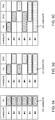
- FIGs. 4 illustrate examples of the method for mapping DCI candidates in the time domain.
- FIG. 4A illustrates a case in which the field to configure a downlink control channel is configured (for example, a control resource set) consists of one symbol (1st).
- FIGs. 4B and 4C illustrate cases in which the control resource sets consist of two symbols (1st and 2nd) and three symbols (1st to 3rd), respectively. That is, the second column, the second and third columns and the second to fourth columns in each table represent symbols of the field in which a downlink control channel is provided.
- the number of symbols to constitute a control resource set is not limited to three, and it is also possible to construct a control resource set using four or more symbols.
- DCI candidates can be mapped (allocated) at least on a symbol-by-symbol basis.
- the control resource set is comprised of one symbol
- a plurality of DCI candidates that are mapped in one-symbol units can be provided.
- DCI candidates #1 to #4 here DCI candidates that are mapped in one-symbol units
- DCI candidates #5 to #6 here DCI candidates that are mapped over two symbols
- DCI candidates #1 to #3 DCI candidates that are mapped in one-symbol units
- DCI candidates #4 to #5 DCI candidates that are mapped over two symbols
- DCI candidates that are mapped over three symbols can be configured.
- a radio base station can assign downlink control channels (downlink control information) to DCI candidates that are placed in the first half of the control resource set, thereby shortening the receiving operation of the user terminal.
- DCI downlink control information
- FIG. 5A when the control resource set is comprised of one symbol, DCI can be allocated to the DCI candidates that are formed in the first symbol (here, DCI candidates #1 to #6).
- FIG. 5B when the control resource set is comprised of two symbols, it is only necessary to selectively assign DCI to DCI candidates that are formed in the first symbol (here, DCI candidates #1 and #3).
- DCI may be assigned to DCI candidates formed in the first symbol and/or the second symbol (DCI candidates #1, #2, and #4, here).
- the user terminal When the user terminal detects DCI in one of the DCI candidates constituted by the first-half symbols of the control resource set, it is possible to proceed with the DL data receiving processes without waiting for the second-half DCI candidates to be decoded. By this means, even when the control resource set is constituted by a plurality of symbols, the delay of receiving processes in the user terminal can be reduced.
- the radio base station transmits DCI using DCI candidates that are mapped over a plurality of symbols ( FIGs. 6B and 6C ).
- the received signal energy when the transmission power is constant can be increased as compared with the case where the DCI candidates are each mapped in one symbol (DCI candidates #1 to #6 in FIG. 6A , DCI candidates #1 to #4 in FIG. 6B and DCI candidates #1 to #3 in FIG. 6C ).
- the radio base station can appropriately transmit the DCI (that is, the radio base station provides a better link budget or lowers the SINR required to achieve a predetermined error rate) by applying DCI candidates mapped over multiple symbols, to user terminals indicating high propagation loss such as cell-edge user terminals.
- the radio base station can assign DCI of different content to each symbol constituting that DCI candidate.
- the radio base station can appropriately combine pieces of information representing a reference signal (RS), a resource allocation (RA), a modulation and coding scheme (MCS), a PUCCH resource, a TPC command, a HARQ timing command, a DAI, an SRS trigger, a CSI trigger and so on, and assign combinations of these to different symbols.
- RS reference signal
- RA resource allocation
- MCS modulation and coding scheme
- FIGs. 7 where DCI candidates are mapped over two symbols (here, DCI candidates #5 and #6 in FIG. 7A and DCI candidates #4 and #5 in FIG. 7B ), one or a combination of an RS, an RA and an MCS is allocated to the first symbol in the time direction. Also, a case is illustrated here where one or a combination of a PUCCH resource, a TPC command, an HARQ timing command, a DAI, an SRS trigger and a CSI trigger is allocated to the second symbol.
- an RS is allocated to the first symbol in the time direction.
- an RA and/or an MCS are assigned to the second symbol.
- one or a combination of a PUCCH resource, a TPC command, an HARQ timing command, a DAI, an SRS trigger and a CSI trigger is allocated to the third symbol.
- an RS, an RA, an MCS and so on which are important and which are time-consuming in terms of receiving processes, are assigned to the first-half symbols among a plurality of symbols constituting DCI candidates, so that the user terminal can receive the RS, the RA, the MCS and so on earlier. This makes it possible to reserve time for receiving processes on the user terminal side.
- FIGs. 8A to 8D illustrate examples of methods of arranging a plurality of DCI candidates, which are mapped in one-symbol units (here, DCI candidates #1 to #6), in frequency fields, where the control resource set is constituted by one symbol.
- DCI candidates #1 to #6 can be arranged in different frequency fields (for example, in consecutive frequency fields) (see FIG. 8B ).
- at least two of DCI candidates #1 to #6 can be arranged to overlap in a part of frequency fields (see FIGs. 8C and 8D ).
- DCI candidate #1 is placed in a part of the frequency field of DCI candidate #2
- DCI candidate #3 is placed in a part of the frequency field of DCI candidate #4
- DCI candidate #5 is placed in a part of the frequency field of DCI candidate #6.
- FIG. 8C DCI candidate #1 is placed in a part of the frequency field of DCI candidate #2
- DCI candidate #3 is placed in a part of the frequency field of DCI candidate #4
- DCI candidate #5 is placed in a part of the frequency field of DCI candidate #6.
- FIG. 8C DCI candidate #1 is placed in a part of the frequency field of DCI candidate #2
- DCI candidate #3 is placed in a part of the frequency field of DCI candidate #4
- DCI candidate #1 is placed in a part of the frequency fields of DCI candidates #2 and #3
- DCI candidate #2 is placed in a part of the frequency field of DCI candidate #3
- DCI candidate #4 is placed in a part of the frequency fields of DCI candidates #5 and #6
- DCI candidate #5 is placed in a part of the frequency field of DCI candidate #6.
- FIGs. 9A to 9C illustrate examples of methods of arranging DCI candidates that are mapped in one-symbol units (here, DCI candidates #1 to #4) and DCI candidates that are mapped over two symbols (here, DCI candidates #5 and #6) in the frequency field when the control resource set is constituted by two symbols.
- DCI candidates that are mapped in one-symbol units are placed in different frequency fields (for example, in consecutive frequency fields). Then, a DCI candidate to be mapped over two symbols can be provided so as to overlap the frequency field of one of the DCI candidates mapped in one-symbol units (see FIG. 9B).
- FIG. 9B illustrates a case where DCI candidates #1 and #5 are configured in the same frequency field and DCI candidates #3 and #6 are configured in the same frequency field.
- channel estimation and the like can be suitably performed even when a common demodulation reference signal is configured.
- the reference signal for performing channel estimation for a DCI candidate that is mapped over two symbols is included in the first symbol, so that it is possible to use a common reference signal among DCI candidates provided in the same frequency field, and, in this case, the channel estimation process can be simplified with ease.
- DCI candidates to be configured over two symbols may be provided in different frequency fields on a per symbol basis.
- FIG. 9C illustrate a case where the first symbol constituting DCI candidate #5 is provided in the same frequency field as DCI candidate #2, and where the second symbol constituting DCI candidate #5 is provided in the same frequency field as DCI candidate #1.
- a case is illustrated here where the first symbol constituting DCI candidate #6 is provided in the same frequency field as DCI candidate #4, and where the second symbol to constitute DCI candidate #6 is provided in the same frequency field as DCI candidate #4.
- the processing time in a user terminal can be configured depending on which DCI candidate the user terminal detects. For example, if the last symbol where scheduling DCI (DL assignment) is arranged is the n-th symbol (where, for example, the control resource set is constituted by n symbols), the user terminal starts the receiving processes of the DL data from the (n+k)-th symbol.
- k can be, for example, 0, 1 or a value that can be configured as appropriate.
- k is a configurable value, information about k may be reported to the user terminal via downlink control information and/or higher layer signaling.
- n-th symbol where, for example, the control resource set is constituted by n symbols
- the user terminal starts transmission processing of UL data from the (n+m)-th symbol.
- m can be, for example, 2 or 14 p (the number of symbolsxthe number of slots). Note that 14 is the number of symbols in a predetermined time interval (for example, slot), and p is the number of slots.
- m may be a value that can be configured as appropriate, and information about m may be reported to the user terminal via downlink control information and/or higher layer signaling and so on.
- mapping reference signals for use in the receiving processes of DCI candidates will be described (for example, the demodulation process and/or the decoding process).
- Reference signals for example, the DM-RS which the user terminal uses in the receiving processes of each DCI candidate can be mapped to the first-half symbols (for example, the first symbol) in the time direction, among the symbols that constitute each DCI candidate.
- FIGs. 10 illustrate examples of the mapping method of DCI candidates and reference signals in the time domain.
- FIG. 10A illustrates a case where the field in which a downlink control channel is provided (for example, a control resource set) is comprised of one symbol.
- FIGs. 10B and 10C illustrate cases where the control resource set is comprised of two symbols and of three symbols, respectively. Note that the number of symbols to constitute a control resource set is not limited to three, and a control resource set may be comprised of four or more symbols.
- a control resource set is comprised of one symbol
- multiple DCI candidates that are mapped in one-symbol units can be placed in the first symbol.
- the reference signals to use in the receiving processes of each DCI candidate are also placed in the first symbol (see FIG. 10A ).
- DCI candidates #1 to #4 DCI candidates that are mapped in one-symbol units
- DCI candidates #5 to #6 DCI candidates that are mapped over two symbols
- the reference signals to use in the receiving processes of each DCI candidate are also placed in the first symbol constituting each DCI candidate (see FIG. 10B ).
- the user terminal performs the demodulation process and/or other processes on DCI candidates #1, #3, #5, and #6 by using the reference signals mapped to the first symbol of the control resource set.
- the user terminal performs the demodulation process and/or other processes on DCI candidates #2 and #4 using the reference signals mapped to the second symbol of the control resource set.
- DCI candidates #1 to #3 DCI candidates that are mapped in one-symbol units
- DCI candidates #4 to #5 DCI candidates that are mapped over two symbols
- DCI candidates #4 to #6 DCI candidates that are mapped over three symbols
- the reference signals to use in the receiving processes of each DCI candidate are also placed in the first symbol constituting each DCI candidate (see FIG. 10C ).
- the user terminal performs the demodulation process and/or other processes on DCI candidates #1, #4, and #6 using the reference signals mapped to the first symbol of the control resource set.
- the user terminal performs the demodulation process and/or other processes on DCI candidates #2 and #5 using the reference signals mapped to the second symbol of the control resource set. In addition, the user terminal performs the demodulation process and/or other processes on DCI candidate #3 using the reference signal mapped to the third symbol of the control resource set.
- the receiving processes for DCI candidates are performed using reference signals that are mapped to the first half of the symbols constituting the DCI candidates, so that the channel estimation operation can be executed at an early timing. As a result, the processing time of the receiving processes can be shortened.
- FIGs. 11A to 11D illustrate examples of methods of arranging a plurality of DCI candidates that are mapped in one-symbol units (here, DCI candidates #1 to #6) and reference signals, where the control resource set is constituted by one symbol.
- reference signals are provided on a per DCI candidate basis (see FIG. 11B ).
- the user terminal performs the demodulation process using the reference signal provided for each DCI candidate, so that the user terminal can properly receive each DCI candidate.
- DCI candidates #1 to #6 are arranged so as to overlap in some frequency fields
- the same reference signals may be used in common among different DCI candidates.
- DCI candidate #1 is placed in a part of the frequency field of DCI candidate #2
- DCI candidate #3 is placed in a part of the frequency field of DCI candidate #4
- DCI candidate #5 is placed in a part of the frequency field of DCI candidate #6.
- the reference signals for use for the receiving processes of DCI candidate #1 can be used in the receiving processes of DCI candidate #2.
- the reference signals for use for the receiving processes of DCI candidate #3 can be used in the receiving processes of DCI candidate #4
- the reference signals for use for the receiving processes of DCI candidate #5 can be used in the receiving processes of DCI candidate #6.
- DCI candidate #1 is placed in a part of the frequency regions of DCI candidates #2 and #3
- DCI candidate #2 is placed in a part of the frequency region of DCI candidate #3
- DCI candidate #4 is allocated in a part of the frequency regions of DCI candidates #5 and #6, and DCI candidate #5 is placed in a part of the frequency region of DCI candidate #6.
- the reference signals for use for the receiving processes of DCI candidate #1 can be used in the receiving processes of DCI candidates #2 and #3
- the reference signals for use for the receiving processes of DCI candidate #2 can be used in the receiving processes of DCI candidate #3.
- the reference signals for use for the receiving processes of DCI candidate #4 can be used in the receiving processes of DCI candidates #5 and #6, and the reference signals for use for the receiving processes of DCI candidate #5 can be used in the receiving processes of DCI candidate #6.
- FIGs. 12A and 12B illustrate examples of methods of arranging DCI candidates that are mapped in one-symbol units (here, DCI candidates #1 to #4), DCI candidates that are mapped over two symbols (here, DCI candidates #5 and #6) and reference signals that are used to receive each DCI candidate, where the control resource set is comprised of two symbols.
- FIG. 12B illustrates the case where DCI candidates #1 and #5 are configured in the same frequency field, and DCI candidates #3 and #6 are configured in the same frequency field.
- the reference signals for use for the receiving processes of DCI candidate #1 can be used in the receiving processes of DCI candidate #5
- the reference signals for use for the receiving processes of DCI candidate #3 can be used in the receiving processes of DCI candidate #6.
- the reference signal for demodulating each DCI candidate is mapped to the first-half symbols in the control resource set (for example, the first symbol in the control resource set).
- FIG. 13A illustrates a case where the control resource set is constituted by one symbol.
- FIGs. 13B and 13C illustrate cases where a control resource set is comprised of two symbols and of three symbols, respectively.
- the number of symbols to constitute a control resource set is not limited to three, and a control resource set may be comprised of four or more symbols.
- a control resource set is comprised of one symbol
- multiple DCI candidates that mapped in one-symbol units here, DCI candidates #1 to #6
- the reference signals to use in the receiving processes of each DCI candidate are also placed in the first symbol (see FIG. 13A ).
- DCI candidates #1 to #4 DCI candidates that are mapped in one-symbol units
- DCI candidates #5 to #6 DCI candidates that are mapped over two symbols
- the reference signals to use in the receiving processes of each DCI candidate are placed in the first symbol constituting the control resource set, regardless of the position of the symbol where each DCI candidate is located (see FIG. 13B ). In FIG.
- the user terminal performs the demodulation process at least for DCI candidates #1 and #3, #5 and #6 arranged in the first symbol, and also for DCI candidates #2 and #4, which are not placed in the first symbol, using the reference signals mapped to the first symbol in the control resource set.
- the user terminal can use the reference signals used for the receiving processes of DCI candidate #1 in the receiving processes of DCI candidate #5, and use the reference signals for the receiving processes of DCI candidate #3 in the receiving processes of DCI candidate #6.
- the user terminal performs the receiving processes for DCI candidates #2 and #4 arranged in the second symbol, by using the reference signals placed in the first symbol.
- DCI candidates #1 to #3 DCI candidates that are mapped in one-symbol units
- DCI candidates #4 to #5 DCI candidates that are mapped over two symbols
- DCI candidates #4 to #6 DCI candidates that are mapped over three symbols
- the user terminal performs the demodulation process at least for DCI candidates #1, #4 and #6 that are arranged in the first symbol, and also for DCI candidates #2, #3 and #5 that are not placed in the first symbol, by using the reference signals mapped to the first symbol in the control resource set.
- the channel estimation operation can be performed at an early timing, regardless of the arrangement position of the DCI candidate. In this way, it is possible to suppress the latency of the processing time of the receiving process.
- the reference signals that are used to receive each DCI candidate may be configured so that the same reference signal can be used in common by as many DCI candidates as possible (see FIGs. 15 ).
- a control resource set is comprised of one symbol
- a plurality of DCI candidates that are mapped in one-symbol units (here, DCI candidates #1 to #6) and a reference signal are arranged in the first symbol (see FIG. 15A ).
- the user terminal performs the receiving processes using the same reference signal among the varying DCI candidates (for example, between DCI candidates where the frequency fields partially overlap or DCI candidates where adjacent frequency fields are allocated). In this way, it is possible to reduce the resources to allocate to reference signals.
- DCI candidates #1 to #4 DCI candidates that are mapped in one-symbol units
- DCI candidates #5 and #6 DCI candidates that are mapped over two symbols
- the receiving processes can be performed using a common reference signal for one, or a combination of all, of DCI candidates #1, #3, #5, and #6 (for example, a combination of DCI candidates with overlapping frequencies) (see FIG. 15B ).
- the receiving processes can be performed using a common reference signal for the combination of DCI candidates #2 and #4 (and/or #5 and #6).
- DCI candidates #1 to #3 DCI candidates that are mapped in one-symbol units
- DCI candidates #4 to #5 DCI candidates that are mapped over two symbols
- DCI candidates #4 to #6 DCI candidates that are mapped over three symbols
- the receiving processes can be performed using a common reference signal for one, or a combination of all, of DCI candidates #2, #4, #5, and #6 (for example, a combination of DCI candidates with overlapping frequencies) (see FIG. 15C ).
- the reference signals to use to receive each DCI candidate may be configured for all the symbols constituting each DCI candidate (see FIGs. 16 ).
- analog beamforming analog BF
- analog beamforming can be suitably applied to each DCI candidate configured over a plurality of symbols.
- Analog BF refers to a method of using phase shifting devices on RF.
- analog BF can be realized with simple and inexpensive configurations, but it is nevertheless not possible to form a plurality of beams at the same time.
- each phase shifting device can only form one beam at a time. Therefore, if a base station (referred to as “evolved Node B (eNB)," “BS (Base Station),” “gNB,” etc.) has only one phase shifting device, only one beam can be formed at a given time. Therefore, when multiple beams are transmitted using analog BF alone, it is not possible to simultaneously transmit these beams using the same time resources, and therefore the beams need to be switched in time, be rotated, and so on.
- eNB evolved Node B
- gNB Base Station
- a control resource set is comprised of one symbol
- a plurality of DCI candidates that are mapped in one-symbol units (here, DCI candidates #1 to #6) and a reference signal are arranged in the first symbol (see FIG. 16A ).
- a predetermined beam (for example, a single beam) is applied to the downlink control information that is assigned to each DCI candidate and/or the reference signal that is used to receive this downlink control information.
- DCI candidates #1 to #4 DCI candidates that are mapped in one-symbol units
- DCI candidates #5 to #6 DCI candidates that are mapped over two symbols
- the first beam can be applied to the reference signal corresponding to DCI candidates #1 and #3
- the second beam can be applied to the reference signal corresponding to DCI candidates #2 and #4.
- the first beam is applied to the first symbol
- the second beam is applied to the second symbol.
- the same beam may be applied to consecutive symbols.
- DCI candidates #1 to #3 DCI candidates that are mapped in one-symbol units
- DCI candidates #4 to #5 DCI candidates that are mapped over two symbols
- DCI candidates #4 to #6 DCI candidates that are mapped over three symbols
- the first beam can be applied to the reference signal corresponding to DCI candidate #1
- the second beam can be applied to the reference signal corresponding to DCI candidate #2
- the third beam can be applied to the reference signal corresponding to DCI candidate #3.
- the first beam is applied to the first symbol, and the second beam is applied to the second symbol.
- the second beam is applied to the first symbol, and the third beam is applied to the second symbol.
- the first beam is applied to the first symbol, the second beam is applied to the second symbol, and the third beam is applied to the third symbol.
- the same beam may be applied to each continuous symbol.
- radio communication system communication is performed using one or a combination of the radio communication methods according to the herein-contained embodiments of the present invention.
- FIG. 17 is a diagram to illustrate an example of a schematic structure of a radio communication system according to one embodiment of the present invention.
- a radio communication system 1 can adopt carrier aggregation (CA) and/or dual connectivity (DC) to group a plurality of fundamental frequency blocks (component carriers) into one, where the LTE system bandwidth (for example, 20 MHz) constitutes one unit.
- CA carrier aggregation
- DC dual connectivity
- the radio communication system 1 may be referred to as “LTE (Long Term Evolution),” “LTE-A (LTE-Advanced),” “LTE-B (LTE-Beyond),” “SUPER 3G, “IMT-Advanced,” “4G (4th generation mobile communication system),” “5G (5th generation mobile communication system),” “FRA (Future Radio Access),” “New-RAT (Radio Access Technology),” “NR (New Radio)” and so on, or may be seen as a system to implement these.
- the radio communication system 1 includes a radio base station 11 that forms a macro cell C1 having a relatively wide coverage, and radio base stations 12 (12a to 12c) that are placed within the macro cell C1 and that form small cells C2, which are narrower than the macro cell C1. Also, user terminals 20 are placed in the macro cell C1 and in each small cell C2.
- the arrangement of cells and user terminals 20 are not limited to those illustrated in the drawings.
- the user terminals 20 can connect with both the radio base station 11 and the radio base stations 12.
- the user terminals 20 may use the macro cell C1 and the small cells C2 at the same time by means of CA or DC.
- the user terminals 20 may apply CA or DC using a plurality of cells (CCs) (for example, five or fewer CCs or six or more CCs).
- a carrier of a relatively low frequency band for example, 2 GHz
- a narrow bandwidth referred to as, for example, an "existing carrier,” a “legacy carrier” and so on.
- a carrier of a relatively high frequency band for example, 3.5 GHz, 5 GHz and so on
- a wide bandwidth may be used, or the same carrier as that used in the radio base station 11 may be used.
- the structure of the frequency band for use in each radio base station is by no means limited to these.
- a structure may be employed here in which wire connection (for example, means in compliance with the CPRI (Common Public Radio Interface) such as optical fiber, the X2 interface and so on) or wireless connection is established between the radio base station 11 and the radio base station 12 (or between two radio base stations 12).
- wire connection for example, means in compliance with the CPRI (Common Public Radio Interface) such as optical fiber, the X2 interface and so on
- wireless connection is established between the radio base station 11 and the radio base station 12 (or between two radio base stations 12).
- the radio base station 11 and the radio base stations 12 are each connected with higher station apparatus 30, and are connected with a core network 40 via the higher station apparatus 30.
- the higher station apparatus 30 may be, for example, access gateway apparatus, a radio network controller (RNC), a mobility management entity (MME) and so on, but is by no means limited to these.
- RNC radio network controller
- MME mobility management entity
- each radio base station 12 may be connected with the higher station apparatus 30 via the radio base station 11.
- the radio base station 11 is a radio base station having a relatively wide coverage, and may be referred to as a "macro base station,” a “central node,” an “eNB” (eNodeB), a “gNB,” a “transmitting/receiving point” and so on.
- the radio base stations 12 are radio base stations having local coverages, and may be referred to as "small base stations,” “micro base stations,” “pico base stations,” “femto base stations,” “HeNBs (Home eNodeBs),” “RRHs (Remote Radio Heads),” “transmitting/receiving points” and so on.
- the radio base stations 11 and 12 will be collectively referred to as “radio base stations 10,” unless specified otherwise.
- the user terminals 20 are terminals to support various communication schemes such as LTE, LTE-A and so on, and may be either mobile communication terminals (mobile stations) or stationary communication terminals (fixed stations).
- orthogonal frequency division multiple access (OFDMA) is applied to the downlink
- SC-FDMA single-carrier frequency division multiple access
- OFDMA is a multi-carrier communication scheme to perform communication by dividing a frequency bandwidth into a plurality of narrow frequency bandwidths (subcarriers) and mapping data to each subcarrier.
- SC-FDMA is a single-carrier communication scheme to mitigate interference between terminals by dividing the system bandwidth into bands formed with one or continuous resource blocks per terminal, and allowing a plurality of terminals to use mutually different bands. Note that the uplink and downlink radio access schemes are not limited to these combinations, and other radio access schemes may be used.
- the radio communication system 1 may be configured so that different numerologies are used within cells and/or between cells.
- a numerology refers to, for example, a set of communication parameters (for example, the subcarrier spacing, the bandwidth, etc.) that are used to transmit and receive a certain signal.
- a downlink shared channel (PDSCH: Physical Downlink Shared CHannel), which is used by each user terminal 20 on a shared basis, a broadcast channel (PBCH: Physical Broadcast CHannel), downlink L1/L2 control channels and so on are used as downlink channels.
- PDSCH Physical Downlink Shared CHannel
- PBCH Physical Broadcast CHannel
- SIBs System Information Blocks
- MIB Master Information Block
- the downlink L1/L2 control channels include a PDCCH (Physical Downlink Control CHannel), an EPDCCH (Enhanced Physical Downlink Control CHannel), a PCFICH (Physical Control Format Indicator CHannel), a PHICH (Physical Hybrid-ARQ Indicator CHannel) and so on.
- Downlink control information DCI
- PDSCH Physical Downlink Control CHannel
- PUSCH Physical Control Format Indicator CHannel
- PHICH Physical Hybrid-ARQ Indicator CHannel
- DCI Downlink control information
- the number of OFDM symbols to use for the PDCCH is communicated by the PCFICH.
- HARQ Hybrid Automatic Repeat reQuest
- delivery acknowledgment information (also referred to as, for example, "retransmission control information," “HARQ-ACKs,” “ACK/NACKs,” etc.) in response to the PUSCH is transmitted by the PHICH.
- the EPDCCH is frequency-division-multiplexed with the PDSCH (downlink shared data channel) and used to communicate DCI and so on, like the PDCCH.
- an uplink shared channel (PUSCH: Physical Uplink Shared CHannel), which is used by each user terminal 20 on a shared basis, an uplink control channel (PUCCH: Physical Uplink Control CHannel), a random access channel (PRACH: Physical Random Access CHannel) and so on are used as uplink channels.
- PUSCH Physical Uplink Shared CHannel
- PUCCH Physical Uplink Control CHannel
- PRACH Physical Random Access CHannel
- User data, higher layer control information and so on are communicated by the PUSCH.
- downlink radio quality information CQI: Channel Quality Indicator
- delivery acknowledgement information and so on are communicated by the PUCCH.
- PRACH random access preambles for establishing connections with cells are communicated.
- the cell-specific reference signal (CRS: Cell-specific Reference Signal), the channel state information reference signal (CSI-RS: Channel State Information-Reference Signal), the demodulation reference signal (DMRS: DeModulation Reference Signal), the positioning reference signal (PRS: Positioning Reference Signal) and so on are communicated as downlink reference signals.
- the measurement reference signal SRS: Sounding Reference Signal
- the demodulation reference signal DMRS
- uplink reference signals DMRS may be referred to as a "user terminal-specific reference signal (UE-specific Reference Signal).”
- the reference signals to be communicated are by no means limited to these.
- FIG. 18 is a diagram to illustrate an example of an overall structure of a radio base station according to one embodiment of the present invention.
- a radio base station 10 has a plurality of transmitting/receiving antennas 101, amplifying sections 102, transmitting/receiving sections 103, a baseband signal processing section 104, a call processing section 105 and a communication path interface 106. Note that one or more transmitting/receiving antennas 101, amplifying sections 102 and transmitting/receiving sections 103 may be provided.
- User data to be transmitted from the radio base station 10 to a user terminal 20 on the downlink is input from the higher station apparatus 30 to the baseband signal processing section 104, via the communication path interface 106.
- the user data is subjected to a PDCP (Packet Data Convergence Protocol) layer process, user data division and coupling, RLC (Radio Link Control) layer transmission processes such as RLC retransmission control, MAC (Medium Access Control) retransmission control (for example, an HARQ (Hybrid Automatic Repeat reQuest) transmission process), scheduling, transport format selection, channel coding, an inverse fast Fourier transform (IFFT) process and a precoding process, and the result is forwarded to each transmitting/receiving section 103.
- PDCP Packet Data Convergence Protocol
- RLC Radio Link Control
- MAC Medium Access Control
- HARQ Hybrid Automatic Repeat reQuest
- IFFT inverse fast Fourier transform
- precoding forwarded to each transmitting/receiving section 103.
- downlink control signals are also subjected to transmission processes such as channel coding and an inverse fast Fourier transform, and forwarded to each transmitting/receiving section 103.
- Baseband signals that are precoded and output from the baseband signal processing section 104 on a per antenna basis are converted into a radio frequency band in the transmitting/receiving sections 103, and then transmitted.
- the radio frequency signals having been subjected to frequency conversion in the transmitting/receiving sections 103 are amplified in the amplifying sections 102, and transmitted from the transmitting/receiving antennas 101.
- the transmitting/receiving sections 103 can be constituted by transmitters/receivers, transmitting/receiving circuits or transmitting/receiving apparatus that can be described based on general understanding of the technical field to which the present invention pertains. Note that a transmitting/receiving section 103 may be structured as a transmitting/receiving section in one entity, or may be constituted by a transmitting section and a receiving section.
- radio frequency signals that are received in the transmitting/receiving antennas 101 are each amplified in the amplifying sections 102.
- the transmitting/receiving sections 103 receive the uplink signals amplified in the amplifying sections 102.
- the received signals are converted into the baseband signal through frequency conversion in the transmitting/receiving sections 103 and output to the baseband signal processing section 104.
- the baseband signal processing section 104 user data that is included in the uplink signals that are input is subjected to a fast Fourier transform (FFT) process, an inverse discrete Fourier transform (IDFT) process, error correction decoding, a MAC retransmission control receiving process, and RLC layer and PDCP layer receiving processes, and forwarded to the higher station apparatus 30 via the communication path interface 106.
- the call processing section 105 performs call processing (such as setting up and releasing communication channels), manages the state of the radio base stations 10 and manages the radio resources.
- the communication path interface section 106 transmits and receives signals to and from the higher station apparatus 30 via a predetermined interface. Also, the communication path interface 106 may transmit and receive signals (backhaul signaling) with other radio base stations 10 via an inter-base station interface (which is, for example, optical fiber that is in compliance with the CPRI (Common Public Radio Interface), the X2 interface, etc.).
- an inter-base station interface which is, for example, optical fiber that is in compliance with the CPRI (Common Public Radio Interface), the X2 interface, etc.).
- the transmitting/receiving sections 103 transmit a downlink control channel (for example, an NR-PDCCH) using a search space (C-SS and/or a UE-SS). Also, when the downlink control channel is configured in multiple symbols, the transmitting/receiving sections 103 transmit downlink control information using downlink control channel allocation candidates that are arranged in one-symbol units, and downlink control channel allocation candidates that are arranged over multiple symbols (see FIGs. 4 ).
- a downlink control channel for example, an NR-PDCCH
- C-SS search space
- UE-SS User Service Set
- FIG. 19 is a diagram to illustrate an example of a functional structure of a radio base station according to one embodiment of the present invention. Note that, although this example primarily illustrates functional blocks that pertain to characteristic parts of the present embodiment, the radio base station 10 has other functional blocks that are necessary for radio communication as well.
- the baseband signal processing section 104 has a control section (scheduler) 301, a transmission signal generation section 302, a mapping section 303, a received signal processing section 304 and a measurement section 305. Note that these configurations have only to be included in the radio base station 10, and some or all of these configurations may not be included in the baseband signal processing section 104.
- the control section (scheduler) 301 controls the whole of the radio base station 10.
- the control section 301 can be constituted by a controller, a control circuit or control apparatus that can be described based on general understanding of the technical field to which the present invention pertains.
- the control section 301 controls the generation of signals in the transmission signal generation section 302, the allocation of signals by the mapping section 303, and so on. Furthermore, the control section 301 controls the signal receiving processes in the received signal processing section 304, the measurements of signals in the measurement section 305, and so on.
- the control section 301 controls the scheduling (for example, resource allocation) of system information, downlink data signals (for example, signals transmitted in the PDSCH) and downlink control signals (for example, signals communicated in downlink control channels). Also, the control section 301 controls the generation of downlink control signals (for example, delivery acknowledgement information and so on), downlink data signals and so on, based on whether or not retransmission control is necessary, which is decided in response to uplink data signals, and so on.
- downlink control signals for example, delivery acknowledgement information and so on
- downlink data signals and so on based on whether or not retransmission control is necessary, which is decided in response to uplink data signals, and so on.
- control section 301 controls the scheduling of synchronization signals (for example, the PSS (Primary Synchronization Signal)/SSS (Secondary Synchronization Signal)), downlink reference signals (for example, the CRS, the CSI-RS, the DMRS, etc.) and so on.
- synchronization signals for example, the PSS (Primary Synchronization Signal)/SSS (Secondary Synchronization Signal)
- downlink reference signals for example, the CRS, the CSI-RS, the DMRS, etc.
- control section 301 controls the scheduling of uplink data signals (for example, signals transmitted in the PUSCH), uplink control signals (for example, signals transmitted in the PUCCH and/or the PUSCH), random access preambles transmitted in the PRACH, uplink reference signals, and so on.
- uplink data signals for example, signals transmitted in the PUSCH
- uplink control signals for example, signals transmitted in the PUCCH and/or the PUSCH
- random access preambles transmitted in the PRACH uplink reference signals
- the control section 301 controls the transmission of downlink control channels using the C-SS and/or the UE-SS. Also, when the downlink control channel is configured in multiple symbols, the control section 301 control the transmission of downlink control channel allocation candidates that are arranged in one-symbol units and downlink control channel allocation candidates that are arranged over multiple symbols (see FIGs. 4 and others).
- the transmission signal generation section 302 generates downlink signals (downlink control signals, downlink data signals, downlink reference signals and so on) based on commands from the control section 301, and outputs these signals to the mapping section 303.
- the transmission signal generation section 302 can be constituted by a signal generator, a signal generating circuit or signal generating apparatus that can be described based on general understanding of the technical field to which the present invention pertains.
- the transmission signal generation section 302 generates DL assignments, which report downlink signal allocation information, and UL grants, which report uplink signal allocation information, based on commands from the control section 301.
- the downlink data signals are subjected to the coding process, the modulation process and so on, by using coding rates and modulation schemes that are determined based on, for example, channel state information (CSI) from each user terminal 20.
- CSI channel state information
- the mapping section 303 maps the downlink signals generated in the transmission signal generation section 302 to predetermined radio resources based on commands from the control section 301, and outputs these to the transmitting/receiving sections 103.
- the mapping section 303 can be constituted by a mapper, a mapping circuit or mapping apparatus that can be described based on general understanding of the technical field to which the present invention pertains.
- the received signal processing section 304 performs receiving processes (for example, demapping, demodulation, decoding and so on) of received signals that are input from the transmitting/receiving sections 103.
- the received signals include, for example, uplink signals transmitted from the user terminals 20 (uplink control signals, uplink data signals, uplink reference signals and so on).
- a signal processor, a signal processing circuit or signal processing apparatus that can be described based on general understanding of the technical field to which the present invention pertains can be used.
- the received signal processing section 304 outputs the decoded information acquired through the receiving processes to the control section 301. For example, when a PUCCH to contain an HARQ-ACK is received, the received signal processing section 304 outputs this HARQ-ACK to the control section 301. Also, the received signal processing section 304 outputs the received signals and/or the signals after the receiving processes to the measurement section 305.
- the measurement section 305 conducts measurements with respect to the received signals.
- the measurement section 305 can be constituted by a measurer, a measurement circuit or measurement apparatus that can be described based on general understanding of the technical field to which the present invention pertains.
- the measurement section 305 may measure, for example, the received power (for example, RSRP (Reference Signal Received Power)), the received quality (for example, RSRQ (Reference Signal Received Quality)), SINR (Signal to Interference plus Noise Ratio) and/or the like), uplink channel information (for example CSI) and so on.
- the measurement results may be output to the control section 301.
- FIG. 20 is a diagram to illustrate an example of an overall structure of a user terminal according to one embodiment of the present invention.
- a user terminal 20 has a plurality of transmitting/receiving antennas 201, amplifying sections 202, transmitting/receiving sections 203, a baseband signal processing section 204 and an application section 205. Note that one or more transmitting/receiving antennas 201, amplifying sections 202 and transmitting/receiving sections 203 may be provided.
- Radio frequency signals that are received in the transmitting/receiving antennas 201 are amplified in the amplifying sections 202.
- the transmitting/receiving sections 203 receive the downlink signals amplified in the amplifying sections 202.
- the received signals are subjected to frequency conversion and converted into the baseband signal in the transmitting/receiving sections 203, and output to the baseband signal processing section 204.
- a transmitting/receiving section 203 can be constituted by a transmitters/receiver, a transmitting/receiving circuit or transmitting/receiving apparatus that can be described based on general understanding of the technical field to which the present invention pertains.
- a transmitting/receiving section 203 may be structured as a transmitting/receiving section in one entity, or may be constituted by a transmitting section and a receiving section.
- the baseband signal that is input is subjected to an FFT process, error correction decoding, a retransmission control receiving process, and so on.
- Downlink user data is forwarded to the application section 205.
- the application section 205 performs processes related to higher layers above the physical layer and the MAC layer, and so on. Also, among the downlink data, the broadcast information may also be forwarded to the application section 205.
- uplink user data is input from the application section 205 to the baseband signal processing section 204.
- the baseband signal processing section 204 performs a retransmission control transmission process (for example, an HARQ transmission process), channel coding, precoding, a discrete Fourier transform (DFT) process, an IFFT process and so on, and the result is forwarded to the transmitting/receiving sections 203.
- Baseband signals that are output from the baseband signal processing section 204 are converted into a radio frequency band in the transmitting/receiving sections 203 and transmitted.
- the radio frequency signals that are subjected to frequency conversion in the transmitting/receiving sections 203 are amplified in the amplifying sections 202, and transmitted from the transmitting/receiving antennas 201.
- the transmitting/receiving sections 203 receive a downlink control channel (for example, an NR-PDCCH) that is included in a C-SS and/or a UE-SS. Also, if the downlink control channel is configured in multiple symbols, the transmitting/receiving sections 203 receive downlink control channel allocation candidates that are arranged in one-symbol units and downlink control channel allocation candidates that are arranged over multiple symbols (see FIGs. 4 ).
- a downlink control channel for example, an NR-PDCCH
- the transmitting/receiving sections 203 receive downlink control channel allocation candidates that are arranged in one-symbol units and downlink control channel allocation candidates that are arranged over multiple symbols (see FIGs. 4 ).
- the transmitting/receiving sections 203 can perform the receiving processes by using at least the reference signal assigned to the first symbol in a plurality of symbols (see FIGs. 10 and others). Also, the transmitting/receiving sections 203 can perform the receiving processes for different downlink control channel allocation candidates by using a common reference signal (see FIGs. 11 , 12 , and 14 , etc.).
- FIG. 21 is a diagram to illustrate an example of a functional structure of a user terminal according to one embodiment of the present invention. Note that, although this example primarily illustrates functional blocks that pertain to characteristic parts of the present embodiment, the user terminal 20 has other functional blocks that are necessary for radio communication as well.
- the baseband signal processing section 204 provided in the user terminal 20 at least has a control section 401, a transmission signal generation section 402, a mapping section 403, a received signal processing section 404 and a measurement section 405. Note that these configurations have only to be included in the user terminal 20, and some or all of these configurations may not be included in the baseband signal processing section 204.
- the control section 401 controls the whole of the user terminal 20.
- a controller, a control circuit or control apparatus that can be described based on general understanding of the technical field to which the present invention pertains can be used.
- the control section 401 controls the generation of signals in the transmission signal generation section 402, the allocation of signals in the mapping section 403, and so on. Furthermore, the control section 401 controls the signal receiving processes in the received signal processing section 404, the measurements of signals in the measurement section 405, and so on.
- the control section 401 acquires the downlink control signals (for example, signals transmitted in downlink control channels) and downlink data signals (for example, signals transmitted in the PDSCH) transmitted from the radio base station 10, via the received signal processing section 404.
- the control section 401 controls the generation of uplink control signals (for example, delivery acknowledgement information and so on) and/or uplink data signals based on whether or not retransmission control is necessary, which is decided in response to downlink control signals and/or downlink data signals, and so on.
- the control section 401 controls the detection of search spaces that serve as candidates for allocating downlink control channels. For example, if the downlink control channel is configured in multiple symbols, the control section 401 controls the detection of downlink control channel allocation candidates that are arranged in one-symbol units and/or downlink control channel allocation candidates that are arranged over multiple symbols (see FIGs. 4 and others). In addition, the control section 401 can detect candidates for allocating the downlink control channel in order of symbols that are received (see FIGs. 5 and others).
- the transmission signal generation section 402 generates uplink signals (uplink control signals, uplink data signals, uplink reference signals and so on) based on commands from the control section 401, and outputs these signals to the mapping section 403.
- the transmission signal generation section 402 can be constituted by a signal generator, a signal generating circuit or signal generating apparatus that can be described based on general understanding of the technical field to which the present invention pertains.
- the transmission signal generation section 402 generates uplink control signals related to delivery acknowledgement information, channel state information (CSI) and so on, based on commands from the control section 401. Also, the transmission signal generation section 402 generates uplink data signals based on commands from the control section 401. For example, when a UL grant is included in a downlink control signal that is reported from the radio base station 10, the control section 401 commands the transmission signal generation section 402 to generate an uplink data signal.
- CSI channel state information
- the mapping section 403 maps the uplink signals generated in the transmission signal generation section 402 to radio resources based on commands from the control section 401, and outputs the result to the transmitting/receiving sections 203.
- the mapping section 403 can be constituted by a mapper, a mapping circuit or mapping apparatus that can be described based on general understanding of the technical field to which the present invention pertains.
- the received signal processing section 404 performs receiving processes (for example, demapping, demodulation, decoding and so on) of received signals that are input from the transmitting/receiving sections 203.
- the received signals include, for example, downlink signals (downlink control signals, downlink data signals, downlink reference signals and so on) that are transmitted from the radio base station 10.
- the received signal processing section 404 can be constituted by a signal processor, a signal processing circuit or signal processing apparatus that can be described based on general understanding of the technical field to which the present invention pertains. Also, the received signal processing section 404 can constitute the receiving section according to the present invention.
- the received signal processing section 404 outputs the decoded information, acquired through the receiving processes, to the control section 401.
- the received signal processing section 404 outputs, for example, broadcast information, system information, RRC signaling, DCI and so on, to the control section 401. Also, the received signal processing section 404 outputs the received signals and/or the signals after the receiving processes to the measurement section 405.
- the measurement section 405 conducts measurements with respect to the received signals.
- the measurement section 405 performs measurements using downlink reference signals transmitted from the radio base station 10.
- the measurement section 405 can be constituted by a measurer, a measurement circuit or measurement apparatus that can be described based on general understanding of the technical field to which the present invention pertains.
- the measurement section 405 may measure, for example, the received power (for example, RSRP), the received quality (for example, RSRQ, received SINR), down link channel information (for example CSI) and so on of the received signals.
- the measurement results may be output to the control section 401.
- each functional block may be realized by one piece of apparatus that is physically and/or logically aggregated, or may be realized by directly and/or indirectly connecting two or more physically and/or logically separate pieces of apparatus (via wire or wireless, for example) and using these multiple pieces of apparatus.
- the radio base station, user terminals and so on according to embodiments of the present invention may function as a computer that executes the processes of the radio communication method of the present invention.
- FIG. 22 is a diagram to illustrate an example of a hardware structure of a radio base station and a user terminal according to one embodiment of the present invention.
- the above-described radio base stations 10 and user terminals 20 may be formed as a computer apparatus that includes a processor 1001, a memory 1002, a storage 1003, communication apparatus 1004, input apparatus 1005, output apparatus 1006 and a bus 1007.
- the word “apparatus” may be replaced by “circuit,” “device,” “unit” and so on.
- the hardware structure of a radio base station 10 and a user terminal 20 may be designed to include one or more of each apparatus illustrated in the drawings, or may be designed not to include part of the apparatus.
- processor 1001 may be implemented with one or more chips.
- Each function of the radio base station 10 and the user terminal 20 is implemented by reading predetermined software (program) on hardware such as the processor 1001 and the memory 1002, and by controlling the calculations in the processor 1001, the communication in the communication apparatus 1004, and the reading and/or writing of data in the memory 1002 and the storage 1003.
- predetermined software program
- the processor 1001 may control the whole computer by, for example, running an operating system.
- the processor 1001 may be configured with a central processing unit (CPU), which includes interfaces with peripheral apparatus, control apparatus, computing apparatus, a register and so on.
- CPU central processing unit
- the above-described baseband signal processing section 104 (204), call processing section 105 and so on may be implemented by the processor 1001.
- the processor 1001 reads programs (program codes), software modules or data, from the storage 1003 and/or the communication apparatus 1004, into the memory 1002, and executes various processes according to these.
- programs programs to allow computers to execute at least part of the operations of the above-described embodiments may be used.
- the control section 401 of the user terminals 20 may be implemented by control programs that are stored in the memory 1002 and that operate on the processor 1001, and other functional blocks may be implemented likewise.
- the memory 1002 is a computer-readable recording medium, and may be constituted by, for example, at least one of a ROM (Read Only Memory), an EPROM (Erasable Programmable ROM), an EEPROM (Electrically EPROM), a RAM (Random Access Memory) and/or other appropriate storage media.
- the memory 1002 may be referred to as a "register,” a "cache,” a “main memory” (primary storage apparatus) and so on.
- the memory 1002 can store executable programs (program codes), software modules and/or the like for implementing the radio communication methods according to embodiments of the present invention.
- the storage 1003 is a computer-readable recording medium, and may be constituted by, for example, at least one of a flexible disk, a floppy (registered trademark) disk, a magneto-optical disk (for example, a compact disc (CD-ROM (Compact Disc ROM) and so on), a digital versatile disc, a Blu-ray (registered trademark) disk), a removable disk, a hard disk drive, a smart card, a flash memory device (for example, a card, a stick, a key drive, etc.), a magnetic stripe, a database, a server, and/or other appropriate storage media.
- the storage 1003 may be referred to as "secondary storage apparatus.”
- the communication apparatus 1004 is hardware (transmitting/receiving device) for allowing inter-computer communication by using wired and/or wireless networks, and may be referred to as, for example, a "network device,” a “network controller,” a “network card,” a “communication module” and so on.
- the communication apparatus 1004 may be configured to include a high frequency switch, a duplexer, a filter, a frequency synthesizer and so on in order to realize, for example, frequency division duplex (FDD) and/or time division duplex (TDD).
- FDD frequency division duplex
- TDD time division duplex
- the above-described transmitting/receiving antennas 101 (201), amplifying sections 102 (202), transmitting/receiving sections 103 (203), communication path interface 106 and so on may be implemented by the communication apparatus 1004.
- the input apparatus 1005 is an input device for receiving input from the outside (for example, a keyboard, a mouse, a microphone, a switch, a button, a sensor and so on).
- the output apparatus 1006 is an output device for allowing sending output to the outside (for example, a display, a speaker, an LED (Light Emitting Diode) lamp and so on). Note that the input apparatus 1005 and the output apparatus 1006 may be provided in an integrated structure (for example, a touch panel).
- bus 1007 so as to communicate information.
- the bus 1007 may be formed with a single bus, or may be formed with buses that vary between pieces of apparatus.
- the radio base station 10 and the user terminal 20 may be structured to include hardware such as a microprocessor, a digital signal processor (DSP), an ASIC (Application-Specific Integrated Circuit), a PLD (Programmable Logic Device), an FPGA (Field Programmable Gate Array) and so on, and part or all of the functional blocks may be implemented by the hardware.
- the processor 1001 may be implemented with at least one of these pieces of hardware.
- a reference signal may be abbreviated as an "RS,” and may be referred to as a "pilot,” a “pilot signal” and so on, depending on which standard applies.
- a “component carrier” (CC) may be referred to as a "cell,” a “frequency carrier,” a “carrier frequency” and so on.
- a radio frame may be comprised of one or more periods (frames) in the time domain.
- Each of one or more periods (frames) constituting a radio frame may be referred to as a "subframe.”
- a subframe may be comprised of one or more slots in the time domain.
- a subframe may be a fixed time duration (for example, one ms) not dependent on the numerology.
- a slot may be comprised of one or more symbols in the time domain (OFDM (Orthogonal Frequency Division Multiplexing) symbols, SC-FDMA (Single Carrier Frequency Division Multiple Access) symbols, and so on).
- a slot may be a time unit based on numerology.
- a slot may include a plurality of mini-slots. Each mini-slot may consist of one or more symbols in the time domain. Also, a mini-slot may be referred to as a "subslot.”
- a radio frame, a subframe, a slot, a mini-slot and a symbol all represent the time unit in signal communication.
- a radio frame, a subframe, a slot, a mini-slot and a symbol may be each called by other applicable names.
- one subframe may be referred to as a "transmission time interval” (TTI), or a plurality of consecutive subframes may be referred to as a "TTI,” or one slot or mini-slot may be referred to as a "TTI.”
- TTI transmission time interval
- a subframe and/or a TTI may be a subframe (one ms) in existing LTE, may be a shorter period than one ms (for example, one to thirteen symbols), or may be a longer period of time than one ms.
- the unit to represent the TTI may be referred to as a "slot,” a "mini slot” and so on, instead of a "subframe.”
- a TTI refers to the minimum time unit of scheduling in radio communication, for example.
- a radio base station schedules the radio resources (such as the frequency bandwidth and transmission power that can be used in each user terminal) to allocate to each user terminal in TTI units.
- the definition of TTIs is not limited to this.
- the TTI may be the transmission time unit of channel-encoded data packets (transport blocks), code blocks and/or codewords, or may be the unit of processing in scheduling, link adaptation and so on. Note that when a TTI is given, the time interval (for example, the number of symbols) in which transport blocks, code blocks and/or codewords are actually mapped may be shorter than the TTI.
- one or more TTIs may be the minimum time unit of scheduling.
- the number of slots (the number of mini-slots) to constitute this minimum time unit of scheduling may be controlled.
- a TTI having a time duration of one ms may be referred to as a "normal TTI” (TTI in LTE Rel. 8 to 12), a "long TTI,” a “normal subframe,” a “long subframe,” and so on.
- a TTI that is shorter than a normal TTI may be referred to as a "shortened TTI,” a “short TTI,” “a partial TTI (or a “fractional TTI”), a "shortened subframe,” a “short subframe,” a “mini-slot,” “a sub-slot” and so on.
- a long TTI for example, a normal TTI, a subframe, etc.
- a short TTI for example, a shortened TTI
- a TTI length less than the TTI length of a long TTI and not less than one ms.
- a resource block is the unit of resource allocation in the time domain and the frequency domain, and may include one or a plurality of consecutive subcarriers in the frequency domain. Also, an RB may include one or more symbols in the time domain, and may be one slot, one mini-slot, one subframe or one TTI in length. One TTI and one subframe each may be comprised of one or more resource blocks. Note that one or more RBs may be referred to as a "physical resource block (PRB: Physical RB)," a "subcarrier group (SCG: Sub-Carrier Group),” a “resource element group (REG),” a "PRB pair,” an “RB pair” and so on.
- PRB Physical resource block
- SCG Sub-Carrier Group
- REG resource element group
- a resource block may be comprised of one or more resource elements (REs).
- REs resource elements
- one RE may be a radio resource field of one subcarrier and one symbol.
- radio frames, subframes, slots, mini-slots, symbols and so on described above are merely examples.
- configurations pertaining to the number of subframes included in a radio frame, the number of slots included in a subframe, the number of mini-slots included in a slot, the number of symbols and RBs included in a slot or a mini-slot, the number of subcarriers included in an RB, the number of symbols in a TTI, the symbol duration, the length of cyclic prefixes (CPs) and so on can be variously changed.
- radio resources may be specified by predetermined indices.
- equations to use these parameters and so on may be used, apart from those explicitly disclosed in this specification.
- information, signals and so on can be output from higher layers to lower layers and/or from lower layers to higher layers.
- Information, signals and so on may be input and output via a plurality of network nodes.
- the information, signals and so on that are input may be transmitted to other pieces of apparatus.
- the information, signals and so on to be input and/or output can be overwritten, updated or appended.
- the information, signals and so on that are output may be deleted.
- the information, signals and so on that are input may be transmitted to other pieces of apparatus.
- reporting of information is by no means limited to the examples/embodiments described in this specification, and other methods may be used as well.
- reporting of information may be implemented by using physical layer signaling (for example, downlink control information (DCI), uplink control information (UCI), higher layer signaling (for example, RRC (Radio Resource Control) signaling, broadcast information (the master information block (MIB), system information blocks (SIBs) and so on), MAC (Medium Access Control) signaling and so on), and other signals and/or combinations of these.
- DCI downlink control information
- UCI uplink control information
- higher layer signaling for example, RRC (Radio Resource Control) signaling
- broadcast information the master information block (MIB), system information blocks (SIBs) and so on
- MAC Medium Access Control
- L1/L2 Layer 1/Layer 2 control signals
- L1 control information L1 control signal
- RRC signaling may be referred to as “RRC messages,” and can be, for example, an RRC connection setup message, RRC connection reconfiguration message, and so on.
- MAC signaling may be reported using, for example, MAC control elements (MAC CEs (Control Elements)).
- reporting of predetermined information does not necessarily have to be sent explicitly, and can be sent implicitly (by, for example, not reporting this piece of information).
- Decisions may be made in values represented by one bit (0 or 1), may be made in Boolean values that represent true or false, or may be made by comparing numerical values (for example, comparison against a predetermined value).
- Software whether referred to as “software,” “firmware,” “middleware,” “microcode” or “hardware description language,” or called by other names, should be interpreted broadly, to mean instructions, instruction sets, code, code segments, program codes, programs, subprograms, software modules, applications, software applications, software packages, routines, subroutines, objects, executable files, execution threads, procedures, functions and so on.
- software, commands, information and so on may be transmitted and received via communication media.
- communication media For example, when software is transmitted from a website, a server or other remote sources by using wired technologies (coaxial cables, optical fiber cables, twisted-pair cables, digital subscriber lines (DSL) and so on) and/or wireless technologies (infrared radiation, microwaves and so on), these wired technologies and/or wireless technologies are also included in the definition of communication media.
- wired technologies coaxial cables, optical fiber cables, twisted-pair cables, digital subscriber lines (DSL) and so on
- wireless technologies infrared radiation, microwaves and so on
- system and "network” as used herein are used interchangeably.
- base station As used herein, the terms “base station (BS),” “radio base station,” “eNB,” “cell,” “sector,” “cell group,” “carrier,” and “component carrier” may be used interchangeably.
- a base station may be referred to as a “fixed station,” “NodeB,” “eNodeB (eNB),” “access point,” “transmission point,” “receiving point,” “femto cell,” “small cell” and so on.
- a base station can accommodate one or more (for example, three) cells (also referred to as "sectors"). When a base station accommodates a plurality of cells, the entire coverage area of the base station can be partitioned into multiple smaller areas, and each smaller area can provide communication services through base station subsystems (for example, indoor small base stations (RRHs: Remote Radio Heads)).
- RRHs indoor small base stations
- the term "cell” or “sector” refers to part or all of the coverage area of a base station and/or a base station subsystem that provides communication services within this coverage.
- MS mobile station
- UE user equipment
- terminal terminal
- a base station may be referred to as a "fixed station,” “NodeB,” “eNodeB (eNB),” "access point,” “transmission point,” “receiving point,” “femto cell,” “small cell” and so on.
- a mobile station may be referred to, by a person skilled in the art, as a "subscriber station,” “mobile unit,” “subscriber unit,” “wireless unit,” “remote unit,” “mobile device,” “wireless device,” “wireless communication device,” “remote device,” “mobile subscriber station,” “access terminal,” “mobile terminal,” “wireless terminal,” “remote terminal,” “handset,” “user agent,” “mobile client,” “client” or some other suitable terms.
- radio base stations in this specification may be interpreted as user terminals.
- each aspect/embodiment of the present invention may be applied to a configuration in which communication between a radio base station and a user terminal is replaced with communication among a plurality of user terminals (D2D: Device-to-Device).
- user terminals 20 may have the functions of the radio base stations 10 described above.
- terms such as "uplink” and “downlink” may be interpreted as "side.”
- an uplink channel may be interpreted as a side channel.
- the user terminals in this specification may be interpreted as radio base stations.
- the radio base stations 10 may have the functions of the user terminals 20 described above.
- base station may, in some cases, be performed by upper nodes.
- upper nodes In a network comprised of one or more network nodes with base stations, it is clear that various operations that are performed to communicate with terminals can be performed by base stations, one or more network nodes (for example, MMEs (Mobility Management Entities), S-GW (Serving-Gateways), and so on may be possible, but these are not limiting) other than base stations, or combinations of these.
- MMEs Mobility Management Entities
- S-GW Serving-Gateways
- LTE Long Term Evolution
- LTE-A Long Term Evolution
- LTE-B Long Term Evolution-Beyond
- SUPER 3G IMT-Advanced
- 4G 4th generation mobile communication system
- 5G 5th generation mobile communication system
- FRA Fluture Radio Access
- New-RAT Radio Access Technology
- NR New Radio
- NX New radio access
- FX Fluture generation radio access
- GSM registered trademark
- CDMA 2000 UMB (Ultra Mobile Broadband)
- IEEE 802.11 Wi-Fi (registered trademark)
- IEEE 802.16 WiMAX (registered trademark)
- IEEE 802.20 UWB (Ultra-WideBand
- Bluetooth registered trademark
- references to elements with designations such as “first,” “second” and so on as used herein does not generally limit the number/quantity or order of these elements. These designations are used only for convenience, as a method for distinguishing between two or more elements. Thus, reference to the first and second elements does not imply that only two elements may be employed, or that the first element must precede the second element in some way.
- judge and “determine” as used herein may encompass a wide variety of actions. For example, to “judge” and “determine” as used herein may be interpreted to mean making judgements and determinations related to calculating, computing, processing, deriving, investigating, looking up (for example, searching a table, a database or some other data structure, ascertaining and so on. Furthermore, to “judge” and “determine” as used herein may be interpreted to mean making judgements and determinations related to receiving (for example, receiving information), transmitting (for example, transmitting information), inputting, outputting, accessing (for example, accessing data in a memory) and so on.
- connection and connection mean all direct or indirect connections or coupling between two or more elements, and may include the presence of one or more intermediate elements between two elements that are “connected” or “coupled” to each other.
- the coupling or connection between the elements may be physical, logical or a combination thereof.
- connection may be interpreted as "access.”
- two elements may be considered “connected” or “coupled” to each other by using one or more electrical wires, cables and/or printed electrical connections, and, as a number of non-limiting and non-inclusive examples, by using electromagnetic energy, such as electromagnetic energy having wavelengths in the radio frequency, microwave and optical regions (both visible and invisible).
Landscapes
- Engineering & Computer Science (AREA)
- Signal Processing (AREA)
- Computer Networks & Wireless Communication (AREA)
- Mobile Radio Communication Systems (AREA)
Applications Claiming Priority (2)
| Application Number | Priority Date | Filing Date | Title |
|---|---|---|---|
| JP2017001443 | 2017-01-06 | ||
| PCT/JP2018/000054 WO2018128184A1 (ja) | 2017-01-06 | 2018-01-05 | ユーザ端末及び無線通信方法 |
Publications (2)
| Publication Number | Publication Date |
|---|---|
| EP3567953A1 true EP3567953A1 (de) | 2019-11-13 |
| EP3567953A4 EP3567953A4 (de) | 2020-08-19 |
Family
ID=62791179
Family Applications (1)
| Application Number | Title | Priority Date | Filing Date |
|---|---|---|---|
| EP18736655.4A Withdrawn EP3567953A4 (de) | 2017-01-06 | 2018-01-05 | Benutzerendgerät und drahtloskommunikationsverfahren |
Country Status (6)
| Country | Link |
|---|---|
| US (1) | US11140670B2 (de) |
| EP (1) | EP3567953A4 (de) |
| JP (1) | JP7074686B2 (de) |
| CN (1) | CN110463304B (de) |
| RU (1) | RU2755360C2 (de) |
| WO (1) | WO2018128184A1 (de) |
Families Citing this family (6)
| Publication number | Priority date | Publication date | Assignee | Title |
|---|---|---|---|---|
| EP3565342B1 (de) * | 2017-01-18 | 2023-12-06 | Guangdong Oppo Mobile Telecommunications Corp., Ltd. | Verfahren zur übertragung von downlink-steuerungsinformationen, endgerätevorrichtung und netzwerkvorrichtung |
| CN109391971B (zh) | 2017-08-11 | 2020-08-18 | 维沃移动通信有限公司 | 一种pdcch的搜索空间的配置、监听方法及设备 |
| EP3484088B1 (de) * | 2017-11-13 | 2021-11-03 | ASUSTek Computer Inc. | Verfahren und vorrichtung zur anzeige einer zeitbereichsressourcenzuweisung einer datenübertragung in einem drahtloskommunikationssystem |
| US11271701B2 (en) * | 2018-01-12 | 2022-03-08 | Qualcomm Incorporated | Physical downlink control channel (PDCCH) monitoring with overlapping resources |
| CN110784927A (zh) | 2019-11-08 | 2020-02-11 | 展讯通信(上海)有限公司 | Pdcch监听方法及装置、存储介质、终端 |
| CN113473611B (zh) | 2020-03-31 | 2024-09-06 | 维沃移动通信有限公司 | 资源调度方法、装置及ue |
Family Cites Families (30)
| Publication number | Priority date | Publication date | Assignee | Title |
|---|---|---|---|---|
| US20070206559A1 (en) * | 2006-02-11 | 2007-09-06 | Samsung Electronics Co., Ltd. | Method and apparatus for allocating transmission resources and signaling the allocated transmission resources for frequency diversity |
| WO2010075678A1 (en) * | 2009-01-04 | 2010-07-08 | Huawei Technologies Co., Ltd. | Method, apparatus and system for signaling resource partition |
| CN102036305B (zh) * | 2009-09-30 | 2014-05-07 | 华为技术有限公司 | 控制信息的发送和接收方法、装置和通信系统 |
| US9031025B2 (en) * | 2010-07-21 | 2015-05-12 | Panasonic Intellectual Property Corporation Of America | Base station, terminal, search space setting method and decoding method |
| US9485749B2 (en) * | 2010-11-10 | 2016-11-01 | Google Technology Holdings LLC | Idle state interference mitigation in wireless communication network |
| EP3621390B1 (de) * | 2010-11-16 | 2024-10-09 | Sun Patent Trust | Kommunikationsvorrichtung und srs-übertragungssteuerungsverfahren |
| US9397801B2 (en) | 2011-04-08 | 2016-07-19 | Lg Electronics Inc. | Method for transmitting/receiving data in a wireless access system and base station for same |
| GB2493508B (en) * | 2011-07-27 | 2014-06-18 | Samsung Electronics Co Ltd | Controlling data transmission between a user equipment and a acket data network |
| KR101669701B1 (ko) * | 2012-06-25 | 2016-10-26 | 주식회사 케이티 | 물리적 상향링크 데이터 채널 맵핑정보 제공방법 및 그 송수신포인트, 물리적 상향링크 데이터 채널의 전송방법, 그 단말 |
| JP6030882B2 (ja) * | 2012-07-31 | 2016-11-24 | 株式会社Nttドコモ | 無線通信システム、無線基地局装置及び再送制御方法 |
| WO2014042373A1 (ko) | 2012-09-16 | 2014-03-20 | 엘지전자 주식회사 | 무선 통신 시스템에서 브로드캐스트 신호를 수신 또는 전송하기 위한 방법 및 이를 위한 장치 |
| US20140286255A1 (en) * | 2013-03-25 | 2014-09-25 | Samsung Electronics Co., Ltd. | Uplink demodulation reference signals in advanced wireless communication systems |
| JP6159672B2 (ja) * | 2014-01-30 | 2017-07-05 | 株式会社Nttドコモ | 基地局、送信方法、移動局及び再送制御方法 |
| US10110363B2 (en) * | 2015-01-29 | 2018-10-23 | Qualcomm Incorporated | Low latency in time division duplexing |
| WO2016130175A1 (en) * | 2015-02-11 | 2016-08-18 | Intel IP Corporation | Device, system and method employing unified flexible 5g air interface |
| JP2017001443A (ja) | 2015-06-05 | 2017-01-05 | 大成建設株式会社 | 保守・工事用車両 |
| KR102278389B1 (ko) * | 2015-06-26 | 2021-07-16 | 삼성전자 주식회사 | 무선 셀룰라 통신 시스템에서 감소된 전송시간구간을 이용한 송수신 방법 및 장치 |
| JP6462891B2 (ja) * | 2015-10-02 | 2019-01-30 | 株式会社Nttドコモ | 無線基地局、ユーザ端末及び無線通信方法 |
| TWI767306B (zh) * | 2015-11-10 | 2022-06-11 | 美商Idac控股公司 | 波束成形系統下行控制頻道設計及傳訊 |
| WO2017099461A1 (ko) * | 2015-12-07 | 2017-06-15 | 엘지전자 주식회사 | 상향링크 채널 전송 방법 및 사용자기기와, 상향링크 채널 수신 방법 및 기지국 |
| EP3393071B1 (de) * | 2015-12-17 | 2023-06-14 | LG Electronics Inc. | Verfahren zum senden/empfangen eines signals und vorrichtung dafür |
| WO2017160100A2 (ko) * | 2016-03-16 | 2017-09-21 | 엘지전자 주식회사 | 무선 통신 시스템에서 제어 정보를 송수신 하는 방법 및 이를 위한 장치 |
| US11477771B2 (en) * | 2016-04-05 | 2022-10-18 | Qualcomm Incorporated | Indicating start and stop symbols of PDSCH and PUSCH through PDCCH |
| US10660081B2 (en) * | 2016-06-01 | 2020-05-19 | Lg Electronics Inc. | Downlink signal reception method and user equipment, and downlink signal transmission method and base station |
| US10608856B2 (en) * | 2016-06-16 | 2020-03-31 | Samsung Electronics Co., Ltd. | Transmission of reference signals in a communication system |
| US10462739B2 (en) * | 2016-06-21 | 2019-10-29 | Samsung Electronics Co., Ltd. | Transmissions of physical downlink control channels in a communication system |
| US10645689B2 (en) * | 2016-08-11 | 2020-05-05 | Qualcomm Incorporated | Link establishment in a wireless backhaul network using radio access technology |
| US10512080B2 (en) * | 2017-03-17 | 2019-12-17 | Qualcomm Incorporated | MCS/rank adjustment when multiplexing data in a control region |
| US10448423B2 (en) * | 2017-03-22 | 2019-10-15 | Ofinno, Llc | Data multiplexing in a wireless device and wireless network |
| DE112017008206T5 (de) * | 2017-11-17 | 2020-08-13 | Apple Inc. | Vorübergehende Behandlung der Funktionen drahtloser Kommunikationsvorrichtungen |
-
2018
- 2018-01-05 RU RU2019122275A patent/RU2755360C2/ru active
- 2018-01-05 JP JP2018560404A patent/JP7074686B2/ja active Active
- 2018-01-05 US US16/476,150 patent/US11140670B2/en active Active
- 2018-01-05 WO PCT/JP2018/000054 patent/WO2018128184A1/ja not_active Ceased
- 2018-01-05 CN CN201880016182.8A patent/CN110463304B/zh active Active
- 2018-01-05 EP EP18736655.4A patent/EP3567953A4/de not_active Withdrawn
Also Published As
| Publication number | Publication date |
|---|---|
| RU2755360C2 (ru) | 2021-09-15 |
| RU2019122275A3 (de) | 2021-03-17 |
| WO2018128184A1 (ja) | 2018-07-12 |
| RU2019122275A (ru) | 2021-02-08 |
| EP3567953A4 (de) | 2020-08-19 |
| CN110463304B (zh) | 2023-07-04 |
| CN110463304A (zh) | 2019-11-15 |
| JPWO2018128184A1 (ja) | 2019-11-14 |
| US11140670B2 (en) | 2021-10-05 |
| US20190357183A1 (en) | 2019-11-21 |
| JP7074686B2 (ja) | 2022-05-24 |
Similar Documents
| Publication | Publication Date | Title |
|---|---|---|
| US11777775B2 (en) | User terminal and radio communication method | |
| US20200029307A1 (en) | User terminal and radio communication method | |
| US20220022164A1 (en) | Terminal, radio communication method, base station, and system | |
| US11240819B2 (en) | User terminal and radio communication method | |
| EP3579513B1 (de) | Benutzerendgerät und drahtloskommunikationsverfahren | |
| US11140670B2 (en) | User terminal and radio communication method | |
| AU2018215303B2 (en) | User terminal and radio communication method | |
| US11395158B2 (en) | User terminal, base station and radio communication method | |
| US20200136790A1 (en) | User terminal and radio communication method | |
| EP3641437A1 (de) | Benutzerendgerät und drahtloskommunikationsverfahren | |
| EP3703429A1 (de) | Benutzerendgerät und funkkommunikationsverfahren | |
| EP3557911B1 (de) | Flexible konfiguration des gemeinsamen suchraumes und des endgeräte-spezifischen suchraumes | |
| EP3761736B1 (de) | Benutzergerät und drahtloskommunikationsverfahren | |
| EP3681115A1 (de) | Benutzerendgerät und funkkommunikationsverfahren | |
| EP3637933A1 (de) | Benutzerendgerät und drahtloskommunikationsverfahren | |
| EP3606217B1 (de) | Benutzerendgerät und drahtloskommunikationsverfahren | |
| HK40016405A (en) | User terminal and wireless communication method |
Legal Events
| Date | Code | Title | Description |
|---|---|---|---|
| STAA | Information on the status of an ep patent application or granted ep patent |
Free format text: STATUS: THE INTERNATIONAL PUBLICATION HAS BEEN MADE |
|
| PUAI | Public reference made under article 153(3) epc to a published international application that has entered the european phase |
Free format text: ORIGINAL CODE: 0009012 |
|
| STAA | Information on the status of an ep patent application or granted ep patent |
Free format text: STATUS: REQUEST FOR EXAMINATION WAS MADE |
|
| 17P | Request for examination filed |
Effective date: 20190723 |
|
| AK | Designated contracting states |
Kind code of ref document: A1 Designated state(s): AL AT BE BG CH CY CZ DE DK EE ES FI FR GB GR HR HU IE IS IT LI LT LU LV MC MK MT NL NO PL PT RO RS SE SI SK SM TR |
|
| AX | Request for extension of the european patent |
Extension state: BA ME |
|
| DAV | Request for validation of the european patent (deleted) | ||
| DAX | Request for extension of the european patent (deleted) | ||
| REG | Reference to a national code |
Ref country code: DE Ref legal event code: R079 Free format text: PREVIOUS MAIN CLASS: H04W0072040000 Ipc: H04L0005000000 |
|
| A4 | Supplementary search report drawn up and despatched |
Effective date: 20200716 |
|
| RIC1 | Information provided on ipc code assigned before grant |
Ipc: H04W 72/04 20090101ALI20200710BHEP Ipc: H04L 5/00 20060101AFI20200710BHEP Ipc: H04L 27/26 20060101ALI20200710BHEP |
|
| STAA | Information on the status of an ep patent application or granted ep patent |
Free format text: STATUS: EXAMINATION IS IN PROGRESS |
|
| 17Q | First examination report despatched |
Effective date: 20210311 |
|
| STAA | Information on the status of an ep patent application or granted ep patent |
Free format text: STATUS: THE APPLICATION IS DEEMED TO BE WITHDRAWN |
|
| 18D | Application deemed to be withdrawn |
Effective date: 20230801 |