EP3568332B1 - Hochgeschwindigkeitsdesensibilisierung einer geradeaus laufenden fräse - Google Patents
Hochgeschwindigkeitsdesensibilisierung einer geradeaus laufenden fräse Download PDFInfo
- Publication number
- EP3568332B1 EP3568332B1 EP17808258.2A EP17808258A EP3568332B1 EP 3568332 B1 EP3568332 B1 EP 3568332B1 EP 17808258 A EP17808258 A EP 17808258A EP 3568332 B1 EP3568332 B1 EP 3568332B1
- Authority
- EP
- European Patent Office
- Prior art keywords
- steering
- value
- wheel
- angle
- desensitization
- Prior art date
- Legal status (The legal status is an assumption and is not a legal conclusion. Google has not performed a legal analysis and makes no representation as to the accuracy of the status listed.)
- Active
Links
Images


Classifications
-
- B—PERFORMING OPERATIONS; TRANSPORTING
- B62—LAND VEHICLES FOR TRAVELLING OTHERWISE THAN ON RAILS
- B62D—MOTOR VEHICLES; TRAILERS
- B62D15/00—Steering not otherwise provided for
- B62D15/02—Steering position indicators ; Steering position determination; Steering aids
- B62D15/025—Active steering aids, e.g. helping the driver by actively influencing the steering system after environment evaluation
-
- B—PERFORMING OPERATIONS; TRANSPORTING
- B62—LAND VEHICLES FOR TRAVELLING OTHERWISE THAN ON RAILS
- B62D—MOTOR VEHICLES; TRAILERS
- B62D5/00—Power-assisted or power-driven steering
- B62D5/008—Changing the transfer ratio between the steering wheel and the steering gear by variable supply of energy, e.g. by using a superposition gear
-
- B—PERFORMING OPERATIONS; TRANSPORTING
- B62—LAND VEHICLES FOR TRAVELLING OTHERWISE THAN ON RAILS
- B62D—MOTOR VEHICLES; TRAILERS
- B62D6/00—Arrangements for automatically controlling steering depending on driving conditions sensed and responded to, e.g. control circuits
- B62D6/002—Arrangements for automatically controlling steering depending on driving conditions sensed and responded to, e.g. control circuits computing target steering angles for front or rear wheels
-
- B—PERFORMING OPERATIONS; TRANSPORTING
- B66—HOISTING; LIFTING; HAULING
- B66F—HOISTING, LIFTING, HAULING OR PUSHING, NOT OTHERWISE PROVIDED FOR, e.g. DEVICES WHICH APPLY A LIFTING OR PUSHING FORCE DIRECTLY TO THE SURFACE OF A LOAD
- B66F9/00—Devices for lifting or lowering bulky or heavy goods for loading or unloading purposes
- B66F9/06—Devices for lifting or lowering bulky or heavy goods for loading or unloading purposes movable, with their loads, on wheels or the like, e.g. fork-lift trucks
- B66F9/075—Constructional features or details
- B66F9/07568—Steering arrangements
-
- G—PHYSICS
- G05—CONTROLLING; REGULATING
- G05B—CONTROL OR REGULATING SYSTEMS IN GENERAL; FUNCTIONAL ELEMENTS OF SUCH SYSTEMS; MONITORING OR TESTING ARRANGEMENTS FOR SUCH SYSTEMS OR ELEMENTS
- G05B13/00—Adaptive control systems, i.e. systems automatically adjusting themselves to have a performance which is optimum according to some preassigned criterion
- G05B13/02—Adaptive control systems, i.e. systems automatically adjusting themselves to have a performance which is optimum according to some preassigned criterion electric
- G05B13/0205—Adaptive control systems, i.e. systems automatically adjusting themselves to have a performance which is optimum according to some preassigned criterion electric not using a model or a simulator of the controlled system
- G05B13/021—Adaptive control systems, i.e. systems automatically adjusting themselves to have a performance which is optimum according to some preassigned criterion electric not using a model or a simulator of the controlled system in which a variable is automatically adjusted to optimise the performance
-
- B—PERFORMING OPERATIONS; TRANSPORTING
- B60—VEHICLES IN GENERAL
- B60Y—INDEXING SCHEME RELATING TO ASPECTS CROSS-CUTTING VEHICLE TECHNOLOGY
- B60Y2200/00—Type of vehicle
- B60Y2200/10—Road Vehicles
- B60Y2200/15—Fork lift trucks, Industrial trucks
-
- Y—GENERAL TAGGING OF NEW TECHNOLOGICAL DEVELOPMENTS; GENERAL TAGGING OF CROSS-SECTIONAL TECHNOLOGIES SPANNING OVER SEVERAL SECTIONS OF THE IPC; TECHNICAL SUBJECTS COVERED BY FORMER USPC CROSS-REFERENCE ART COLLECTIONS [XRACs] AND DIGESTS
- Y02—TECHNOLOGIES OR APPLICATIONS FOR MITIGATION OR ADAPTATION AGAINST CLIMATE CHANGE
- Y02T—CLIMATE CHANGE MITIGATION TECHNOLOGIES RELATED TO TRANSPORTATION
- Y02T10/00—Road transport of goods or passengers
- Y02T10/60—Other road transportation technologies with climate change mitigation effect
- Y02T10/72—Electric energy management in electromobility
Definitions
- the present invention relates generally to steering control of a materials handling vehicle, and, more particularly, to controlling steering of a vehicle travelling at a high speed.
- Forklifts and other types of industrial vehicles are expected to operate under a variety of different conditions. Further, such vehicles typically include a number of different functional systems such as a traction system to control a travelling speed of the vehicle and a steering system to control a direction in which the vehicle travels.
- a traction system to control a travelling speed of the vehicle
- a steering system to control a direction in which the vehicle travels.
- VGR adaptive control variable gear ratio
- Document US 2010/0025144 A1 describes an adaptive control variable gear ratio (VGR) steering system and, more particularly, to an adaptive control VGR steering system that changes the gear ratio between a vehicle hand-wheel angle and the road wheel angle based on vehicle speed and one or more of hand-wheel angle, driver driving style and skill, and driver attentiveness.
- VGR variable gear ratio
- a processor implemented method for adjusting the position of a steered wheel of a vehicle includes detecting, by a processor, a steering position value of a steering control device of a vehicle such that the steering position value corresponds to an angular position of the steering control device; calculating, by the processor, a traction speed breakpoint at or above which steering desensitization may occur; and defining, by the processor, a maximum commencement steer angle at or below which steering desensitization may commence.
- the method also includes determining, by the processor if the angular position of the steering control device or an angular position of the steered wheel is equal to or less than the maximum commencement steer angle; detecting, by the processor, a traction speed of one of a traction motor or a traction wheel of the vehicle; and determining, by the processor, if the traction speed is equal to or above the traction speed breakpoint.
- the method continues with calculating, by the processor, a steering desensitization value when the angular position of one of the steering control device or the steered wheel is equal to or less than the maximum commencement steer angle and the traction speed is equal to or above the traction speed breakpoint; calculating, by the processor, a wheel angle setpoint based on the calculated steering desensitization value and the angular position of the steering control device; and adjusting a position of the steered wheel of the vehicle based on the calculated wheel angle setpoint.
- calculating the wheel angle setpoint may comprise using a look-up table or function having an input value and an output value, wherein the input value is based on the steering position value; and the wheel angle setpoint is based on the output value.
- a modified steering position value may be calculated by dividing the steering position value by the steering desensitization value, wherein the input value is optionally the modified steering position value and the output value is optionally the wheel angle setpoint.
- the desensitization value may vary based on the traction speed. More particularly, the desensitization value may vary in proportion to the traction speed. Also, in accordance with this aspect, a scale factor may be used to modify a nominal steering control device-to-wheel ratio to calculate an adjusted steering control device-to-wheel ratio.
- the desensitization value may be based on the adjusted steering control device-to-wheel ratio multiplied by a quotient that varies based on traction speed. In embodiments, calculating the desensitization value may be performed while the traction speed remains at or above the traction speed breakpoint and the angular position of the steering control device remains below a maximum desensitization angle that is larger than the maximum commencement steer angle.
- the method may include detecting a transition region, by the processor, when the angular position of the one of the steering control device or the steered wheel is at or above a maximum numbness angle but within a predetermined angular range from the maximum numbness angle.
- the desensitization value optionally varies in an inverse proportion to the angular position of the one of the steering control device or the steered wheel, and/or the desensitization value varies in proportion to the vehicle speed.
- a system for adjusting the position of a steered wheel of a vehicle that includes a memory device storing executable instructions; and a processor in communication with the memory device.
- the processor when executing the executable instructions: detects a steering position value of a steering control device of a vehicle such that the steering position value corresponds to an angular position of the steering control device; calculates a traction speed breakpoint at or above which steering desensitization may occur; and defines a maximum commencement steer angle at or below which steering desensitization may commence.
- the processor also determines if the angular position of the steering control device or an angular position of the steered wheel is equal to or less than the maximum commencement steer angle; detects a traction speed of one of a traction motor or a traction wheel of the vehicle; and determines if the traction speed is equal to or above the traction speed breakpoint; so that it can calculate a steering desensitization value when the angular position of one of the steering control device or the steered wheel is equal to or less than the maximum commencement steer angle and the traction speed is equal to or above the traction speed breakpoint.
- the processor calculates a wheel angle setpoint based on the calculated steering desensitization value and the angular position of the steering control device; and a position of the steered wheel of the vehicle is adjusted based on the calculated wheel angle setpoint.
- calculating the wheel angle setpoint may comprise using a look-up table or function having an input value and an output value, wherein the input value is based on the steering position value; and the wheel angle setpoint is based on the output value.
- a modified input value is calculated by dividing the steering position value by the steering desensitization value.
- the input value of the look-up table or function is optionally the modified steering position value and/or the output value is optionally the wheel angle setpoint.
- the desensitization value may vary based on the traction speed and, more particularly, the desensitization value may vary in proportion to the traction speed.
- a scale factor may be used to modify a nominal steering control device-to-wheel ratio to calculate an adjusted steering control device-to-wheel ratio.
- the desensitization value may be based on the adjusted steering control device-to-wheel ratio multiplied by a quotient that varies based on traction speed. Calculating the desensitization value may be performed while the traction speed remains at or above the traction speed breakpoint and the angular position of the steering control device remains below a maximum desensitization angle that is larger than the maximum commencement steer angle.
- the processor when executing the executable instructions, may detect a transition region when the angular position of the one of the steering control device or the steered wheel is at or above a maximum numbness angle but within a predetermined angular range from the maximum numbness angle.
- the desensitization value varies in an inverse proportion to the angular position of the one of the steering control device or the steered wheel. In embodiments, the desensitization value varies in proportion to the vehicle speed.
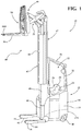
- a materials handling vehicle 10 (hereinafter “vehicle") is shown. While the present invention is described herein with reference to the illustrated vehicle 10, which comprises a forklift truck, it will be apparent to those skilled in the art that the present invention may be used in a variety of other types of materials handling vehicles.
- the vehicle 10 includes a main body or power unit 12, which includes a frame 14 defining a main structural component of the vehicle 10 and which houses a battery 15.
- the vehicle 10 further comprises a pair of fork-side support wheels 16 coupled to first and second outriggers 18, a driven and steered wheel 20 mounted near a first corner at a rear 12A of the power unit 12, and a caster wheel (not shown) mounted to a second corner at the rear 12A of the power unit 12.
- the wheels 16, 20 allow the vehicle 10 to move across a floor surface.
- An operator's compartment 22 is located within the power unit 12 for receiving an operator driving the vehicle 10.
- a tiller knob 24 is provided within the operator's compartment 22 for controlling steering of the vehicle 10.
- the speed and direction of movement (forward or reverse) of the vehicle 10 are controlled by the operator via a multi-function control handle 26 provided adjacent to an operator seat 28, which control handle 26 may control one or more other vehicle functions as will be appreciated by those having ordinary skill in the art.
- the vehicle 10 further includes an overhead guard 30 including a vertical support structure 32 affixed to the vehicle frame 14.
- a load handling assembly 40 of the vehicle 10 includes, generally, a mast assembly 42 and a carriage assembly 44, which is movable vertically along the mast assembly 42.
- the mast assembly 42 is positioned between the outriggers 18 and includes a fixed mast member 46 affixed to the frame 14, and nested first and second movable mast members 48, 50. It is noted that the mast assembly 42 may include additional or fewer movable mast members than the two shown in FIG. 1 , i.e., the first and second movable mast members 48, 50.
- the carriage assembly 44 includes conventional structure including a reach assembly 52, a fork carriage 54, and fork structure comprising a pair of forks 56A, 56B.
- a movable assembly 47 as defined herein includes the lower and upper movable mast members 48, 50 and the carriage assembly 44.
- the mast assembly 42 may be configured as the monomast described in U.S. Patent No. 8,714,311 to Steven C. Billger et al., granted on May 6, 2014 and assigned to the applicant, Crown Equipment Corporation.
- the vehicle 10 of FIG. 1 is provided by way of example and many different types of materials handling trucks are contemplated within the scope of the present invention. As described in detail below, aspects of a vehicle control module are provided which allow a number of identical components to be utilized on various vehicles even though the vehicles may be of different types.
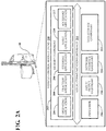
- FIG. 2A depicts a block-level view of a computing environment for providing control logic and software applications in a vehicle control module (VCM) 200, according to one or more embodiments shown and described herein.
- VCM vehicle control module
- the vehicle control module 200 and the way it interfaces with various operator controls and other functional systems of the vehicle 10 may be similar to control structure disclosed in U.S. Patent Publication Nos. 2010/0228428 and 2014/0188324 .
- the VCM is one of a number of cooperating modules, such as, in addition to a traction control module (TCM) or a steering control module (SCM), that cooperatively control operation of the vehicle 10.
- TCM traction control module
- SCM steering control module
- Each of the cooperating modules comprise one or more respective processors, memories storing executable program code, and other circuitry configured to perform their individual functions, as well as communicate with one another, as described in detail below.
- the TCM may also be referred to herein as a “traction controller” and the SCM may also be referred to herein as a “steering controller”.
- the VCM 200 includes one or more processors or microcontrollers 216, input/output hardware 218, network interface hardware 220, a data storage component 222, and a memory component 202.
- the data storage component 222 and the memory component 202 may each be configured as volatile and/or nonvolatile memory and as such, may include random access memory (including SRAM, DRAM, and/or other types of RAM), flash memory, secure digital (SD) memory, registers, compact discs (CD), digital versatile discs (DVD), and/or other types of non-transitory computer-readable mediums. Any stored information that is intended to be available after the vehicle 10 is shutdown and restarted may beneficially be stored in non-volatile memory. Also, depending on the particular embodiment, the non-transitory computer-readable medium, mentioned above, may reside within the VCM 200 and/or external to the VCM 200.
- the memory component 202 may store software or applications that can be executed (i.e., using executable code) by the one or more processors or microcontrollers 216.
- the memory component 202 may store an operating application or logic 204, a traction application or logic 208, a steering application or logic 206, a hoist application or logic 210, and accessory application(s) or logic 212.
- the operating logic 204 may include an operating system and other software such as, for example, diagnostic-related applications for managing components of the VCM 200.
- the traction application or logic 208 may be configured with one or more algorithms and parameters for facilitating optimal traction control for the vehicle 10.
- the steering application or logic 206 may be configured with one or more algorithms and parameters for facilitating optimal steering control of the vehicle 10.
- the hoist application or logic 210 may include one or more algorithms and parameters for facilitating optimal hoist control of the vehicle 10, which acts as the primary load handling assembly system used to raise and lower the moveable assembly 47 of the vehicle 10. Additionally, the accessory application or logic 212 may include one or more algorithms and parameters for providing control of accessories of the vehicle 10 such as an auxiliary load handling assembly system, which performs additional tasks such as tilt and sideshift of the carriage assembly 44.
- a local communication interface 214 is also included in FIG. 2A and may be implemented as a bus or other communication interface to facilitate communication among the components of the VCM 200.
- the one or more processors or microcontrollers 216 may include any processing component operable to receive and execute instructions (such as program code from the data storage component 222 and/or the memory component 202).
- the processors or microcontrollers 216 may comprise any kind of a device which receives input data, processes that data through computer instructions, and generates output data.
- a processor can be a microcontroller, a hand-held device, laptop or notebook computer, desktop computer, microcomputer, digital signal processor (DSP), mainframe, server, cell phone, personal digital assistant, other programmable computer devices, or any combination thereof.
- Such processors can also be implemented using programmable logic devices such as field programmable gate arrays (FPGAs) or, alternatively, realized as application specific integrated circuits (ASICs) or similar devices.
- FPGAs field programmable gate arrays
- ASICs application specific integrated circuits
- the input/output hardware 218 may include and/or be configured to interface with a monitor, positioning system, keyboard, touch screen, mouse, printer, image capture device, microphone, speaker, gyroscope, compass, and/or other device for receiving, sending, and/or presenting data.
- the network interface hardware 220 may include and/or be configured for communicating with any wired or wireless networking hardware, including an antenna, a modem, LAN port, wireless fidelity (Wi-Fi) card, WiMax card, mobile communications hardware, and/or other hardware for communicating with other networks and/or devices. From this connection, communication may be facilitated between the VCM 200 and other computing devices including other components coupled with a CAN bus or similar network on the vehicle 10.
- FIG. 2A is merely exemplary and are not intended to limit the scope of this disclosure. While the components in FIG. 2A are illustrated as residing within the VCM 200, this is merely an example. In some embodiments, one or more of the components may reside external to the VCM 200. It should also be understood that while the VCM 200 in FIG. 2A is illustrated as a single device; this is also merely an example. In some embodiments, the traction application 208, the steering application 206, the hoist application 210, and/or the accessory application 212 may reside on different devices.
- VCM 200 is illustrated with the traction application 208, the steering application 206, the hoist application 210, and the accessory application 212 as separate logical components, this is also an example.
- a single, composite software application may cause the VCM 200 to provide the described functionality.
- VCM 200 may communicate with various sensors and other control circuitry of the vehicle 10 to coordinate the various conditions of manual operation and automatic operation of the vehicle 10.
- FIG. 2B schematically illustrates selected features of a vehicle 10 and an example vehicle control module 200 that are helpful in describing vehicle control operations that utilize a traction application and steering application.
- the other features of the vehicle 10 and the VCM 200 described with respect to FIG. 1 and FIG. 2A are omitted from FIG. 2B so as not to obscure aspects of the example control of vehicle operations described herein.
- the VCM 200 includes a processor 216 illustrated to include the steering application 206, the traction application 208 and other applications (not shown) to be executed by the processor 216.
- the VCM 200 can include more than one microcontroller such as a master microcontroller and a slave microcontroller.
- an operator-controlled steering control input sensor 276 forming part of a steering control device comprising the tiller knob 24 of the vehicle 10 set out in FIG. 1 , provides sensor output signal values defining a steering command signal or signals 278 (e.g., an analog voltage) to the vehicle control module (VCM) 200.
- the steering control input sensor 276 may also form part of another steering control device comprising a steering wheel, a control handle, a steering tiller or like steering element.
- the steering command signals 278 may be adjusted or otherwise conditioned and may, for example, be provided to an input pin of the processor 216 within the VCM 200. That signal may be further conditioned and supplied as an input value to the steering application 206 that is being executed by the processor 216.
- the voltage for example, of the steering command signals 278, or the rate of change of that voltage, can vary based on the position and the rate of change of position of the steering control input sensor 276 associated with the steering control device, i.e., the tiller knob 24 in the illustrated embodiment.
- the steering application 206 Based on the input signal the steering application 206 receives that corresponds to the steering command signals 278, the steering application 206 determines a setpoint for a control attribute related to the steered wheel 20 of the vehicle.
- a voltage value can be used along with a lookup table to correlate the voltage value to a particular wheel angle value for a steering setpoint or the rate of change of the voltage could be multiplied by a predetermined scaling factor to convert that rate of change into the setpoint that changes a steering motor angular velocity.
- the control attribute may, for example, be a steered wheel angle or an angular velocity of a steering motor 274 and, therefore, a value of the setpoint may be a steered wheel angle ⁇ 1 or a steering motor angular velocity ⁇ 1 .
- the steering setpoint ⁇ 1 or ⁇ 1 can be provided to a steering control module (SCM) 272.
- SCM steering control module
- the SCM 272 uses the setpoint ⁇ 1 or ⁇ 1 for controlling a steering motor 274 which positions the steered wheel 20 to conform to a desired position as indicated by the operator's manipulation of the steering control input sensor 276.
- the SCM 272 can also provide a feedback value ⁇ 2 or ⁇ 2 of the control attribute related to the steered wheel.
- the feedback value is a measured, or actual, steered wheel angle ⁇ 2 of the steered wheel 20 or is a measured, or actual, angular velocity ⁇ 2 of the steering motor 274.
- the SCM 272 can, for example, provide the feedback value ⁇ 2 or ⁇ 2 to the steering application 206.
- the steering application 206 additionally produces the target steering angle ⁇ T or Wheel_Angle_Target which is provided to the traction application 208.
- a wheel angle/traction speed limiting process can be performed by the steering application 206 and the traction application 208 wherein the steering application 206 determines both:
- the traction torque setpoint ⁇ 1 can be provided to a traction control module (TCM) 258.
- TCM traction control module
- the TCM 258 uses the traction torque setpoint ⁇ 1 for controlling the operation of the traction motor 264 as discussed further below.
- the TCM 258 monitors the traction motor 264 and provides a traction feedback speed ⁇ 3 to the traction application 208 and the steering application 206. It may be beneficial in some embodiments to convert the traction speed, or speed feedback, ⁇ 3 , to an actual linear speed of the vehicle 10 by the traction application 208.
- the traction application 208 could scale that value to an actual linear speed, v 3 , of the vehicle 10 based on a) a gearing ratio between the traction motor 264 and the driven wheel 20 and b) the circumference of the driven wheel 20.
- the speed feedback ⁇ 3 was an angular speed of the driven wheel 20
- the traction application 208 could scale that value to an actual linear speed, v 3 , of the vehicle 10 based on the circumference of the driven wheel 20.
- the linear speed of the vehicle equals the linear speed of the driven wheel 20, presuming there is no slip at the driven wheel.
- the traction setpoint ⁇ 1 is determined by the traction application 208 using a Trx_Speed_Cmd which is generated by the traction application 208 and is based on traction speed command signals 260 received from an operator controlled traction speed control input sensor 262, such as the multi-function control handle 26 of the vehicle 10, and the target steering angle ⁇ T output from the steering application 206.
- the traction setpoint ⁇ 1 is output from the traction application 208 to the TCM 258 as a torque value which results in a corresponding speed of a traction motor 264 under the control of the TCM 258.
- mapping that exists between the motion of the steering control device and the motion of the steered wheel.
- This ratio determines the amount of motion the steered wheel realizes based on an amount of motion a driver imparts on the steering control device. As described below, this ratio is referred to as the "tiller-to-wheel" ratio.
- this "tiller-to-wheel” ratio corresponds to a scaling factor by which a steering control device angle can be multiplied to arrive at an associated steered wheel angle. If, for example, the steering control device is a tiller that moves between +/- 60 degrees to effect corresponding movement between +/- 90 degrees of the steered wheel, then the "tiller-to-wheel” ratio would be 90/60 or 1.5. Furthermore, if, for example, the amount the steered wheel is allowed to move during relatively higher speeds is also limited to +/- 60 degrees, then the "tiller-to-wheel” ratio would be 60/60 or 1.0.
- One or more lookup tables may be built each using a scaling factor corresponding to a design tiller-to-wheel ratio such that input of a steering control device position or angle into the table results in a table output of a corresponding steered wheel position or angle for a steering setpoint.
- One or more equations or functions each based on a scaling factor corresponding to a design tiller-to-wheel ratio may also be used to determine a steered wheel position or angle based on a steering control device position or angle.
- a first look up table may be built using a scaling factor of 1.0 for use during high traction speed operation of the vehicle, i.e., a high speed mode
- a second lookup table may be built using a scaling factor of 1.5 for use during low speed operation of the vehicle, i.e., a low speed mode.
- a speed selection switch (not shown) may be provided and is capable of being toggled between a high speed position corresponding to the high speed mode and a low speed position corresponding to a low speed mode. The first lookup table is used when the switch is in the high speed position and the second lookup table is used when the switch is in the low speed position.
- Varying the actual tiller-to-wheel ratio causes the steered wheel to be more or less sensitive to motion of the steering control device.
- the sensitivity of the steering control device can be reduced in accordance with the present invention so as to reduce movement of the steered wheel.
- the system and process for implementing desensitization of the steering control device to reduce the amount of resulting movement of the steered wheel relies on both the vehicle or traction speed and the handle angle.
- the system and process determines actual vehicle or traction speeds and handle angles that activate, deactivate, and determine the amount of desensitization.
- the phrase “steered wheel position” generally refers to an angle between a current position of the steered wheel and a reference axis, wherein the reference axis may be parallel or collinear with a straight line vehicle path such that the steered wheel position is 0 degrees when the vehicle is moving along the straight line path.
- reference axis may be parallel or collinear with a straight line vehicle path such that the steered wheel position is 0 degrees when the vehicle is moving along the straight line path.
- the phrase "tiller position” or “handle position” generally refer to an angle between a current position of the tiller/handle (or steering control device) and a reference axis or point, wherein the reference axis may be parallel or collinear with a straight line vehicle path and the reference point may fall on that straight line vehicle path such that tiller position/handle position/steering control device position is 0 degrees when the tiller/handle/steering control device is centered or positioned at a 0 degree angle relative the reference axis or point.
- “tiller/handle position” and “tiller/handle angle” can be used interchangeably.
- the term “raw handle angle” refers to a steering position value that is received from the steering control device.
- the term “processed handle angle” refers to a value that has been manipulated according to the desensitization logic in accordance with the present disclosure.
- aspects of the present disclosure relate to a processor implemented method for adjusting the position of a steered wheel of a vehicle, by adjusting the ratio between the steering control device and the steered wheel, when the traction speed and wheel angle values meet predefined conditions.
- the system commences desensitization, or in other words, moves from a nominal state to a desensitized state.
- the system removes the desensitization, or in other words, moves from a desensitized state to a nominal state.
- the control device-to-wheel ratio may move from nominal to desensitized, and back, repeatedly as conditions vary.
- the steering application 206 determines a setpoint for a control attribute related to the steered wheel 20 of the vehicle based on the input signal the steering application 206 receives that corresponds to the steering command signals 278.
- the voltage value from the steering control device i.e., the tiller knob 24 in the illustrated embodiment
- the voltage or steering position value from the steering control device corresponds to and defines an angular position of the steering control device and is referred to herein as a raw handle position.
- the raw handle position is adjusted to a different, processed handle position and, then the processed handle position is used to determine the steering setpoint, which effectively varies or modifies the design tiller-to-wheel ratio of the vehicle designed into the lookup table, equation or function.
- FIG. 3A depicts three handle angles utilized in implementing the desensitization logic in accordance with the present disclosure; each of the angles is measured relative to vertical axis 316 and, therefore, increase as the handle angle approaches the horizontal axis 318.
- the vertical axis is collinear with the reference axis, which, as noted above, may be parallel or collinear with a straight line vehicle path such that tiller position/handle position/steering control device position is 0 degrees when the tiller/handle/steering control device is centered or positioned at a 0 degree handle angle relative the reference axis.
- Handle angles can occur to the left of the vertical axis 316 as well and represent negative values between 0 and -90 degrees.
- the absolute value of the handle angle can be used when making comparisons of the angles to various predetermined thresholds.
- Angle 322 is an angle of the handle that represents the maximum angle at which the system can enter, or activate desensitization and can be referred to as a maximum commencement steer angle or a maximum initiation angle MaxInitAngle.
- desensitization can be activated when the magnitude of the angle of the handle is at or below the maximum initiation angle 322 and the vehicle traction speed TrxSpd reaches or exceeds a traction speed breakpoint TrxSpdBp as discussed more fully below.
- An alternative example is when the vehicle TrxSpd is at or above the traction speed setpoint TrxSpdBp but the magnitude of the angle of the handle is greater than the maximum initiation angle MaxInitAngle.
- Angle 320 is an angle of the handle that determines when a transition region begins as the handle angle magnitude increases and can be referred to as maximum angle numbness MaxAngleNmbns (also referred to herein as the "maximum numbness angle").
- the transition region extends from the MaxAngleNmbns angle for an increasing angular region defined by an angle referred to as numbness transition angle NmbnsTransAng.
- angle 324 represents an end to the transition region and equals the sum of MaxAngleNmbns and NmbnsTransAng.
- MaxInitAngle can be between about 0.5 to 1.5 degrees
- MaxAngleNmbns can be between about 9.0 and 11.0 degrees
- NmbnsTransAng can be between about 1.5 to 2.5 degrees such that maximum desensitization angle 324 can be between about 10.5 and 13.5 degrees.
- the qualifying term "about" in the previous sentence contemplates discrepancies of +/- 0.1 degrees.
- alternative angle sizes for any or all three of the angles 320, 322, 324 are contemplated within the scope of the present disclosure.
- FIG. 3B is a flowchart of an example method of determining whether or not the current vehicle conditions are sufficient to activate/deactivate steered wheel desensitization in accordance with the present disclosure.
- step 350 a value for both a traction speed breakpoint TrxSpdBp and a maximum commencement angle MaxInitAngle 322 may be determined.
- a table may be available in memory within, or accessible by, the VCM 200 that stores different allowable speeds for the vehicle.
- the table may include speed limit values that vary based on, for example, a current load present on the vehicle, a current steered wheel angle, a height of the forks of the vehicle, any fault conditions, and other factors readily recognized by one of ordinary skill in this field of endeavor. In this way, the maximum achievable speed of the vehicle when it is heavily loaded may be lower than the maximum achievable speed when the vehicle is not carrying any load.
- One of the traction speed limit values (e.g., the largest speed limit value, maximum traction speed TrxSpdMax) may be selected from the table and multiplied by a scale factor between 0 and 1 to determine a value corresponding to a traction speed breakpoint TrxSpdBp.
- the TrxSpdBp is compared to the TrxSpd and a raw handle position or current position of the steering control device HndlPosIn is compared to the MaxInitAngle.
- One condition is whether the absolute value of the measured traction wheel/motor speed is equal to or greater than the traction speed break point,
- the other condition is whether the absolute value of the handle or tiller angle (HndlPosIn) is less than or equal to the MaxInitAngle 322. If both conditions are true, then a status flag is set to a value (e.g., "1").
- the status flag is set to a different value (e.g., "0"). Based on the value of this status flag, steered wheel desensitization logic can determine whether desensitization of the steered wheel is activated or deactivated as described below.
- step 354 desensitization is activated and remains activated until vehicle conditions are such that desensitization of the steered wheel is deactivated. Accordingly, in step 356, a determination is made whether
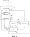
- FIG. 4 depicts a state machine representation of controlling a tiller-to-wheel ratio in accordance with the present disclosure.
- the state machine can be in one of a finite number of states.
- the state machine is in only one state at a time; the state it is in at any given time is called the current state. It can change from one state to another when initiated by a triggering event or condition; this is called a transition.
- a particular state machine is defined by a list of its states, its initial state, and the triggering condition for each transition.
- Inputs to the example state machine include a raw tiller (or handle) position (or angle), the current vehicle or traction motor speed TrxSpd, the traction speed breakpoint TrxSpdBp, the maximum traction speed TrxSpdMax.
- the above-mentioned status flag from the discussion of FIG. 3B is represented by transition 426 described below in relation to FIG. 4 .
- the output of the state machine is a processed handle, or tiller, position.
- the processed handle position is used by the steering application to cause the SCM 272 to move the steered wheel angle in a desired manner.
- the example state machine includes 6 states and 2 functions with one state merely being an initial state to represent how the state machine is entered.
- the 6 states include:
- the state machine transitions 420 from its initial state 402 to the WAIT_FOR_HANDLE_IN_RANGE state 404.
- One condition for moving from the nominal subset 401 to the desensitized subset 403 in the illustrated embodiment is that the absolute value of the raw handle angle be equal to or less than the particular angle referred to as the maximum initiation angle MaxInitAngle 322, as described above with respect to FIG. 3A and FIG. 3B .
- MaxInitAngle the absolute value of the raw handle angle is greater than MaxInitAngle, the system does not move from subset 401 (nominal) to subset 403 (desensitized) because the change from nominal to desensitized would create a noticeable adjustment of the wheel angle.
- one condition for applying desensitization is that the absolute value of the steered wheel angle, rather than the raw handle angle, be equal to or less than a maximum initiation/commencement angle 322.
- MaxInitAngle 322 is selected such that the change in the actual or real tiller-to-wheel ratio as a result of the processed handle angle output, at the time the desensitization is activated, produces an imperceptible change in the steered wheel angle, i.e., as the steered wheel moves to its updated angle.
- desensitization is not activated unless the angle of the steered wheel is sufficiently small such that when desensitization is initiated causing some movement of the steered wheel to an updated steered wheel position, this movement is unperceivable or nearly unperceivable as seen or experienced by the operator.
- the one triggering event for this state is if the absolute value of the raw handle angle becomes equal to or less than MaxInitAngle 322, then execution proceeds with a transition 422 to the WAIT_FOR_TrxSpd_IN_RANGE state 406.
- the state machine remains in the WAIT_FOR_TrxSpd_IN_RANGE state 406 until one of two triggering events occurs.
- One triggering event is if the absolute value of the raw handle angle increases above MaxInitAngle 322, then the state machine transitions 424 back to the WAIT_FOR_HANDLE_IN_RANGE state 404.
- the other triggering event is if the magnitude of the TrxSpd is equal to or increases above, TrxSpdBp, then the state machine transitions 426 to the HANDLE_ANGLE_IN_NUMBING_RANGE state 408 and to the desensitized subset 403.
- the value of the status flag set as discussed above with regards to FIG. 3B provides an example technique to determine when both triggering events occur.
- the status flag is set to a value (e.g., "1"). Accordingly, activation of desensitization will only commence when the absolute value of the raw handle angle is equal to or below MaxInitAngle and the absolute value of the TrxSpd is greater than or equal to TrxSpdBp.
- the state machine With the state machine in the HANDLE_ANGLE_IN_NUMBING_RANGE state 408, desensitization can be applied.
- the state machine remains in the HANDLE_ANGLE_IN_NUMBING_RANGE state 408 until one of two triggering events occur.
- One triggering event is if the absolute value of the TrxSpd falls below TrxSpdBp, then the state machine transitions 440 to the TrxSpd_BELOW_RANGE state 410.
- the other triggering event is if the absolute value of the raw handle angle increases to be equal to or above a predetermined maximum angle numbness MaxAngleNmbns 320, then the state machine transitions 432 to the HANDLE_ANGLE_IN_TRANSITION_RANGE state 412.
- an amount of desensitization applied is proportional to the magnitude of the TrxSpd such that the handle, steering control device or tiller, must realize more movement to get the same amount of movement of the steered wheel that was produced at a lower TrxSpd with less handle movement.
- the amount of desensitization can, for example, be calculated using the steps depicted in the flowchart of FIG. 5 .
- the inputs to this calculation include the TrxSpd, TrxSpdBp, TrxSpdMax values and a raw handle position while the output is a desensitized handle position or the processed handle angle.
- Tlr2DuNom a nominal tiller-to-wheel ratio
- Tlr2DuSf a ratio scale factor
- a first difference is calculated by subtracting the TrxSpdBp from the absolute value of the TrxSpd and, in step 504, a second difference is calculated by subtracting TrxSpdBp from the maximum speed TrxSpdMax.
- the first difference is divided by the second difference to calculate a first quotient.
- step 506 the first difference is divided by the second difference to calculate a first quotient.
- This first quotient represents the portion of the TrxSpd in the desensitization range (i.e., the speed range from 8 to 3) as compared to the entire desensitization range (i.e., the speed range from 12 to 3).
- step 508 an amount that the ratio scale factor Tlr2DuSf exceeds "1" is calculated and, in step 510, this amount is multiplied with the nominal tiller-to-wheel ratio Tlr2DuNom to calculate a first product that represents the change in the tiller-to-wheel ratio that can occur during desensitization.
- This first product is multiplied with the first quotient, in step 512, to produce a second product that is a value that is added to the nominal tiller-to-wheel ratio, in step 514 to produce a first sum.
- This first sum represents a numbed or desensitized tiller-to-wheel ratio NmbnsTlr2Du.
- the ratio scale factor Tlr2DuSf 2.35
- the numbed or desensitized tiller-to-wheel ratio is also referred to herein as a steering desensitization value.
- the numbed tiller-to-wheel ratio can be clipped such that it does not exceed the nominal tiller-to-wheel ratio Tlr2DuNom multiplied by the ratio scale factor Tlr2DuSf nor does it fall below the nominal tiller-to-wheel ratio Tlr2DuNom.
- the raw handle position is then divided by the numbed tiller-to-wheel ratio, in step 518, to calculate a handle position output value HndlPosOutNumbRng that is the desensitized handle position and is referred to above as the "processed handle position".
- the desensitized, or processed, handle position will be smaller (in magnitude) than the raw handle position reflecting that the movement of the handle by the operator is treated as if it is less than it actually is.
- the steering application 206 determines the steering setpoint based on the processed handle position, i.e., the processed handle position is used as an input into one of the first or the second lookup table such that the output from the lookup table is the steering setpoint.
- the output from the lookup table will be smaller than a value output from the lookup table had the raw handle position been used.
- the steering setpoint will result in an actual or effective tiller-to-wheel ratio that is smaller than the design tiller-to-wheel ratio, resulting in the steering being desensitized.
- the second product that was calculated in step 512 is dependent on the absolute value of the TrxSpd and increases as the magnitude of the TrxSpd increases which causes the first sum to increase as well.
- Desensitization continues in state 408 until the vehicle reaches its maximum speed as long as the handle position remains below the predetermined maximum angle numbness, MaxAngleNmbns 320. In contrast, when the speed of the vehicle decreases (but remains equal to or above TrxSpdBp), the desensitization is reduced.
- the state machine transitions 432 from the HANDLE_ANGLE_IN_NUMBING_RANGE state 408 to the HANDLE_ANGLE_IN_TRANSISTION RANGE state 412 as the absolute value of the raw handle angle increases and reaches the predetermined maximum angle numbness, MaxAngleNmbns 320.
- desensitization is gradually removed and done so in a way that is imperceptible to the operator. As described in detail below with respect to FIG.
- the desensitization is gradually removed over a range of angles from the MaxAngleNmbns 320 to a larger angle 324 calculated by adding the offset value NmbnsTransAng to the MaxAngleNmbns 320, in order to once again rely on the nominal or design tiller-to-wheel ratio, i.e., the raw handle position is used as an input into one of the first or the second lookup table, once the raw handle position reaches the larger angle 324.
- FIG. 6A depicts an example algorithm for calculating a processed handle position value while in the transition region in accordance with the present disclosure.
- FIG. 6B and FIG. 6C depict values from example calculations performed in accordance with FIG. 6A , where the numerical values are not actual handle position values and are used only to illustrate the steps set out in FIG. 6A .
- a second sum s 2 is calculated by adding MaxAngleNmbns+NmbnsTransAng and used to calculate, in step 604, a fourth difference d 4 by subtracting the absolute value of the raw handle position from the second sum s 2 .
- a first intermediate value i 1 is determined to be the maximum of the NmbnsTransAng and "1.5".
- a second quotient q 2 is calculated by dividing d 1 by i 1 .
- the second quotient q 2 generally represents an amount of the transition region remaining for the handle position to travel through. As the raw handle position approaches MaxAngleNmbns+NmbnsTransAng, the second quotient q 2 becomes smaller.
- a third quotient q 3 is determined by dividing the absolute value of the raw handle position
- the third quotient q 3 is used in step 612 to calculate a fifth difference, ds, by subtracting the Tlr2DuNom from the third quotient q 3 .
- This difference d 5 represents a maximum amount of desensitization that can be applied based on the current traction speed TrxSpd of the vehicle or traction motor.
- this difference ds is scaled based on the second quotient q 2 to produce a third product p 3 .
- p 3 is at its largest; and when the raw handle position is at MaxAngleNmbns+NmbnsTransAng 324, p 3 is at or near "0".
- a third sum s 3 is calculated by adding the third product p 3 to the nominal tiller-to-wheel ratio Tlr2DuNom.
- the third sum s 3 can be optionally clipped so as to be at least Tlr2DuNom and no greater than a value calculated in step 624.
- a second intermediate value i 2 is determined to be the maximum of "1" and the ratio scale factor Tlr2DuSf. Accordingly, in step 624, a fourth product p 4 can be calculated by multiplying the second intermediate value i 2 by the nominal tiller-to-wheel ratio Tlr2DuNom and is used as the upper clip limit for the modified tiller-to-wheel ratio.
- a fourth quotient q 4 is calculated by dividing the raw handle position by the third sum s 3 .
- the fourth quotient q 4 is the processed handle position that is output by the state machine and used by the steering application to determine the steering setpoint.
- the third sum s 3 approaches the nominal tiller-to-wheel ratio. As mentioned above, at relatively high speeds, this ratio is typically "1" such that at the upper edge of the transition region, the fourth quotient q 4 , or the processed handle position, is equal to the raw handle position and, thus, desensitization has been removed.
- FIG. 6B depicts values from example calculations performed in accordance with FIG. 6A , where the numerical values are not actual handle position values and are used only to illustrate the steps set out in FIG. 6A .
- TrxSpd is 100% of the TrxSpdMax
- MaxAngleNmbns is "2”
- NmbnsTransAng is "4"
- Tlr2DuSF is "2.35"
- Tlr2DuNom is "1”.
- the second column shows the raw handle position increasing from "2” (i.e., MaxAngleNmbns) to "6” (i.e., MaxAngleNmbns+NmbnsTransAng).
- Each of the other columns correspond to one of the steps of the flowchart of FIG. 6A .
- the right-most column shows the processed handle position as compared to its corresponding raw handle position wherein each processed handle position is calculated by dividing each corresponding raw handle position by the appropriate value in the column labeled "STEP 616".
- the values in the column labeled "STEP 616" decrease from Tlr2DuSF to Tlr2DuNom such that when the raw handle position is "6" desensitization of the handle position has been removed (i.e., the processed handle position equals the raw handle position.)
- FIG. 6C depicts values from example calculations performed in accordance with FIG. 6A , where the numerical values are not actual handle position values and are used only to illustrate the steps set out in FIG. 6A .
- TrxSpd is 75% of the TrxSpdMax and all the other parameters are the same as in FIG. 6B .
- the second column shows the raw handle position increasing from "2" (i.e., MaxAngleNmbns) to "6" (i.e., MaxAngleNmbns+NmbnsTransAng).
- Each of the other columns correspond to one of the steps of the flowchart of FIG. 6A .
- the right-most column shows the processed handle position as compared to its corresponding raw handle position wherein each processed handle position is calculated by dividing each corresponding raw handle position by the appropriate value in the column labeled "STEP 616".
- the values in the column labeled "STEP 616" decrease from "1.9” to Tlr2DuNom (i.e., "1") such that when the raw handle position is "6" desensitization of the handle position has been removed (i.e., the processed handle position equals the raw handle position.) Comparing the right-most columns of FIG. 6B and 6C , the processed handle positions in FIG.
- FIG. 6C are larger than a corresponding processed handle position in FIG. 6B which means that FIG. 6B represents greater desensitization of the steered wheel as compared to FIG. 6C .
- the TrxSpd of the vehicle decreases, the amount of desensitization decreases as well.
- the state machine When the state machine is in the TrxSpd_BELOW_RANGE state 410, there are two triggering conditions that cause transitions to another state. One of the two triggering conditions will be true so the state machine does not remain in the TrxSpd BELOW _RANGE state 410 but will always transition (428, 430) to a state in the subset 401. Thus, even though the TrxSpd BELOW _RANGE state 410 is in the subset 403 in FIG. 4 , the processed handle position output while in this state equals the raw handle position. If the absolute value of the raw handle position is equal to or less than MaxInitAngle, then the state machine transitions 428 to the WAIT_FOR_TrxSpd_IN_RANGE state 406. If the absolute value of the raw handle position is greater than MaxInitAngle, then the state machines transitions 430 to the WAIT FOR HANDLE IN RANGE state 404.
- FIG. 7 is a flowchart of an example method for implementing steering desensitization in accordance with the present disclosure.
- a steering position value of a steering control device of a vehicle is detected such that the steering position value corresponds to an angular position of the steering control device.
- a traction speed breakpoint TrxSpdBp is calculated, at or above which steering desensitization may occur.
- applying steering desensitization is also based on the steered wheel angle or the detected steering position value of the steering control device.
- a maximum commencement steer angle MaxInitAngle is defined, at or below which steering desensitization may be activated or commenced.
- step 708 a determination is made as to whether the angular position (magnitude) is equal to or less than the maximum commencement steer angle MaxInitAngle.
- step 710 an absolute value of the traction speed TrxSpd of one of a traction motor or a traction wheel of the vehicle is detected so that it can be determined in step 712 if the magnitude of the traction speed TrxSpd is equal to or above the traction speed breakpoint TrxSpdBp.
- a steering desensitization value can start being calculated when the angular position is equal to or less than the maximum commencement steer angle MaxInitAngle and the desensitization value continues to be calculated while the angular position remains below MaxAngleNmbns+NmbnsTransAng and the magnitude of the traction speed TrxSpd is equal to or above the traction speed breakpoint TrxSpdBp.
- a processed angular position can be calculated that is based on the steering desensitization value and the angular position of the steering control device. The processed angular position, rather than the calculated angular position, can be used in step 716 to calculate a wheel angle setpoint.
- a position of the steered wheel, ⁇ 2 or ⁇ 2 , of the vehicle can be adjusted to match the calculated wheel angle setpoint according to a delaying filter based on the traction speed of the vehicle TrxSpd.
- the steering system can position the steered wheel per the operator command as quickly as possible without operator perceived delay, but in order to improve operating stability, the steering application 206 of the VCM 200 may not immediately issue the calculated wheel angle setpoint to the SCM 272 based on the traction wheel/motor speed feedback or Trx_Speed but rather apply a slight delay. For example, a delay of less than 200 ms.
Landscapes
- Engineering & Computer Science (AREA)
- Transportation (AREA)
- Mechanical Engineering (AREA)
- Combustion & Propulsion (AREA)
- Chemical & Material Sciences (AREA)
- Structural Engineering (AREA)
- Physics & Mathematics (AREA)
- Geology (AREA)
- Mathematical Physics (AREA)
- Life Sciences & Earth Sciences (AREA)
- Civil Engineering (AREA)
- Artificial Intelligence (AREA)
- Evolutionary Computation (AREA)
- Computer Vision & Pattern Recognition (AREA)
- Medical Informatics (AREA)
- Software Systems (AREA)
- General Physics & Mathematics (AREA)
- Automation & Control Theory (AREA)
- Health & Medical Sciences (AREA)
- Steering Control In Accordance With Driving Conditions (AREA)
- Soil Working Implements (AREA)
- Discharge Lamp (AREA)
- Solid-Sorbent Or Filter-Aiding Compositions (AREA)
- Guiding Agricultural Machines (AREA)
Claims (15)
- Prozessorimplementiertes Verfahren zum Einstellen der Position eines gelenkten Rads (20) eines Fahrzeugs (10), das Folgendes umfasst:derartiges Erfassen (702), durch einen Prozessor (216), eines Lenkpositionswerts einer Lenksteuervorrichtung eines Fahrzeugs (10), dass der Lenkpositionswert einer Winkelposition der Lenksteuervorrichtung entspricht;Berechnen (704), durch den Prozessor (216), eines Traktionsgeschwindigkeitshaltepunkts, bei dem oder über dem eine Lenkdesensibilisierung auftreten kann;Definieren (706), durch den Prozessor (216), eines maximalen Anfangslenkwinkels, bei dem oder unter dem die Lenkdesensibilisierung anfangen kann;Bestimmen (708), durch den Prozessor (216), ob die Winkelposition der Lenksteuervorrichtung oder eine Winkelposition des gelenkten Rads (20) gleich oder kleiner als der maximale Anfangslenkwinkel ist;Erfassen (710), durch den Prozessor (216), einer Traktionsgeschwindigkeit eines Traktionsmotors (264) oder eines Traktionsrads des Fahrzeugs (10);Bestimmen (712), durch den Prozessor (216), ob die Traktionsgeschwindigkeit gleich ist oder über dem Traktionsgeschwindigkeitshaltepunkt liegt;Berechnen (714), durch den Prozessor (216), eines Lenkdesensibilisierungswerts, wenn die Winkelposition der Lenksteuervorrichtung oder des gelenkten Rads (20) gleich oder kleiner als der maximale Anfangslenkwinkel ist und die Traktionsgeschwindigkeit gleich ist oder über dem Traktionsgeschwindigkeitshaltepunkt liegt;Berechnen (716), durch den Prozessor (216), eines Radwinkelsollwerts basierend auf dem berechneten Lenkdesensibilisierungswert und der Winkelposition der Lenksteuervorrichtung; undEinstellen (718) einer Position des gelenkten Rads (20) des Fahrzeugs (10) basierend auf dem berechneten Radwinkelsollwert.
- Verfahren nach Anspruch 1, wobei das Berechnen (716) des Radwinkelsollwerts das Berechnen eines modifizierten Lenkpositionswerts durch Teilen des Lenkpositionswerts durch den Lenkdesensibilisierungswert umfasst.
- Verfahren nach Anspruch 1 oder 2, wobei das Berechnen (716) des Radwinkelsollwerts das Verwenden einer Nachschlagetabelle oder -funktion umfasst, die einen Eingabewert und einen Ausgabewert aufweist, wobei:der Eingabewert auf dem Lenkpositionswert basiert; undder Radwinkelsollwert auf dem Ausgabewert basiert;wobei der Eingabewert optional der modifizierte Lenkpositionswert ist; und der Ausgabewert optional der Radwinkelsollwert ist.
- Verfahren nach einem der vorhergehenden Ansprüche, wobei der Desensibilisierungswert basierend auf der Traktionsgeschwindigkeit variiert; und optional wobei der Desensibilisierungswert in Proportion zu der Traktionsgeschwindigkeit variiert.
- Verfahren nach einem der vorhergehenden Ansprüche, wobei der Desensibilisierungswert berechnet wird, während die Traktionsgeschwindigkeit bei dem oder über dem Traktionsgeschwindigkeitshaltepunkt verbleibt und die Winkelposition der Lenksteuervorrichtung unter einem maximalen Desensibilisierungswinkel verbleibt, der größer als der maximale Anfangslenkwinkel ist.
- Verfahren nach einem der vorhergehenden Ansprüche, wobei ein Skalierungsfaktor verwendet wird, um ein nominales Verhältnis von Lenksteuervorrichtung zu Rad zu modifizieren, um ein eingestelltes Verhältnis von Lenksteuervorrichtung zu Rad zu berechnen; und wobei der Desensibilisierungswert optional auf dem eingestellten Verhältnis von Lenksteuervorrichtung zu Rad multipliziert mit einem Quotienten basiert, der basierend auf der Traktionsgeschwindigkeit variiert.
- Verfahren nach einem vorhergehenden Anspruch, das Folgendes umfasst:
Erfassen einer Übergangszone, durch den Prozessor (216), wenn die Winkelposition der Lenksteuervorrichtung oder des gelenkten Rads (20) bei dem oder über einem maximalen Erstarrungswinkel, aber innerhalb eines zuvor bestimmten Winkelbereichs von dem maximalen Erstarrungswinkel, liegt; und wobei in der Übergangszone der Desensibilisierungswert optional in einer umgekehrten Proportion zu der Winkelposition der Lenksteuervorrichtung oder des gelenkten Rads (20) variiert. - Verfahren nach Anspruch 7, wobei in der Übergangszone der Desensibilisierungswert in Proportion zu der Traktionsgeschwindigkeit variiert.
- System zum Einstellen der Position eines gelenkten Rads (20) eines Fahrzeugs (10), das Folgendes umfasst:eine Speichervorrichtung (202), die ausführbare Anweisungen speichert; undeinen Prozessor (216) in Kommunikation mit der Speichervorrichtung (202), wobei der Prozessor (216) bei einem Ausführen der ausführbaren Anweisungen:einen Lenkpositionswert einer Lenksteuervorrichtung eines Fahrzeugs (10) derart erfasst, dass der Lenkpositionswert einer Winkelposition der Lenksteuervorrichtung entspricht;einen Traktionsgeschwindigkeitshaltepunkt berechnet, bei dem oder über dem eine Lenkdesensibilisierung auftreten kann;einen maximalen Anfangslenkwinkel definiert, bei dem oder unter dem die Lenkdesensibilisierung anfangen kann;bestimmt, ob die Winkelposition der Lenksteuervorrichtung oder eine Winkelposition des gelenkten Rads (20) gleich oder kleiner als der maximale Anfangslenkwinkel ist;eine Traktionsgeschwindigkeit eines Traktionsmotors (264) oder eines Traktionsrads des Fahrzeugs (10) erfasst;bestimmt, ob die Traktionsgeschwindigkeit gleich ist oder über dem Traktionsgeschwindigkeitshaltepunkt liegt;einen Lenkdesensibilisierungswert berechnet, wenn die Winkelposition der Lenksteuervorrichtung oder des gelenkten Rads (20) gleich oder kleiner als der maximale Anfangslenkwinkel ist und die Traktionsgeschwindigkeit gleich ist oder über dem Traktionsgeschwindigkeitshaltepunkt liegt;einen Radwinkelsollwert basierend auf dem berechneten Lenkdesensibilisierungswert und der Winkelposition der Lenksteuervorrichtung berechnet; undeine Position des gelenkten Rads (20) des Fahrzeugs (10) basierend auf dem berechneten Radwinkelsollwert einstellt.
- System nach Anspruch 9, wobei der Prozessor (216) bei dem Ausführen der ausführbaren Anweisungen:
einen modifizierten Eingabewert durch Dividieren des Lenkpositionswerts durch den Lenkdesensibilisierungswert berechnet. - System nach Anspruch 9 oder 10, wobei der Prozessor (216) bei dem Berechnen des Radwinkelsollwerts eine Nachschlagetabelle oder -funktion verwendet, die einen Eingabewert und einen Ausgabewert aufweist, wobei:der Eingabewert auf dem Lenkpositionswert basiert; undder Radwinkelsollwert auf dem Ausgabewert basiert; undwobei der Eingabewert optional der modifizierte Eingabewert ist; und der Ausgabewert optional der Radwinkelsollwert ist.
- System nach einem der Ansprüche 9 bis 11, wobei der Lenkdesensibilisierungswert basierend auf der Traktionsgeschwindigkeit variiert; und optional wobei der Lenkdesensibilisierungswert in Proportion zu der Traktionsgeschwindigkeit variiert.
- System nach einem der Ansprüche 9 bis 12, wobei der Desensibilisierungswert berechnet wird, während die Traktionsgeschwindigkeit bei dem oder über dem Traktionsgeschwindigkeitshaltepunkt verbleibt und die Winkelposition der Lenksteuervorrichtung unter einem maximalen Desensibilisierungswinkel verbleibt, der größer als der maximale Anfangslenkwinkel ist.
- System nach einem der Ansprüche 9 bis 13, wobei ein Skalierungsfaktor verwendet wird, um ein nominales Verhältnis von Lenksteuervorrichtung zu Rad zu modifizieren, um ein angepasstes Verhältnis von Lenksteuervorrichtung zu Rad zu berechnen; und wobei der Desensibilisierungswert optional auf dem angepassten Verhältnis von Lenksteuervorrichtung zu Rad multipliziert mit einem Quotienten basiert, der basierend auf der Traktionsgeschwindigkeit variiert.
- System nach einem der Ansprüche 9 bis 14, wobei der Prozessor (216) bei dem Ausführen der ausführbaren Anweisungen:eine Übergangszone erfasst, wenn die Winkelposition der Lenksteuervorrichtung oder des gelenkten Rads (20) bei dem oder über einem maximalen Erstarrungswinkel, aber innerhalb eines zuvor bestimmten Winkelbereichs von dem maximalen Erstarrungswinkel, liegt;wobei optional in der Übergangszone:i) der Lenkdesensibilisierungswert in einer umgekehrten Proportion zu der Winkelposition der Lenksteuervorrichtung oder des gelenkten Rads (20) variiert; und/oderii) der Desensibilisierungswert in Proportion zu der Traktionsgeschwindigkeit variiert.
Applications Claiming Priority (2)
| Application Number | Priority Date | Filing Date | Title |
|---|---|---|---|
| US201762445902P | 2017-01-13 | 2017-01-13 | |
| PCT/US2017/060990 WO2018132170A1 (en) | 2017-01-13 | 2017-11-10 | High speed straight ahead tiller desensitization |
Publications (2)
| Publication Number | Publication Date |
|---|---|
| EP3568332A1 EP3568332A1 (de) | 2019-11-20 |
| EP3568332B1 true EP3568332B1 (de) | 2021-11-03 |
Family
ID=60543693
Family Applications (1)
| Application Number | Title | Priority Date | Filing Date |
|---|---|---|---|
| EP17808258.2A Active EP3568332B1 (de) | 2017-01-13 | 2017-11-10 | Hochgeschwindigkeitsdesensibilisierung einer geradeaus laufenden fräse |
Country Status (7)
| Country | Link |
|---|---|
| US (2) | US10723382B2 (de) |
| EP (1) | EP3568332B1 (de) |
| KR (1) | KR102442228B1 (de) |
| CN (2) | CN113276946B (de) |
| AU (1) | AU2017393176B2 (de) |
| MX (1) | MX388262B (de) |
| WO (1) | WO2018132170A1 (de) |
Families Citing this family (5)
| Publication number | Priority date | Publication date | Assignee | Title |
|---|---|---|---|---|
| EP3568332B1 (de) | 2017-01-13 | 2021-11-03 | Crown Equipment Corporation | Hochgeschwindigkeitsdesensibilisierung einer geradeaus laufenden fräse |
| KR102884934B1 (ko) * | 2018-01-23 | 2025-11-12 | 파르텍 클러스터 컴피턴스 센터 게엠베하 | 응용 프로그램 런타임 결정된 이기종 계산 리소스의 동적 할당 |
| FI128300B (en) * | 2018-09-03 | 2020-03-13 | Rocla Oyj | Truck control |
| DE102019109466A1 (de) * | 2019-04-10 | 2020-10-15 | Linde Material Handling Gmbh | Flurförderzeug |
| EP4652090A1 (de) * | 2023-01-17 | 2025-11-26 | Mitsubishi Logisnext Europe Oy | Lenkung eines elektrischen gegengewichtslastkraftwagens |
Family Cites Families (204)
| Publication number | Priority date | Publication date | Assignee | Title |
|---|---|---|---|---|
| FR828405A (fr) * | 1936-10-31 | 1938-05-18 | Correcteur de sustentation pour véhicules automobiles ou remorqués contre les effets de la force centrifuge dans les virages, et contre les effets des dénivellations du sol porteur | |
| DE3003287A1 (de) | 1979-02-05 | 1980-08-14 | Volvo Ab | Selbststeuerndes fahrzeug |
| GB2125577B (en) | 1982-08-16 | 1986-09-24 | Nissan Motor | Self monitoring system |
| JPS6082482A (ja) * | 1983-10-14 | 1985-05-10 | Nissan Motor Co Ltd | パワ−ステアリングの流量制御装置 |
| GB8404062D0 (en) | 1984-02-16 | 1984-03-21 | Pa Consulting Services | Heat sealing thermoplastic straps |
| GB8431537D0 (en) | 1984-12-13 | 1985-01-23 | Ase Uk Ltd | Buckle |
| US4762194A (en) * | 1986-03-26 | 1988-08-09 | Mitsubishi Denki Kabushiki Kaisha | Motor-driven power steering system for a vehicle |
| US4942529A (en) | 1988-05-26 | 1990-07-17 | The Raymond Corporation | Lift truck control systems |
| DE3833213A1 (de) | 1988-09-30 | 1990-04-05 | Bosch Gmbh Robert | Vortriebsregeleinrichtung |
| DE4114047B4 (de) | 1991-04-29 | 2006-06-01 | Wabco Gmbh & Co.Ohg | Elektronisches Brems- oder Anfahrregelsystem für Fahrzeuge |
| DE4311485A1 (de) | 1993-04-07 | 1994-10-13 | Linde Ag | Verfahren zum Betreiben eines hydrostatischen Fahrantriebs |
| JP3577375B2 (ja) | 1995-09-28 | 2004-10-13 | 富士重工業株式会社 | 4輪駆動車のトラクション制御装置 |
| DE19702313C1 (de) | 1997-01-23 | 1998-04-02 | Daimler Benz Ag | Einrichtung zur Steuerung des Lenkwinkels eines Kraftfahrzeuges |
| KR100225961B1 (ko) | 1997-07-28 | 1999-10-15 | 추호석 | 전동지게차의 조향시스템 |
| WO1999008922A1 (fr) | 1997-08-13 | 1999-02-25 | Koyo Seiko Co., Ltd. | Systeme de direction assistee |
| JPH11310399A (ja) | 1998-04-27 | 1999-11-09 | Toyota Autom Loom Works Ltd | 産業車両の速度制御方法および速度制御装置 |
| US6502014B1 (en) | 1998-06-22 | 2002-12-31 | Continental Teves Ag & Co., Ohg | Regulating circuit for regulating the driving stability of a motor vehicle using a motor vehicle reference model |
| JP2000142065A (ja) | 1998-11-11 | 2000-05-23 | Komatsu Forklift Co Ltd | 産業車両の車軸固定制御装置 |
| JP2003500718A (ja) | 1999-05-19 | 2003-01-07 | ローベルト ボッシュ ゲゼルシャフト ミット ベシュレンクテル ハフツング | 車両内の電子的に制御される操作素子の,モデル支援される安全監視を具備する制御システム |
| US7275607B2 (en) * | 1999-06-04 | 2007-10-02 | Deka Products Limited Partnership | Control of a personal transporter based on user position |
| JP4988119B2 (ja) | 2000-03-27 | 2012-08-01 | コンティネンタル・テーベス・アクチエンゲゼルシヤフト・ウント・コンパニー・オッフェネ・ハンデルスゲゼルシヤフト | 車両操舵装置 |
| DE10032340A1 (de) | 2000-07-04 | 2002-01-31 | Bosch Gmbh Robert | Verfahren zum Lenken eines Fahrzeugs mit Servolenkung |
| US6456925B1 (en) | 2000-09-11 | 2002-09-24 | Deere & Company | Vehicle driven wheel speed control system |
| GB2391848B (en) | 2000-12-26 | 2004-08-18 | Nippon Yusoki Co Ltd | Power steering system |
| US6542801B2 (en) | 2000-12-26 | 2003-04-01 | Nippon Yusoki Co., Ltd. | Power steering system |
| DE10102523A1 (de) | 2001-01-20 | 2002-08-01 | Jungheinrich Ag | Verfahren zur Beeinflussung des Drehmoments an mindestens einem Antriebsrad eines Flurförderzeugs |
| US6879118B2 (en) | 2001-02-06 | 2005-04-12 | Robert Bosch Gmbh | Method for position regulation of an electric drive and for steering a motor vehicle by means of a steer-by-wire system |
| DE10205632A1 (de) | 2001-03-13 | 2002-10-02 | Bosch Gmbh Robert | Verfahren zur Positionsregelung eines elektrischen Antriebs und zum Lenken eines Kraftfahrzeugs mit einer Steer-by-Wire-Lenkung |
| DE10128357A1 (de) | 2001-06-13 | 2003-03-06 | Continental Teves Ag & Co Ohg | Verfahren zur Regelung der Fahrstabilität |
| US6640172B2 (en) | 2001-08-01 | 2003-10-28 | Delphi Technologies, Inc. | Dual gain algorithm for four wheel steering system |
| CA2396349C (en) | 2001-08-02 | 2006-01-24 | Kabushiki Kaisha Toyota Jidoshokki | Steering wheel position compensating apparatus in steering apparatus |
| US6658335B2 (en) * | 2001-10-11 | 2003-12-02 | Delphi Technologies, Inc. | Method and apparatus for motor velocity measurement compensation in electric power steering damping |
| JP4019873B2 (ja) | 2001-10-12 | 2007-12-12 | 日産自動車株式会社 | 舵角比制御装置 |
| JP3602497B2 (ja) | 2001-12-13 | 2004-12-15 | 住友ゴム工業株式会社 | ゴムクローラ |
| JP2003175843A (ja) | 2001-12-13 | 2003-06-24 | Nissan Motor Co Ltd | 舵角比可変装置 |
| DE10204742B4 (de) | 2002-01-19 | 2014-05-28 | Linde Material Handling Gmbh | Flurförderzeug mit einem Joystick zur Steuerung des Fahrantriebs, der Lenkanlage und der Bremsanlage |
| DE10213210A1 (de) | 2002-03-25 | 2003-10-16 | Still Gmbh | Flurförderzeug mit Ladefunktion |
| JP2003306160A (ja) | 2002-04-15 | 2003-10-28 | Nippon Yusoki Co Ltd | 荷役車両 |
| JP3868848B2 (ja) | 2002-05-23 | 2007-01-17 | 三菱電機株式会社 | 車両状態検出装置 |
| DE10233821A1 (de) | 2002-07-25 | 2004-02-05 | Daimlerchrysler Ag | Verfahren und Anordnung zur Steuerung der Energieversorgung einer wenigstens einen elektrischen Antriebsmotor aufweisenden, mobilen Vorrichtung mit einem hybriden Energiesystem, das ein Brennstoffzellensystem und ein dynamisches Energiesystem enthält |
| EP1388474B1 (de) * | 2002-08-05 | 2011-06-29 | Ford Global Technologies, LLC | System zur Bestimmung einer Regelgrösse zum Betrieb eines Wankregelungssystems |
| JP4140372B2 (ja) | 2002-12-18 | 2008-08-27 | 日産自動車株式会社 | 多重系車両操舵装置 |
| US6799104B2 (en) | 2003-01-13 | 2004-09-28 | Visteon Global Technologies, Inc. | System and method of controlling a vehicle steer-by-wire system applying robust control |
| AU2003902172A0 (en) | 2003-05-07 | 2003-05-22 | Dawson, Nicole | Accelerator pedal signal controller |
| US7025157B2 (en) | 2003-07-25 | 2006-04-11 | The Raymond Corporation | Pallet truck tiller arm with angle detector for speed select |
| JP4526792B2 (ja) | 2003-07-30 | 2010-08-18 | 株式会社アドヴィックス | トラクション制御装置 |
| US6971470B2 (en) | 2003-07-31 | 2005-12-06 | The Raymond Corporation | Control system for material handling vehicle with dual control handles |
| JP3966256B2 (ja) * | 2003-08-25 | 2007-08-29 | トヨタ自動車株式会社 | 電動式パワーステアリング装置用制御装置 |
| CN100436227C (zh) | 2003-10-02 | 2008-11-26 | 日产自动车株式会社 | 车辆转向装置 |
| DE10351162B4 (de) | 2003-11-03 | 2006-05-11 | Jungheinrich Ag | Gegengewichtsstapler mit einer Vorrichtung für eine elektrohydraulische oder elektrische Lenkung |
| DE10354663A1 (de) | 2003-11-22 | 2005-06-16 | Robert Bosch Gmbh | Vorrichtung und Verfahren zur Integration von variabler Lenkübersetzung und stabilisierendem Lenkeingriff |
| DE10355933B4 (de) | 2003-11-29 | 2015-04-09 | Still Gmbh | Hydrostatische Lenkvorrichtung |
| US7091685B2 (en) | 2004-01-22 | 2006-08-15 | Siemens Vdo Automotive Inc. | Overload protection for DC motors |
| JP2005253143A (ja) | 2004-03-02 | 2005-09-15 | Nippon Yusoki Co Ltd | 車両の走行制御装置 |
| GB2412902B (en) | 2004-04-07 | 2008-04-09 | Linde Ag | Industrial truck having increased static or quasi-static tipping stability |
| GB2413547B (en) | 2004-04-07 | 2007-06-06 | Linde Ag | Industrial truck having increased static/quasi-static and dynamic tipping stability |
| WO2005105550A1 (ja) | 2004-04-30 | 2005-11-10 | Nsk Ltd. | 電動パワーステアリング装置の制御装置 |
| DE102004021840A1 (de) | 2004-05-04 | 2005-12-01 | Liebherr-Werk Nenzing Gmbh, Nenzing | Lade- und/oder Hubgerät, insbesondere Reachstacker |
| DE202004007061U1 (de) | 2004-05-04 | 2005-09-22 | Liebherr-Werk Nenzing Gmbh, Nenzing | Telelader, insbesondere Reachstacker |
| US7017689B2 (en) | 2004-05-06 | 2006-03-28 | Crown Equipment Corporation | Electrical steering assist for material handling vehicles |
| US7222014B2 (en) | 2004-05-14 | 2007-05-22 | General Motors Corporation | Method for automatic traction control in a hybrid electric vehicle |
| DE102004028828A1 (de) | 2004-06-15 | 2006-01-05 | Zf Lenksysteme Gmbh | Verfahren zum Betrieb eines Lenksystems eines Kraftfahrzeugs |
| US7421328B2 (en) | 2004-09-07 | 2008-09-02 | Advics Co., Ltd. | Vehicle slip state determination system and traveling state control system |
| DE102004046890A1 (de) | 2004-09-28 | 2006-03-30 | Jungheinrich Ag | Verfahren zur Kippvermeidung von hinterradgelenkten Fahrzeugen, insbesondere Flurförderzeugen |
| GB2433791B (en) | 2004-10-22 | 2008-05-21 | Irobot Corp | Systems and Methods for Control of a Vehicle |
| US7452306B2 (en) | 2005-03-21 | 2008-11-18 | Caterpillar Inc. | Drive system having slip control |
| US7665555B2 (en) | 2005-04-19 | 2010-02-23 | Nmhg Oregon, Llc | Coast control system for an industrial vehicle |
| US7661493B2 (en) | 2005-04-19 | 2010-02-16 | Nmhg Oregon, Llc | Power assisted steering for motorized pallet truck |
| DE102005022089B4 (de) | 2005-05-12 | 2019-11-07 | Linde Material Handling Gmbh | Hydraulische Lenkeinrichtung |
| EP1914140B1 (de) | 2005-05-31 | 2012-07-18 | Kabushiki Kaisha Aichi Corporation | Fahrsteuervorrichtung für fahrzeug |
| DE102005024881A1 (de) | 2005-05-31 | 2006-12-07 | Still Gmbh | Flurförderzeug mit einer elektrischen Steuerungseinheit |
| US7931113B2 (en) | 2005-07-05 | 2011-04-26 | Fuji Jukogyo Kabushiki Kaisha | Steering control system for vehicle |
| DE202005011503U1 (de) | 2005-07-21 | 2006-11-30 | Liebherr-Werk Nenzing Gmbh, Nenzing | Flurförderfahrzeug |
| DE602005019047D1 (de) | 2005-09-20 | 2010-03-11 | Atlet Ab | Verbessertes Kontrollsystem für ein Flurförderfahrzeug |
| JP4793134B2 (ja) | 2005-09-30 | 2011-10-12 | 株式会社豊田自動織機 | フォークリフトの走行制御装置 |
| US20070212680A1 (en) | 2006-03-09 | 2007-09-13 | Roche Molecular Systems, Inc. | Safety approach for diagnostic systems |
| US20070295545A1 (en) * | 2006-05-11 | 2007-12-27 | Romig Bernard E | Differential Steering and Traction Control For Electrically Propelled Mower |
| JP4894388B2 (ja) | 2006-07-21 | 2012-03-14 | 日産自動車株式会社 | 操舵機構制御装置及び自動車 |
| GB2440322B (en) * | 2006-07-25 | 2011-07-06 | Advanced Vehicle Concepts Ltd | Wheeled vehicle |
| DE102006035863B4 (de) | 2006-08-01 | 2022-07-21 | Linde Material Handling Gmbh | Lenkvorrichtung für ein Flurförderzeug |
| DE102006041254B4 (de) | 2006-09-02 | 2010-04-08 | Jungheinrich Aktiengesellschaft | Verfahren zur Überprüfung einer elektrischen Lenkung sowie Flurförderzeug mit elektrischer Lenkung |
| EP3382668B1 (de) | 2006-09-14 | 2020-01-08 | Crown Equipment Corporation | Systeme und verfahren zur fernsteuerung eines materialhandhabungsfahrzeugs |
| US8452464B2 (en) * | 2009-08-18 | 2013-05-28 | Crown Equipment Corporation | Steer correction for a remotely operated materials handling vehicle |
| DE102006050506B4 (de) | 2006-10-26 | 2017-09-28 | Robert Bosch Automotive Steering Gmbh | Verfahren zur Einstellung eines Solllenkmoments in einem Lenksystem eines Fahrzeugs |
| JP4333729B2 (ja) | 2006-11-21 | 2009-09-16 | トヨタ自動車株式会社 | 車両挙動制御装置 |
| US10013815B2 (en) | 2006-12-13 | 2018-07-03 | Crown Equipment Corporation | Information system for industrial vehicles |
| KR100847491B1 (ko) | 2007-03-20 | 2008-07-21 | 대성전기공업 주식회사 | 조향각센서 오류검출 장치 및 방법 |
| JP2008296602A (ja) | 2007-05-29 | 2008-12-11 | Nippon Yusoki Co Ltd | 荷役車両の制御装置 |
| US8308174B2 (en) | 2007-06-04 | 2012-11-13 | Continental Teves Ag & Ohg | Steering device for adjusting a wheel steering angle |
| US8235161B2 (en) | 2007-07-06 | 2012-08-07 | Nmhg Oregon, Llc | Multiple-position steering control device |
| US8051687B2 (en) * | 2007-10-31 | 2011-11-08 | GM Global Technology Operations LLC | Traction steer detection and compensation |
| JP4329859B2 (ja) | 2007-12-12 | 2009-09-09 | トヨタ自動車株式会社 | 操舵制御装置 |
| US8521384B2 (en) | 2008-01-28 | 2013-08-27 | Textron Innovations Inc. | Turf maintenance vehicle all-wheel drive system |
| MX2008014783A (es) | 2008-02-05 | 2009-08-27 | Krueger Int Inc | Armazon para silla con soporte hueco ergonomico integral. |
| US7894958B2 (en) * | 2008-02-11 | 2011-02-22 | Caterpillar Inc | Traction control system |
| DE102008011719A1 (de) | 2008-02-28 | 2009-09-03 | Jungheinrich Aktiengesellschaft | Bremssystem für ein Flurförderzeug |
| US8315751B2 (en) | 2008-02-29 | 2012-11-20 | GM Global Technology Operations LLC | Methods, program products, and systems for controlling braking in a hybrid vehicle |
| DE102008012007B4 (de) | 2008-03-01 | 2012-02-23 | Audi Ag | Verfahren zum Reduzieren einer Kipptendenz eines Kraftwagens und ein Lenksystem |
| JP4713610B2 (ja) * | 2008-03-31 | 2011-06-29 | 株式会社クボタ | 作業車の制御装置 |
| US8230976B2 (en) | 2008-04-16 | 2012-07-31 | The Raymond Corporation | Pallet truck with calculated fork carriage height |
| EP2112053B1 (de) * | 2008-04-25 | 2015-08-12 | Volvo Car Corporation | Gierstabilitäts-Regelsystem |
| EP2982554B1 (de) | 2008-05-05 | 2020-06-03 | Crown Equipment Corporation | Antriebsschlupfregelung für ein fahrzeug zur handhabung von materialien |
| JP2010012973A (ja) | 2008-07-04 | 2010-01-21 | Nsk Ltd | ドライビングシミュレータ、その制御方法およびその制御プログラム |
| DE102008033389A1 (de) | 2008-07-16 | 2010-01-21 | Still Gmbh | Verfahren zur Steuerung einer Lenkvorrichtung für ein Flurförderzeug |
| US8028789B2 (en) | 2008-07-31 | 2011-10-04 | GM Global Technology Operations LLC | Control adaptation of variable gear ratio steering |
| JP5514417B2 (ja) * | 2008-09-04 | 2014-06-04 | カヤバ工業株式会社 | 電動パワーステアリングの制御装置 |
| US8714311B2 (en) | 2008-09-12 | 2014-05-06 | Crown Equipment Corporation | Monomast for a materials handling vehicle |
| JP2010095354A (ja) | 2008-10-17 | 2010-04-30 | Sumitomonacco Materials Handling Co Ltd | フォークリフトの速度制限装置 |
| WO2010065864A2 (en) | 2008-12-04 | 2010-06-10 | Crown Equipment Corporation | Multiple zone sensing for materials handling vehicles |
| US8170751B2 (en) * | 2008-12-17 | 2012-05-01 | GM Global Technology Operations LLC | Detection of driver intervention during a torque overlay operation in an electric power steering system |
| US8725359B2 (en) | 2008-12-26 | 2014-05-13 | Komatsu Ltd. | Traction control device |
| US8494719B2 (en) | 2009-02-12 | 2013-07-23 | GM Global Technology Operations LLC | Method and apparatus for controlling active rear steering |
| JP5278031B2 (ja) | 2009-02-24 | 2013-09-04 | 日産自動車株式会社 | 駐車支援装置及び駐車支援方法 |
| CN102341287B (zh) | 2009-03-06 | 2014-06-18 | 丰田自动车株式会社 | 车辆行驶控制装置 |
| WO2010109676A1 (ja) | 2009-03-25 | 2010-09-30 | トヨタ自動車株式会社 | 車両の操舵装置 |
| US8140228B2 (en) | 2009-03-27 | 2012-03-20 | The Raymond Corporation | System and method for dynamically maintaining the stability of a material handling vehicle having a vertical lift |
| DE102009020157B4 (de) | 2009-05-06 | 2021-07-01 | Volkswagen Ag | Verfahren und Vorrichtung zur Berechnung eines virtuellen Rotorwinkels |
| CN103645737A (zh) | 2009-08-18 | 2014-03-19 | 克朗设备公司 | 用于远程操作的材料搬运车辆的转向校正 |
| JP5072926B2 (ja) | 2009-09-03 | 2012-11-14 | 株式会社小松製作所 | 作業車両 |
| DE102009048092A1 (de) | 2009-10-02 | 2011-04-07 | Thyssenkrupp Presta Ag | Sicherheitseinrichtung für elektrische Servolenkung |
| KR20110067809A (ko) | 2009-12-15 | 2011-06-22 | 현대중공업 주식회사 | 지게차 오실레이팅 각도에 따른 주행속도 제어방법 |
| US8490723B2 (en) * | 2010-02-26 | 2013-07-23 | Segway, Inc. | Apparatus and methods for control of a vehicle |
| DE102010012887A1 (de) | 2010-03-26 | 2011-09-29 | Still Gmbh | Verfahren zur Steuerung eines elektrischen Antriebes einer mobilen Arbeitsmaschine, insbesondere eines Lenkantriebs |
| DE102010014317A1 (de) | 2010-04-09 | 2011-10-13 | Linde Material Handling Gmbh | Mobile Arbeitsmaschine, insbesondere Flurförderzeug |
| US8504238B2 (en) | 2010-04-16 | 2013-08-06 | Ford Global Technologies | Vehicle stability and steerability control via electronic torque distribution |
| DE102010029706A1 (de) | 2010-06-04 | 2011-12-08 | Robert Bosch Gmbh | Verfahren und Vorrichtung zur Erkennung von ungewollten Triebstrangreaktionen eines Kraftfahrzeuges mit wenigstens einem Antriebsaggregat |
| DE102010030144A1 (de) | 2010-06-16 | 2011-12-22 | Robert Bosch Gmbh | Parkhilfesystem zur Durchführung von Parkmanövern mit Lenkeingriff |
| DE102011082364A1 (de) | 2010-09-09 | 2012-03-22 | Continental Teves Ag & Co. Ohg | Lenkwinkelbestimmung für ein Kraftfahrzeug |
| US20120083950A1 (en) | 2010-09-30 | 2012-04-05 | GM Global Technology Operations LLC | Enhanced stability control for an electric powertrain |
| DE102010048958A1 (de) | 2010-10-18 | 2012-04-19 | Jungheinrich Aktiengesellschaft | Verfahren zum Betreiben einer elektrischen Lenkung eines Flurförderzeugs und hierfür vorgesehenes Flurförderzeug |
| US20120123614A1 (en) | 2010-11-17 | 2012-05-17 | INRO Technologies Limited | Method and apparatus for virtualizing industrial vehicles to automate task execution in a physical environment |
| US8543295B2 (en) | 2010-11-30 | 2013-09-24 | Christian Stanton Carver Bryant | Electronically controlled speed limiting system for turf care machine |
| GB2486177A (en) | 2010-12-02 | 2012-06-13 | Land Rover Uk Ltd | Traction control method that allows for processing time delays |
| KR20120067561A (ko) * | 2010-12-16 | 2012-06-26 | 현대중공업 주식회사 | 지게차 후륜 바퀴의 조향각 표시 장치 |
| CN102582678B (zh) * | 2011-01-11 | 2013-11-06 | 联创汽车电子有限公司 | 一种具有软件集成监控功能的电动助力转向系统 |
| DE102011013248B4 (de) | 2011-03-07 | 2021-02-11 | Jungheinrich Aktiengesellschaft | Verfahren und Vorrichtung zur Steuerung oder Regelung des Fahrbetriebs eines Flurförderzeugs |
| US8731785B2 (en) | 2011-03-18 | 2014-05-20 | The Raymond Corporation | Dynamic stability control systems and methods for industrial lift trucks |
| US8634986B2 (en) | 2011-03-30 | 2014-01-21 | GM Global Technology Operations LLC | Friction-based state of health indicator for an electric power steering system |
| DE102011016543A1 (de) | 2011-04-08 | 2012-10-11 | Jungheinrich Aktiengesellschaft | Verfahren zur Fahrzeuggeschwindigkeitsreduzierung bei einer Kurvenfahrt eines Flurförderzeugs |
| US9335163B2 (en) * | 2011-04-19 | 2016-05-10 | Ford Global Technologies, Llc | Trailer length estimation in hitch angle applications |
| JP2012254705A (ja) | 2011-06-08 | 2012-12-27 | Jtekt Corp | 車両用操舵装置及び荷役車両 |
| US9845012B2 (en) | 2011-07-06 | 2017-12-19 | General Electric Company | System and method for predicting mechanical failure of a motor |
| JP5445532B2 (ja) | 2011-07-27 | 2014-03-19 | 株式会社デンソー | 車両制御装置、車両制御プログラム、および車両制御方法 |
| JP2013039874A (ja) | 2011-08-16 | 2013-02-28 | Hitachi Constr Mach Co Ltd | 作業車両 |
| CN103842281B (zh) | 2011-08-29 | 2016-04-27 | 克朗设备公司 | 叉车导航系统 |
| BR112014004817A2 (pt) | 2011-08-29 | 2017-05-30 | Crow Equipment Corp | sistema para prover uma interface de controle de navegação veicular, e, veículo |
| US8965633B2 (en) * | 2011-09-02 | 2015-02-24 | GM Global Technology Operations LLC | System and method for speed adaptive steering override detection during automated lane centering |
| EP2753570A1 (de) | 2011-09-09 | 2014-07-16 | Eaton Corporation | Visuelles feedbacksystem für gelenkte räder in einem lenksystem mit veränderlicher rate |
| BR112014016883A8 (pt) | 2012-01-25 | 2017-07-04 | Crown Equip Corp | método para monitorar de maneira dinâmica um ou mais sistemas de tração de um veículo industrial, e, veículo industrial |
| ITBO20120038A1 (it) | 2012-01-27 | 2013-07-28 | Ferrari Spa | Metodo ed unita' di controllo di un sistema di sterzatura di una vettura stradale |
| US20140143607A1 (en) | 2012-02-10 | 2014-05-22 | Phoenix Contact Development & Manufacturing, Inc. | Dedicated Network Diagnostics Module for a Process Network |
| JP5852471B2 (ja) | 2012-02-28 | 2016-02-03 | 株式会社豊田中央研究所 | 車両制御装置、操舵模擬装置、及びプログラム |
| DE102012102459A1 (de) | 2012-03-22 | 2013-09-26 | Continental Automotive Gmbh | Verfahren zur Anpassung wenigstens eines Steuerungsparameters eines sicherheitsrelevanten Systems eines Fahrzeugs |
| DE102012209788B4 (de) | 2012-06-12 | 2022-08-11 | Zf Friedrichshafen Ag | Steuergerät und Verfahren zur Ausgabe eines Steuersignals ansprechend auf ein eingelesenes Pedalauslenkungssignal |
| EP2674387B8 (de) | 2012-06-12 | 2015-07-15 | UniCarriers Europe AB | Industrielastkraftwagen mit verbesserter Kurvenfahrtsteuerung |
| US20130338885A1 (en) | 2012-06-15 | 2013-12-19 | John B. Kirk | Management system embedded in an industrial vehicle |
| JPWO2013190821A1 (ja) | 2012-06-19 | 2016-02-08 | 住友重機械工業株式会社 | フォークリフト用のモータ駆動装置およびそれを用いたフォークリフト |
| DE102012105831B4 (de) | 2012-07-02 | 2020-06-25 | Hubtex Maschinenbau Gmbh & Co. Kg | Lenksystem für ein Fahrzeug |
| CN202806864U (zh) * | 2012-08-30 | 2013-03-20 | 浙江诺力机械股份有限公司 | 一种步行式电动工业车辆电转向控制装置 |
| JP5973856B2 (ja) | 2012-09-18 | 2016-08-23 | 日立オートモティブシステムズ株式会社 | 電動パワーステアリング装置および電動パワーステアリング装置の制御装置 |
| JP5192605B1 (ja) | 2012-09-28 | 2013-05-08 | 株式会社小松製作所 | ホイールローダ |
| SE539154C2 (sv) | 2012-12-04 | 2017-04-18 | Scania Cv Ab | Anordning och förfarande för förbättring av säkerhet vid framförande av ett fordon |
| ES2961652T3 (es) | 2012-12-19 | 2024-03-13 | Schneider Electric Usa Inc | Medidor de energía multifásico configurado para monitorizar el voltaje de la batería del generador |
| US9376299B2 (en) | 2013-01-09 | 2016-06-28 | Hyster-Yale Group, Inc. | Systems and methods for moving a pallet truck and raising a load |
| JP5418705B2 (ja) | 2013-01-24 | 2014-02-19 | 日産自動車株式会社 | 駐車支援装置及び駐車支援方法 |
| EP2960139B1 (de) | 2013-02-21 | 2017-02-15 | Nissan Motor Co., Ltd. | Lenksteuerungsvorrichtung für ein fahrzeug lenksteuerungsverfahren für ein fahrzeug |
| US20140278021A1 (en) | 2013-03-12 | 2014-09-18 | Cnh America, Llc | Steering wheel direction indicator for neutral start |
| US8918263B2 (en) | 2013-03-14 | 2014-12-23 | Clark Equipment Company | Traction control for power machine |
| US9002557B2 (en) | 2013-03-14 | 2015-04-07 | The Raymond Corporation | Systems and methods for maintaining an industrial lift truck within defined bounds |
| DE102014204097A1 (de) | 2013-03-15 | 2014-09-18 | Gm Global Technology Operations, Llc | Verfahren, Systeme und Vorrichtungen zum Reduzieren von Lenkradvibration bei elektrischen Lenkhilfesystemen |
| KR101447811B1 (ko) | 2013-04-05 | 2014-10-13 | 현대중공업 주식회사 | 속도 및 조향 센서를 이용한 지게차 전복 방지 제어 시스템 및 제어 방법 |
| JP6142658B2 (ja) | 2013-05-13 | 2017-06-07 | 日産自動車株式会社 | 車両用操舵制御装置及び車両用操舵制御方法 |
| CN105209324B (zh) | 2013-05-20 | 2018-05-25 | 罗伯特·博世有限公司 | 后轮转向控制 |
| GB201311515D0 (en) | 2013-06-27 | 2013-08-14 | Jaguar Land Rover Ltd | EV range prediction |
| KR101910675B1 (ko) | 2013-07-03 | 2018-10-22 | 현대건설기계 주식회사 | 지게차 조향 제한장치 |
| DE102013011883A1 (de) | 2013-07-17 | 2015-01-22 | Thyssenkrupp Presta Ag | Verfahren zum Betreiben der Lenkung eines Kranftfahrzeugs |
| US10521519B2 (en) | 2013-07-23 | 2019-12-31 | Atieva, Inc. | Induction motor flux and torque control with rotor flux estimation |
| JP6053651B2 (ja) * | 2013-09-20 | 2016-12-27 | 日立オートモティブシステムズ株式会社 | パワーステアリング装置および車両搭載機器の制御装置 |
| DE102013111168A1 (de) | 2013-10-09 | 2015-04-09 | Trw Automotive Gmbh | Verfahren zur Steuerung eines Elektromotors eines Servo-Lenksystems sowie Servo-Lenksystem |
| AU2014337806A1 (en) | 2013-10-24 | 2016-05-26 | Hyundai Heavy Industries Co., Ltd. | Forklift managing device |
| US9434415B2 (en) * | 2013-11-08 | 2016-09-06 | Ford Global Technologies, Llc | Tire windup compensation |
| KR20150063766A (ko) * | 2013-12-02 | 2015-06-10 | 주식회사 두산 | 지게차 |
| GB201401183D0 (en) | 2014-01-24 | 2014-03-12 | Jaguar Land Rover Ltd | Vehicle speed control system and method |
| US9926686B2 (en) | 2014-01-27 | 2018-03-27 | Komatsu Ltd. | Work vehicle and work vehicle emergency travelling method |
| DE102014202230A1 (de) * | 2014-02-07 | 2015-08-13 | Robert Bosch Gmbh | Verfahren und Vorrichtung zum Verhindern eines Kippens eines lenkbaren Fahrzeugs |
| CN106030425B (zh) | 2014-02-21 | 2019-03-29 | 西门子公司 | 用于选择程序功能的方法、设备和车辆、船舶或者飞机 |
| JP5935960B2 (ja) | 2014-03-25 | 2016-06-15 | 日本精工株式会社 | 電動パワーステアリング装置 |
| KR101526796B1 (ko) | 2014-04-01 | 2015-06-05 | 현대자동차주식회사 | 능동 전륜 조향 장치의 캐치업 방지 방법 및 이에 사용되는 장치 |
| WO2015152276A1 (ja) | 2014-04-03 | 2015-10-08 | ヤマハ発動機株式会社 | 駆動力制御システム、および駆動力制御システムを備えた車両 |
| SE539254C2 (sv) | 2014-05-21 | 2017-05-30 | Scania Cv Ab | Förfarande och system för anpassning av ett fordons hastighet vid kurvkörning |
| SE539938C2 (sv) | 2014-05-21 | 2018-01-30 | Scania Cv Ab | Förfarande och system för anpassning av ett fordons momentana hastighet i förhållande till en rattvinkels vinkelhastighet |
| US9381823B2 (en) | 2014-07-17 | 2016-07-05 | Ford Global Technologies, Llc | Real-time battery estimation |
| CN107406050B (zh) | 2015-03-31 | 2021-04-20 | 克朗设备公司 | 控制物料搬运车辆的功能系统的方法 |
| US9561820B2 (en) | 2015-06-30 | 2017-02-07 | Caterpillar Paving Products Inc. | Uncommanded steering detection |
| US10106171B2 (en) | 2015-07-28 | 2018-10-23 | Crown Equipment Corporation | Vehicle control module with signal switchboard and output tables |
| CA2991312C (en) | 2015-08-14 | 2023-09-19 | Crown Equipment Corporation | Steering and traction applications for determining a steering control attribute and a traction control attribute |
| MX390749B (es) | 2015-08-14 | 2025-03-21 | Crown Equip Corp | Diagnosticos basados en modelos de acuerdo con el modelo de direccion. |
| CN106005006B (zh) * | 2016-07-29 | 2018-02-16 | 北京合众思壮科技股份有限公司 | 一种转向角传感器的校准方法和装置 |
| CN106143263B (zh) * | 2016-08-30 | 2019-11-22 | 北京华力兴科技发展有限责任公司 | 驱动控制系统和集装箱和/或车辆检查载车 |
| DE102016222206A1 (de) | 2016-11-11 | 2018-05-17 | Ford Global Technologies, Llc | Verfahren zum Erfassen von Lenkungsfehlstellungen einer adaptiven Lenkung eines Kraftfahrzeugs |
| JP6462646B2 (ja) * | 2016-11-24 | 2019-01-30 | 本田技研工業株式会社 | 車両用制御装置 |
| EP3568332B1 (de) | 2017-01-13 | 2021-11-03 | Crown Equipment Corporation | Hochgeschwindigkeitsdesensibilisierung einer geradeaus laufenden fräse |
| KR102350703B1 (ko) | 2017-01-13 | 2022-01-13 | 크라운 이큅먼트 코포레이션 | 스티어 휠 동역학에 기초한 견인 속도 복구 |
| US10597070B2 (en) | 2017-09-29 | 2020-03-24 | GM Global Technology Operations LLC | Methods and systems for traction steer detection |
-
2017
- 2017-11-10 EP EP17808258.2A patent/EP3568332B1/de active Active
- 2017-11-10 WO PCT/US2017/060990 patent/WO2018132170A1/en not_active Ceased
- 2017-11-10 KR KR1020197023620A patent/KR102442228B1/ko active Active
- 2017-11-10 CN CN202110773142.1A patent/CN113276946B/zh active Active
- 2017-11-10 AU AU2017393176A patent/AU2017393176B2/en active Active
- 2017-11-10 US US15/808,962 patent/US10723382B2/en active Active
- 2017-11-10 CN CN201780073467.0A patent/CN110035944B/zh active Active
- 2017-11-10 MX MX2019008407A patent/MX388262B/es unknown
-
2020
- 2020-05-12 US US16/872,756 patent/US11400975B2/en active Active
Non-Patent Citations (1)
| Title |
|---|
| None * |
Also Published As
| Publication number | Publication date |
|---|---|
| MX2019008407A (es) | 2019-09-16 |
| CN110035944A (zh) | 2019-07-19 |
| CN113276946B (zh) | 2023-02-17 |
| US11400975B2 (en) | 2022-08-02 |
| US20180201316A1 (en) | 2018-07-19 |
| EP3568332A1 (de) | 2019-11-20 |
| MX388262B (es) | 2025-03-19 |
| KR20190107695A (ko) | 2019-09-20 |
| US10723382B2 (en) | 2020-07-28 |
| CN110035944B (zh) | 2021-09-17 |
| CN113276946A (zh) | 2021-08-20 |
| US20200269919A1 (en) | 2020-08-27 |
| KR102442228B1 (ko) | 2022-09-13 |
| CA3041343A1 (en) | 2018-07-19 |
| AU2017393176B2 (en) | 2023-05-11 |
| AU2017393176A1 (en) | 2019-05-30 |
| WO2018132170A1 (en) | 2018-07-19 |
Similar Documents
| Publication | Publication Date | Title |
|---|---|---|
| US11400975B2 (en) | High speed straight ahead tiller desensitization | |
| EP3568374B1 (de) | Zuggeschwindigkeitswiederaufnahme auf der grundlage eines dynamischen lenkrads | |
| US10996673B1 (en) | Manual override | |
| KR102756532B1 (ko) | 자율주행차량의 조향 제어 장치 및 방법 | |
| US10625773B2 (en) | Steer torque manager for an advanced driver assistance system of a road vehicle | |
| JP5994868B2 (ja) | 操舵制御装置 | |
| US9718492B2 (en) | Electric power steering apparatus | |
| US10589777B2 (en) | Steering control apparatus | |
| CN102470891B (zh) | 转向控制装置 | |
| JP5338491B2 (ja) | 車両用操舵装置および車両用操舵方法 | |
| KR20180007062A (ko) | 전동식 동력 조향장치의 조향복원 제어장치 및 방법 | |
| CA3041343C (en) | High speed straight ahead tiller desensitization | |
| KR20210080659A (ko) | 후륜 조향 제어 장치 및 후륜 조향 제어 방법 | |
| KR101978122B1 (ko) | 차량 쏠림 방지 방법 | |
| CA3039984C (en) | Traction speed recovery based on steer wheel dynamic | |
| CN102774417B (zh) | 转向装置、工业车辆及程序 | |
| JP6061802B2 (ja) | 電動パワーステアリング制御装置 | |
| JP2003026399A (ja) | フォークリフトの油圧制御装置 |
Legal Events
| Date | Code | Title | Description |
|---|---|---|---|
| STAA | Information on the status of an ep patent application or granted ep patent |
Free format text: STATUS: UNKNOWN |
|
| STAA | Information on the status of an ep patent application or granted ep patent |
Free format text: STATUS: THE INTERNATIONAL PUBLICATION HAS BEEN MADE |
|
| PUAI | Public reference made under article 153(3) epc to a published international application that has entered the european phase |
Free format text: ORIGINAL CODE: 0009012 |
|
| STAA | Information on the status of an ep patent application or granted ep patent |
Free format text: STATUS: REQUEST FOR EXAMINATION WAS MADE |
|
| 17P | Request for examination filed |
Effective date: 20190429 |
|
| AK | Designated contracting states |
Kind code of ref document: A1 Designated state(s): AL AT BE BG CH CY CZ DE DK EE ES FI FR GB GR HR HU IE IS IT LI LT LU LV MC MK MT NL NO PL PT RO RS SE SI SK SM TR |
|
| AX | Request for extension of the european patent |
Extension state: BA ME |
|
| DAV | Request for validation of the european patent (deleted) | ||
| DAX | Request for extension of the european patent (deleted) | ||
| GRAP | Despatch of communication of intention to grant a patent |
Free format text: ORIGINAL CODE: EPIDOSNIGR1 |
|
| STAA | Information on the status of an ep patent application or granted ep patent |
Free format text: STATUS: GRANT OF PATENT IS INTENDED |
|
| INTG | Intention to grant announced |
Effective date: 20201124 |
|
| GRAJ | Information related to disapproval of communication of intention to grant by the applicant or resumption of examination proceedings by the epo deleted |
Free format text: ORIGINAL CODE: EPIDOSDIGR1 |
|
| STAA | Information on the status of an ep patent application or granted ep patent |
Free format text: STATUS: REQUEST FOR EXAMINATION WAS MADE |
|
| INTC | Intention to grant announced (deleted) | ||
| GRAP | Despatch of communication of intention to grant a patent |
Free format text: ORIGINAL CODE: EPIDOSNIGR1 |
|
| STAA | Information on the status of an ep patent application or granted ep patent |
Free format text: STATUS: GRANT OF PATENT IS INTENDED |
|
| INTG | Intention to grant announced |
Effective date: 20210525 |
|
| GRAS | Grant fee paid |
Free format text: ORIGINAL CODE: EPIDOSNIGR3 |
|
| GRAA | (expected) grant |
Free format text: ORIGINAL CODE: 0009210 |
|
| STAA | Information on the status of an ep patent application or granted ep patent |
Free format text: STATUS: THE PATENT HAS BEEN GRANTED |
|
| AK | Designated contracting states |
Kind code of ref document: B1 Designated state(s): AL AT BE BG CH CY CZ DE DK EE ES FI FR GB GR HR HU IE IS IT LI LT LU LV MC MK MT NL NO PL PT RO RS SE SI SK SM TR |
|
| REG | Reference to a national code |
Ref country code: GB Ref legal event code: FG4D |
|
| REG | Reference to a national code |
Ref country code: AT Ref legal event code: REF Ref document number: 1443720 Country of ref document: AT Kind code of ref document: T Effective date: 20211115 Ref country code: CH Ref legal event code: EP |
|
| REG | Reference to a national code |
Ref country code: IE Ref legal event code: FG4D |
|
| REG | Reference to a national code |
Ref country code: DE Ref legal event code: R096 Ref document number: 602017048807 Country of ref document: DE |
|
| REG | Reference to a national code |
Ref country code: LT Ref legal event code: MG9D |
|
| REG | Reference to a national code |
Ref country code: NL Ref legal event code: MP Effective date: 20211103 |
|
| REG | Reference to a national code |
Ref country code: AT Ref legal event code: MK05 Ref document number: 1443720 Country of ref document: AT Kind code of ref document: T Effective date: 20211103 |
|
| PG25 | Lapsed in a contracting state [announced via postgrant information from national office to epo] |
Ref country code: RS Free format text: LAPSE BECAUSE OF FAILURE TO SUBMIT A TRANSLATION OF THE DESCRIPTION OR TO PAY THE FEE WITHIN THE PRESCRIBED TIME-LIMIT Effective date: 20211103 Ref country code: LT Free format text: LAPSE BECAUSE OF FAILURE TO SUBMIT A TRANSLATION OF THE DESCRIPTION OR TO PAY THE FEE WITHIN THE PRESCRIBED TIME-LIMIT Effective date: 20211103 Ref country code: FI Free format text: LAPSE BECAUSE OF FAILURE TO SUBMIT A TRANSLATION OF THE DESCRIPTION OR TO PAY THE FEE WITHIN THE PRESCRIBED TIME-LIMIT Effective date: 20211103 Ref country code: BG Free format text: LAPSE BECAUSE OF FAILURE TO SUBMIT A TRANSLATION OF THE DESCRIPTION OR TO PAY THE FEE WITHIN THE PRESCRIBED TIME-LIMIT Effective date: 20220203 Ref country code: AT Free format text: LAPSE BECAUSE OF FAILURE TO SUBMIT A TRANSLATION OF THE DESCRIPTION OR TO PAY THE FEE WITHIN THE PRESCRIBED TIME-LIMIT Effective date: 20211103 |
|
| PG25 | Lapsed in a contracting state [announced via postgrant information from national office to epo] |
Ref country code: IS Free format text: LAPSE BECAUSE OF FAILURE TO SUBMIT A TRANSLATION OF THE DESCRIPTION OR TO PAY THE FEE WITHIN THE PRESCRIBED TIME-LIMIT Effective date: 20220303 Ref country code: SE Free format text: LAPSE BECAUSE OF FAILURE TO SUBMIT A TRANSLATION OF THE DESCRIPTION OR TO PAY THE FEE WITHIN THE PRESCRIBED TIME-LIMIT Effective date: 20211103 Ref country code: PT Free format text: LAPSE BECAUSE OF FAILURE TO SUBMIT A TRANSLATION OF THE DESCRIPTION OR TO PAY THE FEE WITHIN THE PRESCRIBED TIME-LIMIT Effective date: 20220303 Ref country code: PL Free format text: LAPSE BECAUSE OF FAILURE TO SUBMIT A TRANSLATION OF THE DESCRIPTION OR TO PAY THE FEE WITHIN THE PRESCRIBED TIME-LIMIT Effective date: 20211103 Ref country code: NO Free format text: LAPSE BECAUSE OF FAILURE TO SUBMIT A TRANSLATION OF THE DESCRIPTION OR TO PAY THE FEE WITHIN THE PRESCRIBED TIME-LIMIT Effective date: 20220203 Ref country code: NL Free format text: LAPSE BECAUSE OF FAILURE TO SUBMIT A TRANSLATION OF THE DESCRIPTION OR TO PAY THE FEE WITHIN THE PRESCRIBED TIME-LIMIT Effective date: 20211103 Ref country code: LV Free format text: LAPSE BECAUSE OF FAILURE TO SUBMIT A TRANSLATION OF THE DESCRIPTION OR TO PAY THE FEE WITHIN THE PRESCRIBED TIME-LIMIT Effective date: 20211103 Ref country code: HR Free format text: LAPSE BECAUSE OF FAILURE TO SUBMIT A TRANSLATION OF THE DESCRIPTION OR TO PAY THE FEE WITHIN THE PRESCRIBED TIME-LIMIT Effective date: 20211103 Ref country code: GR Free format text: LAPSE BECAUSE OF FAILURE TO SUBMIT A TRANSLATION OF THE DESCRIPTION OR TO PAY THE FEE WITHIN THE PRESCRIBED TIME-LIMIT Effective date: 20220204 Ref country code: ES Free format text: LAPSE BECAUSE OF FAILURE TO SUBMIT A TRANSLATION OF THE DESCRIPTION OR TO PAY THE FEE WITHIN THE PRESCRIBED TIME-LIMIT Effective date: 20211103 |
|
| REG | Reference to a national code |
Ref country code: CH Ref legal event code: PL |
|
| PG25 | Lapsed in a contracting state [announced via postgrant information from national office to epo] |
Ref country code: SM Free format text: LAPSE BECAUSE OF FAILURE TO SUBMIT A TRANSLATION OF THE DESCRIPTION OR TO PAY THE FEE WITHIN THE PRESCRIBED TIME-LIMIT Effective date: 20211103 Ref country code: SK Free format text: LAPSE BECAUSE OF FAILURE TO SUBMIT A TRANSLATION OF THE DESCRIPTION OR TO PAY THE FEE WITHIN THE PRESCRIBED TIME-LIMIT Effective date: 20211103 Ref country code: RO Free format text: LAPSE BECAUSE OF FAILURE TO SUBMIT A TRANSLATION OF THE DESCRIPTION OR TO PAY THE FEE WITHIN THE PRESCRIBED TIME-LIMIT Effective date: 20211103 Ref country code: LU Free format text: LAPSE BECAUSE OF NON-PAYMENT OF DUE FEES Effective date: 20211110 Ref country code: EE Free format text: LAPSE BECAUSE OF FAILURE TO SUBMIT A TRANSLATION OF THE DESCRIPTION OR TO PAY THE FEE WITHIN THE PRESCRIBED TIME-LIMIT Effective date: 20211103 Ref country code: DK Free format text: LAPSE BECAUSE OF FAILURE TO SUBMIT A TRANSLATION OF THE DESCRIPTION OR TO PAY THE FEE WITHIN THE PRESCRIBED TIME-LIMIT Effective date: 20211103 Ref country code: CZ Free format text: LAPSE BECAUSE OF FAILURE TO SUBMIT A TRANSLATION OF THE DESCRIPTION OR TO PAY THE FEE WITHIN THE PRESCRIBED TIME-LIMIT Effective date: 20211103 Ref country code: BE Free format text: LAPSE BECAUSE OF NON-PAYMENT OF DUE FEES Effective date: 20211130 |
|
| REG | Reference to a national code |
Ref country code: BE Ref legal event code: MM Effective date: 20211130 |
|
| REG | Reference to a national code |
Ref country code: DE Ref legal event code: R097 Ref document number: 602017048807 Country of ref document: DE |
|
| PG25 | Lapsed in a contracting state [announced via postgrant information from national office to epo] |
Ref country code: MC Free format text: LAPSE BECAUSE OF FAILURE TO SUBMIT A TRANSLATION OF THE DESCRIPTION OR TO PAY THE FEE WITHIN THE PRESCRIBED TIME-LIMIT Effective date: 20211103 |
|
| PLBE | No opposition filed within time limit |
Free format text: ORIGINAL CODE: 0009261 |
|
| STAA | Information on the status of an ep patent application or granted ep patent |
Free format text: STATUS: NO OPPOSITION FILED WITHIN TIME LIMIT |
|
| 26N | No opposition filed |
Effective date: 20220804 |
|
| PG25 | Lapsed in a contracting state [announced via postgrant information from national office to epo] |
Ref country code: IE Free format text: LAPSE BECAUSE OF NON-PAYMENT OF DUE FEES Effective date: 20211110 Ref country code: AL Free format text: LAPSE BECAUSE OF FAILURE TO SUBMIT A TRANSLATION OF THE DESCRIPTION OR TO PAY THE FEE WITHIN THE PRESCRIBED TIME-LIMIT Effective date: 20211103 |
|
| PG25 | Lapsed in a contracting state [announced via postgrant information from national office to epo] |
Ref country code: SI Free format text: LAPSE BECAUSE OF FAILURE TO SUBMIT A TRANSLATION OF THE DESCRIPTION OR TO PAY THE FEE WITHIN THE PRESCRIBED TIME-LIMIT Effective date: 20211103 |
|
| PG25 | Lapsed in a contracting state [announced via postgrant information from national office to epo] |
Ref country code: IT Free format text: LAPSE BECAUSE OF FAILURE TO SUBMIT A TRANSLATION OF THE DESCRIPTION OR TO PAY THE FEE WITHIN THE PRESCRIBED TIME-LIMIT Effective date: 20211103 |
|
| PG25 | Lapsed in a contracting state [announced via postgrant information from national office to epo] |
Ref country code: CY Free format text: LAPSE BECAUSE OF FAILURE TO SUBMIT A TRANSLATION OF THE DESCRIPTION OR TO PAY THE FEE WITHIN THE PRESCRIBED TIME-LIMIT Effective date: 20211103 |
|
| P01 | Opt-out of the competence of the unified patent court (upc) registered |
Effective date: 20230529 |
|
| PG25 | Lapsed in a contracting state [announced via postgrant information from national office to epo] |
Ref country code: LI Free format text: LAPSE BECAUSE OF NON-PAYMENT OF DUE FEES Effective date: 20220630 Ref country code: HU Free format text: LAPSE BECAUSE OF FAILURE TO SUBMIT A TRANSLATION OF THE DESCRIPTION OR TO PAY THE FEE WITHIN THE PRESCRIBED TIME-LIMIT; INVALID AB INITIO Effective date: 20171110 Ref country code: CH Free format text: LAPSE BECAUSE OF NON-PAYMENT OF DUE FEES Effective date: 20220630 |
|
| PG25 | Lapsed in a contracting state [announced via postgrant information from national office to epo] |
Ref country code: MK Free format text: LAPSE BECAUSE OF FAILURE TO SUBMIT A TRANSLATION OF THE DESCRIPTION OR TO PAY THE FEE WITHIN THE PRESCRIBED TIME-LIMIT Effective date: 20211103 |
|
| PG25 | Lapsed in a contracting state [announced via postgrant information from national office to epo] |
Ref country code: MT Free format text: LAPSE BECAUSE OF FAILURE TO SUBMIT A TRANSLATION OF THE DESCRIPTION OR TO PAY THE FEE WITHIN THE PRESCRIBED TIME-LIMIT Effective date: 20211103 |
|
| PG25 | Lapsed in a contracting state [announced via postgrant information from national office to epo] |
Ref country code: TR Free format text: LAPSE BECAUSE OF FAILURE TO SUBMIT A TRANSLATION OF THE DESCRIPTION OR TO PAY THE FEE WITHIN THE PRESCRIBED TIME-LIMIT Effective date: 20211103 |
|
| PGFP | Annual fee paid to national office [announced via postgrant information from national office to epo] |
Ref country code: DE Payment date: 20251119 Year of fee payment: 9 |
|
| PGFP | Annual fee paid to national office [announced via postgrant information from national office to epo] |
Ref country code: GB Payment date: 20251121 Year of fee payment: 9 |
|
| PGFP | Annual fee paid to national office [announced via postgrant information from national office to epo] |
Ref country code: FR Payment date: 20251126 Year of fee payment: 9 |