EP3578811B1 - Volumetrische kolbenpumpe - Google Patents
Volumetrische kolbenpumpe Download PDFInfo
- Publication number
- EP3578811B1 EP3578811B1 EP19174328.5A EP19174328A EP3578811B1 EP 3578811 B1 EP3578811 B1 EP 3578811B1 EP 19174328 A EP19174328 A EP 19174328A EP 3578811 B1 EP3578811 B1 EP 3578811B1
- Authority
- EP
- European Patent Office
- Prior art keywords
- conduit
- gasket
- collection chamber
- lubrication
- volumetric
- Prior art date
- Legal status (The legal status is an assumption and is not a legal conclusion. Google has not performed a legal analysis and makes no representation as to the accuracy of the status listed.)
- Active
Links
Images


Classifications
-
- F—MECHANICAL ENGINEERING; LIGHTING; HEATING; WEAPONS; BLASTING
- F04—POSITIVE - DISPLACEMENT MACHINES FOR LIQUIDS; PUMPS FOR LIQUIDS OR ELASTIC FLUIDS
- F04B—POSITIVE-DISPLACEMENT MACHINES FOR LIQUIDS; PUMPS
- F04B53/00—Component parts, details or accessories not provided for in, or of interest apart from, groups F04B1/00 - F04B23/00 or F04B39/00 - F04B47/00
- F04B53/18—Lubricating
-
- F—MECHANICAL ENGINEERING; LIGHTING; HEATING; WEAPONS; BLASTING
- F04—POSITIVE - DISPLACEMENT MACHINES FOR LIQUIDS; PUMPS FOR LIQUIDS OR ELASTIC FLUIDS
- F04B—POSITIVE-DISPLACEMENT MACHINES FOR LIQUIDS; PUMPS
- F04B1/00—Multi-cylinder machines or pumps characterised by number or arrangement of cylinders
- F04B1/04—Multi-cylinder machines or pumps characterised by number or arrangement of cylinders having cylinders in star- or fan-arrangement
- F04B1/0404—Details or component parts
- F04B1/0443—Draining of the housing; Arrangements for handling leaked fluids
-
- F—MECHANICAL ENGINEERING; LIGHTING; HEATING; WEAPONS; BLASTING
- F04—POSITIVE - DISPLACEMENT MACHINES FOR LIQUIDS; PUMPS FOR LIQUIDS OR ELASTIC FLUIDS
- F04B—POSITIVE-DISPLACEMENT MACHINES FOR LIQUIDS; PUMPS
- F04B53/00—Component parts, details or accessories not provided for in, or of interest apart from, groups F04B1/00 - F04B23/00 or F04B39/00 - F04B47/00
- F04B53/04—Draining
-
- F—MECHANICAL ENGINEERING; LIGHTING; HEATING; WEAPONS; BLASTING
- F04—POSITIVE - DISPLACEMENT MACHINES FOR LIQUIDS; PUMPS FOR LIQUIDS OR ELASTIC FLUIDS
- F04B—POSITIVE-DISPLACEMENT MACHINES FOR LIQUIDS; PUMPS
- F04B53/00—Component parts, details or accessories not provided for in, or of interest apart from, groups F04B1/00 - F04B23/00 or F04B39/00 - F04B47/00
- F04B53/16—Casings; Cylinders; Cylinder liners or heads; Fluid connections
- F04B53/162—Adaptations of cylinders
- F04B53/164—Stoffing boxes
-
- F—MECHANICAL ENGINEERING; LIGHTING; HEATING; WEAPONS; BLASTING
- F04—POSITIVE - DISPLACEMENT MACHINES FOR LIQUIDS; PUMPS FOR LIQUIDS OR ELASTIC FLUIDS
- F04B—POSITIVE-DISPLACEMENT MACHINES FOR LIQUIDS; PUMPS
- F04B39/00—Component parts, details, or accessories, of pumps or pumping systems specially adapted for elastic fluids, not otherwise provided for in, or of interest apart from, groups F04B25/00 - F04B37/00
- F04B39/12—Casings; Cylinders; Cylinder heads; Fluid connections
- F04B39/123—Fluid connections
Definitions
- the present invention concerns the field of volumetric piston pumps that can be installed on pressure washers or on other machines for distributing and/or dispensing pressurised fluids (typically water), for example used in high-pressure industrial washing.
- pressurised fluids typically water
- volumetric piston pumps generally comprise an intake conduit adapted for being connected to a tank of the fluid to be pumped, a delivery conduit adapted for being connected to a fluid dispensing device (for example to a rod or a dispensing gun) equipped with an end nozzle, and an adjustment valve, hydraulically interposed between the delivery conduit and the dispensing device, which is adapted for adjusting the maximum dispensing pressure of the fluid.
- a fluid dispensing device for example to a rod or a dispensing gun
- volumetric piston pumps generally comprise a pump body, defining one or more cylinders, and a head, fixed to the pump body and adapted for closing an end of each cylinder.
- a reciprocating piston is slidably received, said piston being adapted for defining, together with the corresponding cylinder and the head, a respective compression chamber having variable volume.
- the pistons are kinematically connected to a drive shaft (using eccentrics) through a respective rod-crank linkage, which is adapted for transforming the rotary movement of the actuation shaft, imparted by an actuation motor, into a reciprocating linear movement of the piston.
- Each compression chamber is connected to the intake conduit through a respective one-way intake valve and to the delivery manifold through a respective one-way delivery valve.
- the high pressure of the fluid delivered by the end nozzle is ensured by the sealing system of the fluid on the pistons and by the materials used to ensure the suitable lifetime of the sealing system.
- a known efficient sealing system is the so-called “double gasket sealing system”, which consists, for every piston, of a high-pressure gasket of more rigid material (for example rubber and cloth) and of a low-pressure gasket of softer material (rubber).
- the double gasket sealing system is particularly efficient since the high-pressure gasket, due to the high pulsating loads, tends, by wearing, to allow leaks to come out that are held by a low-pressure gasket that prevents them from being directed towards the rod-crank linkage, but are collected in a chamber interposed between the high-pressure gasket and the low-pressure gasket from which they are reintroduced into the intake conduit through a suitable channel.
- the high-pressure gasket during the operation of the pump, is immersed in the fluid and is lubricated and cooled by it in an optimal manner, reducing the friction that generates the wearing thereof.
- the low-pressure gasket due to the position thereof, cannot be easily lubricated, since the chamber interposed between the high-pressure gasket and the low-pressure gasket is constantly emptied due to the depression existing in the intake conduit (especially since in the priming step, operating without lubrication, it will tend to overheat and wear the sealing lip in contact with the piston) and, also in the case in which the pump is supercharged, it is found that there can be air pockets in the upper part of the chamber interposed between the high-pressure gasket and the low-pressure gasket, said air pockets being difficult to evacuate due to the lack of escape paths, such air is, however, harmful and causes the erosion of the surface of the pistons or of the head in particular in the compression chambers of the liquid.
- the pistons are generally made of sintered ceramic or other very hard materials, which are difficult to work and thus expensive.
- a known volumetric piston pump having the technical features recited in the preamble of claim 1 is disclosed in document EP2728190 .
- a purpose of the present invention is to overcome the aforementioned drawbacks of the prior art, in a simple, rational and low-cost solution.
- the invention particularly, provides a volumetric piston pump that comprises:
- the flow of fluid that from the lubrication conduit enters naturally into the collection chamber makes it possible to improve the lubrication and the cooling of the second (low-pressure) gasket, reducing the wearing thereof and, therefore, increasing the lifetime thereof (thus making it possible to decrease the maintenance interventions to restore the second gasket itself).
- the volumetric pump can comprise a nozzle, for example a nebulizing nozzle or in any case one with a calibrated section, which is arranged in the lubrication conduit (to intercept the flow of fluid that crosses it).
- the pressure of the fluid inside the collection chamber can be limited with respect to the high delivery pressure of the fluid itself and, at the same time, the efficiency of lubrication and cooling of the second (low-pressure) gasket and of evacuation of the air pockets present in the collection chamber can be increased without excessively affecting the loss of flow rate of fluid to be dispensed.
- the lubrication conduit can be made in the casing.
- the lubrication conduit is particularly compact and functional.
- the casing can comprise a plurality of cylinders, each equipped with a respective collection chamber, in which a respective reciprocating piston is received.
- a first embodiment of the volumetric pump can provide for a lubrication conduit for every collection chamber of each cylinder.
- the volumetric pump comprises as many lubrication conduits as there are collection chambers, i.e. as there are cylinders, allowing the efficient lubrication and cooling of each second (low-pressure) gasket and the efficient evacuation of air pockets from the respective collection chambers.
- a second and alternative embodiment of the volumetric pump can provide for a single lubrication conduit that connects the delivery conduit with a single collection chamber of the plurality of collection chambers; in this case the collection chamber connected to the lubrication conduit can then be connected to the other collection chambers, i.e. placed in fluid communication with them, through a respective service channel.
- reference numeral 10 globally indicates a volumetric piston pump, which can be installed on a pressure washer or on another machine or system for distributing or dispensing pressurised fluids (typically water), for example for industrial washing.
- pressurised fluids typically water
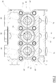
- the volumetric pump 10 comprises an outer casing, commonly called head 20 defining a cylinder 21 with which a reciprocating piston 30 is associated so as to be able to slide in the axial direction.
- the volumetric pump 10 in the example, comprises a plurality (in the example 3 in number) of (identical) cylinders 21, for example parallel and equidistant, with each of which a respective reciprocating piston 30 is associated so as to be able to slide in the axial direction, defining a respective compression chamber 22.
- the volumetric pump 10 comprises an intake manifold 23 and a delivery manifold 24, both of which can be made in the head 20.
- Each compression chamber 22 can be connected to the intake manifold 23 through a respective intake pipe 25, for example through a respective intake valve 26.
- the intake manifold 23 opens outside of the head 20 through an inlet opening (not illustrated) and, together with each intake pipe 25 defines (the end segment distal from the compression chamber 22 of) an intake conduit of the volumetric pump 10.
- each compression chamber 22 can be connected to the delivery manifold 24 through a respective delivery pipe 27, for example through a respective delivery valve 28.
- the delivery manifold 24 opens outside of the head 20 through an outlet opening (not illustrated) and, together with each delivery pipe 27 defines (the end segment distal from the compression chamber 22 of) a delivery conduit of the volumetric pump 10.
- the intake valves 26 and the delivery valves 28 can be automatic one-way valves and are per se conventional.
- the inlet opening of the intake conduit i.e. of the intake manifold 23
- the outlet opening of the delivery conduit i.e. of the delivery manifold 24
- a dispensing device for example to a dispensing gun or rod, which can be equipped with suitable valve members adapted for selectively opening and closing the dispensing of the fluid following a manual actuation.
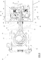
- Each reciprocating piston 30 comprises a cylindrical jacket 31, typically made of ceramic material, which is coaxially slotted onto a support stem 32, typically made of metallic material like steel.
- the support stem 32 is coaxially formed in a single body with a rear cylindrical trunk 33 of increased diameter, from which it is separated by a shoulder 34.
- the cylindrical jacket 31 is axially locked between the shoulder 34 and a lock nut 35 screwed to the free end of the support stem 32.
- the rear trunk 33 is localized outside of the head 20 and is arranged inside a case 50 fixed to the head 20 itself, for example slidably slotted inside a cylindrical guide seat 51 formed in the case 50.
- the case 50 houses a crankshaft 52 and a connecting rod 53, which is articulated both to the rear trunk 33 and to the crankshaft 52, so as to make a thrusting crank gear (of the rod-crank type) adapted for transforming the rotary motion of the crankshaft 52 into a reciprocating movement of the reciprocating piston 30 along the direction defined by its own longitudinal axis A.
- the rotation of the crankshaft 52 is actuated by a motor (not illustrated) arranged outside of the case 50.
- a lip annular gasket 54 is coaxially interposed between the rear trunk 33 and the cylindrical guide seat 51, fixedly connected to the latter, so as to hold the lubricant oil for the joints of the connecting rod 53 with the crankshaft 52 and the rear trunk 33 inside the case 50.
- each compression chamber 22 is entrusted to respective two annular gaskets that are fixed to the head 20, for example inside the cylinder 21 and that are coaxially slotted onto the cylindrical jacket 31 of the reciprocating piston 30.
- each compression chamber 22 is delimited by a first annular gasket 60, called high-pressure gasket, which is directly subjected to the pressure of the compression chamber 22 and is coaxially inserted in a suitable annular seat formed in the respective cylinder 21, and a second annular gasket 61, called low-pressure gasket, which is also coaxially inserted in a suitable annular seat formed in the respective cylinder 21 and is arranged a greater distance from the top of the reciprocating piston 30 with respect to the first gasket 60.
- first annular gasket 60 called high-pressure gasket
- low-pressure gasket which is also coaxially inserted in a suitable annular seat formed in the respective cylinder 21 and is arranged a greater distance from the top of the reciprocating piston 30 with respect to the first gasket 60.
- the first gasket 60 has the purpose of holding the fluid to be pumped inside the compression chamber 22, whereas a purpose of the second gasket 61 is that of holding the fluid losses that can sometimes get past the first gasket 60, preventing them from being able to leak into the case 50 and, at the same time allowing the recovery thereof (as will be described more clearly hereinafter).
- the first gasket 60 is a gasket of more rigid material (for example a bi-component material made from rubber and cloth) with respect to the material that constitutes the second gasket 61 (for example a single-component material made of only rubber).
- each cylinder 21 an enlarged receiving seat is defined, formed in the head and distal from the top of the respective reciprocating piston 30, which is coaxial to the cylinder 21 itself and defines the opening thereof through which the reciprocating piston 30 penetrates into the compression chamber 22.
- the first gasket 60 is housed inside the receiving seat and is axially locked between a support ring 62, for example fixed by interference inside the receiving seat itself, and a shoulder that separates the receiving seat from the compression chamber 22.
- the support ring 62 also has an inner radial opening in which the second gasket 61 is received, so that it can project radially towards the cylindrical jacket 31 of the reciprocating piston 30.
- the support ring 62 has a plurality of radial grooves of full extension, i.e. passing from one side to the other thereof, which, for example, are connected with the radial opening in which the second gasket 61 is received through a radial constriction.
- a further annular gasket in this case a sealing O-ring, can be coaxially interposed between the support ring 62 and the receiving seat, for example at or close to the end thereof distal from the top of the reciprocating piston 30.
- a gap is defined that defines a collection chamber 65, for example substantially of annular or toroidal shape, which is intended to receive the losses of fluid that can sometimes get past the first gasket 60.
- the collection chamber 65 is defined by the radial grooves and by the radial construction of the support ring 62 (and by the cylindrical jacket 31 of the reciprocating piston 30).
- This collection chamber 65 is separated from the compression chamber 22 through the first gasket 60; it is separated from the external environment through the aforementioned further annular gasket and it is separated from the internal environment of the case 50 through the second gasket 61.
- the volumetric pump 10 also comprises a recirculation conduit 70 which places the collection chamber 65 in fluid communication with the intake conduit, in particular in the example the intake manifold 23, upstream of the intake valve 26 in the crossing direction of the fluid from the inlet opening to the compression chamber 22.
- each collection chamber 65 is connected to the intake conduit, in particular to the intake manifold 23, through a respective recirculation conduit 70.
- Each recirculation conduit 70 is for example made in the head 20, for example by milling, and has a first end that opens into the collection chamber 65 and an opposite second end that opens into the intake conduit, i.e. into the intake manifold 23.
- the fluid that from the compression chamber 22 leaks through the first gasket 60 is collected in the collection chamber 65 and from here it can be recovered at the intake of the volumetric pump 10, i.e. reintroduced into the intake manifold 23, through the recirculation conduit 70.
- the volumetric pump 10 comprises a lubrication conduit 80 which places the delivery conduit, in particular in the example the delivery manifold 24, preferably downstream of the delivery valve 28 in the crossing direction of the fluid from the compression chamber 22 to the outlet opening, in fluid communication with the collection chamber 65.
- the lubrication conduit 80 is made in the head 20, for example by milling, and has a first end that opens into the collection chamber 65 and an opposite second end that opens into the delivery conduit, i.e. into the delivery manifold 24.
- the first end of the lubrication conduit 80 that opens into the collection chamber 65 is substantially diametrically opposite to the first end of the recirculation conduit that opens into the same collection chamber 65.
- the lubrication conduit 80 has an axial segment, for example proximal to the second end, which has an internal threading.
- the volumetric pump 10 comprises a nozzle 81, for example a nebulizing nozzle, which is arranged inside the lubrication conduit 80, for example screwed to the internal threading thereof.
- the nozzle 81 comprises an axially passing inner channel, for example having a calibrated minimum diameter, for example of 0.1 mm, which allows the nebulization of the fluid that crosses it.
- the inner channel has a minimum diameter at the axial end of the nozzle 81 itself proximal to the second end of the lubrication conduit 80 (the inner channel also has sections with increasing diameter up to the opposite axial end thereof).
- the lubrication conduit 80 can itself constitute a nozzle (nebulizer) or have a (minimum) inner diameter such as to allow the nebulization of the fluid that crosses it.
- a minimal part of the (high-pressure) fluid that is sent from the compression chamber 22 to the delivery conduit, preferably to the delivery manifold 24, can be tapped through the lubrication conduit 80 and, thus, through the nozzle 81, and be sent - thus nebulized - in the collection chamber 65.
- the pressurised nebulized fluid that is introduced through the lubrication conduit 80 into the collection chamber 65 exerts a thrust that pushes possible accumulations of residual air that would otherwise accumulate in the collection chamber 65 itself and that would cause cavitation and, therefore, the deterioration of the cylindrical jacket 31 of the reciprocating piston 30 jeopardising the seal of the first gasket 60 and of the second gasket 61 themselves outside of the collection chamber 65, through the recirculation conduit 70.
- the volumetric pump 10 comprises a plurality of lubrication conduits 80, in particular a lubrication conduit 80 (with respective nozzle 81) for each compression chamber 22 (and each collection chamber 65).
- each collection chamber 65 is connected to the delivery conduit, in particular to the delivery manifold 24, through a respective lubrication conduit 80 possibly equipped with a respective nozzle 81.
- the volumetric pump 10 has a single lubrication conduit 80, preferably with a respective nozzle 81, said single lubrication conduit 80 connecting the delivery conduit, i.e. the delivery manifold 24, with a single collection chamber 65, for example a central collection chamber 65 of the volumetric pump 10.
- the collection chamber 65 that is connected to the lubrication conduit 80, as described above, is connected to the other collection chambers 65 through a respective service channel 90, for example radial.
- Each service channel can be a through hole or a milling (enlarged) that connects a collection chamber 65 (peripheral) with the collection chamber 65 (central) into which (the first end of) the lubrication conduit 80 opens.
- the volumetric pump itself has a single lubrication conduit 80, but a plurality of recirculation conduits 70 (one for each collection chamber 65).
- the volumetric pump 10 does not rule out the possibility that in such a second embodiment it is possible to provide for the volumetric pump 10 to also be able to have a single recirculation conduit 70 that connects the intake conduit, i.e. the intake manifold 23, with a single collection chamber 65, for example the central collection chamber 65 of the volumetric pump 10 or a different collection chamber 65 (for example peripheral).
- the volumetric pump 10 has a plurality of recirculation conduits 70, one for each collection chamber 65 (peripheral) into which the lubrication conduit 80 does not open.
- each collection chamber 65 is always hit by a flow of fluid (calibrated and nebulized through the nozzle 81, i.e. the minimum passage section thereof) that, entering from the lubrication conduit 80, crosses it in the circumferential direction to then come out from the recirculation conduit 70.
- Such a flow of fluid (nebulized and continuous), as stated above, always contains a certain amount of fluid coming from the intake of the pump 10, which is held inside the gap also thanks to the second gasket 61, and promotes the cooling and the lubrication of the second gasket 61 (i.e. the low-pressure gasket) and, at the same time, allows the collection chamber to be washed of possible accumulations or residual air pockets that would otherwise accumulate in the collection chamber 65 itself.
Landscapes
- Engineering & Computer Science (AREA)
- Mechanical Engineering (AREA)
- General Engineering & Computer Science (AREA)
- Details Of Reciprocating Pumps (AREA)
- Compressor (AREA)
- Toys (AREA)
Claims (8)
- Volumetrische Kolbenpumpe (10), die umfasst:- ein Gehäuse (20), mit einem Zylinder (21) ausgerüstet, der einen Kompressionsraum (22) umgrenzt, welcher mit einer Ansaugleitung (23, 25) und einer Förderleitung (24, 27) kommuniziert;- ein Hubkolben (30) der im Zylinder (21) gleitet und den Kompressionsraum (22) begrenzt;- eine erste Dichtung (60), die an dem Gehäuse (20) im Zylinder (21) angebracht und koaxial in den Hubkolben (30) eingesetzt ist;- eine zweite Dichtung (61), die an dem Gehäuse (20) im Zylinder (21) angebracht ist und koaxial in den Hubkolben (30) entfernt vom Kompressionsraum (22) in Bezug auf die erste Dichtung (60) eingesetzt ist;- ein Sammelraum (65), der zwischen der ersten Dichtung (60) und der zweiten Dichtung (61) eingefügt und axial begrenzt ist;- ein Zirkulationskanal (70), der den Sammelraum (65) mit der Ansaugleitung (23, 25) verbindet;dadurch charakterisiert, dass die volumetrische Kolbenpumpe (10) ferner umfasst:- eine Schmiermittelleitung (80), die die Förderleitung (24, 27) mit dem Sammelraum (65) verbindet;
- Volumetrische Kolbenpumpe (10) gemäß Anspruch 1, die eine Düse (81) umfasst, welche sich in der Schmiermittelleitung (80) befindet.
- Volumetrische Kolbenpumpe (10) gemäß Anspruch 1, bei der die Schmiermittelleitung (80) im Gehäuse (20) eingebaut ist.
- Volumetrische Kolbenpumpe (10) gemäß Anspruch 1, bei der das Gehäuse (20) eine Vielzahl von Zylindern (21), in denen ein entsprechender Hubkolben (30) untergebracht ist, sowie eine entsprechende Vielzahl von Sammelräumen (65) umfasst.
- Volumetrische Kolbenpumpe (10) gemäß Anspruch 4, die eine Schmiermittelleitung (80) für jeden Sammelraum (65) jedes Zylinders (21) umfasst.
- Volumetrische Kolbenpumpe (10) gemäß Anspruch 4, die eine einzelne Schmiermittelleitung (80) umfasst, welche die Förderleitung (24, 27) mit einem einzelnen Sammelraum (65) aus der Vielzahl von Sammelräumen (65) verbindet, wobei der mit der Schmiermittelleitung (80) verbundenen Sammelraum (65) mit den anderen Sammelräumen (65) über einen entsprechenden Servicekanal (90) verbunden ist.
- Volumetrische Kolbenpumpe (10) gemäß Anspruch 1, bei der in der Ansaugleitung (23, 25) ein Einweg-Ansaugventil (26) installiert ist.
- Volumetrische Kolbenpumpe (10) gemäß Anspruch 1, bei der in der Förderleitung (24, 27) ein Einweg-Förderventil (28) installiert ist.
Applications Claiming Priority (1)
| Application Number | Priority Date | Filing Date | Title |
|---|---|---|---|
| IT102018000006145A IT201800006145A1 (it) | 2018-06-08 | 2018-06-08 | Pompa volumetrica a pistoni |
Publications (2)
| Publication Number | Publication Date |
|---|---|
| EP3578811A1 EP3578811A1 (de) | 2019-12-11 |
| EP3578811B1 true EP3578811B1 (de) | 2021-03-17 |
Family
ID=63449591
Family Applications (1)
| Application Number | Title | Priority Date | Filing Date |
|---|---|---|---|
| EP19174328.5A Active EP3578811B1 (de) | 2018-06-08 | 2019-05-14 | Volumetrische kolbenpumpe |
Country Status (3)
| Country | Link |
|---|---|
| EP (1) | EP3578811B1 (de) |
| DK (1) | DK3578811T3 (de) |
| IT (1) | IT201800006145A1 (de) |
Families Citing this family (2)
| Publication number | Priority date | Publication date | Assignee | Title |
|---|---|---|---|---|
| IT202100006824A1 (it) * | 2021-03-22 | 2022-09-22 | Annovi Reverberi Spa | Pompa volumetrica a pistoni ad alta pressione |
| CN116060253A (zh) * | 2021-11-03 | 2023-05-05 | 苏州泽森电子科技有限公司 | 一种灌胶一体机 |
Family Cites Families (6)
| Publication number | Priority date | Publication date | Assignee | Title |
|---|---|---|---|---|
| US5415531A (en) * | 1994-04-06 | 1995-05-16 | Binks Manufacturing Company | Piston pump for fluent materials |
| DE10239943C1 (de) * | 2002-08-30 | 2003-10-30 | Kaercher Gmbh & Co Kg Alfred | Pumpe für ein Hochdruckreinigungsgerät |
| EP2025937B1 (de) * | 2007-08-07 | 2010-06-23 | Three Es S.r.l. | Kolbenpumpe |
| JP5210261B2 (ja) * | 2008-07-30 | 2013-06-12 | 株式会社丸山製作所 | 往復動ポンプ |
| US8308450B2 (en) * | 2009-03-05 | 2012-11-13 | Cummins Intellectual Properties, Inc. | High pressure fuel pump with parallel cooling fuel flow |
| ITRE20120078A1 (it) * | 2012-11-02 | 2014-05-03 | Interpump Engineering Srl | Pompa idraulica a pistoni |
-
2018
- 2018-06-08 IT IT102018000006145A patent/IT201800006145A1/it unknown
-
2019
- 2019-05-14 DK DK19174328.5T patent/DK3578811T3/da active
- 2019-05-14 EP EP19174328.5A patent/EP3578811B1/de active Active
Non-Patent Citations (1)
| Title |
|---|
| None * |
Also Published As
| Publication number | Publication date |
|---|---|
| IT201800006145A1 (it) | 2019-12-08 |
| EP3578811A1 (de) | 2019-12-11 |
| DK3578811T3 (da) | 2021-06-07 |
Similar Documents
| Publication | Publication Date | Title |
|---|---|---|
| EP2860396B1 (de) | Pumpe | |
| US8366409B2 (en) | Reciprocating pump | |
| US9394900B2 (en) | Internal bellows pump fluid path | |
| US10190553B2 (en) | Pumping unit for feeding fuel, preferably diesel fuel, from a storage tank to an internal combustion engine | |
| WO2017096488A1 (en) | Fluid end assembly of a reciprocating pump | |
| CN106930938A (zh) | 用于泵的有凹槽的活塞部件 | |
| EP3578811B1 (de) | Volumetrische kolbenpumpe | |
| US4874297A (en) | Radial pump | |
| EP4063653B1 (de) | Volumetrische hochdruck-kolbenpumpe | |
| CN110345371A (zh) | 自润滑泵的喉部密封件 | |
| US7661935B2 (en) | High pressure pump | |
| EP2466138A1 (de) | Pumpe mit Kolbenführung | |
| EP3557059B1 (de) | Volumetrische membranpumpe | |
| KR20020090198A (ko) | 피스톤 왕복식 고압분무기에서 피스톤의 윤활장치 | |
| RU2739103C1 (ru) | Насос буровой трехпоршневой одностороннего действия | |
| RU68084U1 (ru) | Механическое уплотнение плунжерного насоса | |
| KR102216489B1 (ko) | 내연 피스톤 기관에 연료를 공급하기 위한 연료 펌프 | |
| CN104912792B (zh) | 机械驱动活塞作用于流体的对夹摇摆托盘活塞摇摆驱动机 | |
| WO2013141737A1 (ru) | Двигатель внутреннего сгорания | |
| US20120042773A1 (en) | Pump Piston Device | |
| EP3601778B1 (de) | Kraftstoffpumpe für eine verbrennungskraftmaschine | |
| KR200302261Y1 (ko) | 피스톤 왕복식 고압분무기에서 피스톤의 윤활장치 | |
| CN120175632A (zh) | 用于泵的阀组件 | |
| JP2652379B2 (ja) | 可変容量式往復ポンプ | |
| WO2021260408A1 (en) | Head for a volumetric pump |
Legal Events
| Date | Code | Title | Description |
|---|---|---|---|
| PUAI | Public reference made under article 153(3) epc to a published international application that has entered the european phase |
Free format text: ORIGINAL CODE: 0009012 |
|
| STAA | Information on the status of an ep patent application or granted ep patent |
Free format text: STATUS: THE APPLICATION HAS BEEN PUBLISHED |
|
| AK | Designated contracting states |
Kind code of ref document: A1 Designated state(s): AL AT BE BG CH CY CZ DE DK EE ES FI FR GB GR HR HU IE IS IT LI LT LU LV MC MK MT NL NO PL PT RO RS SE SI SK SM TR |
|
| AX | Request for extension of the european patent |
Extension state: BA ME |
|
| STAA | Information on the status of an ep patent application or granted ep patent |
Free format text: STATUS: REQUEST FOR EXAMINATION WAS MADE |
|
| 17P | Request for examination filed |
Effective date: 20200608 |
|
| RBV | Designated contracting states (corrected) |
Designated state(s): AL AT BE BG CH CY CZ DE DK EE ES FI FR GB GR HR HU IE IS IT LI LT LU LV MC MK MT NL NO PL PT RO RS SE SI SK SM TR |
|
| REG | Reference to a national code |
Ref country code: DE Ref legal event code: R079 Ref document number: 602019003186 Country of ref document: DE Free format text: PREVIOUS MAIN CLASS: F04B0001040000 Ipc: F04B0001044300 |
|
| GRAP | Despatch of communication of intention to grant a patent |
Free format text: ORIGINAL CODE: EPIDOSNIGR1 |
|
| STAA | Information on the status of an ep patent application or granted ep patent |
Free format text: STATUS: GRANT OF PATENT IS INTENDED |
|
| RIC1 | Information provided on ipc code assigned before grant |
Ipc: F04B 53/18 20060101ALI20200921BHEP Ipc: F04B 53/04 20060101ALI20200921BHEP Ipc: F04B 53/16 20060101ALI20200921BHEP Ipc: F04B 1/0443 20200101AFI20200921BHEP Ipc: F04B 39/12 20060101ALN20200921BHEP |
|
| INTG | Intention to grant announced |
Effective date: 20201020 |
|
| GRAS | Grant fee paid |
Free format text: ORIGINAL CODE: EPIDOSNIGR3 |
|
| GRAA | (expected) grant |
Free format text: ORIGINAL CODE: 0009210 |
|
| STAA | Information on the status of an ep patent application or granted ep patent |
Free format text: STATUS: THE PATENT HAS BEEN GRANTED |
|
| AK | Designated contracting states |
Kind code of ref document: B1 Designated state(s): AL AT BE BG CH CY CZ DE DK EE ES FI FR GB GR HR HU IE IS IT LI LT LU LV MC MK MT NL NO PL PT RO RS SE SI SK SM TR |
|
| REG | Reference to a national code |
Ref country code: GB Ref legal event code: FG4D |
|
| REG | Reference to a national code |
Ref country code: CH Ref legal event code: EP |
|
| REG | Reference to a national code |
Ref country code: DE Ref legal event code: R096 Ref document number: 602019003186 Country of ref document: DE |
|
| REG | Reference to a national code |
Ref country code: IE Ref legal event code: FG4D |
|
| REG | Reference to a national code |
Ref country code: AT Ref legal event code: REF Ref document number: 1372477 Country of ref document: AT Kind code of ref document: T Effective date: 20210415 |
|
| REG | Reference to a national code |
Ref country code: DK Ref legal event code: T3 Effective date: 20210603 |
|
| REG | Reference to a national code |
Ref country code: LT Ref legal event code: MG9D |
|
| PG25 | Lapsed in a contracting state [announced via postgrant information from national office to epo] |
Ref country code: NO Free format text: LAPSE BECAUSE OF FAILURE TO SUBMIT A TRANSLATION OF THE DESCRIPTION OR TO PAY THE FEE WITHIN THE PRESCRIBED TIME-LIMIT Effective date: 20210617 Ref country code: HR Free format text: LAPSE BECAUSE OF FAILURE TO SUBMIT A TRANSLATION OF THE DESCRIPTION OR TO PAY THE FEE WITHIN THE PRESCRIBED TIME-LIMIT Effective date: 20210317 Ref country code: GR Free format text: LAPSE BECAUSE OF FAILURE TO SUBMIT A TRANSLATION OF THE DESCRIPTION OR TO PAY THE FEE WITHIN THE PRESCRIBED TIME-LIMIT Effective date: 20210618 Ref country code: FI Free format text: LAPSE BECAUSE OF FAILURE TO SUBMIT A TRANSLATION OF THE DESCRIPTION OR TO PAY THE FEE WITHIN THE PRESCRIBED TIME-LIMIT Effective date: 20210317 Ref country code: BG Free format text: LAPSE BECAUSE OF FAILURE TO SUBMIT A TRANSLATION OF THE DESCRIPTION OR TO PAY THE FEE WITHIN THE PRESCRIBED TIME-LIMIT Effective date: 20210617 |
|
| REG | Reference to a national code |
Ref country code: AT Ref legal event code: MK05 Ref document number: 1372477 Country of ref document: AT Kind code of ref document: T Effective date: 20210317 |
|
| REG | Reference to a national code |
Ref country code: NL Ref legal event code: MP Effective date: 20210317 |
|
| PG25 | Lapsed in a contracting state [announced via postgrant information from national office to epo] |
Ref country code: RS Free format text: LAPSE BECAUSE OF FAILURE TO SUBMIT A TRANSLATION OF THE DESCRIPTION OR TO PAY THE FEE WITHIN THE PRESCRIBED TIME-LIMIT Effective date: 20210317 Ref country code: LV Free format text: LAPSE BECAUSE OF FAILURE TO SUBMIT A TRANSLATION OF THE DESCRIPTION OR TO PAY THE FEE WITHIN THE PRESCRIBED TIME-LIMIT Effective date: 20210317 Ref country code: SE Free format text: LAPSE BECAUSE OF FAILURE TO SUBMIT A TRANSLATION OF THE DESCRIPTION OR TO PAY THE FEE WITHIN THE PRESCRIBED TIME-LIMIT Effective date: 20210317 |
|
| PG25 | Lapsed in a contracting state [announced via postgrant information from national office to epo] |
Ref country code: NL Free format text: LAPSE BECAUSE OF FAILURE TO SUBMIT A TRANSLATION OF THE DESCRIPTION OR TO PAY THE FEE WITHIN THE PRESCRIBED TIME-LIMIT Effective date: 20210317 |
|
| PG25 | Lapsed in a contracting state [announced via postgrant information from national office to epo] |
Ref country code: CZ Free format text: LAPSE BECAUSE OF FAILURE TO SUBMIT A TRANSLATION OF THE DESCRIPTION OR TO PAY THE FEE WITHIN THE PRESCRIBED TIME-LIMIT Effective date: 20210317 Ref country code: EE Free format text: LAPSE BECAUSE OF FAILURE TO SUBMIT A TRANSLATION OF THE DESCRIPTION OR TO PAY THE FEE WITHIN THE PRESCRIBED TIME-LIMIT Effective date: 20210317 Ref country code: LT Free format text: LAPSE BECAUSE OF FAILURE TO SUBMIT A TRANSLATION OF THE DESCRIPTION OR TO PAY THE FEE WITHIN THE PRESCRIBED TIME-LIMIT Effective date: 20210317 Ref country code: SM Free format text: LAPSE BECAUSE OF FAILURE TO SUBMIT A TRANSLATION OF THE DESCRIPTION OR TO PAY THE FEE WITHIN THE PRESCRIBED TIME-LIMIT Effective date: 20210317 Ref country code: AT Free format text: LAPSE BECAUSE OF FAILURE TO SUBMIT A TRANSLATION OF THE DESCRIPTION OR TO PAY THE FEE WITHIN THE PRESCRIBED TIME-LIMIT Effective date: 20210317 |
|
| PG25 | Lapsed in a contracting state [announced via postgrant information from national office to epo] |
Ref country code: PL Free format text: LAPSE BECAUSE OF FAILURE TO SUBMIT A TRANSLATION OF THE DESCRIPTION OR TO PAY THE FEE WITHIN THE PRESCRIBED TIME-LIMIT Effective date: 20210317 Ref country code: RO Free format text: LAPSE BECAUSE OF FAILURE TO SUBMIT A TRANSLATION OF THE DESCRIPTION OR TO PAY THE FEE WITHIN THE PRESCRIBED TIME-LIMIT Effective date: 20210317 Ref country code: PT Free format text: LAPSE BECAUSE OF FAILURE TO SUBMIT A TRANSLATION OF THE DESCRIPTION OR TO PAY THE FEE WITHIN THE PRESCRIBED TIME-LIMIT Effective date: 20210719 Ref country code: SK Free format text: LAPSE BECAUSE OF FAILURE TO SUBMIT A TRANSLATION OF THE DESCRIPTION OR TO PAY THE FEE WITHIN THE PRESCRIBED TIME-LIMIT Effective date: 20210317 Ref country code: IS Free format text: LAPSE BECAUSE OF FAILURE TO SUBMIT A TRANSLATION OF THE DESCRIPTION OR TO PAY THE FEE WITHIN THE PRESCRIBED TIME-LIMIT Effective date: 20210717 |
|
| REG | Reference to a national code |
Ref country code: DE Ref legal event code: R097 Ref document number: 602019003186 Country of ref document: DE |
|
| PLBE | No opposition filed within time limit |
Free format text: ORIGINAL CODE: 0009261 |
|
| STAA | Information on the status of an ep patent application or granted ep patent |
Free format text: STATUS: NO OPPOSITION FILED WITHIN TIME LIMIT |
|
| PG25 | Lapsed in a contracting state [announced via postgrant information from national office to epo] |
Ref country code: MC Free format text: LAPSE BECAUSE OF FAILURE TO SUBMIT A TRANSLATION OF THE DESCRIPTION OR TO PAY THE FEE WITHIN THE PRESCRIBED TIME-LIMIT Effective date: 20210317 Ref country code: LU Free format text: LAPSE BECAUSE OF NON-PAYMENT OF DUE FEES Effective date: 20210514 Ref country code: AL Free format text: LAPSE BECAUSE OF FAILURE TO SUBMIT A TRANSLATION OF THE DESCRIPTION OR TO PAY THE FEE WITHIN THE PRESCRIBED TIME-LIMIT Effective date: 20210317 Ref country code: ES Free format text: LAPSE BECAUSE OF FAILURE TO SUBMIT A TRANSLATION OF THE DESCRIPTION OR TO PAY THE FEE WITHIN THE PRESCRIBED TIME-LIMIT Effective date: 20210317 |
|
| REG | Reference to a national code |
Ref country code: BE Ref legal event code: MM Effective date: 20210531 |
|
| 26N | No opposition filed |
Effective date: 20211220 |
|
| PG25 | Lapsed in a contracting state [announced via postgrant information from national office to epo] |
Ref country code: SI Free format text: LAPSE BECAUSE OF FAILURE TO SUBMIT A TRANSLATION OF THE DESCRIPTION OR TO PAY THE FEE WITHIN THE PRESCRIBED TIME-LIMIT Effective date: 20210317 |
|
| PG25 | Lapsed in a contracting state [announced via postgrant information from national office to epo] |
Ref country code: IE Free format text: LAPSE BECAUSE OF NON-PAYMENT OF DUE FEES Effective date: 20210514 |
|
| PG25 | Lapsed in a contracting state [announced via postgrant information from national office to epo] |
Ref country code: IS Free format text: LAPSE BECAUSE OF FAILURE TO SUBMIT A TRANSLATION OF THE DESCRIPTION OR TO PAY THE FEE WITHIN THE PRESCRIBED TIME-LIMIT Effective date: 20210717 Ref country code: FR Free format text: LAPSE BECAUSE OF NON-PAYMENT OF DUE FEES Effective date: 20210517 |
|
| PG25 | Lapsed in a contracting state [announced via postgrant information from national office to epo] |
Ref country code: BE Free format text: LAPSE BECAUSE OF NON-PAYMENT OF DUE FEES Effective date: 20210531 |
|
| REG | Reference to a national code |
Ref country code: CH Ref legal event code: PL |
|
| PG25 | Lapsed in a contracting state [announced via postgrant information from national office to epo] |
Ref country code: LI Free format text: LAPSE BECAUSE OF NON-PAYMENT OF DUE FEES Effective date: 20220531 Ref country code: CH Free format text: LAPSE BECAUSE OF NON-PAYMENT OF DUE FEES Effective date: 20220531 |
|
| P01 | Opt-out of the competence of the unified patent court (upc) registered |
Effective date: 20230513 |
|
| PG25 | Lapsed in a contracting state [announced via postgrant information from national office to epo] |
Ref country code: CY Free format text: LAPSE BECAUSE OF FAILURE TO SUBMIT A TRANSLATION OF THE DESCRIPTION OR TO PAY THE FEE WITHIN THE PRESCRIBED TIME-LIMIT Effective date: 20210317 |
|
| PG25 | Lapsed in a contracting state [announced via postgrant information from national office to epo] |
Ref country code: HU Free format text: LAPSE BECAUSE OF FAILURE TO SUBMIT A TRANSLATION OF THE DESCRIPTION OR TO PAY THE FEE WITHIN THE PRESCRIBED TIME-LIMIT; INVALID AB INITIO Effective date: 20190514 |
|
| GBPC | Gb: european patent ceased through non-payment of renewal fee |
Effective date: 20230514 |
|
| PG25 | Lapsed in a contracting state [announced via postgrant information from national office to epo] |
Ref country code: MK Free format text: LAPSE BECAUSE OF FAILURE TO SUBMIT A TRANSLATION OF THE DESCRIPTION OR TO PAY THE FEE WITHIN THE PRESCRIBED TIME-LIMIT Effective date: 20210317 Ref country code: GB Free format text: LAPSE BECAUSE OF NON-PAYMENT OF DUE FEES Effective date: 20230514 |
|
| PG25 | Lapsed in a contracting state [announced via postgrant information from national office to epo] |
Ref country code: MT Free format text: LAPSE BECAUSE OF FAILURE TO SUBMIT A TRANSLATION OF THE DESCRIPTION OR TO PAY THE FEE WITHIN THE PRESCRIBED TIME-LIMIT Effective date: 20210317 |
|
| PGFP | Annual fee paid to national office [announced via postgrant information from national office to epo] |
Ref country code: DE Payment date: 20250529 Year of fee payment: 7 |
|
| PGFP | Annual fee paid to national office [announced via postgrant information from national office to epo] |
Ref country code: DK Payment date: 20250526 Year of fee payment: 7 |
|
| PG25 | Lapsed in a contracting state [announced via postgrant information from national office to epo] |
Ref country code: TR Free format text: LAPSE BECAUSE OF FAILURE TO SUBMIT A TRANSLATION OF THE DESCRIPTION OR TO PAY THE FEE WITHIN THE PRESCRIBED TIME-LIMIT Effective date: 20210317 |
|
| PGFP | Annual fee paid to national office [announced via postgrant information from national office to epo] |
Ref country code: IT Payment date: 20260224 Year of fee payment: 8 |