EP3579584B1 - Commande de rendu d'une scène audio spatiale - Google Patents
Commande de rendu d'une scène audio spatiale Download PDFInfo
- Publication number
- EP3579584B1 EP3579584B1 EP18176444.0A EP18176444A EP3579584B1 EP 3579584 B1 EP3579584 B1 EP 3579584B1 EP 18176444 A EP18176444 A EP 18176444A EP 3579584 B1 EP3579584 B1 EP 3579584B1
- Authority
- EP
- European Patent Office
- Prior art keywords
- sub
- audio output
- output channels
- sound
- user
- Prior art date
- Legal status (The legal status is an assumption and is not a legal conclusion. Google has not performed a legal analysis and makes no representation as to the accuracy of the status listed.)
- Active
Links
Images


Classifications
-
- H—ELECTRICITY
- H04—ELECTRIC COMMUNICATION TECHNIQUE
- H04S—STEREOPHONIC SYSTEMS
- H04S7/00—Indicating arrangements; Control arrangements, e.g. balance control
- H04S7/30—Control circuits for electronic adaptation of the sound field
- H04S7/302—Electronic adaptation of stereophonic sound system to listener position or orientation
- H04S7/303—Tracking of listener position or orientation
-
- H—ELECTRICITY
- H04—ELECTRIC COMMUNICATION TECHNIQUE
- H04S—STEREOPHONIC SYSTEMS
- H04S7/00—Indicating arrangements; Control arrangements, e.g. balance control
- H04S7/30—Control circuits for electronic adaptation of the sound field
- H04S7/302—Electronic adaptation of stereophonic sound system to listener position or orientation
-
- H—ELECTRICITY
- H04—ELECTRIC COMMUNICATION TECHNIQUE
- H04S—STEREOPHONIC SYSTEMS
- H04S3/00—Systems employing more than two channels, e.g. quadraphonic
- H04S3/008—Systems employing more than two channels, e.g. quadraphonic in which the audio signals are in digital form, i.e. employing more than two discrete digital channels
-
- H—ELECTRICITY
- H04—ELECTRIC COMMUNICATION TECHNIQUE
- H04R—LOUDSPEAKERS, MICROPHONES, GRAMOPHONE PICK-UPS OR LIKE ACOUSTIC ELECTROMECHANICAL TRANSDUCERS; ELECTRIC HEARING AIDS; PUBLIC ADDRESS SYSTEMS
- H04R2460/00—Details of hearing devices, i.e. of ear- or headphones covered by H04R1/10 or H04R5/033 but not provided for in any of their subgroups, or of hearing aids covered by H04R25/00 but not provided for in any of its subgroups
- H04R2460/07—Use of position data from wide-area or local-area positioning systems in hearing devices, e.g. program or information selection
Definitions
- Embodiments of the present disclosure relate to rendering spatial audio scenes in sub-optimal conditions.
- the location or bearing may be a location or bearing in three-dimensional space for volumetric or three-dimensional spatial audio, or a position or direction in a plane for two-dimensional spatial audio.
- a “sound space” refers to the sound field created by an arrangement of sound sources in a space.
- a sound space may be defined in relation to recording sounds (a recorded sound space) and in relation to rendering sounds (a rendered sound space).
- a “sound scene” refers to a representation of the sound space as if listened to from a particular point of view within the sound space.
- a “sound object” refers to a sound source that may be located within the sound space irrespective of how it is encoded. It may for example by located by position or by direction.
- a recorded sound object represents sounds recorded at a particular microphone or from a particular location.
- a rendered sound object represents sounds rendered as if from a particular location.
- the orientation and/or location of the virtual user in the sound space may change with orientation and/or location of the user in a real space.
- Different formats may be used to encode a spatially varying sound field as spatial audio content.
- binaural encoding may be used for rendering a sound scene via headphones
- a specific type of multi-channel encoding may be used for rendering a sound scene via a correspondingly specific configuration of loudspeakers (for example 5.1 surround sound)
- directional encoding may be used for rendering at least one sound source at a defined direction
- positional encoding may be used for rendering at least one sound source at a defined position.
- An output audio signal can be converted from one format to another.
- the output audio signal produced to render a sound scene needs to be matched to the arrangement of multiple loudspeakers used.
- a particular format of spatial audio may require, for rendering, a particular arrangement of multiple loudspeakers or a particular environment or user position.
- the audio output will be sub-optimal in an uncontrolled way.
- US 2017/0374465 discloses an audio system comprising one or more speaker arrays. Sound program content associated with zones is played in a listening area.
- an apparatus comprising means for: obtaining an indication of an orientation of a loudspeaker system, comprising multiple loudspeaker transducers clustered around a first reference position, the first reference position being a reference position in real space; obtaining a variable position (52) of a user (50) in real space (54); mapping the position (52) of the user (50) in real space (54) to a position (22) of the user (20) in a sound space (2), wherein the sound space comprises a plurality of sound sources; allocating the plurality of sound sources to a first sub-set of the plurality of sound sources or a second sub-set of the plurality of sound sources; allocating multiple audio output channels to a first sub-set of the multiple audio output channels or a second sub-set of the multiple audio output channels; and controlling an output audio signal (30), for rendering a sound scene by the loudspeaker system, the sound scene being determined in dependence upon the orientation of the loudspeaker system in real space and the variable position
- the sound sources for direct rendering and the sound sources for indirect rendering are identified based on the position of the user in the sound space.
- an allocation of a plurality of sound sources to either the first sub-set or the second sub-set is dependent upon at least a position of the user in the sound space relative to the plurality of sound sources.
- the available audio paths for the multiple audio output channels are dependent upon at least a position of the user in the sound space relative to the plurality of sound sources.
- the apparatus comprising the apparatus and the loudspeaker system, wherein the first reference position is at most a first distance from the multiple transducers and wherein the first reference position is a second distance from the position of the user in the real space, and wherein the first distance is less than the second distance.
- the multiple transducers clustered around the reference position face outwardly away from the reference position.
- a method comprising: obtaining an indication of an orientation of a loudspeaker system, comprising multiple loudspeaker transducers clustered around a first reference position, the first reference position being a reference position in real space; obtaining a variable position (52) of a user (50) in real space (54); mapping the position (52) of the user (50) in real space (54) to a position (22) of the user (20) in a sound space (2), wherein the sound space comprises a plurality of sound sources; allocating the plurality of sound sources to a first sub-set of the plurality of sound sources or a second sub-set of the plurality of sound sources; allocating multiple audio output channels to a first sub-set of the multiple audio output channels or a second sub-set of the multiple audio output channels; and controlling an output audio signal (30), for rendering a sound scene by the loudspeaker system, the sound scene being determined in dependence upon the orientation of the loudspeaker system in real space and the variable position of
- a computer program that when run on one or more processors causes: obtaining an indication of an orientation of a loudspeaker system, comprising multiple loudspeaker transducers clustered around a first reference position, the first reference position being a reference position in real space; obtaining a variable position (52) of a user (50) in real space (54); mapping the position (52) of the user (50) in real space (54) to a position (22) of the user (20) in a sound space (2), wherein the sound space comprises a plurality of sound sources; allocating the plurality of sound sources to a first sub-set of the plurality of sound sources or a second sub-set of the plurality of sound sources; allocating multiple audio output channels to a first sub-set of the multiple audio output channels or a second sub-set of the multiple audio output channels; and controlling an output audio signal (30), for rendering a sound scene by the loudspeaker system, the sound scene being determined in dependence upon the orientation of the loudspeaker
- an apparatus comprising: at least one processor; and at least one memory including computer program code, the at least one memory and the computer program code configured to, with the at least one processor, cause the apparatus 100 at least to perform: obtaining an indication of an orientation of a loudspeaker system, comprising multiple loudspeaker transducers clustered around a first reference position, the first reference position being a reference position in real space; obtaining a variable position (52) of a user (50) in real space (54); mapping the position (52) of the user (50) in real space (54) to a position (22) of the user (20) in a sound space (2), wherein the sound space comprises a plurality of sound sources; allocating the plurality of sound sources to a first sub-set of the plurality of sound sources or a second sub-set of the plurality of sound sources; allocating multiple audio output channels to a first sub-set of the multiple audio output channels or a second sub-set of the multiple audio output channels; and controlling an output
- an available audio path is a physical path by which an audio signal can reach the at least one user in the real space.
- the allocation can be based on existence of an available audio path or paths and/or based on a length of an available audio path or paths.
- the available audio paths are dependent upon at least a position in the real space of the at least one user.
- a “sound space” refers to the sound field created by an arrangement of sound sources in a space.
- a sound space may be defined in relation to recording sounds (a recorded sound space) and in relation to rendering sounds (a rendered sound space).
- a "sound scene” refers to a representation of the sound space as if listened to from a particular point of view within the sound space.
- a “sound object” refers to sound source that may be located within the sound space irrespective of how it is encoded. It may for example be located by position or by direction.
- a recorded sound object represents sounds recorded at a particular microphone or from a particular location.
- a rendered sound object represents sounds rendered as if from a particular location.
- An indication of a position is the position or some information that indicates the position.
- a position in real space is a location in two or three dimensions in the real world.
- a user is an animal, for example a person, using the system or apparatus. They are the listener to the loudspeaker(s).
- An audio output signal is a signal that can control rendering at a loudspeaker(s).
- the location or bearing may be a location or bearing in three-dimensional space for volumetric or three-dimensional spatial audio, or a location or bearing in a plane for two-dimensional spatial audio.
- a sound space is an arrangement of sound sources in a space that creates a sound field.
- a sound space may, for example, be defined in relation to recording sounds (a recorded sound space) and in relation to rendering sounds (a rendered sound space).
- An audio scene is a representation of the sound space as if listened to from a particular point of view within the sound space.
- a point of view is determined by an orientation of a virtual user and also possibly a location of a virtual user.
- a sound object is a sound source that may be located within the sound space irrespective of how it is encoded. It may for example be positioned by location or by bearing.
- a recorded sound object represents sounds recorded at a particular microphone or location.
- a rendered sound object represents sounds rendered as if from a particular location or bearing.
- Different formats may be used to encode a spatially varying sound field as spatial audio content.
- binaural encoding may be used for rendering an audio scene via headphones
- a specific type of multi-channel encoding may be used for rendering an audio scene via a correspondingly specific configuration of loudspeakers (for example 5.1 or 7.1 surround sound)
- directional encoding may be used for rendering at least one sound source at a defined bearing
- positional encoding may be used for rendering at least one sound source at a defined location.
- An output audio signal used to control rendering can be converted from one format to another.
- the audio output will be sub-optimal in an uncontrolled way.
- a set-up will be sub-optimal, for example, when the audio paths to a user are sub-optimal.
- This may, for example, occur because of a local environment of a user or of a loudspeaker or loudspeakers.
- the user may be at a sub-optimal location and/or orientation for a current arrangement of loudspeakers.
- the arrangement of loudspeakers may be sub-optimal for a location and/or orientation of a user.
- the user may move so that the user or an object obstructs a direct path from a loudspeaker to the user.
- a loudspeaker may fail, be misplaced or be moved so that the intended direct or indirect path to the user is no longer available.
- Some loudspeaker systems for example, have up-ward firing loudspeakers so that sound follows an indirect path, bouncing off a ceiling before reaching a user.
- an optimal arrangement of loudspeakers may not be available and the user may deliberately use a sub-optimal arrangement.
- FIG. 1 illustrates an example of a sound space 2 comprising sound sources 10 and the allocation of sound sources 10 to audio output channels 40.
- the sound space 2 comprises a plurality of sound sources 10.
- a (virtual) user 20 in the sound space 2 has a position 22.
- the FIG. 1 illustrates the allocation of sound sources 10 to audio output channels 40. Sound sources 10 are allocated to sub-sets 12, 14 and then the sub-sets 12, 14 of sound sources 10 are allocated to different sub-sets 42, 44 of audio output channels 40.
- An audio output signal 30 is produced. This audio output signal 30 is for rendering a sound scene via multiple audio channels 40.
- the audio output signal 30 controls rendering of the first sub-set 12 of the sound sources 10 via at least the first sub-set 42 of the multiple audio output channels 40 and rendering the second sub-set 14 of sound sources 10 via at least the second sub-set 44 of the multiple audio output channels 40.
- the audio output signal 30 controls rendering of only the first sub-set 12 of the sound sources 10 via only the first sub-set 42 of the multiple audio output channels 40 and rendering of only the second sub-set 14 of sound sources 10 via only the second sub-set 44 of the multiple audio output channels 40.
- the sound source 10 or an audio output channel 40 can be described as "direct” or “indirect”.
- Direct means that there is a direct primary path to the user.
- the audio appears to the user to arrive from a particular direction and there is little reverberation arising from reflections and multi-path.
- a direct audio path is an audio path in which the audio signal travels directly from the source to the user.
- An indirect audio path is an audio path in which the audio signal travels indirectly from the source to the user. This may, for example, arise or be achieved by having loudspeakers that are at a distance from the user compared to other objects that reflect sound waves, having loudspeakers that do not have a line of sight to the user or having loudspeakers arranged to bounce audio off walls or ceilings to the user.
- the allocation of sub-sets 12, 14 to audio output channels 40 is dependent upon available direct audio paths for the multiple audio output channels.
- a direct path may, for example, be a direct path to the user in real space from a loudspeaker.
- a sound source is indirect, it may be desirable to allocate that sound source 10 to a sub-set 14 of sound objects 10 for indirect sound sources and then allocate that sub-set 14 of indirect sound sources to indirect audio output channels which are a sub-set 44 of the audio output channels 40.
- the first sub-set 12 of sound sources 10 is for direct rendering and the second sub-set 14 of sound sources 10 is for indirect rendering.
- the first sub-set 12 of sound sources 10 is non-overlapping with the second sub-set 12 of sound sources 10.
- a sound source 10 may be allocated to either of first sub-set 12 or the second set 14 of sound sources 10.
- the allocation of sound sources 10 to the sub-sets 12, 14 is dependent upon a position of the user 20 in the sound space 2 relative to a second reference position the second reference position being a reference position in the sound space.
- the second reference position may, for example, be a position in the sound space 2 that corresponds to a position of a or a cluster of loudspeaker transducers 60 in the real space 54.
- a first vector between the position 22 of the user 20 in the sound space 2 and the second reference position may be used to separate sound sources into the first and second sub-sets 12,14.
- the allocation of sound sources 10 to the sub-set 12, 14 may further be dependent upon a position 22 of the user 20 in the sound space 2 relative to the plurality of sound sources 10.
- a second vector may be defined as orthogonal to the first vector and passing through the reference position.
- the sound sources that are between the second vector and the user position 22 may be allocated to the first sub-set 12 and the remaining or some of the remaining sound sources 10 allocated to the second sub-set 14.
- the first sub-set 42 of the multiple audio output channels 40 is for direct rendering and the second sub-set 42 of the multiple audio output channels 40 is for indirect rendering.
- the user may be at a sub-optimal location and/or orientation for a current arrangement of loudspeakers.
- the arrangement of loudspeakers may be sub-optimal for a location and/or orientation of a user.
- the user may move so that an object obstructs a direct path from a loudspeaker to the user.
- a loudspeaker may fail, be misplaced or be moved so that a direct or indirect path to the user is no longer available.
- the available arrangement of loudspeakers may be sub-optimal.
- the allocation of sound sources 10 to the sub-set 42, 44 of the multiple audio output channels 40 may be dependent upon a position of the user 20 in the sound space 2 relative to a reference position in the sound space.
- the reference position may, for example, be a position in the sound space 2 that corresponds to a position of one or more loudspeaker transducers 60 in the real space 54.
- the allocation of sound sources 10 to the sub-set 42, 44 of the multiple audio output channels 40 is dependent upon a position 22 of the user 20 in the sound space relative to the plurality of sound sources 10.
- FIG. 5 illustrates an example of an apparatus 100 comprising means for:
- the controller 100 may be implemented using instructions that enable hardware functionality, for example, by using executable instructions of a computer program 106 in a general-purpose or special-purpose processor 102 that may be stored on a computer readable storage medium (disk, memory etc) to be executed by such a processor 102.
- a general-purpose or special-purpose processor 102 may be stored on a computer readable storage medium (disk, memory etc) to be executed by such a processor 102.
- the memory 104 stores a computer program 106 comprising computer program instructions (computer program code) that controls the operation of the apparatus 100 when loaded into the processor 102.
- the computer program instructions, of the computer program 106 provide the logic and routines that enables the apparatus 100 to perform the methods illustrated in FIG. 4 .
- the processor 102 by reading the memory 104 is able to load and execute the computer program 106.
- the apparatus 100 therefore comprises:
- the allocation of the multiple audio output channels 40 to either the first sub-set 42 of the multiple audio output channels or the second sub-set 44 of the multiple audio output channels is dependent upon available audio paths for the multiple audio output channels 40.
- the computer program 106 may arrive at the apparatus 100 via any suitable delivery mechanism 108.
- the delivery mechanism 108 may be, for example, a machine readable medium, a computer-readable medium, a non-transitory computer-readable storage medium, a computer program product, a memory device, a record medium such as a Compact Disc Read-Only Memory (CD-ROM) or a Digital Versatile Disc (DVD) or a solid state memory, an article of manufacture that comprises or tangibly embodies the computer program 106.
- the delivery mechanism may be a signal configured to reliably transfer the computer program 106.
- the apparatus 100 may propagate or transmit the computer program 106 as a computer data signal.
- Computer program instructions for causing an apparatus to perform at least the following or for performing at least the following:
- the computer program instructions may be comprised in a computer program, a non-transitory computer readable medium, a computer program product, a machine readable medium. In some but not necessarily all examples, the computer program instructions may be distributed over more than one computer program.
- memory 104 is illustrated as a single component/circuitry it may be implemented as one or more separate components/circuitry some or all of which may be integrated/removable and/or may provide permanent/semi-permanent/ dynamic/cached storage.
- processor 102 is illustrated as a single component/circuitry it may be implemented as one or more separate components/circuitry some or all of which may be integrated/removable.
- the processor 102 may be a single core or multi-core processor.
- references to 'computer-readable storage medium', 'computer program product', 'tangibly embodied computer program' etc. or a 'controller', 'computer', 'processor' etc. should be understood to encompass not only computers having different architectures such as single /multi- processor architectures and sequential (Von Neumann)/parallel architectures but also specialized circuits such as field-programmable gate arrays (FPGA), application specific circuits (ASIC), signal processing devices and other processing circuitry.
- References to computer program, instructions, code etc. should be understood to encompass software for a programmable processor or firmware such as, for example, the programmable content of a hardware device whether instructions for a processor, or configuration settings for a fixed-function device, gate array or programmable logic device etc.
- circuitry may refer to one or more or all of the following:
- circuitry also covers an implementation of merely a hardware circuit or processor and its (or their) accompanying software and/or firmware.
- circuitry also covers, for example and if applicable to the particular claim element, a baseband integrated circuit for a mobile device or a similar integrated circuit in a server, a cellular network device, or other computing or network device.
- the blocks illustrated in the FIG. 4 may represent steps in a method and/or sections of code in the computer program 106.
- the illustration of a particular order to the blocks does not necessarily imply that there is a required or preferred order for the blocks and the order and arrangement of the block may be varied. Furthermore, it may be possible for some blocks to be omitted.
- FIG. 7A illustrates a system 400 comprising: server 402; a positioning system 404, and a loudspeaker system 300 comprising multiple transducers.
- the server 402 is configured to operate as the apparatus 100.
- the loudspeaker system 300 is configured to operate as the apparatus 100.
- the server 402 is configured to provide spatial audio content to the apparatus 10.
- the apparatus 100 is configured to provide the output audio signal 30, as described above.
- the output audio signal 30 is used at the loudspeaker system 300 to render a sound scene via multiple audio channels 40.
- a first sub-set 12 of the sound sources 10 are rendered via at least a first sub-set 42 of the multiple audio output channels 40.
- a second sub-set 14 of sound sources 10 are rendered via the second sub-set 44 of the multiple audio output channels 40.
- Each of the multiple audio output channels 40 is associated with a particular loudspeaker transducer.
- the positioning system 404 is configured to position the user 50 in the real space 54. In some examples it may also be configured to position the loudspeaker system 300.
- a Kinect TM type of sensor may be positioned on the edge of the listening area, such a sensor projects a pattern using infrared and detects the reflected pattern using stereoscopic cameras.
- Augmented reality glasses for example Hololens TM use tracking to determine a user's head position and orientation.
- Apple ARKit or Google ARCore can provide tracking on a mobile phone.
- Sensors can be used similar to those used in an augmented/virtual reality head mounted displays such as the Lighthouse tracking used in the HTC Vive. Sound source localization using several microphones may be used.
- Camera based object tracking can be used, for example computer vision using deep convolutional neural networks.
- Manual positioning may be used, for example, the user 10 may input the position of the loudspeaker system 300 manually, using a UI on a mobile phone for example.
- a position of a user 50 may be tracked by tracking a position of a portable electronic device carried by the user 50 using indoor positioning means or using satellite positioning, for example, Global Navigation Satellite System.
- the positioning of the user 50 can be performed by the loudspeaker system 300.
- the loudspeaker system 300 can contain a camera.
- the camera can be used to determine user head position and orientation. Based on the user head position and orientation and knowing the camera parameters such as zoom level, a distance estimate of the user head from the speaker may be obtained.
- FIG. 7B illustrates an example of the apparatus 100.
- the apparatus 100 is the server 402.
- the apparatus 100 comprises a tracking module 420, a database module 422 for storing spatial audio content 423 and a synthesis module 434 for processing the spatial audio content 423 and the positional information 435.
- the synthesis module 434 is configured to obtain at least an indication 435 of a position 52 of at least one user 50 in real space 54 and then map the position 52 of the user 50 in real space 54 to a position 22 of the user 20 in a sound space 2.
- the synthesis module 434 is configured to control an output audio signal 30, for rendering a sound scene 70 via multiple audio output channels 40 of the loudspeaker system 300.
- the loudspeaker system 300 renders a first sub-set 12 of the sound sources 10 via at least a first sub-set 42 of loudspeaker transducers 60 (audio output channels 40) and renders a second sub-set 14 of sound sources 10 via at least a second sub-set 44 of loudspeaker transducers 60 (audio output channels 40).
- FIG. 8A and 8B illustrate examples in which the loudspeaker system 300 is a cluster 302 of loudspeaker transducers 60.
- the multiple transducers 60 are configured to render the sound scene 70 via multiple audio output channels 40.
- the size (e.g. diameter) of the cluster 302 is much less than a distance from the cluster 302 to the user 50.
- the multiple transducers 60 are clustered relative to a reference position 440.
- the reference position may, for example, be a center of the cluster 302.
- the reference position 440 is closer to the multiple transducers 60 than it is to the position 52 of the user 50 in the real space 54.
- the available audio paths for the multiple audio output channels 40 are dependent upon at least a position of the user relative to the reference position.
- some transducers 60 have a line-of-sight to the user 50 and have audio paths that are available for direct sound sources (not available for indirect sound sources) and can be allocated to the direct audio output channels 42.
- the identity of these transducers 60 depends upon a relative position of the user 50 to the loudspeaker system 300 and is therefore dependent upon both the orientation of the loudspeaker system 300 and the position (location and orientation) of the user 50.
- some transducers 60 do not have a line-of-sight to the user 50 and have audio paths that are available for indirect sound sources (not available for direct sound sources) and can be allocated to the indirect audio output channels 44.
- the identity of these transducers 60 depends upon relative position of the user 50 to the loudspeaker system 300 and is therefore dependent upon both the orientation of the loudspeaker system 300 and the position (location and orientation) of the user 50.
- the determination of whether there is, or is not, a line-of-sight may be based upon a minimum level of confidence or probability, rather than certainty.
- the positioning system 404 is configured to obtain an indication of a relative orientation of the user 50 to the cluster 302 of loudspeaker transducers 60.
- the available audio paths for the multiple audio output channels 40 are dependent upon the orientation of the loudspeaker system 300 in real space and the position of the user 50 in real space.
- the multiple loudspeaker transducers 60 clustered around the reference position 440 face in arbitrary directions. In other examples, the multiple transducers clustered around the reference position can face outwardly away from the reference position 440.
- the multiple loudspeaker transducers 60 clustered around the reference position 440 are independent or at least some can be moved relative to others. In other examples, the multiple transducers clustered can have a fixed arrangement.
- the loudspeaker system 300 illustrated in FIG. 8B is different to that illustrated in FIG. 8A in that the cluster 302 of loudspeaker transducers 60 in FIG. 8B are a fixed arrangement.
- the loudspeaker transducers 60 are supported on an exterior of a common housing 306 so that each loudspeaker transducers 60 is configured to provide an output away from the housing 306.
- the housing 306 allows the multiple transducers 60 to be moved and oriented as a single unit.
- FIG. 9 illustrates an example in which a user 50 has placed a loudspeaker system 300 in real space 54, where the real space 54 has a corresponding sound space 2, comprising the virtual user 20 and several audio objects 10, mapped to it.
- the FIG. 9 illustrates simultaneously both the sound space 2 comprising the sound objects 10 and virtual user 20 and the real space 54 comprising the user 50 and the loudspeaker system 300. The figure thus shows how the sound space 2 and the real space 54 correspond spatially.
- the loudspeaker system 300 is similar to the loudspeaker system illustrated in FIG. 8B .
- the loudspeaker system 300 in this example but not necessarily all examples, is an array of loudspeaker transducers 60 arranged in a circle around a portable housing. In this example, there are eight transducers 60.
- the user 50 has placed the portable loudspeaker system 300 in a real space 54 that has a corresponding audio space 2 comprising several sound sources 10, mapped to it. The user 50 is also in the same space 54.
- FIG. 10 illustrates that the loudspeaker transducers 60 of the loudspeaker system 300 are logically divided into a first set 601 that corresponds to the first set 42 of audio output channels 40 and a second set 602 that corresponds to the second set 44 of audio output channels 40 (and, in some examples, more sets 60i that each correspond to one or more sets of audio output channels 40).
- the audio output channels 40 are physical channels each of which is associated with a different one of the loudspeaker transducers 60.
- the allocation of sound sources 10 to the sub-sets 12, 14 is dependent upon a position of the user 20 in the sound space 2 relative to a reference position 440 in the sound space 2.
- the reference position 440 may, for example, be a position in the sound space 2 that corresponds to a position of the loudspeaker system 300 in the real space 54.
- the N loudspeaker transducers 601 that are closest to the user 50 are selected as the first sub-set 42 of output audio channels 40 for rendering a direct sub-set 12 of sound sources 10 and some or all of the other loudspeaker transducers 602 are selected as the second sub-set 44 of output audio channels 40 for rendering for rendering an indirect set 14 of sound sources 10.
- N 2 but other values are possible.
- the first sub-set 42 of the multiple audio output channels 40 (the 'direct' loudspeaker transducers 601) is for direct rendering and the second sub-set 44 of the multiple audio output channels 40 (the 'indirect' loudspeaker transducers 602) is for indirect rendering.
- the audio from the 'indirect' loudspeaker transducers 602 will be heard as more reverberant than the audio from the 'direct' loudspeaker transducers 601 due to the user hearing the audio through wall reflections etc.
- the apparatus 100 comprises means for: obtaining an indication of an orientation of a loudspeaker system 300, comprising multiple transducers 60 clustered around a reference position 440, in real space 54; obtaining an indication of a variable position of at least one user 50 in real space 54; and controlling an output audio signal 30, for rendering a sound scene 70 by the loudspeaker system 300, the sound scene 70 being determined in dependence upon the orientation of the loudspeaker system 300 in real space and the variable position of the user 50 in real space.
- FIG. 11 illustrates an example useful for understanding the invention.
- FIG. 11 is similar to FIG. 10 except that the selection of sound sources 10 for the first sub set 12 and the second sub-set 14 is different.
- the selection of loudspeaker transducers 60 for the first sub-set 42 of output audio channels 40 can also be different.
- a first vector 312 between the position 22 of the user 20 in the sound space 2 and the reference position 440 may be used to separate sound sources 10 into the first and second sub-sets 12,14. Sound sources 10 can be allocated to the first sub-set 12 using a rule based on the first vector 312.
- sound sources 10 that are within a defined distance of the first vector 312 or within a sector defined by the first vector 312 may be allocated to the first sub-set 12 and the remaining or some of the remaining sound sources allocated to the second sub-set 14.
- sound sources 10 that are within a defined distance of the first vector or within a sector defined by the first vector 312 and that are within a defined distance of the reference position and/or the user position 22 may be allocated to the first sub-set 12 and the remaining or some of the remaining sound sources 10 allocated to the second sub-et 14.
- a second vector 314 may be defined as orthogonal to the first vector and passing through the reference position 440 at the loudspeaker system 300. Sound sources 10 can be allocated to the first sub-set 12 using a rule based on the second vector 314.
- the sound sources 101 that are between the second vector 314 and a threshold line (not illustrated), parallel to the second vector 314 and through the user position 22, may be allocated to the first sub-set 12 and the remaining or some of the remaining sound sources 10 allocated to the second sub-et 14.
- the threshold line may be alternatively positioned, or may form another shape such as a segment or curve.
- the sound sources 10 of the first sub-set 12 may also need to be within a threshold distance of the user position 22 and/or the reference position 440.
- the second vector 314 may also define which loudspeaker transducers 60 form the first sub-set 42 of output audio channels 40.
- those loudspeaker transducers 60 between the first vector 314 and the user 20 are used as the first sub-set 42 of output audio channels 40, in this example.
- the first vector 312 between the position 22 of the user 20 in the sound space 2 is replaced by a threshold line 316 and can have a variable shape.
- the variable shape may be controlled by the user.
- Sound sources 10 can be allocated to the first sub-set 12 using a rule based on the threshold line 316 as described using the first vector 312 for FIG. 11 .
- the user can therefore control where the boundary between 'direct' and 'indirect' sound sources lies by varying the threshold line 316
- the shapes can be user adjustable and/or adapted to a configuration of the loudspeaker system 300 and the user's distance from the loudspeaker system 300.
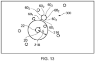
- FIG. 13 illustrates an example useful for understanding the invention.
- FIG. 13 is similar to FIG. 10 except that the selection of sound sources 10 for the first sub set 12 and the second sub-set 14 is different.
- the selection of loudspeaker transducers 60 for the first sub-set 42 of output audio channels 40 can also be different.
- the allocation of sound sources 10 to the sub-set 12, 14 is dependent upon a distance d from the position 22 of the user 20 in the sound space 2 to the plurality of sound sources 10. Those sound sources that are within a threshold distance 318 are allocated to the first sub-set 12 and some or all of the remaining sound sources 10 as allocated to the second sub-set 14.
- the rule for allocating a sound source 10 may have additional constraints such as, for example a position relative to the loudspeaker system 300 or the user 20.
- the first sub-set 42 of the multiple audio output channels 40 is for direct rendering and the second sub-set 44 of the multiple audio output channels 40 is for indirect rendering.
- the sound sources 10 that are close to the user are mapped to the 'direct' loudspeaker transducers 60 closest the user (the first set 42 of the output audio channels 40) the others to the 'indirect' loudspeaker transducers 60 (the second set 44 of the output audio channels 40). This will cause the sound sources 10 that are close to the user to be heard more clearly with less reverberation than the other sound sources 10 due to them being rendered from loudspeaker transducers 60 facing the user (the 'direct' set of loudspeaker transducers 60).
- the available audio paths for the multiple audio output channels 40 are either direct audio paths from loudspeaker transducers 60 or indirect audio paths from loudspeaker transducers 60.
- An allocation of the multiple audio output channels 40 to either the first sub-set 42 of the multiple audio output channels 40 or the second sub-set 44 of the multiple audio output channels 40 is dependent upon available direct audio paths and indirect audio paths from loudspeaker transducers 60.
- the apparatus 100 comprises means for:
- the loudspeaker system 300 comprise multiple loudspeaker transducers 60 that can be independently controlled, in other examples the loudspeaker system 300 may comprise only one loudspeaker transducer 60 for monophonic output.
- a loudspeaker transducer is a device that receives an electrical or electromagnetic signal and produces audible sound.
- a transducer 60 may comprise one or more elements, for example diaphragms, that are driven synchronously.
- the allocation of sound sources 10 to output audio channels 40 can thus include a hysteresis effect where rapid changes in allocation back and forth are prevented. As a consequence, a user may inadvertently or on purpose move slightly back and forth without repeatedly changing the allocation of sound sources to audio output channels 40.
- FIG. 7A illustrates the server 402 and the loudspeaker system 300 and the positioning system 404 as separate entities, in other examples any combination of the server 402 and the loudspeaker system 300 and the positioning system 404 may be integrated together as a single entity.
- the loudspeaker system 300 may comprise the server 402 and/or comprise some or all of the positioning system 404.
- the allocation can be fully automatic or partially automatic (automatic). Parameters used in the allocation may be varied by the user giving the user control over the allocation. For example, the user may adjust the division between 'indirect' or 'direct' sound sources and/or adjust the division between 'indirect' or 'direct' audio output channels 40 e.g. loudspeaker transducers 60.
- the user may change the listening point, defined by the loudspeaker position, manually, for example, using a user interface on the apparatus 100.
- a user 50 has access to spatial audio content (e.g. 6DoF/volumetric audio content) 423 that he wants to listen to. It may, for example, relate to an audio space 2 comprising musical instrument tracks as sound sources 10 that have been placed in different positions in the sound space 2. The user 50 wants to listen to the volumetric content 423, but does not have access to an appropriate speaker setup and does not want to listen to it using headphones.
- spatial audio content e.g. 6DoF/volumetric audio content
- sound sources 10 depicted in the FIG. 9 depict the positions of the sound sources (audio objects) in the virtual, 6DoF sound space 2. They do not depict the positions of the sound objects 10 as perceived by the user; the user perceives the rendered audio from the direction of the loudspeaker system 300 (direct sound sources) and hear parts of the spatial audio scene (indirect sound sources) via reflections from walls, furniture, etc. around the loudspeaker system 300.
- the output audio signal 30 may for example be a single channel signal (a monophonic signal) or a multi-channel signal formed by mixing audio signals representing spatial audio content.
- the user is able to re-position themselves in the real space, and that position is converted to a position within the sound space by the synthesis circuitry 434, and the sound scene rendered by the loudspeaker is determined by that position within the sound space.
- that new real position is converted to a new position within the sound space, and a new sound scene is rendered by the loudspeaker that is determined by that new position within the sound space.
- the sound scene rendered by the loudspeaker system 300 is a sound scene determined in dependence upon a corresponding position within the sound space of the user 10 and therefore has spatial characteristic it is not necessarily rendered as spatial audio because the loudspeaker cannot necessarily produce a spatially varying sound field that can locate sound sources at different positions.
- the synthesis circuitry 434 is configured to control an intensity of a sound source rendered in dependence upon a relative distance of the user from the loudspeaker.
- the intensity may scale as the inverse square of that distance.
- amplitude panning techniques may be used to create a sound object.
- To render spatial audio content fully left it is mixed completely to the left transducer of the loudspeaker, and correspondingly fully right when the spatial audio content is fully right.
- spatial audio content is mixed with equal gain to the two transducers of the loudspeaker.
- methods of amplitude panning are used to position the audio. For example, the known method of vector-base amplitude panning (VBAP) can be used
- the audio object is fed to a delay line and the direct sound and directional early reflections are read at suitable delays.
- the delays corresponding to early reflections can be obtained by analyzing the time delays of the early reflections from a measured or idealized room impulse response.
- the direct sound is fed to a source directivity and/or distance/gain attenuation modelling filter T0(z). This applies level adjustment and directionality processing.
- the attenuated and directionally-filtered direct sound is then passed to a reverberator which produces incoherent output.
- Each of the directional early reflections is fed to a source directivity and/or distance/gain attenuation modelling filter Ti(z). This applies level adjustment and directionality processing.
- the attenuated and directionally-filtered direct sound and the attenuated and directionally-filtered directional early reflections are mixed together with the incoherent output at a mixer.
- Control parameters may be used to control delays in the delay line; directivity and/or distance/gain at the filters; reverberation parameters of the reverberator; the respective gains applied to the directionally-filtered direct sound and the attenuated and directionally-filtered directional early reflections and the incoherent output, at the mixer.
- control parameters may be included in or associated with the audio content 423.
- the control parameters vary based on loudspeaker position and user position to achieve the effects described above.
- Distance rendering is in practice done by modifying the gain and direct to indirect ratio (or direct to ambient ratio).
- the direct signal gain can be modified according to 1/distance so that sounds which are farther away get quieter inversely proportionally to the distance.
- the direct to indirect ratio decreases when objects get farther.
- a simple implementation can keep the indirect gain constant within the listening space and then apply distance/gain attenuation to the direct part.
- gain for direct is maximal when the sound object is close and gain for indirect is maximal when the sound object is far.
- the other audio objects are processed similarly, and then summed together to form a monophonic output as the audio signal 30.
- the audio signal content in this single channel reflects the object position in the audio scene if room reflections are modified and synthesized according to object position in the audio scene. However, it does not contain spatial information which would enable creating a spatial percept for the listener.
- the audio content 423 may encode the spatial audio as audio objects, in other examples the spatial audio may be encoded as audio signals with parametric side information.
- the audio signals can be, for example, First Order Ambisonics (FOA) or its special case B-format, Higher Order Ambisonics (HOA) signals or mid-side stereo.
- FOA First Order Ambisonics
- HOA Higher Order Ambisonics
- synthesis which utilizes the audio signals and the parametric metadata is used to synthesize the audio scene so that a desired spatial perception is created.
- the parametric metadata may be produced by different techniques.
- Nokia's spatial audio capture OZO Audio
- Directional Audio Coding DirAC
- the parametric metadata may for example comprise:
- the energy-split parameters may be a ratio of diffuse energy to total energy, for example, as applied in the context of DirAC.
- the indirect version of the virtual sound source is passed through a decorrelator.
- the direct version of the virtual sound source is not.
- the synthesis circuitry 434 controls the audio signal 30 by modifying the parametric metadata for each time-space frequency tile and treating each time-space frequency tile as a separate virtual sound source.
- the additional gains are controlled via control parameters.
- the resulting direct version of the virtual sound source and indirect version of the virtual sound source are mixed together at a mixer to produce an audio signal for that virtual sound source.
- the audio signals for the multiple virtual sound sources are mixed together to create the output audio signal.
- VBAP and creation of loudspeaker signals can be omitted and the mono mix created directly from summed output of direct and indirect versions for each time-frequency tile.
- MPEG-I Audio is currently developing spatial audio formats. This disclosure enables such an audio format to be rendered on lower capability devices, for example, stereo (without binaural rendering) and/or monophonic playback capable devices.
- the apparatus 100 may comprise the loudspeaker system 300 and positioning system 404 within a portable electronic device.
- the position of the user 50 is tracked by tracking a head position of a user 50 of the portable electronic device using a camera of the portable electronic device.
- the above described examples find application as enabling components of: automotive systems; telecommunication systems; electronic systems including consumer electronic products; distributed computing systems; media systems for generating or rendering media content including audio, visual and audio visual content and mixed, mediated, virtual and/or augmented reality; personal systems including personal health systems or personal fitness systems; navigation systems; user interfaces also known as human machine interfaces; networks including cellular, non-cellular, and optical networks; ad-hoc networks; the internet; the internet of things; virtualized networks; and related software and services.
- a property of the instance can be a property of only that instance or a property of the class or a property of a sub-class of the class that includes some but not all of the instances in the class. It is therefore implicitly disclosed that a feature described with reference to one example but not with reference to another example, can where possible be used in that other example as part of a working combination but does not necessarily have to be used in that other example.
- 'a' or 'the' is used in this document with an inclusive not an exclusive meaning. That is any reference to X comprising a/the Y indicates that X may comprise only one Y or may comprise more than one Y unless the context clearly indicates the contrary. If it is intended to use 'a' or 'the' with an exclusive meaning then it will be made clear in the context. In some circumstances the use of 'at least one' or 'one or more' may be used to emphasis an inclusive meaning but the absence of these terms should not be taken to infer and exclusive meaning.
- 'example' or 'for example' or 'can' or 'may' in the text denotes, whether explicitly stated or not, that such features or functions are present in at least the described example, whether described as an example or not, and that they can be, but are not necessarily, present in some of or all other examples.
- 'example', 'for example', 'can' or 'may' refers to a particular instance in a class of examples.
- a property of the instance can be a property of only that instance or a property of the class or a property of a sub-class of the class that includes some but not all of the instances in the class. It is therefore implicitly disclosed that a feature described with reference to one example but not with reference to another example, can where possible be used in that other example as part of a working combination but does not necessarily have to be used in that other example
Landscapes
- Engineering & Computer Science (AREA)
- Physics & Mathematics (AREA)
- Acoustics & Sound (AREA)
- Signal Processing (AREA)
- Multimedia (AREA)
- Stereophonic System (AREA)
Claims (7)
- Appareil comprenant des moyens pour :obtenir une indication d'une orientation d'un système de haut-parleur comprenant de multiples transducteurs de haut-parleur mis en grappe autour d'une première position de référence, la première position de référence étant une position de référence dans l'espace réel ;obtenir une position (52) variable d'un utilisateur (50) dans l'espace réel (54) ;mapper la position (52) de l'utilisateur (50) dans l'espace réel (54) à une position (22) de l'utilisateur (20) dans un espace sonore (2), dans lequel l'espace sonore comprend une pluralité de sources sonores ;allouer la pluralité de sources sonores à un premier sous-ensemble de la pluralité de sources sonores ou à un deuxième sous-ensemble de la pluralité de sources sonores ;allouer de multiples canaux de sortie audio à un premier sous-ensemble des multiples canaux de sortie audio ou à un deuxième sous-ensemble des multiples canaux de sortie audio ; etcommander un signal audio de sortie (30) pour rendre une scène sonore par le système de haut-parleur, la scène sonore étant déterminée en fonction de l'orientation du système de haut-parleur dans l'espace réel et de la position variable de l'utilisateur dans l'espace réel, dans lequel de multiples canaux de sortie audio (40) sont chacun associés à un transducteur de haut-parleur différent des transducteurs de haut-parleur, de sorte qu'un premier ensemble des multiples transducteurs de haut-parleur corresponde à un premier sous-ensemble des multiples canaux de sortie audio, et qu'un deuxième ensemble des multiples transducteurs de haut-parleur corresponde à un deuxième sous-ensemble des multiples canaux de sortie audio, les multiples canaux de sortie audio étant des canaux de sortie audio physiques, de sorte que le rendu du premier sous-ensemble (12) de la pluralité de sources sonores (10) se fasse via au moins le premier sous-ensemble (42) des multiples canaux de sortie audio (40), et que le rendu du deuxième sous-ensemble (14) de la pluralité de sources sonores (10) se fasse via au moins le deuxième sous-ensemble (44) des multiples canaux de sortie audio (40),dans lequel une allocation d'une pluralité de sources sonores (10) au premier sous-ensemble (12) de la pluralité de sources sonores (10) ou au deuxième sous-ensemble (14) de la pluralité de sources sonores (10) dépend d'au moins une position (22) de l'utilisateur (20) dans l'espace sonore (2) par rapport à une deuxième position de référence, la deuxième position de référence étant une position de référence dans l'espace sonore, et dans lequel l'allocation au premier sous-ensemble de sources sonores est une allocation qui provoque un rendu direct, et l'allocation au deuxième sous-ensemble de sources sonores est une allocation qui provoque un rendu indirect ;dans lequel une allocation des multiples canaux de sortie audio (40) au premier sous-ensemble (42) des multiples canaux de sortie audio (40) ou au deuxième sous-ensemble (44) des multiples canaux de sortie audio (40) dépend de chemins audio disponibles pour les multiples canaux de sortie audio (40), dans lequel un chemin audio pour un canal de sortie audio est un chemin audio disponible s'il est un chemin audio direct vers l'utilisateur dans l'espace réel à partir d'un transducteur de haut-parleur des multiples transducteurs de haut-parleur, et dans lequel un canal de sortie audio est alloué au premier sous-ensemble des multiples canaux de sortie audio si le canal de sortie audio dispose d'un chemin audio disponible, et est alloué au deuxième sous-ensemble des multiples canaux de sortie audio si le canal de sortie audio ne dispose pas d'un chemin audio disponible,et dans lequel le premier ensemble des multiples transducteurs de haut-parleur comprend N transducteurs de haut-parleur des multiples transducteurs de haut-parleur qui sont les plus proches de l'utilisateur, et le deuxième ensemble des multiples transducteurs de haut-parleur comprend certains ou la totalité des autres transducteurs de haut-parleur des multiples transducteurs de haut-parleur.
- Appareil selon l'une des revendications précédentes, dans lequel les sources sonores pour le rendu direct et les sources sonores pour le rendu indirect sont identifiées sur la base de la position de l'utilisateur dans l'espace sonore.
- Appareil selon l'une des revendications précédentes, dans lequel une allocation d'une pluralité de sources sonores au premier sous-ensemble ou au deuxième sous-ensemble dépend d'au moins une position de l'utilisateur dans l'espace sonore par rapport à la pluralité de sources sonores.
- Système comprenant l'appareil selon l'une des revendications précédentes et le système de haut-parleur,dans lequel la première position de référence est au plus à une première distance des multiples transducteurs, et dans lequel la première position de référence est à une deuxième distance de la position de l'utilisateur dans l'espace réel, etdans lequel la première distance est inférieure à la deuxième distance.
- Système selon la revendication 4, dans lequel les multiples transducteurs mis en grappe autour de la première position de référence sont orientés vers l'extérieur, à l'opposé de la première position de référence.
- Procédé comprenant les étapes suivantes :obtenir une indication d'une orientation d'un système de haut-parleur comprenant de multiples transducteurs de haut-parleur mis en grappe autour d'une première position de référence, la première position de référence étant une position de référence dans l'espace réel ;obtenir une position (52) variable d'un utilisateur (50) dans l'espace réel (54) ;mapper la position (52) de l'utilisateur (50) dans l'espace réel (54) à une position (22) de l'utilisateur (20) dans un espace sonore (2), dans lequel l'espace sonore comprend une pluralité de sources sonores ;allouer la pluralité de sources sonores à un premier sous-ensemble de la pluralité de sources sonores ou à un deuxième sous-ensemble de la pluralité de sources sonores ;allouer de multiples canaux de sortie audio à un premier sous-ensemble des multiples canaux de sortie audio ou à un deuxième sous-ensemble des multiples canaux de sortie audio ; etcommander un signal audio de sortie (30) pour rendre une scène sonore par le système de haut-parleur, la scène sonore étant déterminée en fonction de l'orientation du système de haut-parleur dans l'espace réel et de la position variable de l'utilisateur dans l'espace réel, dans lequel de multiples canaux de sortie audio (40) sont chacun associés à un transducteur de haut-parleur différent des multiples transducteurs de haut-parleur, de sorte qu'un premier ensemble des multiples transducteurs de haut-parleur corresponde à un premier sous-ensemble des multiples canaux de sortie audio, et qu'un deuxième ensemble des multiples transducteurs de haut-parleur corresponde à un deuxième sous-ensemble des multiples canaux de sortie audio, les multiples canaux de sortie audio étant des canaux de sortie physiques, de sorte que le rendu du premier sous-ensemble (12) de la pluralité de sources sonores (10) se fasse via au moins le premier sous-ensemble (42) des multiples canaux de sortie audio (40), et que le rendu du deuxième sous-ensemble (14) de la pluralité de sources sonores (10) se fasse via au moins le deuxième sous-ensemble (44) des multiples canaux de sortie audio (40),dans lequel une allocation d'une pluralité de sources sonores (10) au premier sous-ensemble (12) de la pluralité de sources sonores (10) ou au deuxième sous-ensemble (14) de la pluralité de sources sonores (10) dépend d'au moins une position (22) de l'utilisateur (20) dans l'espace sonore (2) par rapport à une deuxième position de référence, la deuxième position de référence étant une position de référence dans l'espace sonore, et dans lequel l'allocation au premier sous-ensemble de sources sonores est une allocation qui provoque un rendu direct, et l'allocation au deuxième sous-ensemble de sources sonores est une allocation qui provoque un rendu indirect ;dans lequel une allocation des multiples canaux de sortie audio (40) au premier sous-ensemble (42) des multiples canaux de sortie audio (40) ou au deuxième sous-ensemble (44) des multiples canaux de sortie audio (40) dépend de chemins audio disponibles pour les multiples canaux de sortie audio (40), dans lequel un chemin audio pour un canal de sortie audio est un chemin audio disponible s'il est un chemin audio direct vers l'utilisateur dans l'espace réel à partir d'un transducteur de haut-parleur des multiples transducteurs de haut-parleur, et dans lequel un canal de sortie audio est alloué au premier sous-ensemble des multiples canaux de sortie audio si le canal de sortie audio dispose d'un chemin audio disponible, et est alloué au deuxième sous-ensemble des multiples canaux de sortie audio si le canal de sortie audio ne dispose pas d'un chemin audio disponible,et dans lequel le premier ensemble des multiples transducteurs de haut-parleur comprend N transducteurs de haut-parleur des multiples transducteurs de haut-parleur qui sont les plus proches de l'utilisateur, et le deuxième ensemble des multiples transducteurs de haut-parleur comprend certains ou la totalité des autres transducteurs de haut-parleur des multiples transducteurs de haut-parleur.
- Programme informatique qui, lorsqu'il est exécuté sur un ou plusieurs processeurs, provoque les opérations suivantes :obtenir une indication d'une orientation d'un système de haut-parleur comprenant de multiples transducteurs de haut-parleur mis en grappe autour d'une première position de référence, la première position de référence étant une position de référence dans l'espace réel ;obtenir une position variable d'un utilisateur dans l'espace réel ;mapper la position (50) de l'utilisateur (50) dans l'espace réel à une position (22) de l'utilisateur (20) dans un espace sonore (2), dans lequel l'espace sonore comprend une pluralité de sources sonores ;allouer la pluralité de sources sonores à un premier sous-ensemble de la pluralité de sources sonores ou à un deuxième sous-ensemble de la pluralité de sources sonores ;allouer de multiples canaux de sortie audio à un premier sous-ensemble des multiples canaux de sortie audio ou à un deuxième sous-ensemble des multiples canaux de sortie audio ; etcommander un signal audio de sortie (30) pour rendre une scène sonore par le système de haut-parleur, la scène sonore étant déterminée en fonction de l'orientation du système de haut-parleur dans l'espace réel et de la position variable de l'utilisateur dans l'espace réel, dans lequel de multiples canaux de sortie audio (40) sont chacun associés à un transducteur de haut-parleur différent des multiples transducteurs de haut-parleur, de sorte qu'un premier ensemble des multiples transducteurs de haut-parleur corresponde à un premier sous-ensemble des multiples canaux de sortie audio, et qu'un deuxième ensemble des multiples transducteurs de haut-parleur corresponde à un deuxième sous-ensemble des multiples canaux de sortie audio, les multiples canaux de sortie audio étant des canaux de sortie audio physiques, de sorte que le rendu du premier sous-ensemble (12) de la pluralité de sources sonores (10) se fasse via au moins le premier sous-ensemble (42) des multiples canaux de sortie audio (40), et que le rendu du deuxième sous-ensemble (14) de la pluralité de sources sonores (10) se fasse via au moins le deuxième sous-ensemble (44) des multiples canaux de sortie audio (40),dans lequel une allocation d'une pluralité de sources sonores (10) au premier sous-ensemble (12) de la pluralité de sources sonores (10) ou au deuxième sous-ensemble (14) de la pluralité de sources sonores (10) dépend d'au moins une position (22) de l'utilisateur (20) dans l'espace sonore (2) par rapport à une deuxième position de référence, la deuxième position de référence étant une position de référence dans l'espace sonore, et dans lequel l'allocation au premier sous-ensemble de sources sonores est une allocation qui provoque un rendu direct, et l'allocation au deuxième sous-ensemble de sources sonores est une allocation qui provoque un rendu indirect ;dans lequel une allocation des multiples canaux de sortie audio (40) au premier sous-ensemble (42) des multiples canaux de sortie audio (40) ou au deuxième sous-ensemble (44) des multiples canaux de sortie audio (40) dépend de chemins audio disponibles pour les multiples canaux de sortie audio (40),dans lequel un chemin audio pour un canal de sortie audio est un chemin audio disponible s'il est un chemin direct vers l'utilisateur dans l'espace réel à partir d'un transducteur de haut-parleur des multiples transducteurs de haut-parleur, et dans lequel un canal de sortie audio est alloué au premier sous-ensemble des multiples canaux de sortie audio si le canal de sortie audio dispose d'un chemin audio disponible, et est alloué au deuxième sous-ensemble des multiples canaux de sortie audio si le canal de sortie audio ne dispose pas d'un chemin audio disponible,et dans lequel le premier ensemble des multiples transducteurs de haut-parleur comprend N transducteurs de haut-parleur des multiples transducteurs de haut-parleur qui sont les plus proches de l'utilisateur, et le deuxième ensemble des multiples transducteurs de haut-parleur comprend certains ou la totalité des autres transducteurs de haut-parleur des multiples transducteurs de haut-parleur.
Priority Applications (3)
| Application Number | Priority Date | Filing Date | Title |
|---|---|---|---|
| EP18176444.0A EP3579584B1 (fr) | 2018-06-07 | 2018-06-07 | Commande de rendu d'une scène audio spatiale |
| US17/053,297 US11337020B2 (en) | 2018-06-07 | 2019-05-29 | Controlling rendering of a spatial audio scene |
| PCT/EP2019/063969 WO2019233855A1 (fr) | 2018-06-07 | 2019-05-29 | Commande de rendu d'une scène audio spatiale |
Applications Claiming Priority (1)
| Application Number | Priority Date | Filing Date | Title |
|---|---|---|---|
| EP18176444.0A EP3579584B1 (fr) | 2018-06-07 | 2018-06-07 | Commande de rendu d'une scène audio spatiale |
Publications (2)
| Publication Number | Publication Date |
|---|---|
| EP3579584A1 EP3579584A1 (fr) | 2019-12-11 |
| EP3579584B1 true EP3579584B1 (fr) | 2025-07-02 |
Family
ID=62563056
Family Applications (1)
| Application Number | Title | Priority Date | Filing Date |
|---|---|---|---|
| EP18176444.0A Active EP3579584B1 (fr) | 2018-06-07 | 2018-06-07 | Commande de rendu d'une scène audio spatiale |
Country Status (3)
| Country | Link |
|---|---|
| US (1) | US11337020B2 (fr) |
| EP (1) | EP3579584B1 (fr) |
| WO (1) | WO2019233855A1 (fr) |
Families Citing this family (8)
| Publication number | Priority date | Publication date | Assignee | Title |
|---|---|---|---|---|
| EP3579584B1 (fr) * | 2018-06-07 | 2025-07-02 | Nokia Technologies Oy | Commande de rendu d'une scène audio spatiale |
| US11393101B2 (en) * | 2020-02-24 | 2022-07-19 | Harman International Industries, Incorporated | Position node tracking |
| GB2599359A (en) * | 2020-09-23 | 2022-04-06 | Nokia Technologies Oy | Spatial audio rendering |
| US11601776B2 (en) | 2020-12-18 | 2023-03-07 | Qualcomm Incorporated | Smart hybrid rendering for augmented reality/virtual reality audio |
| US20220312144A1 (en) * | 2021-03-24 | 2022-09-29 | Sony Group Corporation | Sound signal generation circuitry and sound signal generation method |
| US11659330B2 (en) * | 2021-04-13 | 2023-05-23 | Spatialx Inc. | Adaptive structured rendering of audio channels |
| EP4268477B1 (fr) | 2021-05-24 | 2026-03-04 | Samsung Electronics Co., Ltd. | Système de rendu audio intelligent utilisant des noeuds de haut-parleurs hétérogènes et procédé associé |
| EP4462423A1 (fr) * | 2023-05-08 | 2024-11-13 | Nokia Technologies Oy | Rendu de réverbération avec commande de démarrage |
Family Cites Families (12)
| Publication number | Priority date | Publication date | Assignee | Title |
|---|---|---|---|---|
| US5870484A (en) | 1995-09-05 | 1999-02-09 | Greenberger; Hal | Loudspeaker array with signal dependent radiation pattern |
| US20080273722A1 (en) | 2007-05-04 | 2008-11-06 | Aylward J Richard | Directionally radiating sound in a vehicle |
| US20110157322A1 (en) | 2009-12-31 | 2011-06-30 | Broadcom Corporation | Controlling a pixel array to support an adaptable light manipulator |
| WO2016048381A1 (fr) * | 2014-09-26 | 2016-03-31 | Nunntawi Dynamics Llc | Système audio avec zones configurables |
| IL243513B2 (en) * | 2016-01-07 | 2023-11-01 | Noveto Systems Ltd | System and method for audio communication |
| EP3319341A1 (fr) * | 2016-11-03 | 2018-05-09 | Nokia Technologies OY | Traitement audio |
| US20190036720A1 (en) * | 2017-07-31 | 2019-01-31 | Lenovo (Singapore) Pte. Ltd. | Method and device to select an electronic device based on delivery attributes |
| US10225656B1 (en) * | 2018-01-17 | 2019-03-05 | Harman International Industries, Incorporated | Mobile speaker system for virtual reality environments |
| EP3550860B1 (fr) * | 2018-04-05 | 2021-08-18 | Nokia Technologies Oy | Rendu de contenu audio spatial |
| EP3579584B1 (fr) * | 2018-06-07 | 2025-07-02 | Nokia Technologies Oy | Commande de rendu d'une scène audio spatiale |
| US20200008003A1 (en) * | 2018-07-02 | 2020-01-02 | Walmart Apollo, Llc | Presence-based volume control system |
| EP3617871A1 (fr) * | 2018-08-28 | 2020-03-04 | Koninklijke Philips N.V. | Appareil audio et procédé de traitement audio |
-
2018
- 2018-06-07 EP EP18176444.0A patent/EP3579584B1/fr active Active
-
2019
- 2019-05-29 US US17/053,297 patent/US11337020B2/en active Active
- 2019-05-29 WO PCT/EP2019/063969 patent/WO2019233855A1/fr not_active Ceased
Also Published As
| Publication number | Publication date |
|---|---|
| WO2019233855A1 (fr) | 2019-12-12 |
| US11337020B2 (en) | 2022-05-17 |
| EP3579584A1 (fr) | 2019-12-11 |
| US20210076152A1 (en) | 2021-03-11 |
Similar Documents
| Publication | Publication Date | Title |
|---|---|---|
| US11337020B2 (en) | Controlling rendering of a spatial audio scene | |
| US11140507B2 (en) | Rendering of spatial audio content | |
| Zotter et al. | Ambisonics: A practical 3D audio theory for recording, studio production, sound reinforcement, and virtual reality | |
| JP6878458B2 (ja) | 焦点距離に近い音源を強調する空間オーディオ処理 | |
| US8587631B2 (en) | Facilitating communications using a portable communication device and directed sound output | |
| CN108781341B (zh) | 音响处理方法及音响处理装置 | |
| CN113170271B (zh) | 用于处理立体声信号的方法和装置 | |
| Bates | The composition and performance of spatial music | |
| US10757528B1 (en) | Methods and systems for simulating spatially-varying acoustics of an extended reality world | |
| US10764709B2 (en) | Methods, apparatus and systems for dynamic equalization for cross-talk cancellation | |
| WO2016172111A1 (fr) | Traitement de données audio pour compenser une perte auditive partielle ou un environnement auditif indésirable | |
| TW201246060A (en) | Audio spatialization and environment simulation | |
| CN112806030A (zh) | 空间音频处理 | |
| EP3506080B1 (fr) | Traitement de scène audio | |
| WO2018197747A1 (fr) | Traitement spatial de signal audio | |
| JP2022536169A (ja) | 音場関連レンダリング | |
| EP4088488A1 (fr) | Appareil, procédés et programmes informatiques pour permettre la reproduction de signaux audio spatiaux | |
| CN116193196A (zh) | 虚拟环绕声渲染方法、装置、设备及存储介质 | |
| EP3613221A1 (fr) | Amélioration de lecture de haut-parleur à l'aide d'un signal audio traité en étendue spatiale | |
| TW202234385A (zh) | 用以呈現音訊物件之設備與方法 | |
| KR102921613B1 (ko) | 다채널 오디오 스테이션 청취 공간을 제공하는 음원의 공간적 위치 출력 조절 시스템 | |
| EP4226651B1 (fr) | Procédé d'émission de son et haut-parleur | |
| US20250350898A1 (en) | Object-based Audio Spatializer With Crosstalk Equalization |
Legal Events
| Date | Code | Title | Description |
|---|---|---|---|
| PUAI | Public reference made under article 153(3) epc to a published international application that has entered the european phase |
Free format text: ORIGINAL CODE: 0009012 |
|
| STAA | Information on the status of an ep patent application or granted ep patent |
Free format text: STATUS: THE APPLICATION HAS BEEN PUBLISHED |
|
| AK | Designated contracting states |
Kind code of ref document: A1 Designated state(s): AL AT BE BG CH CY CZ DE DK EE ES FI FR GB GR HR HU IE IS IT LI LT LU LV MC MK MT NL NO PL PT RO RS SE SI SK SM TR |
|
| AX | Request for extension of the european patent |
Extension state: BA ME |
|
| STAA | Information on the status of an ep patent application or granted ep patent |
Free format text: STATUS: REQUEST FOR EXAMINATION WAS MADE |
|
| 17P | Request for examination filed |
Effective date: 20200611 |
|
| RBV | Designated contracting states (corrected) |
Designated state(s): AL AT BE BG CH CY CZ DE DK EE ES FI FR GB GR HR HU IE IS IT LI LT LU LV MC MK MT NL NO PL PT RO RS SE SI SK SM TR |
|
| STAA | Information on the status of an ep patent application or granted ep patent |
Free format text: STATUS: EXAMINATION IS IN PROGRESS |
|
| 17Q | First examination report despatched |
Effective date: 20201027 |
|
| GRAP | Despatch of communication of intention to grant a patent |
Free format text: ORIGINAL CODE: EPIDOSNIGR1 |
|
| STAA | Information on the status of an ep patent application or granted ep patent |
Free format text: STATUS: GRANT OF PATENT IS INTENDED |
|
| INTG | Intention to grant announced |
Effective date: 20250127 |
|
| GRAS | Grant fee paid |
Free format text: ORIGINAL CODE: EPIDOSNIGR3 |
|
| GRAA | (expected) grant |
Free format text: ORIGINAL CODE: 0009210 |
|
| STAA | Information on the status of an ep patent application or granted ep patent |
Free format text: STATUS: THE PATENT HAS BEEN GRANTED |
|
| AK | Designated contracting states |
Kind code of ref document: B1 Designated state(s): AL AT BE BG CH CY CZ DE DK EE ES FI FR GB GR HR HU IE IS IT LI LT LU LV MC MK MT NL NO PL PT RO RS SE SI SK SM TR |
|
| REG | Reference to a national code |
Ref country code: GB Ref legal event code: FG4D |
|
| REG | Reference to a national code |
Ref country code: CH Ref legal event code: EP |
|
| REG | Reference to a national code |
Ref country code: IE Ref legal event code: FG4D |
|
| REG | Reference to a national code |
Ref country code: DE Ref legal event code: R096 Ref document number: 602018083123 Country of ref document: DE |
|
| REG | Reference to a national code |
Ref country code: NL Ref legal event code: MP Effective date: 20250702 |
|
| PG25 | Lapsed in a contracting state [announced via postgrant information from national office to epo] |
Ref country code: PT Free format text: LAPSE BECAUSE OF FAILURE TO SUBMIT A TRANSLATION OF THE DESCRIPTION OR TO PAY THE FEE WITHIN THE PRESCRIBED TIME-LIMIT Effective date: 20251103 |
|
| PG25 | Lapsed in a contracting state [announced via postgrant information from national office to epo] |
Ref country code: NL Free format text: LAPSE BECAUSE OF FAILURE TO SUBMIT A TRANSLATION OF THE DESCRIPTION OR TO PAY THE FEE WITHIN THE PRESCRIBED TIME-LIMIT Effective date: 20250702 |
|
| REG | Reference to a national code |
Ref country code: AT Ref legal event code: MK05 Ref document number: 1810679 Country of ref document: AT Kind code of ref document: T Effective date: 20250702 |
|
| PG25 | Lapsed in a contracting state [announced via postgrant information from national office to epo] |
Ref country code: IS Free format text: LAPSE BECAUSE OF FAILURE TO SUBMIT A TRANSLATION OF THE DESCRIPTION OR TO PAY THE FEE WITHIN THE PRESCRIBED TIME-LIMIT Effective date: 20251102 |
|
| PG25 | Lapsed in a contracting state [announced via postgrant information from national office to epo] |
Ref country code: NO Free format text: LAPSE BECAUSE OF FAILURE TO SUBMIT A TRANSLATION OF THE DESCRIPTION OR TO PAY THE FEE WITHIN THE PRESCRIBED TIME-LIMIT Effective date: 20251002 |
|
| REG | Reference to a national code |
Ref country code: LT Ref legal event code: MG9D |
|
| PG25 | Lapsed in a contracting state [announced via postgrant information from national office to epo] |
Ref country code: AT Free format text: LAPSE BECAUSE OF FAILURE TO SUBMIT A TRANSLATION OF THE DESCRIPTION OR TO PAY THE FEE WITHIN THE PRESCRIBED TIME-LIMIT Effective date: 20250702 |
|
| PG25 | Lapsed in a contracting state [announced via postgrant information from national office to epo] |
Ref country code: FI Free format text: LAPSE BECAUSE OF FAILURE TO SUBMIT A TRANSLATION OF THE DESCRIPTION OR TO PAY THE FEE WITHIN THE PRESCRIBED TIME-LIMIT Effective date: 20250702 |
|
| PG25 | Lapsed in a contracting state [announced via postgrant information from national office to epo] |
Ref country code: HR Free format text: LAPSE BECAUSE OF FAILURE TO SUBMIT A TRANSLATION OF THE DESCRIPTION OR TO PAY THE FEE WITHIN THE PRESCRIBED TIME-LIMIT Effective date: 20250702 |
|
| PG25 | Lapsed in a contracting state [announced via postgrant information from national office to epo] |
Ref country code: GR Free format text: LAPSE BECAUSE OF FAILURE TO SUBMIT A TRANSLATION OF THE DESCRIPTION OR TO PAY THE FEE WITHIN THE PRESCRIBED TIME-LIMIT Effective date: 20251003 |
|
| PG25 | Lapsed in a contracting state [announced via postgrant information from national office to epo] |
Ref country code: SE Free format text: LAPSE BECAUSE OF FAILURE TO SUBMIT A TRANSLATION OF THE DESCRIPTION OR TO PAY THE FEE WITHIN THE PRESCRIBED TIME-LIMIT Effective date: 20250702 Ref country code: CZ Free format text: LAPSE BECAUSE OF FAILURE TO SUBMIT A TRANSLATION OF THE DESCRIPTION OR TO PAY THE FEE WITHIN THE PRESCRIBED TIME-LIMIT Effective date: 20250702 |
|
| PG25 | Lapsed in a contracting state [announced via postgrant information from national office to epo] |
Ref country code: LV Free format text: LAPSE BECAUSE OF FAILURE TO SUBMIT A TRANSLATION OF THE DESCRIPTION OR TO PAY THE FEE WITHIN THE PRESCRIBED TIME-LIMIT Effective date: 20250702 |
|
| PG25 | Lapsed in a contracting state [announced via postgrant information from national office to epo] |
Ref country code: PL Free format text: LAPSE BECAUSE OF FAILURE TO SUBMIT A TRANSLATION OF THE DESCRIPTION OR TO PAY THE FEE WITHIN THE PRESCRIBED TIME-LIMIT Effective date: 20250702 Ref country code: BG Free format text: LAPSE BECAUSE OF FAILURE TO SUBMIT A TRANSLATION OF THE DESCRIPTION OR TO PAY THE FEE WITHIN THE PRESCRIBED TIME-LIMIT Effective date: 20250702 |
|
| PG25 | Lapsed in a contracting state [announced via postgrant information from national office to epo] |
Ref country code: RS Free format text: LAPSE BECAUSE OF FAILURE TO SUBMIT A TRANSLATION OF THE DESCRIPTION OR TO PAY THE FEE WITHIN THE PRESCRIBED TIME-LIMIT Effective date: 20251002 |
|
| PG25 | Lapsed in a contracting state [announced via postgrant information from national office to epo] |
Ref country code: ES Free format text: LAPSE BECAUSE OF FAILURE TO SUBMIT A TRANSLATION OF THE DESCRIPTION OR TO PAY THE FEE WITHIN THE PRESCRIBED TIME-LIMIT Effective date: 20250702 |
|
| PG25 | Lapsed in a contracting state [announced via postgrant information from national office to epo] |
Ref country code: SM Free format text: LAPSE BECAUSE OF FAILURE TO SUBMIT A TRANSLATION OF THE DESCRIPTION OR TO PAY THE FEE WITHIN THE PRESCRIBED TIME-LIMIT Effective date: 20250702 |
|
| PG25 | Lapsed in a contracting state [announced via postgrant information from national office to epo] |
Ref country code: DK Free format text: LAPSE BECAUSE OF FAILURE TO SUBMIT A TRANSLATION OF THE DESCRIPTION OR TO PAY THE FEE WITHIN THE PRESCRIBED TIME-LIMIT Effective date: 20250702 |
|
| PG25 | Lapsed in a contracting state [announced via postgrant information from national office to epo] |
Ref country code: IT Free format text: LAPSE BECAUSE OF FAILURE TO SUBMIT A TRANSLATION OF THE DESCRIPTION OR TO PAY THE FEE WITHIN THE PRESCRIBED TIME-LIMIT Effective date: 20250702 |