EP3581443B1 - Dispositif de communication pour un véhicule pour effectuer une transmission de données sans contact - Google Patents
Dispositif de communication pour un véhicule pour effectuer une transmission de données sans contact Download PDFInfo
- Publication number
- EP3581443B1 EP3581443B1 EP19169777.0A EP19169777A EP3581443B1 EP 3581443 B1 EP3581443 B1 EP 3581443B1 EP 19169777 A EP19169777 A EP 19169777A EP 3581443 B1 EP3581443 B1 EP 3581443B1
- Authority
- EP
- European Patent Office
- Prior art keywords
- vehicle
- communication device
- power supply
- communication
- deep sleep
- Prior art date
- Legal status (The legal status is an assumption and is not a legal conclusion. Google has not performed a legal analysis and makes no representation as to the accuracy of the status listed.)
- Active
Links
Images
Classifications
-
- B—PERFORMING OPERATIONS; TRANSPORTING
- B60—VEHICLES IN GENERAL
- B60R—VEHICLES, VEHICLE FITTINGS, OR VEHICLE PARTS, NOT OTHERWISE PROVIDED FOR
- B60R25/00—Fittings or systems for preventing or indicating unauthorised use or theft of vehicles
- B60R25/40—Features of the power supply for the anti-theft system, e.g. anti-theft batteries, back-up power supply or means to save battery power
- B60R25/403—Power supply in the vehicle
-
- B—PERFORMING OPERATIONS; TRANSPORTING
- B60—VEHICLES IN GENERAL
- B60R—VEHICLES, VEHICLE FITTINGS, OR VEHICLE PARTS, NOT OTHERWISE PROVIDED FOR
- B60R25/00—Fittings or systems for preventing or indicating unauthorised use or theft of vehicles
- B60R25/40—Features of the power supply for the anti-theft system, e.g. anti-theft batteries, back-up power supply or means to save battery power
- B60R25/406—Power supply in the remote key
-
- G—PHYSICS
- G06—COMPUTING OR CALCULATING; COUNTING
- G06F—ELECTRIC DIGITAL DATA PROCESSING
- G06F1/00—Details not covered by groups G06F3/00 - G06F13/00 and G06F21/00
- G06F1/26—Power supply means, e.g. regulation thereof
- G06F1/32—Means for saving power
- G06F1/3203—Power management, i.e. event-based initiation of a power-saving mode
- G06F1/3206—Monitoring of events, devices or parameters that trigger a change in power modality
-
- G—PHYSICS
- G06—COMPUTING OR CALCULATING; COUNTING
- G06F—ELECTRIC DIGITAL DATA PROCESSING
- G06F1/00—Details not covered by groups G06F3/00 - G06F13/00 and G06F21/00
- G06F1/26—Power supply means, e.g. regulation thereof
- G06F1/32—Means for saving power
- G06F1/3203—Power management, i.e. event-based initiation of a power-saving mode
- G06F1/3234—Power saving characterised by the action undertaken
-
- G—PHYSICS
- G07—CHECKING-DEVICES
- G07C—TIME OR ATTENDANCE REGISTERS; REGISTERING OR INDICATING THE WORKING OF MACHINES; GENERATING RANDOM NUMBERS; VOTING OR LOTTERY APPARATUS; ARRANGEMENTS, SYSTEMS OR APPARATUS FOR CHECKING NOT PROVIDED FOR ELSEWHERE
- G07C9/00—Individual registration on entry or exit
- G07C9/00174—Electronically operated locks; Circuits therefor; Nonmechanical keys therefor, e.g. passive or active electrical keys or other data carriers without mechanical keys
- G07C9/00309—Electronically operated locks; Circuits therefor; Nonmechanical keys therefor, e.g. passive or active electrical keys or other data carriers without mechanical keys operated with bidirectional data transmission between data carrier and locks
-
- B—PERFORMING OPERATIONS; TRANSPORTING
- B60—VEHICLES IN GENERAL
- B60R—VEHICLES, VEHICLE FITTINGS, OR VEHICLE PARTS, NOT OTHERWISE PROVIDED FOR
- B60R2325/00—Indexing scheme relating to vehicle anti-theft devices
- B60R2325/10—Communication protocols, communication systems of vehicle anti-theft devices
- B60R2325/103—Near field communication [NFC]
-
- B—PERFORMING OPERATIONS; TRANSPORTING
- B60—VEHICLES IN GENERAL
- B60R—VEHICLES, VEHICLE FITTINGS, OR VEHICLE PARTS, NOT OTHERWISE PROVIDED FOR
- B60R2325/00—Indexing scheme relating to vehicle anti-theft devices
- B60R2325/20—Communication devices for vehicle anti-theft devices
- B60R2325/205—Mobile phones
-
- G—PHYSICS
- G07—CHECKING-DEVICES
- G07C—TIME OR ATTENDANCE REGISTERS; REGISTERING OR INDICATING THE WORKING OF MACHINES; GENERATING RANDOM NUMBERS; VOTING OR LOTTERY APPARATUS; ARRANGEMENTS, SYSTEMS OR APPARATUS FOR CHECKING NOT PROVIDED FOR ELSEWHERE
- G07C9/00—Individual registration on entry or exit
- G07C9/00174—Electronically operated locks; Circuits therefor; Nonmechanical keys therefor, e.g. passive or active electrical keys or other data carriers without mechanical keys
- G07C9/00309—Electronically operated locks; Circuits therefor; Nonmechanical keys therefor, e.g. passive or active electrical keys or other data carriers without mechanical keys operated with bidirectional data transmission between data carrier and locks
- G07C2009/00365—Electronically operated locks; Circuits therefor; Nonmechanical keys therefor, e.g. passive or active electrical keys or other data carriers without mechanical keys operated with bidirectional data transmission between data carrier and locks in combination with a wake-up circuit
- G07C2009/00373—Electronically operated locks; Circuits therefor; Nonmechanical keys therefor, e.g. passive or active electrical keys or other data carriers without mechanical keys operated with bidirectional data transmission between data carrier and locks in combination with a wake-up circuit whereby the wake-up circuit is situated in the lock
-
- G—PHYSICS
- G07—CHECKING-DEVICES
- G07C—TIME OR ATTENDANCE REGISTERS; REGISTERING OR INDICATING THE WORKING OF MACHINES; GENERATING RANDOM NUMBERS; VOTING OR LOTTERY APPARATUS; ARRANGEMENTS, SYSTEMS OR APPARATUS FOR CHECKING NOT PROVIDED FOR ELSEWHERE
- G07C9/00—Individual registration on entry or exit
- G07C9/00174—Electronically operated locks; Circuits therefor; Nonmechanical keys therefor, e.g. passive or active electrical keys or other data carriers without mechanical keys
- G07C2009/00634—Power supply for the lock
Definitions
- the present invention relates to a communication device for a vehicle for performing contactless data transmission. Furthermore, the invention relates to a system with such a communication device and to a method for the energy-saving operation of at least one component of a vehicle.
- the problem has emerged that the power consumption in such systems can be too high for a longer vehicle standstill. For example, after the vehicle has been transported for a long time, the vehicle battery may not have a sufficient charge level.
- a communication device for a vehicle for carrying out a contactless transmission of energy and/or data between (vehicle-internal) vehicle electronics and a vehicle-external device.
- the communication device is designed to activate a vehicle-internal (electrical) energy supply of the communication device by means of an external vehicle (electrical) energy supply at the communication device.
- the vehicle-external power supply are made to activate the vehicle's internal power supply. The activation refers z. B.
- the previous deactivation of the vehicle's internal energy supply ie the change from active mode to deep sleep mode, z. B. by a communication command via the contactless data transmission. It may then be possible that the communication device can no longer be operated in passive mode without establishing the vehicle-external energy supply. Only and/or exclusively the described activation of the vehicle-internal energy supply by means of the vehicle-external energy supply can result in the communication device also being able to be supplied with energy again in-vehicle. After the complete activation (ie the end of an automated activation process), the vehicle-external energy supply can therefore be deactivated again, and the communication device can still continue to be operated in active mode. The vehicle-external power supply is therefore no longer required, and instead the communication device itself can even provide a power supply for the vehicle-external (external in relation to the vehicle) device without contact (e.g. by means of induction).
- the vehicle-internal energy supply can thus be, for example, an energy supply from an energy source, such as an accumulator, of the vehicle.
- the vehicle-external energy supply is z. B. a power supply from an energy source, z. B. the vehicle-external device, which is located outside of the vehicle accordingly.
- Contactless data transmission is z. B. a near-field transmission (in particular NFC), so that the communication device can be designed as a near-field communication device (in particular NFC interface).
- the vehicle is z. B. as a motor vehicle and / or passenger vehicle and / or electric vehicle and / or hybrid vehicle.
- the vehicle has an on-board energy source as an energy store in order to supply electrical components of the vehicle with electrical energy via an on-board network.
- energy supply can refer to a supply of electrical energy, e.g. As current and / or voltage related.
- the vehicle can have at least one outside door handle have, in which, for example.
- the communication device according to the invention can be arranged.
- a communication element is provided for contactless coupling to the vehicle-external device in order to provide the communication device with the vehicle-external energy supply via the coupling to the communication device in a deep sleep mode, in particular passive deep sleep mode.
- the communication element is z. B. formed as a coil, preferably near-field transmission coil, to provide an inductive coupling.
- the communication element can be used both for data transmission (e.g. by means of NFC) and for energy transmission.
- the communication element is preferably attached to a circuit board and conductively connected to an evaluation device for carrying out the near-field transmission, e.g. B. a microcontroller or the like connected. This has the advantage that a cost-effective, space-saving and simple design of the communication device can be used to activate the vehicle's internal energy supply.
- the communication device can be able to be supplied with energy independently of the vehicle's internal energy supply in a deep sleep mode. It can therefore be possible for the energy supply and thus the operation of the communication device to be enabled by an external energy source in the vehicle without the need for an internal vehicle energy supply, ie the energy supply from the vehicle's energy source.
- the vehicle-side energy source is z. B. an accumulator of the vehicle.
- the in-vehicle energy supply does not mean that only an intermediate store (an energy storage element such as a capacitor or the like) is used by the communication device—but always an in-vehicle energy source such as an accumulator. Because even with the vehicle-external energy supply, it may be necessary to use such buffers in order to provide sufficient buffer storage of electrical energy for operation of the communication device.
- a communication element which is connected via a first interconnection to an energy storage element, in particular a capacitor, in order to provide the vehicle-external energy supply in a passive deep sleep mode, in particular for waking up the vehicle electronics, and preferably via a second interconnection is connected to a supply connection for connection to a vehicle-side energy source in order to provide the vehicle-internal energy supply in an active mode for carrying out an active data transmission with the communication device.
- the active mode can thus be used to carry out data transmission by the communication device, e.g. B. for authentication and preferably activation of safety-related vehicle functions based on the authentication.
- the deep sleep mode In order to get into this mode and possibly also provide other vehicle functions through the vehicle electronics, it may be necessary to wake up from the deep sleep mode.
- an energy supply is briefly (via the intermediate storage of the energy storage element) in the communication device provided, which uses the energy of a vehicle-external energy source.
- the deep sleep mode can thus be implemented in a particularly energy-saving and in particular current-saving manner.
- the communication device is designed as an NFC interface, the NFC interface preferably being convertible from a deep sleep mode for passive communication to an active mode for active communication by providing the vehicle-external energy supply.
- This can involve active and passive communication within the meaning of the NFC standard. This provides a simple option, supported by many communication devices, for making the transition to the active mode.
- a communication element which is designed as an antenna and/or coil in order to provide the energy transmission to the vehicle-external energy supply and in particular also the data transmission by means of inductive coupling.
- the communication element is preferably designed as a near-field transmission coil, which is therefore already capable of transmitting energy.
- the vehicle-external energy supply can thus be provided in a cost-saving and space-saving manner.
- the communication device is designed to be arranged in a door handle and/or in a sensor and/or on a B-pillar of the vehicle. A particularly space-saving arrangement can thus be achieved.
- a power supply of at least the communication device (and/or also other electrical components of the vehicle) can be produced inside the vehicle and in the deep sleep mode the power supply can be produced, in particular exclusively, outside the vehicle.
- the system according to the invention thus brings with it the same advantages as have been described in detail with reference to a communication device according to the invention.
- the system can have a communication device according to the invention.
- the switching device is part of the vehicle and/or the vehicle electronics and/or the communication device and preferably cannot be reached manually from outside the vehicle in order to enable reliable switching.
- the vehicle-external device is preferably designed as a cell phone and/or smartphone and/or mobile communication device and/or identifier for authentication on the vehicle.
- the vehicle-external device preferably has a communication interface (in particular a communication unit) for near-field communication with the communication device.
- the vehicle-external device can be designed as a mobile device, i. H. as a wearable device.
- At least one vehicle-side energy source is provided for the energy supply of the, in particular all, vehicle electronics of the vehicle, wherein preferably the energy supply by the vehicle-side energy source can be completely deactivated in deep sleep mode and can be completely restored in active mode, preferably by changing wake up the vehicle from deep sleep mode to active mode.
- the entire vehicle electronics can preferably have all of the vehicle's control units or the majority of the vehicle's control units, in order in particular to provide the deep sleep mode as a transport mode. This means that the deep sleep mode is particularly suitable for a longer standstill of the vehicle, e.g. B. in a transport by ship or the like.
- the communication device for communication with the external device is designed in the form of a mobile communication device, preferably a mobile radio device, preferably a smartphone, with preferably a communication element of the communication device for contactless, in particular inductive, energy consumption from a communication unit, in particular an active one NFC unit, the device is designed for off-board power supply.
- Both the communication element and the communication unit can have at least one coil in order to be loosely coupled to one another for reliable energy transmission.
- the communication device is designed to carry out an authentication of the external device based on the data transmission, in particular only in active mode or both in active mode and in deep sleep mode when the vehicle-external energy supply is established. For example, a code is transmitted to enable secure authentication.
- the communication device is designed in active mode to repeatedly, preferably at a maximum time interval of 100 ms or 200 ms or 1 s or 10 s, actively transmit a communication signal for coupling to the external device.
- the communication device can be implemented in active mode as an actively polling device in order to contact communication participants in the area reliably and quickly. Therefore, in the active mode, high energy consumption can occur, which can be problematic if the vehicle is stationary for a long time. Accordingly, in the case of a critical state of charge of the vehicle-side energy source, it should be switched over to the deep sleep mode.
- the in-vehicle energy supply of the communication device is preferably deactivated if the state of charge of an on-board energy source is critical.
- This can e.g. B. be detected by a monitoring device of the vehicle and / or a battery management system of the vehicle, and positive detection the critical state of charge, switching from active mode to deep sleep mode can be initiated automatically.
- the vehicle electronics are provided as at least one control unit and/or safety system of the vehicle, and preferably have a wireless or wired data connection with the communication device, with communication preferably being achieved by establishing the vehicle-external energy supply in deep sleep mode can be carried out between the communication device and the vehicle electronics by means of the data connection.
- the communication may first be evaluated by the vehicle electronics (eg an authentication code or the like to determine whether the switch may take place). This corresponds in particular to waking up the vehicle in order to switch to regular operation.
- the deep sleep mode is designed as a transport mode for long-term transport of the vehicle.
- a long-term transport is, for example, the shipping of the vehicle in which the vehicle electronics should be deactivated for a very long time.
- the invention also relates to a method for the energy-saving operation of at least one component of a vehicle.
- the method according to the invention thus entails the same advantages as have been described in detail with reference to a communication device according to the invention and/or a system according to the invention.
- the method can be suitable for operating a communication device according to the invention and/or a system according to the invention.
- the vehicle-external energy supply is provided to the communication device by coupling the communication device, in particular inductively, to an external device for energy transmission, with the energy transmission preferably being based on activating and/or operating a electronic switching device, in particular the communication device, is adapted, through which the change to the active mode is initiated.
- the energy transfer may not be sufficient to operate the entire vehicle electronics. To do this, it is necessary to switch to active mode.
- the energy transmission is adapted, i.e. designed to activate the transmission device (e.g. a wake-up signal). generate) or to operate, ie to produce the energy supply for operating the switching device.
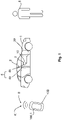
- a vehicle 1 is shown schematically in a side view.
- a device 100 provided externally to the vehicle 1 (that is, external to the vehicle) is shown, which can be embodied, for example, as a mobile communication device and/or as a mobile ID transmitter.
- the vehicle-external device 100 is a smartphone or the like. This has the advantage that the vehicle-external device 100 can already have various interfaces for communication, in particular radio communication, with the vehicle 1 .
- a communication unit 100.1 can be provided as such an interface of the vehicle-external device 100, which is embodied, for example, as an NFC (Near Field Communication) unit.
- NFC Near Field Communication
- the communication unit 100.1 can be designed as an NFC interface and thus enable wireless (contactless) data and/or energy transmission.
- radio signals can be transmitted between the communication unit 100.1 and a communication device 10 of the vehicle, in particular at a frequency of 13.56 MHz.
- This has the advantage that a reliable and contactless (ie for example radio-based) communication between the communication device 10 of the vehicle 1 and the vehicle-external device 100 is possible.
- This communication is used, for example, to authenticate the vehicle-external device 100 on the vehicle 1, so that a user 8 can use the vehicle-external device 100 as an identifier for activating a safety-related function of the vehicle 1.
- the safety-relevant function can be, for example, unlocking the vehicle 1 or opening a tailgate or the like.
- At least one sensor 4 in particular a proximity sensor and/or optical sensor, is provided for this purpose.
- Examples are in figure 1 an optical sensor 4a in the area of a B-pillar 2 of the vehicle 1 and a capacitive sensor 4b in the area of a door handle 3 of a vehicle 1 are shown.
- a respective sensor 4 and/or the specified positions on the vehicle 1 are also suitable for arranging the communication device 10.
- B. can hold the door handle 3 or the sensor 4 to carry out the data and / or energy transmission D by means of communication.
- the communication device 10 can be electrically and/or wirelessly connected to vehicle electronics 30 of the vehicle 1 .
- vehicle electronics includes z. B. at least one control unit 30 of a security system of the vehicle 1. This allows the vehicle electronics 30 to receive and evaluate the data transmitted via the communication via the communication device 10. For example, a code transmitted by means of the communication is evaluated in this way in order to carry out the authentication.
- the communication device 10 can be designed as an active interface, in particular a radio interface, preferably an NFC interface.
- a radio interface preferably an NFC interface.
- the communication device actively emits a radio signal and/or a magnetic field or can generate and/or can carry out a connection-related data transmission (in particular in the sense of NFC communication) and/or uses an in-vehicle energy supply iE to operate the communication device 10, preferably an evaluation unit 10.1 of the communication device 10.
- a passive interface can be understood to mean that a transmission (e.g.
- the interface In passive mode the interface has the properties of a passive interface and in active mode the interface has the properties of an active interface.
- the communication device 10 can be operated in the active mode, in which the energy supply for the communication device 10 is provided inside the vehicle by the vehicle 1, in particular by a vehicle-side energy source 5 such as a vehicle battery.
- This vehicle-internal energy supply iE is advantageously made possible by the fact that the communication device 10 is electrically connected to an on-board network of the vehicle 1, the on-board network being fed with electrical energy by the vehicle-side energy source 5. In this case one can also speak of an active mode I.
- the vehicle 1, in particular the communication device 10 provision can be made for the vehicle 1, in particular the communication device 10, to be able to switch from an active mode I to a deep sleep mode II.
- This is useful, for example, when a longer downtime, e.g. B. due to a long-term transport of the vehicle 1 is required.
- the communication device 10 can be a polling system that emits a radio signal at regular intervals, the active mode I is Energy consumption may be too high for a longer vehicle standstill. It is therefore necessary to reduce and/or completely deactivate the energy consumption of the communication device 10 and/or other components of the vehicle 1, in particular the complete vehicle electronics 30, in deep sleep mode II.
- the energy supply from the vehicle's energy source 5 (ie the vehicle's internal energy supply iE) can therefore be completely or predominantly deactivated for the communication device 10 and/or for at least some of the vehicle electronics 30 .
- the communication device 10 and/or the (for example all) vehicle electronics 30 are completely switched off and/or run without energy in deep sleep mode II.
- the communication device 10 can be operated in the passive mode in deep sleep mode II, so that the operation of the communication device 10 is possible at least partially through external influences, such as a radio signal and/or an inductive coupling K.
- the communication device 10 can be operated in the deep sleep mode II or in the passive mode by a vehicle-external energy supply eE, ie for example by external influences such as the radio signal and/or the inductive coupling K.
- This operation in deep sleep mode II can be implemented in such a way that the communication device 10 starts a wake-up process.
- the communication device 10 is operated in such a way that the wake-up process is carried out.
- the wake-up process includes, for example, an activation of the vehicle's internal energy supply iE.
- the communication device 10 can be designed to activate a vehicle-internal energy supply iE of the communication device 10 by means of a vehicle-external energy supply eE on the communication device 10 .
- the vehicle-external device 100 it is also conceivable for the vehicle-external device 100 to be authenticated before the activation of the vehicle-internal energy supply during the wake-up process. This makes sense, for example, if the security for this activation is to be increased.
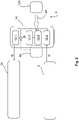
- a system according to the invention is shown as an example, which can provide the wake-up process, ie a change from deep sleep mode II to active mode I.
- a user 8 keeps the vehicle-external device 100 z. B. close to a communication element 10.2 of the communication device 10 of the vehicle 1.
- the communication element 10.2 is z. B. a coil and / or antenna, which according to the reception of radio signals, in particular the implementation of an inductive coupling K, allows. It can optionally be provided that this communication element 10.2 and/or another communication element of the communication device 10 is also used for data transmission D.
- the communication device 10 is advantageously operated in the passive mode for passive communication. Furthermore, it may be possible that the transmitted energy, which z. B. causes a current flow in the communication element 10.2, an energy storage element 10.3 is charged like a capacitor in the communication device 10. This enables the transmitted energy to be temporarily stored in order to operate the communication device 10.
- a processing unit 10.1 of the communication device 10 is operated in this case in order to send a wake-up signal to activate a switching device 40.
- the switching device 40 can be triggered when the vehicle-external energy supply eE is made available to the communication device 10 in order to carry out a change from the deep sleep mode II to the active mode I.
- This is made possible, for example, by the fact that an electronic switch of the vehicle 1, in particular the vehicle electronics 30, can be switched by the switching device 40.
- the switching device 40 can z. B. be part of the vehicle electronics 30 and / or part of the communication device 10 .
- a vehicle-internal energy supply iE is produced for this purpose. This is done e.g. B. by using a supply connection 10.4 of the communication device 10, via which the vehicle-side energy source 5 is connected to the communication device 10.
- active mode I the communication device 10, in particular the processing unit 10.1, can then be operated independently of the vehicle-external energy supply eE. In this way, in active mode I z. B. the data transmission D from the vehicle-external device 100 to the vehicle electronics 30 via the Communication device 10, in particular by the processing unit 10.1, performed.
- FIG 2 a schematic interconnection of the communication device 10 is shown, wherein in the active mode I the processing unit 10.1 is connected to the communication element 10.2 and the supply connection 10.4. This makes it clear that the operation of the communication device 10 is made possible by a vehicle-internal energy supply iE. In contrast, in deep sleep mode II, the processing unit 10.1 is connected to the energy storage element 10.3 and the communication element 10.2, so that the energy can be supplied externally to the vehicle.
- this representation is purely schematic and can be functionally enabled by different switching arrangements of the communication device 10, in particular by appropriate programming of the processing unit 10.1 and/or the switching device 40.
Landscapes
- Engineering & Computer Science (AREA)
- Theoretical Computer Science (AREA)
- Physics & Mathematics (AREA)
- General Physics & Mathematics (AREA)
- Mechanical Engineering (AREA)
- General Engineering & Computer Science (AREA)
- Computer Networks & Wireless Communication (AREA)
- Near-Field Transmission Systems (AREA)
Claims (15)
- Dispositif de communication (10) pour un véhicule (1) pour effectuer une transmission de données sans contact (D) entre une électronique de véhicule (30) et un appareil externe au véhicule (100) dans lequel le dispositif de communication (10) est conçu pour activer une alimentation en énergie (iE) interne au véhicule du dispositif de communication (10) au moyen d'une alimentation en énergie (eE) externe au véhicule sur le dispositif de communication (10), le dispositif de communication (10) étant conçu pour être relié électriquement, dans un mode actif (I), à une source d'énergie (5) du véhicule pour l'alimentation en énergie (iE) interne au véhicule, afin d'effectuer la transmission de données (D), la source d'énergie (5) du véhicule étant réalisée pour alimenter en énergie électrique des composants électriques du véhicule (1) via un réseau de bord.
- Dispositif de communication (10) selon la revendication 1,
caractérisé en ce que
un élément de communication (10.2) est prévu pour le couplage (K) sans contact avec l'appareil (100) externe au véhicule, afin de fournir, dans un mode de sommeil profond (II) du dispositif de communication (10), l'alimentation en énergie (eE) externe au véhicule par l'intermédiaire du couplage (K) sur le dispositif de communication (10). - Dispositif de communication (10) selon la revendication 1 ou 2,
caractérisé en ce que
le dispositif de communication (10) est conçu pour être connecté dans un mode de sommeil profond (II) à un élément de communication (10.2) du dispositif de communication (10) afin d'initier un passage dans le mode actif (I) dès que l'alimentation en énergie externe au véhicule (eE) est fournie. - Dispositif de communication (10) selon l'une quelconque des revendications précédentes,
caractérisé en ce que
dans un mode de sommeil profond (II), une alimentation en énergie du dispositif de communication (10) peut être établie indépendamment de l'alimentation en énergie (iE) interne au véhicule. - Dispositif de communication (10) selon l'une quelconque des revendications précédentes,
caractérisé en ce que
il est prévu un élément de communication (10.2) qui est relié par un premier câblage à un élément de stockage d'énergie (10.3), en particulier un condensateur, pour mettre à disposition l'alimentation en énergie externe au véhicule (eE) dans un mode de sommeil profond passif (II) pour réveiller l'électronique du véhicule (30), et par un deuxième câblage à un raccordement d'alimentation (10.4) pour le raccordement à une source d'énergie (5) du véhicule, afin de fournir l'alimentation en énergie (iE) interne au véhicule dans un mode actif (I) pour la transmission active de données (D) du dispositif de communication (10). - Dispositif de communication (10) selon l'une quelconque des revendications précédentes,
caractérisé en ce quele dispositif de communication (10) est réalisé sous la forme d'une interface NFC (10), l'interface NFC (10) pouvant être transférée d'un mode de sommeil profond (II) pour la communication passive à un mode actif (I) pour la communication active par la mise à disposition de l'alimentation en énergie (eE) externe au véhiculeet/ou en ce qu'il est prévu un élément de communication (10.2) qui est réalisé sous la forme d'une antenne (10.2) et/ou d'une bobine (10.2), afin de mettre à disposition la transmission d'énergie vers l'alimentation en énergie (eE) externe au véhicule et en particulier aussi la transmission de données (D) au moyen d'un couplage inductif et/ou en ce que le dispositif de communication (10) est réalisé pour être disposé dans une poignée de porte (3) et/ou dans un capteur (4) et/ou sur un montant B (2) du véhicule (1). - Système pour un véhicule (1), comprenant :- un dispositif de communication (10) selon l'une des revendications précédentes pour réaliser une transmission de données sans contact (D) entre une électronique de véhicule (30) et un appareil externe au véhicule (100),- un dispositif de commutation (40) pour passer d'un mode actif (I) à un mode de sommeil profond (II) du dispositif de communication (10),où dans le mode actif (I), une alimentation en énergie au moins du dispositif de communication (10) peut être établie à l'intérieur du véhicule et dans le mode de sommeil profond (II), l'alimentation en énergie peut être établie à l'extérieur du véhicule.
- Système selon l'une quelconque des revendications précédentes,
caractérisé en ce que
au moins une source d'énergie (5) du véhicule est prévue pour l'alimentation en énergie de l'électronique (30) du véhicule (1), en particulier de l'ensemble de celle-ci, l'alimentation en énergie par la source d'énergie (5) du véhicule pouvant être entièrement désactivée en mode de sommeil profond (II) et entièrement établie en mode actif (I), afin de réveiller le véhicule (1) par le passage du mode de sommeil profond (II) au mode actif (1). - Système selon l'une quelconque des revendications précédentes,
caractérisé en ce que
le dispositif de communication (10) est réalisé pour la communication avec l'appareil externe (100) sous la forme d'un appareil de communication mobile (100), de préférence un appareil de téléphonie mobile, de préférence des smartphones, un élément de communication (10.2) du dispositif de communication (10) étant réalisé pour la réception d'énergie sans contact, en particulier inductive, d'une unité de communication (100.1), en particulier d'une unité NFC active (100.1), de l'appareil (100) pour l'alimentation en énergie (eE) externe au véhicule. - Système selon l'une quelconque des revendications précédentes,
caractérisé en ce que
le dispositif de communication (10) est réalisé, en particulier uniquement en mode actif (I) ou aussi bien en mode actif (I) qu'en mode de sommeil profond (II) lorsque l'alimentation en énergie (eE) externe au véhicule est établie, pour effectuer une authentification de l'appareil externe (100) à l'aide de la transmission de données (D) et/ou en ce que le dispositif de communication (10) est réalisé dans le mode actif (I) pour émettre activement de manière répétée, de préférence au maximum à un intervalle de temps de 100 ms ou 200 ms ou 1 s ou 10 s, un signal de communication pour le couplage (K) avec l'appareil externe (100). - Système selon l'une quelconque des revendications précédentes,
caractérisé en ce que
l'électronique du véhicule (30) est prévue comme au moins un appareil de commande (30) et/ou un système de sécurité du véhicule (1), et présente une liaison de données sans fil ou par câble avec le dispositif de communication (10), une communication entre le dispositif de communication (10) et l'électronique du véhicule (30) pouvant être réalisée au moyen de la liaison de données par l'établissement de l'alimentation en énergie (eE) externe au véhicule en mode de sommeil profond (II). - Système selon l'une quelconque des revendications précédentes,
caractérisé en ce que
le mode de sommeil profond (II) est réalisé comme un mode de transport pour un transport de longue durée du véhicule (1). - Procédé pour faire fonctionner au moins un composant d'un véhicule (1) en économisant de l'énergie,
où les étapes suivantes sont effectuées :a) désactiver une alimentation en énergie (iE) interne au véhicule pour ledit au moins un composant afin de passer à un mode de sommeil profond (II),b) activer l'alimentation en énergie interne au véhicule (iE) pour ledit au moins un composant lorsqu'une alimentation en énergie externe au véhicule (eE) est fournie à un dispositif de communication (10) selon l'une des revendications précédentes du véhicule (1), afin de passer à un mode actif (I). - Procédé selon l'une quelconque des revendications précédentes,
caractérisé en ce que
selon l'étape b), l'alimentation en énergie (eE) externe au véhicule est mise à disposition sur le dispositif de communication (10) par le fait qu'un couplage (K), en particulier inductif, du dispositif de communication (10) est effectué avec un appareil externe (100) pour la transmission d'énergie, la transmission d'énergie étant adaptée à une activation et/ou à un fonctionnement d'un dispositif de commutation électronique (40), en particulier du dispositif de communication (10), par lequel le passage dans le mode actif (I) est initié. - Procédé selon l'une quelconque des revendications précédentes,
caractérisé en ce que
un système selon l'une des revendications précédentes est exploité.
Applications Claiming Priority (1)
| Application Number | Priority Date | Filing Date | Title |
|---|---|---|---|
| DE102018109506.6A DE102018109506A1 (de) | 2018-04-20 | 2018-04-20 | Kommunikationsvorrichtung für ein Fahrzeug zur Durchführung einer kontaktlosen Datenübertragung |
Publications (3)
| Publication Number | Publication Date |
|---|---|
| EP3581443A2 EP3581443A2 (fr) | 2019-12-18 |
| EP3581443A3 EP3581443A3 (fr) | 2020-01-15 |
| EP3581443B1 true EP3581443B1 (fr) | 2022-07-13 |
Family
ID=66217900
Family Applications (1)
| Application Number | Title | Priority Date | Filing Date |
|---|---|---|---|
| EP19169777.0A Active EP3581443B1 (fr) | 2018-04-20 | 2019-04-17 | Dispositif de communication pour un véhicule pour effectuer une transmission de données sans contact |
Country Status (2)
| Country | Link |
|---|---|
| EP (1) | EP3581443B1 (fr) |
| DE (1) | DE102018109506A1 (fr) |
Families Citing this family (1)
| Publication number | Priority date | Publication date | Assignee | Title |
|---|---|---|---|---|
| DE102024101286A1 (de) * | 2024-01-17 | 2025-07-17 | Bayerische Motoren Werke Aktiengesellschaft | Fortbewegungsmittel und Verfahren zur Versorgung eines Energiebordnetzes eines Fortbewegungsmittels |
Family Cites Families (7)
| Publication number | Priority date | Publication date | Assignee | Title |
|---|---|---|---|---|
| DE102004007721A1 (de) * | 2003-02-18 | 2004-08-26 | Marquardt Gmbh | Schließ- und/oder Steuerungssystem, insbesondere für ein Kraftfahrzeug |
| EP1564689A3 (fr) * | 2004-02-17 | 2006-04-26 | Huf Hülsbeck & Fürst GmbH & Co. KG | Procédé de commande de serrure comprenant un dispositif de secours pour déverrouiller et/ou verrouiller la serrure |
| DE102006002119A1 (de) * | 2005-01-19 | 2006-07-20 | Marquardt Gmbh | Schließsystem, insbesondere für ein Kraftfahrzeug |
| US8473153B1 (en) * | 2011-12-22 | 2013-06-25 | Honda Motor Co., Ltd. | Key fob battery life preservation system and method |
| DE102014104032A1 (de) * | 2014-03-24 | 2015-09-24 | Huf Hülsbeck & Fürst Gmbh & Co. Kg | Abgedichteter Identifikationsgeber |
| US9725069B2 (en) * | 2015-10-12 | 2017-08-08 | Ford Global Technologies, Llc | Keyless vehicle systems |
| DE102017214109B4 (de) * | 2017-08-11 | 2024-06-20 | Continental Automotive Technologies GmbH | Mobiler Identifikationsgeber |
-
2018
- 2018-04-20 DE DE102018109506.6A patent/DE102018109506A1/de not_active Withdrawn
-
2019
- 2019-04-17 EP EP19169777.0A patent/EP3581443B1/fr active Active
Also Published As
| Publication number | Publication date |
|---|---|
| EP3581443A2 (fr) | 2019-12-18 |
| DE102018109506A1 (de) | 2019-10-24 |
| EP3581443A3 (fr) | 2020-01-15 |
Similar Documents
| Publication | Publication Date | Title |
|---|---|---|
| EP3031676B1 (fr) | Dispositif pour un systeme de securite d'un vehicule | |
| DE112012002209B4 (de) | Am Fahrzeug angebrachte Batterieladestation einer persönlichen Vorrichtung und Betriebsverfahren zur Vermeidung von Interferenzen | |
| DE102013216099B4 (de) | System zum aktivieren eines fahrzeugs in einen schlüssel-ein- zustand | |
| DE102015102006A1 (de) | Elektronisches Schlüsselsystem | |
| DE102008039156A1 (de) | Verfahren, Vorrichtung und System zur Erfassung einer Berechtigung für ein Fahrzeug | |
| DE102014218213A1 (de) | Anordnung und Verfahren zum Detektieren der Annäherung eines Objektes | |
| DE102017203054B4 (de) | Zugangs- und Startsystem und Verfahren zur Zugangs- und Startverifizierung | |
| DE102017214109B4 (de) | Mobiler Identifikationsgeber | |
| DE102016215022B4 (de) | Verfahren zum Betreiben eines Zugangssystems eines Kraftfahrzeugs und Zugangssystem für ein Kraftfahrzeug | |
| DE102012002758A1 (de) | Verfahren und System zum Einstellen eines Kraftfahrzeugs aus der Ferne | |
| EP3581443B1 (fr) | Dispositif de communication pour un véhicule pour effectuer une transmission de données sans contact | |
| EP2814700B1 (fr) | Capteur d'identification portatif pour système d'accès passif à un véhicule automobile et procédé économe en énergie permettant de faire fonctionner le capteur d'identification | |
| EP3636495A1 (fr) | Système pour un véhicule | |
| DE102014221933B4 (de) | Verhindern einer Funktionsstörung eines schlüssellosen Zugangsberechtigungssystems eines Kraftfahrzeugs durch das Wechselfeld einer induktiven Ladestation | |
| EP3424767B1 (fr) | Véhicule automobile | |
| WO2023072648A1 (fr) | Dispositif et procédé de commande d'un processus de charge et système de charge automatique d'une batterie de traction | |
| DE102014216987A1 (de) | Schlüsselloses System und mobile Vorrichtung | |
| DE102013207495A1 (de) | Handhabe für einen beweglichen Teil eines Kraftfahrzeugs und Verfahren zur Übertragung von Daten in einem Kraftfahrzeug | |
| DE102010052099A1 (de) | Verfahren zum Teilwecken eines Kraftfahrzeugbordnetzes | |
| DE102016222217B4 (de) | Induktive Ladestation und Verfahren zum Steuern einer induktiven Ladestation | |
| EP3651127A1 (fr) | Module d'adaptateur pour un véhicule permettant d'activer une fonction relative à la sécurité du véhicule | |
| EP2825424B1 (fr) | Système de fermeture, en particulier pour un véhicule à moteur | |
| DE102016218618A1 (de) | Vorrichtung und Verfahren zur Zugangs- und Startverifizierung in einem Fahrzeug | |
| DE102014100581B4 (de) | Verfahren zum Betrieb eines mobilen Kommunikationsgerätes und eines Fahrzeuges | |
| EP3637377A1 (fr) | Système pour un système d'accès passif d'un véhicule |
Legal Events
| Date | Code | Title | Description |
|---|---|---|---|
| PUAI | Public reference made under article 153(3) epc to a published international application that has entered the european phase |
Free format text: ORIGINAL CODE: 0009012 |
|
| STAA | Information on the status of an ep patent application or granted ep patent |
Free format text: STATUS: THE APPLICATION HAS BEEN PUBLISHED |
|
| PUAL | Search report despatched |
Free format text: ORIGINAL CODE: 0009013 |
|
| AK | Designated contracting states |
Kind code of ref document: A2 Designated state(s): AL AT BE BG CH CY CZ DE DK EE ES FI FR GB GR HR HU IE IS IT LI LT LU LV MC MK MT NL NO PL PT RO RS SE SI SK SM TR |
|
| AX | Request for extension of the european patent |
Extension state: BA ME |
|
| AK | Designated contracting states |
Kind code of ref document: A3 Designated state(s): AL AT BE BG CH CY CZ DE DK EE ES FI FR GB GR HR HU IE IS IT LI LT LU LV MC MK MT NL NO PL PT RO RS SE SI SK SM TR |
|
| AX | Request for extension of the european patent |
Extension state: BA ME |
|
| RIC1 | Information provided on ipc code assigned before grant |
Ipc: B60R 25/40 20130101AFI20191210BHEP Ipc: G07C 9/00 20060101ALI20191210BHEP Ipc: E05B 81/82 20140101ALI20191210BHEP |
|
| STAA | Information on the status of an ep patent application or granted ep patent |
Free format text: STATUS: REQUEST FOR EXAMINATION WAS MADE |
|
| 17P | Request for examination filed |
Effective date: 20200715 |
|
| RBV | Designated contracting states (corrected) |
Designated state(s): AL AT BE BG CH CY CZ DE DK EE ES FI FR GB GR HR HU IE IS IT LI LT LU LV MC MK MT NL NO PL PT RO RS SE SI SK SM TR |
|
| RIC1 | Information provided on ipc code assigned before grant |
Ipc: G07C 9/00 20200101ALI20211222BHEP Ipc: E05B 81/82 20140101ALI20211222BHEP Ipc: B60R 25/40 20130101AFI20211222BHEP |
|
| GRAP | Despatch of communication of intention to grant a patent |
Free format text: ORIGINAL CODE: EPIDOSNIGR1 |
|
| STAA | Information on the status of an ep patent application or granted ep patent |
Free format text: STATUS: GRANT OF PATENT IS INTENDED |
|
| INTG | Intention to grant announced |
Effective date: 20220201 |
|
| GRAS | Grant fee paid |
Free format text: ORIGINAL CODE: EPIDOSNIGR3 |
|
| GRAA | (expected) grant |
Free format text: ORIGINAL CODE: 0009210 |
|
| STAA | Information on the status of an ep patent application or granted ep patent |
Free format text: STATUS: THE PATENT HAS BEEN GRANTED |
|
| AK | Designated contracting states |
Kind code of ref document: B1 Designated state(s): AL AT BE BG CH CY CZ DE DK EE ES FI FR GB GR HR HU IE IS IT LI LT LU LV MC MK MT NL NO PL PT RO RS SE SI SK SM TR |
|
| REG | Reference to a national code |
Ref country code: CH Ref legal event code: EP |
|
| REG | Reference to a national code |
Ref country code: DE Ref legal event code: R096 Ref document number: 502019004937 Country of ref document: DE |
|
| REG | Reference to a national code |
Ref country code: AT Ref legal event code: REF Ref document number: 1504125 Country of ref document: AT Kind code of ref document: T Effective date: 20220815 |
|
| REG | Reference to a national code |
Ref country code: IE Ref legal event code: FG4D Free format text: LANGUAGE OF EP DOCUMENT: GERMAN |
|
| REG | Reference to a national code |
Ref country code: LT Ref legal event code: MG9D |
|
| REG | Reference to a national code |
Ref country code: NL Ref legal event code: MP Effective date: 20220713 |
|
| PG25 | Lapsed in a contracting state [announced via postgrant information from national office to epo] |
Ref country code: SE Free format text: LAPSE BECAUSE OF FAILURE TO SUBMIT A TRANSLATION OF THE DESCRIPTION OR TO PAY THE FEE WITHIN THE PRESCRIBED TIME-LIMIT Effective date: 20220713 Ref country code: RS Free format text: LAPSE BECAUSE OF FAILURE TO SUBMIT A TRANSLATION OF THE DESCRIPTION OR TO PAY THE FEE WITHIN THE PRESCRIBED TIME-LIMIT Effective date: 20220713 Ref country code: PT Free format text: LAPSE BECAUSE OF FAILURE TO SUBMIT A TRANSLATION OF THE DESCRIPTION OR TO PAY THE FEE WITHIN THE PRESCRIBED TIME-LIMIT Effective date: 20221114 Ref country code: NO Free format text: LAPSE BECAUSE OF FAILURE TO SUBMIT A TRANSLATION OF THE DESCRIPTION OR TO PAY THE FEE WITHIN THE PRESCRIBED TIME-LIMIT Effective date: 20221013 Ref country code: NL Free format text: LAPSE BECAUSE OF FAILURE TO SUBMIT A TRANSLATION OF THE DESCRIPTION OR TO PAY THE FEE WITHIN THE PRESCRIBED TIME-LIMIT Effective date: 20220713 Ref country code: LV Free format text: LAPSE BECAUSE OF FAILURE TO SUBMIT A TRANSLATION OF THE DESCRIPTION OR TO PAY THE FEE WITHIN THE PRESCRIBED TIME-LIMIT Effective date: 20220713 Ref country code: LT Free format text: LAPSE BECAUSE OF FAILURE TO SUBMIT A TRANSLATION OF THE DESCRIPTION OR TO PAY THE FEE WITHIN THE PRESCRIBED TIME-LIMIT Effective date: 20220713 Ref country code: FI Free format text: LAPSE BECAUSE OF FAILURE TO SUBMIT A TRANSLATION OF THE DESCRIPTION OR TO PAY THE FEE WITHIN THE PRESCRIBED TIME-LIMIT Effective date: 20220713 Ref country code: ES Free format text: LAPSE BECAUSE OF FAILURE TO SUBMIT A TRANSLATION OF THE DESCRIPTION OR TO PAY THE FEE WITHIN THE PRESCRIBED TIME-LIMIT Effective date: 20220713 |
|
| PG25 | Lapsed in a contracting state [announced via postgrant information from national office to epo] |
Ref country code: PL Free format text: LAPSE BECAUSE OF FAILURE TO SUBMIT A TRANSLATION OF THE DESCRIPTION OR TO PAY THE FEE WITHIN THE PRESCRIBED TIME-LIMIT Effective date: 20220713 Ref country code: IS Free format text: LAPSE BECAUSE OF FAILURE TO SUBMIT A TRANSLATION OF THE DESCRIPTION OR TO PAY THE FEE WITHIN THE PRESCRIBED TIME-LIMIT Effective date: 20221113 Ref country code: HR Free format text: LAPSE BECAUSE OF FAILURE TO SUBMIT A TRANSLATION OF THE DESCRIPTION OR TO PAY THE FEE WITHIN THE PRESCRIBED TIME-LIMIT Effective date: 20220713 Ref country code: GR Free format text: LAPSE BECAUSE OF FAILURE TO SUBMIT A TRANSLATION OF THE DESCRIPTION OR TO PAY THE FEE WITHIN THE PRESCRIBED TIME-LIMIT Effective date: 20221014 |
|
| REG | Reference to a national code |
Ref country code: DE Ref legal event code: R097 Ref document number: 502019004937 Country of ref document: DE |
|
| PG25 | Lapsed in a contracting state [announced via postgrant information from national office to epo] |
Ref country code: SM Free format text: LAPSE BECAUSE OF FAILURE TO SUBMIT A TRANSLATION OF THE DESCRIPTION OR TO PAY THE FEE WITHIN THE PRESCRIBED TIME-LIMIT Effective date: 20220713 Ref country code: RO Free format text: LAPSE BECAUSE OF FAILURE TO SUBMIT A TRANSLATION OF THE DESCRIPTION OR TO PAY THE FEE WITHIN THE PRESCRIBED TIME-LIMIT Effective date: 20220713 Ref country code: DK Free format text: LAPSE BECAUSE OF FAILURE TO SUBMIT A TRANSLATION OF THE DESCRIPTION OR TO PAY THE FEE WITHIN THE PRESCRIBED TIME-LIMIT Effective date: 20220713 Ref country code: CZ Free format text: LAPSE BECAUSE OF FAILURE TO SUBMIT A TRANSLATION OF THE DESCRIPTION OR TO PAY THE FEE WITHIN THE PRESCRIBED TIME-LIMIT Effective date: 20220713 |
|
| PLBE | No opposition filed within time limit |
Free format text: ORIGINAL CODE: 0009261 |
|
| STAA | Information on the status of an ep patent application or granted ep patent |
Free format text: STATUS: NO OPPOSITION FILED WITHIN TIME LIMIT |
|
| PG25 | Lapsed in a contracting state [announced via postgrant information from national office to epo] |
Ref country code: SK Free format text: LAPSE BECAUSE OF FAILURE TO SUBMIT A TRANSLATION OF THE DESCRIPTION OR TO PAY THE FEE WITHIN THE PRESCRIBED TIME-LIMIT Effective date: 20220713 Ref country code: EE Free format text: LAPSE BECAUSE OF FAILURE TO SUBMIT A TRANSLATION OF THE DESCRIPTION OR TO PAY THE FEE WITHIN THE PRESCRIBED TIME-LIMIT Effective date: 20220713 |
|
| P01 | Opt-out of the competence of the unified patent court (upc) registered |
Effective date: 20230427 |
|
| 26N | No opposition filed |
Effective date: 20230414 |
|
| PG25 | Lapsed in a contracting state [announced via postgrant information from national office to epo] |
Ref country code: AL Free format text: LAPSE BECAUSE OF FAILURE TO SUBMIT A TRANSLATION OF THE DESCRIPTION OR TO PAY THE FEE WITHIN THE PRESCRIBED TIME-LIMIT Effective date: 20220713 |
|
| PG25 | Lapsed in a contracting state [announced via postgrant information from national office to epo] |
Ref country code: SI Free format text: LAPSE BECAUSE OF FAILURE TO SUBMIT A TRANSLATION OF THE DESCRIPTION OR TO PAY THE FEE WITHIN THE PRESCRIBED TIME-LIMIT Effective date: 20220713 |
|
| REG | Reference to a national code |
Ref country code: CH Ref legal event code: PL |
|
| GBPC | Gb: european patent ceased through non-payment of renewal fee |
Effective date: 20230417 |
|
| PG25 | Lapsed in a contracting state [announced via postgrant information from national office to epo] |
Ref country code: LU Free format text: LAPSE BECAUSE OF NON-PAYMENT OF DUE FEES Effective date: 20230417 |
|
| REG | Reference to a national code |
Ref country code: BE Ref legal event code: MM Effective date: 20230430 |
|
| PG25 | Lapsed in a contracting state [announced via postgrant information from national office to epo] |
Ref country code: MC Free format text: LAPSE BECAUSE OF FAILURE TO SUBMIT A TRANSLATION OF THE DESCRIPTION OR TO PAY THE FEE WITHIN THE PRESCRIBED TIME-LIMIT Effective date: 20220713 |
|
| PG25 | Lapsed in a contracting state [announced via postgrant information from national office to epo] |
Ref country code: GB Free format text: LAPSE BECAUSE OF NON-PAYMENT OF DUE FEES Effective date: 20230417 |
|
| PG25 | Lapsed in a contracting state [announced via postgrant information from national office to epo] |
Ref country code: MC Free format text: LAPSE BECAUSE OF FAILURE TO SUBMIT A TRANSLATION OF THE DESCRIPTION OR TO PAY THE FEE WITHIN THE PRESCRIBED TIME-LIMIT Effective date: 20220713 Ref country code: LI Free format text: LAPSE BECAUSE OF NON-PAYMENT OF DUE FEES Effective date: 20230430 Ref country code: IT Free format text: LAPSE BECAUSE OF FAILURE TO SUBMIT A TRANSLATION OF THE DESCRIPTION OR TO PAY THE FEE WITHIN THE PRESCRIBED TIME-LIMIT Effective date: 20220713 Ref country code: GB Free format text: LAPSE BECAUSE OF NON-PAYMENT OF DUE FEES Effective date: 20230417 Ref country code: FR Free format text: LAPSE BECAUSE OF NON-PAYMENT OF DUE FEES Effective date: 20230430 Ref country code: CH Free format text: LAPSE BECAUSE OF NON-PAYMENT OF DUE FEES Effective date: 20230430 |
|
| REG | Reference to a national code |
Ref country code: IE Ref legal event code: MM4A |
|
| PG25 | Lapsed in a contracting state [announced via postgrant information from national office to epo] |
Ref country code: BE Free format text: LAPSE BECAUSE OF NON-PAYMENT OF DUE FEES Effective date: 20230430 |
|
| PG25 | Lapsed in a contracting state [announced via postgrant information from national office to epo] |
Ref country code: IE Free format text: LAPSE BECAUSE OF NON-PAYMENT OF DUE FEES Effective date: 20230417 |
|
| PG25 | Lapsed in a contracting state [announced via postgrant information from national office to epo] |
Ref country code: IE Free format text: LAPSE BECAUSE OF NON-PAYMENT OF DUE FEES Effective date: 20230417 |
|
| PG25 | Lapsed in a contracting state [announced via postgrant information from national office to epo] |
Ref country code: BG Free format text: LAPSE BECAUSE OF FAILURE TO SUBMIT A TRANSLATION OF THE DESCRIPTION OR TO PAY THE FEE WITHIN THE PRESCRIBED TIME-LIMIT Effective date: 20220713 |
|
| PG25 | Lapsed in a contracting state [announced via postgrant information from national office to epo] |
Ref country code: BG Free format text: LAPSE BECAUSE OF FAILURE TO SUBMIT A TRANSLATION OF THE DESCRIPTION OR TO PAY THE FEE WITHIN THE PRESCRIBED TIME-LIMIT Effective date: 20220713 |
|
| REG | Reference to a national code |
Ref country code: AT Ref legal event code: MM01 Ref document number: 1504125 Country of ref document: AT Kind code of ref document: T Effective date: 20240417 |
|
| PGFP | Annual fee paid to national office [announced via postgrant information from national office to epo] |
Ref country code: DE Payment date: 20250430 Year of fee payment: 7 |
|
| PG25 | Lapsed in a contracting state [announced via postgrant information from national office to epo] |
Ref country code: AT Free format text: LAPSE BECAUSE OF NON-PAYMENT OF DUE FEES Effective date: 20240417 |
|
| PG25 | Lapsed in a contracting state [announced via postgrant information from national office to epo] |
Ref country code: CY Free format text: LAPSE BECAUSE OF FAILURE TO SUBMIT A TRANSLATION OF THE DESCRIPTION OR TO PAY THE FEE WITHIN THE PRESCRIBED TIME-LIMIT; INVALID AB INITIO Effective date: 20190417 |
|
| PG25 | Lapsed in a contracting state [announced via postgrant information from national office to epo] |
Ref country code: HU Free format text: LAPSE BECAUSE OF FAILURE TO SUBMIT A TRANSLATION OF THE DESCRIPTION OR TO PAY THE FEE WITHIN THE PRESCRIBED TIME-LIMIT; INVALID AB INITIO Effective date: 20190417 |
|
| PG25 | Lapsed in a contracting state [announced via postgrant information from national office to epo] |
Ref country code: TR Free format text: LAPSE BECAUSE OF FAILURE TO SUBMIT A TRANSLATION OF THE DESCRIPTION OR TO PAY THE FEE WITHIN THE PRESCRIBED TIME-LIMIT Effective date: 20220713 |
|
| PGFP | Annual fee paid to national office [announced via postgrant information from national office to epo] |
Ref country code: AT Payment date: 20260410 Year of fee payment: 5 |