EP3587763A1 - Procédé de régulation d'une machine à énergie fluidique et dispositif de régulation, en particulier destiné à la mise en ouvre dudit procédé - Google Patents
Procédé de régulation d'une machine à énergie fluidique et dispositif de régulation, en particulier destiné à la mise en ouvre dudit procédé Download PDFInfo
- Publication number
- EP3587763A1 EP3587763A1 EP19183207.0A EP19183207A EP3587763A1 EP 3587763 A1 EP3587763 A1 EP 3587763A1 EP 19183207 A EP19183207 A EP 19183207A EP 3587763 A1 EP3587763 A1 EP 3587763A1
- Authority
- EP
- European Patent Office
- Prior art keywords
- speed
- torque
- control
- generator
- sub
- Prior art date
- Legal status (The legal status is an assumption and is not a legal conclusion. Google has not performed a legal analysis and makes no representation as to the accuracy of the status listed.)
- Granted
Links
Images

Classifications
-
- F—MECHANICAL ENGINEERING; LIGHTING; HEATING; WEAPONS; BLASTING
- F02—COMBUSTION ENGINES; HOT-GAS OR COMBUSTION-PRODUCT ENGINE PLANTS
- F02B—INTERNAL-COMBUSTION PISTON ENGINES; COMBUSTION ENGINES IN GENERAL
- F02B63/00—Adaptations of engines for driving pumps, hand-held tools or electric generators; Portable combinations of engines with engine-driven devices
- F02B63/04—Adaptations of engines for driving pumps, hand-held tools or electric generators; Portable combinations of engines with engine-driven devices for electric generators
-
- F—MECHANICAL ENGINEERING; LIGHTING; HEATING; WEAPONS; BLASTING
- F02—COMBUSTION ENGINES; HOT-GAS OR COMBUSTION-PRODUCT ENGINE PLANTS
- F02D—CONTROLLING COMBUSTION ENGINES
- F02D29/00—Controlling engines, such controlling being peculiar to the devices driven thereby, the devices being other than parts or accessories essential to engine operation, e.g. controlling of engines by signals external thereto
- F02D29/06—Controlling engines, such controlling being peculiar to the devices driven thereby, the devices being other than parts or accessories essential to engine operation, e.g. controlling of engines by signals external thereto peculiar to engines driving electric generators
-
- F—MECHANICAL ENGINEERING; LIGHTING; HEATING; WEAPONS; BLASTING
- F02—COMBUSTION ENGINES; HOT-GAS OR COMBUSTION-PRODUCT ENGINE PLANTS
- F02D—CONTROLLING COMBUSTION ENGINES
- F02D41/00—Electrical control of supply of combustible mixture or its constituents
- F02D41/0025—Controlling engines characterised by use of non-liquid fuels, pluralities of fuels, or non-fuel substances added to the combustible mixtures
- F02D41/0027—Controlling engines characterised by use of non-liquid fuels, pluralities of fuels, or non-fuel substances added to the combustible mixtures the fuel being gaseous
-
- F—MECHANICAL ENGINEERING; LIGHTING; HEATING; WEAPONS; BLASTING
- F02—COMBUSTION ENGINES; HOT-GAS OR COMBUSTION-PRODUCT ENGINE PLANTS
- F02M—SUPPLYING COMBUSTION ENGINES IN GENERAL WITH COMBUSTIBLE MIXTURES OR CONSTITUENTS THEREOF
- F02M21/00—Apparatus for supplying engines with non-liquid fuels, e.g. gaseous fuels stored in liquid form
- F02M21/02—Apparatus for supplying engines with non-liquid fuels, e.g. gaseous fuels stored in liquid form for gaseous fuels
-
- H—ELECTRICITY
- H02—GENERATION; CONVERSION OR DISTRIBUTION OF ELECTRIC POWER
- H02J—ELECTRIC POWER NETWORKS; CIRCUIT ARRANGEMENTS OR SYSTEMS FOR SUPPLYING OR DISTRIBUTING ELECTRIC POWER; SYSTEMS FOR STORING ELECTRIC ENERGY
- H02J3/00—Circuit arrangements for AC mains or AC distribution networks
- H02J3/38—Arrangements for feeding a single network from two or more generators or sources in parallel; Arrangements for feeding already energised networks from additional generators or sources in parallel
- H02J3/40—Synchronisation of generators for connection to a network or to another generator
-
- H—ELECTRICITY
- H02—GENERATION; CONVERSION OR DISTRIBUTION OF ELECTRIC POWER
- H02P—CONTROL OR REGULATION OF ELECTRIC MOTORS, ELECTRIC GENERATORS OR DYNAMO-ELECTRIC CONVERTERS; CONTROLLING TRANSFORMERS, REACTORS OR CHOKE COILS
- H02P23/00—Arrangements or methods for the control of AC motors characterised by a control method other than vector control
- H02P23/0077—Characterised by the use of a particular software algorithm
-
- H—ELECTRICITY
- H02—GENERATION; CONVERSION OR DISTRIBUTION OF ELECTRIC POWER
- H02P—CONTROL OR REGULATION OF ELECTRIC MOTORS, ELECTRIC GENERATORS OR DYNAMO-ELECTRIC CONVERTERS; CONTROLLING TRANSFORMERS, REACTORS OR CHOKE COILS
- H02P9/00—Arrangements for controlling electric generators for the purpose of obtaining a desired output
- H02P9/04—Control effected upon non-electric prime mover and dependent upon electric output value of the generator
-
- F—MECHANICAL ENGINEERING; LIGHTING; HEATING; WEAPONS; BLASTING
- F02—COMBUSTION ENGINES; HOT-GAS OR COMBUSTION-PRODUCT ENGINE PLANTS
- F02B—INTERNAL-COMBUSTION PISTON ENGINES; COMBUSTION ENGINES IN GENERAL
- F02B43/00—Engines characterised by operating on gaseous fuels; Plants including such engines
-
- F—MECHANICAL ENGINEERING; LIGHTING; HEATING; WEAPONS; BLASTING
- F02—COMBUSTION ENGINES; HOT-GAS OR COMBUSTION-PRODUCT ENGINE PLANTS
- F02D—CONTROLLING COMBUSTION ENGINES
- F02D2250/00—Engine control related to specific problems or objectives
- F02D2250/18—Control of the engine output torque
-
- F—MECHANICAL ENGINEERING; LIGHTING; HEATING; WEAPONS; BLASTING
- F02—COMBUSTION ENGINES; HOT-GAS OR COMBUSTION-PRODUCT ENGINE PLANTS
- F02D—CONTROLLING COMBUSTION ENGINES
- F02D2250/00—Engine control related to specific problems or objectives
- F02D2250/18—Control of the engine output torque
- F02D2250/24—Control of the engine output torque by using an external load, e.g. a generator
-
- H—ELECTRICITY
- H02—GENERATION; CONVERSION OR DISTRIBUTION OF ELECTRIC POWER
- H02P—CONTROL OR REGULATION OF ELECTRIC MOTORS, ELECTRIC GENERATORS OR DYNAMO-ELECTRIC CONVERTERS; CONTROLLING TRANSFORMERS, REACTORS OR CHOKE COILS
- H02P23/00—Arrangements or methods for the control of AC motors characterised by a control method other than vector control
- H02P23/14—Estimation or adaptation of motor parameters, e.g. rotor time constant, flux, speed, current or voltage
-
- Y—GENERAL TAGGING OF NEW TECHNOLOGICAL DEVELOPMENTS; GENERAL TAGGING OF CROSS-SECTIONAL TECHNOLOGIES SPANNING OVER SEVERAL SECTIONS OF THE IPC; TECHNICAL SUBJECTS COVERED BY FORMER USPC CROSS-REFERENCE ART COLLECTIONS [XRACs] AND DIGESTS
- Y02—TECHNOLOGIES OR APPLICATIONS FOR MITIGATION OR ADAPTATION AGAINST CLIMATE CHANGE
- Y02T—CLIMATE CHANGE MITIGATION TECHNOLOGIES RELATED TO TRANSPORTATION
- Y02T10/00—Road transport of goods or passengers
- Y02T10/10—Internal combustion engine [ICE] based vehicles
- Y02T10/30—Use of alternative fuels, e.g. biofuels
Definitions
- the invention relates to a method for regulating a fluid energy machine and a regulating arrangement which is used in particular to carry out the method.
- the fluid energy machine is preferably used for a power unit for feeding energy obtained in particular from gaseous fuels such as biogas into an electrical power supply network.
- An electrical power supply network in the sense of the present invention is a power network that serves to supply consumers with electrical energy in electrical power engineering.
- a power network is a network of electrical power lines, in particular overhead lines and underground cables, which in particular connect facilities such as power plants and other energy converters, for example wind energy and photovoltaic systems, switchgear and transformer stations connected to them and the consumers.
- the electrical power supply network can be designed as a so-called interconnected network, which is generally composed of large, spatially adjacent and electrically connected power networks, which comprise a large number of power plants and consumers.
- the electrical power supply network can also be configured as a so-called island network, that is to say as a locally delimited power network that supplies a spatially narrow area and has no direct electrical connection to other power networks.
- Electricity generators for feeding energy into an electrical power supply network are known, in which the energy is obtained from gaseous fuels.
- gaseous fuels For example, biogas, a combustible gas that is produced by fermentation of biomass, is suitable as a gaseous fuel.
- Biogas is usually produced in biogas plants, which are used to ferment biological waste and renewable raw materials.
- Such a power unit usually comprises a generator, which is designed in particular as a synchronous generator, and a fluid energy machine, which is generally designed as an internal combustion engine, and which drives the generator.
- the internal combustion engine converts the chemical energy of the fuel, for example a gas such as biogas, wood gas, mine gas, natural gas or propane, into kinetic energy, with which the generator is then driven.
- the generator converts the kinetic energy into electrical energy, which is fed into the energy supply network.
- the generator of the power unit is a synchronous generator, the generator must be synchronized with the electrical power supply network before energy can be fed into the electrical power supply network from the power unit.
- a control variable such as the speed or the torque
- a single control loop is usually controlled via a single control loop.
- An example of this is from EP 2 315 946 B1 known.
- a control loop basically consists of a controlled system, an actuator, a controller and a feedback, which are connected to each other in a closed loop.
- the controlled system is controlled by the controller via the actuator.
- the control of the controller itself is based on a controlled variable which is fed back from the controlled system.
- the controller can always readjust the controlled system based on a current output value of the controlled system.
- the controller With a single control loop, the controller usually controls the entire value range of a control variable. Control loops that can regulate over comparatively wide value ranges, and optimally in a reasonable time, have comparatively high time constants.
- the time constant of the control loop shows the delay times in the control loop. If a control loop has long delay times, the control loop tends to run through it when controlling to a predetermined value of the controlled variable. This effect is called overshoot. The controller must then Reduce the controlled variable again. Overshoot is therefore to be understood to mean that, in a control loop, due to unavoidable delay times, which are represented by the time constant, the target value is passed when regulating the controlled variable and the control loop thus overshoots. The target value can only be achieved in a stable manner by means of regulation that is becoming more and more precise. Undershoot can also occur in an upside-down control loop.
- Control loops with comparatively high time constants, which often occur with mechanical manipulated variables, are characterized by particularly high overshoot.
- the regulation of the fluid energy machines is comparatively complex.
- WO 2017/137227 A1 is known a power plant with a gas turbine and a generator, in which the gas turbine is accelerated with the help of an electric motor.
- the engine is only in operation during the start and, if necessary, during the cooling phase, in the so-called rotating operation, of the gas turbine. During this period, it is supplied by a converter, otherwise it only rotates when idling.
- a method for operating a wind turbine is disclosed DE 10 2006 040 929 A1 , A synchronous generator is synchronized with the grid before the wind turbine is switched on.
- the generator shaft is driven by a motor via a superposition gear. The speed is increased until the nominal speed of the synchronous generator is reached.
- the invention is based on the object of making available a method for regulating a fluid energy machine and a regulating arrangement which is particularly suitable for carrying out the method, which enable comparatively fast and precise regulation.
- the method according to the invention for regulating a fluid energy machine by means of which energy is converted into mechanical work and which generates a rotary movement with a first torque and which is connected to an output shaft to which a second torque is applied at a speed, comprises the following method steps: Controlling the first torque in a first method step by means of a control device such that the second torque is set to a predetermined intermediate torque at an intermediate speed, the fluid energy machine and the control device forming a first control loop with a first time constant;
- control system is to be understood as the moment of inertia of the fluid energy machine.
- Any load coupled to the fluid energy machine for example a generator, contributes to the moment of inertia, that is to say determines the characteristic of the controlled system.
- the fluid energy machine In order to regulate the fluid energy machine to the target speed, the fluid energy machine is regulated by actuators, which in turn are regulated by a regulator, that is to say the regulating device or the auxiliary unit.
- the current speed of the output shaft which can be part of the fluid energy machine or a separate component, is available to the controller.
- the first or the second control loop acts.
- the first torque are the controlled variables the fluid energy machine in the first control loop and the speed of the output shaft in the second control loop.
- the regulation process is to be understood as the regulation of the fluid energy machine if the fluid energy machine is regulated from a current speed to a previously determined target speed and the overshoot is regulated until the fluid energy machine keeps the target speed stable.
- the second control loop regulates the speed from the intermediate speed to the target speed faster than the first control loop could achieve to the same extent via the control variable of the first torque. In this way, not only a more reliable, but also a faster and more precise control is made possible.
- the control device expediently functions as an actuator for the first control circuit, the control device preferably comprising a throttle as an actuator.
- a throttle is particularly well suited as an actuator because it represents a simple, efficient design of an actuator.
- the control loop which is based in particular on the throttle and the fluid energy machine, has a comparatively high first time constant, which has a disadvantageous effect in the case of precise control, in particular when regulating the fluid energy machine.
- the auxiliary unit advantageously functions as an actuator for the second control loop.
- the auxiliary unit and the control device can be designed as a common device which comprises the two different actuators.
- the first torque is preferably regulated exclusively by means of the control device and in the second method step the speed is regulated exclusively by means of the auxiliary unit.
- the first and the second control loop differ mainly in the different time constants.
- a control loop with a high time constant has advantages for rough control of large value ranges of the controlled variable, but is disadvantageous for precise controls due to the high overshoot.
- a control loop with a low time constant is characterized by a particularly precise control, but is disadvantageous when controlling large ranges of values of the controlled variable. It has therefore proven to be advantageous to control the speed via the first torque in the first control loop exclusively by means of the control device in order to take advantage of large value ranges of the controlled variable, and to control the speed in the second control loop exclusively by means of the auxiliary unit in order to to take advantage of precise regulation.
- the intermediate speed can be within a tolerance band around the target speed. In general, however, this does not have to be kept stable, but only to be achieved selectively. It has proven to be expedient if the intermediate speed is in a range between 60% and 140% of the target speed.
- the intermediate speed is preferably in a range between 80% and 120% of the target speed. For example, if the target speed is approximately 1500 revolutions per minute (rpm), the intermediate speed can range between 900 rpm (60%) and 2100 rpm (140%).
- the intermediate speed preferably ranges between 1200 rpm (80%) and 1800 rpm (120%).
- the control arrangement is used in particular to carry out the method and comprises a fluid energy machine for converting energy into mechanical work, which generates a rotary movement with a first torque and which is connected to an output shaft, to which a second torque is applied at a speed.
- the control arrangement further comprises a control device for controlling the first torque in such a way that the second torque is set to a predetermined intermediate torque at an intermediate speed.
- the fluid energy machine and the control device form a first control loop with a first time constant.
- the control arrangement also includes an auxiliary unit for controlling the speed of the output shaft in such a way that the speed is set from the intermediate speed to a predetermined target speed. A moment of inertia resulting on the output shaft and the auxiliary unit form a second control loop with a second time constant.
- the second control loop acts directly on the rotational movement of the output shaft without directly influencing the fluid energy machine.
- the time constant no longer has to be taken into account as the control time constant of the fluid energy machine, but only the moment of inertia, which results in particular from the fluid energy machine and the connected load, for example a generator, on the output shaft as a time constant.
- Factors for the control time constant of the fluid energy machine are, for example, pressures, volume flows, other controllers of the fluid energy machine or dimensions of parts of the fluid energy machine that influence the control. This second time constant is significantly less than the first time constant.
- the fluid energy machine is advantageously designed as a heat engine, in particular an internal combustion engine, steam engine, steam turbine or gas turbine, or as a hydraulic motor.
- the auxiliary unit is advantageously designed as an electric motor, in particular as a DC motor or as an asynchronous motor or as a synchronous reluctance motor.
- the auxiliary unit is designed as a mechanical braking device, which is preferably arranged on the output shaft, in order to reduce the speed of the output shaft, in particular by converting rotational energy into heat.
- the control device advantageously functions as an actuator for the first control circuit, the control device preferably having a throttle as an actuator.
- the auxiliary unit advantageously functions as an actuator for the second control loop.
- the control arrangement advantageously comprises a generator, in particular a synchronous generator, the fluid energy machine preferably driving the generator. This converts the chemical energy of the fluid energy machine into kinetic energy that drives the generator.
- the generator can be connected to an electrical power supply network in order to feed the energy generated by the generator into the electrical power supply network.
- the speed of the output shaft is advantageously regulated in such a way that the generator is synchronized with the electrical power supply network at the target speed.
- Synchronization means that the rotating field of the generator and the rotating field of the electrical energy supply network are made to run synchronously before the generator is connected to the electrical energy supply network, that is to say that in particular the voltage, phase position, phase sequence and frequency of the generator and the electrical energy supply network are identical.
- the frequency of the generator is represented by its speed.
- the generator in particular in the form of a synchronous generator, already has what is known as network parallel operation, in which the generator with the electrical network is synchronized via an electrical island network, which is connected to terminals of the generator.
- This island grid has its own frequency, which results from the speed of the fluid energy machine.
- the frequency of the island grid is defined via the connected loads. If electrical loads are switched on for the same power of the fluid energy machine, the speed is reduced. It has therefore proven to be advantageous if the auxiliary unit is designed as an electrical load on the island network of the fluid energy machine to be synchronized, which can be switched on and off in particular in a controllable manner or in stages.
- the fluid energy machine is advantageously used for a power generator for feeding energy obtained in particular from gaseous fuels such as biogas into an electrical power supply network.
- the fluid energy machine which is expediently designed as an internal combustion engine, can accelerate the generator to a speed in a predetermined tolerance band around the synchronous speed in an initial time period of the switch-on time.
- An auxiliary motor controls the speed of the internal combustion engine in the tolerance band around the synchronous speed during a final period of the switch-on time, the so-called synchronization time, such that at the end of the synchronization time the speed of the generator corresponds to the synchronous speed and at least the phase position of the generator is identical to the phase position of the electrical power supply network.
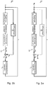
- the control arrangement shown comprises a control device 20 which is connected to a fluid energy machine 10 via a throttle 21.
- the fluid energy machine 10 generates a first torque M A.
- an auxiliary unit 30 is provided, which generates a third torque M H.
- the first torque M A and the third torque M H result in a second torque M W , which is applied to an output shaft 15, which is connected to the fluid energy machine 10.
- the speed n of the output shaft 15 is fed back via a feedback to the control device 20 and the auxiliary unit 30, whereby the control loops close.
- Fig. 1a shows the first and the second control loop in the first method step S 1 .
- the thickly marked lines and objects form the first control loop, which is active in method step S 1 .
- the second control loop is inactive in method step S 2 .
- the first control loop uses the first torque M A as the controlled variable, which is influenced by the position of the throttle 21.
- the first torque M A of the fluid energy machine 10 is regulated from an initial torque M 0 to an intermediate torque M Z. Since the second control loop is not active, the auxiliary unit 30 does not contribute to the control and the third torque M H is zero.
- the second torque M W acting on the output shaft 15 corresponds in the first method step S 1 the first torque M A. Due to the regulation via the throttle 21, the first control loop has a first time constant T 1 .
- Fig. 1b shows the first and the second control loop in the second method step S 2 .
- the thickly marked lines and objects form the second control loop, which is active in method step S 2 .
- the first control loop is no longer active in method step S 2 , but the position of the throttle 21 is kept largely constant.
- the first torque M A which is generated by the fluid energy machine 10, further corresponds to the intermediate torque M I.
- the second control loop uses the speed n of the output shaft 15 as the controlled variable, which is influenced by the auxiliary unit 30.
- the second torque M W corresponds to the intermediate torque M I and the speed n of the output shaft corresponds to the intermediate speed n I.
- the speed n of the output shaft 15 is now regulated from the intermediate speed n I to the target speed nz.
- the auxiliary unit 30 applies the third torque M H , which together with the first torque M A represents the second torque M W on the output shaft 15.
- the auxiliary unit 30 controls the speed n until it corresponds to the target speed nz and can be kept stable by the second control loop.
- the second control loop directly controls the rotational movement of the output shaft 15 without directly influencing the fluid energy machine 10. It is therefore only necessary to take into account the moment of inertia J of the fluid energy machine 10 and the loads connected to it, for example a generator 60.
- the second time constant T 2 of the second control loop is thus significantly less than the first time constant T 1 of the first control loop.
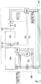
- Fig. 2 shows a detailed embodiment of the control arrangement which is used for a generator 40.
- the fluid energy machine is designed as an internal combustion engine 10.
- the generator 40 shown is used to feed energy into an electrical power supply network 50.
- the power generator 40 comprises a generator 60 which is designed as a synchronous generator.
- the internal combustion engine 10 can be operated in particular with a gaseous fuel, such as biogas.
- the internal combustion engine 10 is regulated via the position of its throttle 21.
- the internal combustion engine 10 has a generator clutch 11, via which the internal combustion engine 10 is connected to the generator 60.
- a speed sensor 12 is arranged, which measures the speed n of the output shaft 15 connected to the internal combustion engine 10.
- the power unit 40 comprises the auxiliary unit 30 configured as an electric auxiliary motor, which is connected via an electric clutch 31 to a flywheel 13 of the internal combustion engine 10 and controls the internal combustion engine 10 in a certain speed range for synchronizing the generator 60 with the electrical power supply network 50.
- the power unit 40 also includes the control device 20, which is designed as a frequency converter and is connected to the electrical auxiliary motor 30 and the electrical energy supply network 50 or another energy source.
- the power unit 40 further comprises a synchronization device 70, which is connected to the electrical power supply network 50, the control device 20 and the generator 60.
- the power unit 40 has a circuit breaker 80, which connects the generator 60 and the electrical power supply network 50 to one another.
- the circuit breaker 80 must therefore be switched off in order to interrupt the connection between the generator 60 and the electrical power supply network 50.
- the Synchronization device 70 monitors the synchronization status and controls the release of the connection between generator 60 and the electrical power supply network 50 via the circuit breaker 80. For this purpose, the synchronization device 70 supplies the circuit breaker 80 with a connection enable signal 72.
- the synchronization device 70 sends the circuit breaker 80 a connection enable signal 72, so that the circuit breaker 80 closes the connection between the generator 60 and the electrical power supply network 50.
- the generator 60 then feeds its energy into the electrical energy supply network 50.
- the internal combustion engine 10 is raised via the throttle 21 to a predetermined tolerance band defined by the target speed n Z of the generator 60.
- the target speed n Z corresponds, for example, to 1300 revolutions per minute.
- the electric auxiliary motor 30 controls the speed n of the internal combustion engine 10, which drives the generator 60.
- the electric auxiliary motor 30 itself is controlled by the control device 20.
- the control device 20 provides the auxiliary motor 30 with a suitable supply voltage UH with a frequency f H.
- the regulation of the control device 20 is based on data from the energy supply network 50 and up to two signals, optionally the speed signal 14 of the speed sensor 12 and absolutely the speed control signal 71 of the synchronization device 70.
- the speed signal 14 forms the current speed n, ie frequency, of the internal combustion engine 10 , also of the generator 60.
- the speed control signal 71 is generated by the synchronization device 70 based on the output 62 of the generator 60 and the data of the electrical power supply network 50 as a relative or absolute speed setpoint specification.
- the data of the electrical energy supply network 50 include the voltage U N , the phase position ⁇ N , the phase sequence and the frequency f N of the electrical energy supply network 50.
- the generator 60 is considered to be synchronized with the electrical power supply network 50 if the voltage U G , the phase position ⁇ G , the phase sequence and the frequency f G of the generator 60 are identical to the voltage U N , the phase position ⁇ N , the phase sequence and the frequency f N of the electrical power supply network 50.
- the voltage and phase sequence are negligible.
- the voltage U G of the generator 60 is regulated by an automatic voltage regulator 61 of the generator 60, which receives the voltage U N of the electrical power supply network 50 and the output voltage U G of the generator 60 as an input.
- the phase sequence is defined by the direction of rotation of the generator.
- the electric auxiliary motor 30 controls the frequency f G , speed n of the generator 60, and the phase position ⁇ G.
- the synchronization can be divided into several time periods A to D.
- the diagram according to Fig. 3 shows on the one hand the synchronization with regulation by the electric auxiliary motor 30 using the solid line and on the other hand the synchronization from the prior art with regulation purely by the throttle 21 using the dashed line.
- period A the internal combustion engine 10 is in starter mode.
- the speed n of the internal combustion engine corresponds to the initial speed n A of approximately 100 revolutions per minute.
- the internal combustion engine 10 is in in period B by regulating the throttle 21 to the intermediate speed n I of approximately 1300 revolutions per minute in accelerates the proximity of the target speed nz of 1500 revolutions per minute. This process takes about 4 seconds.
- the regulation by the electric auxiliary motor 30 begins. This is referred to as the so-called synchronization time ts.
- the speed n of the internal combustion engine 10 is regulated such that the speed n and thus the frequency of the generator 60 corresponds to the target speed nz. This is in Fig. 3 the case at time t 1 .
- the speed n is then regulated with small control pulses such that the phase position ⁇ G of the generator 60 is identical to the phase position ⁇ N of the electrical power supply network 50. Due to the small control time constant of a few hundred microseconds of the electrical frequency converter, the synchronization time t S is only limited by the moment of inertia J of the internal combustion engine 10.
- the synchronization time t S is approximately one second, but can also be significantly lower, for example in the range of 400 milliseconds.
- the voltage U G , the phase position ⁇ G , the phase sequence and the frequency fc of the generator 60 correspond to the voltage U N , the phase position ⁇ N , the phase sequence and the frequency f N of the electrical energy supply network 50.
- the generator 60 has thus been started and synchronized with the electrical power supply network 50 within a switch-on time t A of 8 seconds.
- the synchronization device 70 now sends the activation enable signal 72 to the circuit breaker 80.
- the circuit breaker 80 closes the connection between the generator 60 and the electrical power supply network 50 and the power generator 40 feeds energy into the energy supply network 50.
- the dashed line in time segments C and D shows that the comparatively much slower control with the throttle 21 of the internal combustion engine 10 approaches the target speed nz only comparatively slowly.
- the target speed n Z is only reached significantly later, at time t 1 * in time segment D.
- the regulation of the phase position is then completed at time t 2 *.
- the synchronization time t S * is in the range of 10 to 50 seconds, which leads to a significantly longer switch-on time t E * of 20 to 60 seconds.
- the internal combustion engine 10 is controlled exclusively by the first control loop. In periods C and D, the internal combustion engine 10 is controlled exclusively by the second control loop. However, it is also conceivable for both the first control loop and the second control loop to participate in the control of the internal combustion engine 10 at each of the time segments A to D.
Landscapes
- Engineering & Computer Science (AREA)
- Chemical & Material Sciences (AREA)
- Combustion & Propulsion (AREA)
- Mechanical Engineering (AREA)
- General Engineering & Computer Science (AREA)
- Power Engineering (AREA)
- Chemical Kinetics & Catalysis (AREA)
- General Chemical & Material Sciences (AREA)
- Oil, Petroleum & Natural Gas (AREA)
- Control Of Eletrric Generators (AREA)
Applications Claiming Priority (1)
| Application Number | Priority Date | Filing Date | Title |
|---|---|---|---|
| DE102018115781.9A DE102018115781B4 (de) | 2018-06-29 | 2018-06-29 | Verfahren zum Regeln einer Fluidenergiemaschine und eine Regelungsanordnung, insbesondere zum Durchführen des Verfahrens |
Publications (2)
| Publication Number | Publication Date |
|---|---|
| EP3587763A1 true EP3587763A1 (fr) | 2020-01-01 |
| EP3587763B1 EP3587763B1 (fr) | 2021-09-29 |
Family
ID=67137612
Family Applications (1)
| Application Number | Title | Priority Date | Filing Date |
|---|---|---|---|
| EP19183207.0A Not-in-force EP3587763B1 (fr) | 2018-06-29 | 2019-06-28 | Procédé de régulation d'une machine à énergie fluidique et dispositif de régulation, en particulier destiné à la mise en ouvre dudit procédé |
Country Status (2)
| Country | Link |
|---|---|
| EP (1) | EP3587763B1 (fr) |
| DE (1) | DE102018115781B4 (fr) |
Citations (8)
| Publication number | Priority date | Publication date | Assignee | Title |
|---|---|---|---|---|
| US4593364A (en) * | 1983-10-03 | 1986-06-03 | Westinghouse Electric Corp. | Floating deadband for speed feedback in turbine load control |
| US6784565B2 (en) * | 1997-09-08 | 2004-08-31 | Capstone Turbine Corporation | Turbogenerator with electrical brake |
| EP1504521A1 (fr) * | 2002-05-16 | 2005-02-09 | MTU Friedrichshafen GmbH | Procede de regulation d'une unite generateur/moteur a combustion interne |
| DE102006040929A1 (de) | 2006-08-31 | 2008-03-20 | Nordex Energy Gmbh | Verfahren zum Betrieb einer Windenergieanlage mit einem Synchrongenerator und einem Überlagerungsgetriebe |
| EP2315946A1 (fr) | 2008-08-13 | 2011-05-04 | Siemens Aktiengesellschaft | Machine à énergie hydraulique ou pneumatique |
| US8258640B2 (en) * | 2008-10-30 | 2012-09-04 | Caterpillar Inc. | Power system having transient control |
| US20160036230A1 (en) * | 2014-07-31 | 2016-02-04 | General Electric Company | Synchronous Condenser |
| WO2017137227A1 (fr) | 2016-02-12 | 2017-08-17 | Siemens Aktiengesellschaft | Ligne de turbine à gaz munie d'un moteur de démarrage |
Family Cites Families (2)
| Publication number | Priority date | Publication date | Assignee | Title |
|---|---|---|---|---|
| US8690725B2 (en) * | 2012-05-07 | 2014-04-08 | Ford Global Technologies, Llc | Engine restart torque spike management system for a hybrid vehicle |
| JP5925079B2 (ja) * | 2012-07-31 | 2016-05-25 | 日立オートモティブシステムズ株式会社 | モータ制御装置 |
-
2018
- 2018-06-29 DE DE102018115781.9A patent/DE102018115781B4/de not_active Expired - Fee Related
-
2019
- 2019-06-28 EP EP19183207.0A patent/EP3587763B1/fr not_active Not-in-force
Patent Citations (8)
| Publication number | Priority date | Publication date | Assignee | Title |
|---|---|---|---|---|
| US4593364A (en) * | 1983-10-03 | 1986-06-03 | Westinghouse Electric Corp. | Floating deadband for speed feedback in turbine load control |
| US6784565B2 (en) * | 1997-09-08 | 2004-08-31 | Capstone Turbine Corporation | Turbogenerator with electrical brake |
| EP1504521A1 (fr) * | 2002-05-16 | 2005-02-09 | MTU Friedrichshafen GmbH | Procede de regulation d'une unite generateur/moteur a combustion interne |
| DE102006040929A1 (de) | 2006-08-31 | 2008-03-20 | Nordex Energy Gmbh | Verfahren zum Betrieb einer Windenergieanlage mit einem Synchrongenerator und einem Überlagerungsgetriebe |
| EP2315946A1 (fr) | 2008-08-13 | 2011-05-04 | Siemens Aktiengesellschaft | Machine à énergie hydraulique ou pneumatique |
| US8258640B2 (en) * | 2008-10-30 | 2012-09-04 | Caterpillar Inc. | Power system having transient control |
| US20160036230A1 (en) * | 2014-07-31 | 2016-02-04 | General Electric Company | Synchronous Condenser |
| WO2017137227A1 (fr) | 2016-02-12 | 2017-08-17 | Siemens Aktiengesellschaft | Ligne de turbine à gaz munie d'un moteur de démarrage |
Also Published As
| Publication number | Publication date |
|---|---|
| EP3587763B1 (fr) | 2021-09-29 |
| DE102018115781B4 (de) | 2020-04-09 |
| DE102018115781A1 (de) | 2020-01-02 |
Similar Documents
| Publication | Publication Date | Title |
|---|---|---|
| DE3116340C2 (de) | Verfahren und Regeleinrichtung zum Begrenzen der bei Belastungsänderungen auftretenden thermischen Beanspruchung von Bauteilen einer Dampfturbine | |
| EP2118997B1 (fr) | Procédé de fonctionnement d'une centrale électrique | |
| DE60008799T2 (de) | Stromversorgungshilfsaggregat und dessen betriebsverfahren | |
| DE102007044522B4 (de) | Vorrichtung zur Regelung eines mit flüssigem und/oder gasförmigen Kraftstoff betreibbaren Verbrennungsmotors | |
| EP2644839B1 (fr) | Démarrage de turbines à gaz avec convertisseur de fréquence | |
| EP1820963B1 (fr) | Procédé de commande d'une éolienne | |
| EP0642707B1 (fr) | Procede et dispositif de regulation d'un ensemble turbine-generateur | |
| DE69218000T2 (de) | Gasturbinenregelsystem | |
| DE2358550A1 (de) | System zur getrennten oder gemeinsamen steuerung von kraftmaschinen | |
| DE10320580A1 (de) | Bremseinrichtung für eine Windenergieanlage mit einem die Windenergie in eine Drehbewegung umsetzenden Rotor und Verfahren zum Betrieb einer derartigen Bremseinrichtung | |
| EP3587763B1 (fr) | Procédé de régulation d'une machine à énergie fluidique et dispositif de régulation, en particulier destiné à la mise en ouvre dudit procédé | |
| DE112013006890T5 (de) | Energieerzeugungssystem | |
| CH699321A1 (de) | Kraftwerksanlage zum wahlweisen betrieb in stromnetzen mit unterschiedlicher netzfrequenz. | |
| DE102018115782B4 (de) | Stromaggregat und Verfahren zum Einspeisen von insbesondere aus gasförmigen Brennstoffen wie Biogas gewonnener Energie in ein elektrisches Energieversorgungsnetz | |
| DE102004005191A1 (de) | Verfahren und Vorrichtung zum Anfahren der Pumpturbine eines Pumpspeicherkraftwerkes | |
| EP1165951B1 (fr) | Procede de regulation d'une turbine a vapeur a soutirage de vapeur, dispositif de regulation y relatif et turbine a vapeur a soutirage de vapeur | |
| EP1903656B1 (fr) | Procédé de réglage primaire pour un secteur composite | |
| EP2620705A2 (fr) | Procédé d'adaptation de la puissance d'injection de courant produit à partir de biomasse | |
| DE10196104B4 (de) | Graphitkörper imprägniert mit einer Leichtmetall-Legierung, Verfahren zu dessen Herstellung und seine Verwendung | |
| EP2006514A2 (fr) | Moteur à combustion interne fixe | |
| EP3430244B1 (fr) | Synchronisation d'une turbine a l'aide d'un reseau a courant alternatif selon une trajectoire theorique pour l'angle differentiel theorique | |
| DE826672C (de) | Verfahren zur Regelung einer Gasturbinenanlage und Vorrichtung zu dessen Ausfuehrung | |
| WO2023006772A1 (fr) | Procédé permettant de faire fonctionner un groupe électrogène, dispositif permettant de faire fonctionner un groupe électrogène et groupe électrogène | |
| DE1145739B (de) | Regelung von Zwangdurchlaufdampferzeugern | |
| EP1709727A1 (fr) | Procede pour reduire la vitesse de rotation d'une transmission dans une eolienne et eolienne presentant au moins deux vitesses de rotation nominales |
Legal Events
| Date | Code | Title | Description |
|---|---|---|---|
| PUAI | Public reference made under article 153(3) epc to a published international application that has entered the european phase |
Free format text: ORIGINAL CODE: 0009012 |
|
| STAA | Information on the status of an ep patent application or granted ep patent |
Free format text: STATUS: THE APPLICATION HAS BEEN PUBLISHED |
|
| AK | Designated contracting states |
Kind code of ref document: A1 Designated state(s): AL AT BE BG CH CY CZ DE DK EE ES FI FR GB GR HR HU IE IS IT LI LT LU LV MC MK MT NL NO PL PT RO RS SE SI SK SM TR |
|
| AX | Request for extension of the european patent |
Extension state: BA ME |
|
| STAA | Information on the status of an ep patent application or granted ep patent |
Free format text: STATUS: REQUEST FOR EXAMINATION WAS MADE |
|
| 17P | Request for examination filed |
Effective date: 20200629 |
|
| RBV | Designated contracting states (corrected) |
Designated state(s): AL AT BE BG CH CY CZ DE DK EE ES FI FR GB GR HR HU IE IS IT LI LT LU LV MC MK MT NL NO PL PT RO RS SE SI SK SM TR |
|
| STAA | Information on the status of an ep patent application or granted ep patent |
Free format text: STATUS: EXAMINATION IS IN PROGRESS |
|
| 17Q | First examination report despatched |
Effective date: 20200914 |
|
| GRAP | Despatch of communication of intention to grant a patent |
Free format text: ORIGINAL CODE: EPIDOSNIGR1 |
|
| STAA | Information on the status of an ep patent application or granted ep patent |
Free format text: STATUS: GRANT OF PATENT IS INTENDED |
|
| RIC1 | Information provided on ipc code assigned before grant |
Ipc: F02B 63/04 20060101AFI20210615BHEP Ipc: F02D 29/06 20060101ALI20210615BHEP Ipc: H02J 3/00 20060101ALI20210615BHEP Ipc: H02P 9/04 20060101ALI20210615BHEP Ipc: F02B 43/00 20060101ALN20210615BHEP Ipc: F02M 21/00 20060101ALN20210615BHEP |
|
| RIC1 | Information provided on ipc code assigned before grant |
Ipc: F02B 63/04 20060101AFI20210705BHEP Ipc: F02D 29/06 20060101ALI20210705BHEP Ipc: H02J 3/00 20060101ALI20210705BHEP Ipc: H02P 9/04 20060101ALI20210705BHEP Ipc: F02B 43/00 20060101ALN20210705BHEP Ipc: F02M 21/00 20060101ALN20210705BHEP |
|
| INTG | Intention to grant announced |
Effective date: 20210719 |
|
| GRAS | Grant fee paid |
Free format text: ORIGINAL CODE: EPIDOSNIGR3 |
|
| GRAA | (expected) grant |
Free format text: ORIGINAL CODE: 0009210 |
|
| STAA | Information on the status of an ep patent application or granted ep patent |
Free format text: STATUS: THE PATENT HAS BEEN GRANTED |
|
| AK | Designated contracting states |
Kind code of ref document: B1 Designated state(s): AL AT BE BG CH CY CZ DE DK EE ES FI FR GB GR HR HU IE IS IT LI LT LU LV MC MK MT NL NO PL PT RO RS SE SI SK SM TR |
|
| REG | Reference to a national code |
Ref country code: GB Ref legal event code: FG4D Free format text: NOT ENGLISH |
|
| REG | Reference to a national code |
Ref country code: DE Ref legal event code: R096 Ref document number: 502019002374 Country of ref document: DE |
|
| REG | Reference to a national code |
Ref country code: CH Ref legal event code: EP Ref country code: AT Ref legal event code: REF Ref document number: 1434383 Country of ref document: AT Kind code of ref document: T Effective date: 20211015 |
|
| REG | Reference to a national code |
Ref country code: IE Ref legal event code: FG4D Free format text: LANGUAGE OF EP DOCUMENT: GERMAN |
|
| REG | Reference to a national code |
Ref country code: LT Ref legal event code: MG9D |
|
| PG25 | Lapsed in a contracting state [announced via postgrant information from national office to epo] |
Ref country code: HR Free format text: LAPSE BECAUSE OF FAILURE TO SUBMIT A TRANSLATION OF THE DESCRIPTION OR TO PAY THE FEE WITHIN THE PRESCRIBED TIME-LIMIT Effective date: 20210929 Ref country code: NO Free format text: LAPSE BECAUSE OF FAILURE TO SUBMIT A TRANSLATION OF THE DESCRIPTION OR TO PAY THE FEE WITHIN THE PRESCRIBED TIME-LIMIT Effective date: 20211229 Ref country code: LT Free format text: LAPSE BECAUSE OF FAILURE TO SUBMIT A TRANSLATION OF THE DESCRIPTION OR TO PAY THE FEE WITHIN THE PRESCRIBED TIME-LIMIT Effective date: 20210929 Ref country code: BG Free format text: LAPSE BECAUSE OF FAILURE TO SUBMIT A TRANSLATION OF THE DESCRIPTION OR TO PAY THE FEE WITHIN THE PRESCRIBED TIME-LIMIT Effective date: 20211229 Ref country code: FI Free format text: LAPSE BECAUSE OF FAILURE TO SUBMIT A TRANSLATION OF THE DESCRIPTION OR TO PAY THE FEE WITHIN THE PRESCRIBED TIME-LIMIT Effective date: 20210929 Ref country code: RS Free format text: LAPSE BECAUSE OF FAILURE TO SUBMIT A TRANSLATION OF THE DESCRIPTION OR TO PAY THE FEE WITHIN THE PRESCRIBED TIME-LIMIT Effective date: 20210929 Ref country code: SE Free format text: LAPSE BECAUSE OF FAILURE TO SUBMIT A TRANSLATION OF THE DESCRIPTION OR TO PAY THE FEE WITHIN THE PRESCRIBED TIME-LIMIT Effective date: 20210929 |
|
| REG | Reference to a national code |
Ref country code: NL Ref legal event code: MP Effective date: 20210929 |
|
| PG25 | Lapsed in a contracting state [announced via postgrant information from national office to epo] |
Ref country code: LV Free format text: LAPSE BECAUSE OF FAILURE TO SUBMIT A TRANSLATION OF THE DESCRIPTION OR TO PAY THE FEE WITHIN THE PRESCRIBED TIME-LIMIT Effective date: 20210929 Ref country code: GR Free format text: LAPSE BECAUSE OF FAILURE TO SUBMIT A TRANSLATION OF THE DESCRIPTION OR TO PAY THE FEE WITHIN THE PRESCRIBED TIME-LIMIT Effective date: 20211230 |
|
| PG25 | Lapsed in a contracting state [announced via postgrant information from national office to epo] |
Ref country code: IS Free format text: LAPSE BECAUSE OF FAILURE TO SUBMIT A TRANSLATION OF THE DESCRIPTION OR TO PAY THE FEE WITHIN THE PRESCRIBED TIME-LIMIT Effective date: 20220129 Ref country code: SK Free format text: LAPSE BECAUSE OF FAILURE TO SUBMIT A TRANSLATION OF THE DESCRIPTION OR TO PAY THE FEE WITHIN THE PRESCRIBED TIME-LIMIT Effective date: 20210929 Ref country code: RO Free format text: LAPSE BECAUSE OF FAILURE TO SUBMIT A TRANSLATION OF THE DESCRIPTION OR TO PAY THE FEE WITHIN THE PRESCRIBED TIME-LIMIT Effective date: 20210929 Ref country code: PT Free format text: LAPSE BECAUSE OF FAILURE TO SUBMIT A TRANSLATION OF THE DESCRIPTION OR TO PAY THE FEE WITHIN THE PRESCRIBED TIME-LIMIT Effective date: 20220131 Ref country code: PL Free format text: LAPSE BECAUSE OF FAILURE TO SUBMIT A TRANSLATION OF THE DESCRIPTION OR TO PAY THE FEE WITHIN THE PRESCRIBED TIME-LIMIT Effective date: 20210929 Ref country code: NL Free format text: LAPSE BECAUSE OF FAILURE TO SUBMIT A TRANSLATION OF THE DESCRIPTION OR TO PAY THE FEE WITHIN THE PRESCRIBED TIME-LIMIT Effective date: 20210929 Ref country code: ES Free format text: LAPSE BECAUSE OF FAILURE TO SUBMIT A TRANSLATION OF THE DESCRIPTION OR TO PAY THE FEE WITHIN THE PRESCRIBED TIME-LIMIT Effective date: 20210929 Ref country code: EE Free format text: LAPSE BECAUSE OF FAILURE TO SUBMIT A TRANSLATION OF THE DESCRIPTION OR TO PAY THE FEE WITHIN THE PRESCRIBED TIME-LIMIT Effective date: 20210929 Ref country code: CZ Free format text: LAPSE BECAUSE OF FAILURE TO SUBMIT A TRANSLATION OF THE DESCRIPTION OR TO PAY THE FEE WITHIN THE PRESCRIBED TIME-LIMIT Effective date: 20210929 Ref country code: AL Free format text: LAPSE BECAUSE OF FAILURE TO SUBMIT A TRANSLATION OF THE DESCRIPTION OR TO PAY THE FEE WITHIN THE PRESCRIBED TIME-LIMIT Effective date: 20210929 |
|
| REG | Reference to a national code |
Ref country code: DE Ref legal event code: R097 Ref document number: 502019002374 Country of ref document: DE |
|
| PG25 | Lapsed in a contracting state [announced via postgrant information from national office to epo] |
Ref country code: DK Free format text: LAPSE BECAUSE OF FAILURE TO SUBMIT A TRANSLATION OF THE DESCRIPTION OR TO PAY THE FEE WITHIN THE PRESCRIBED TIME-LIMIT Effective date: 20210929 |
|
| PLBE | No opposition filed within time limit |
Free format text: ORIGINAL CODE: 0009261 |
|
| STAA | Information on the status of an ep patent application or granted ep patent |
Free format text: STATUS: NO OPPOSITION FILED WITHIN TIME LIMIT |
|
| 26N | No opposition filed |
Effective date: 20220630 |
|
| PG25 | Lapsed in a contracting state [announced via postgrant information from national office to epo] |
Ref country code: SI Free format text: LAPSE BECAUSE OF FAILURE TO SUBMIT A TRANSLATION OF THE DESCRIPTION OR TO PAY THE FEE WITHIN THE PRESCRIBED TIME-LIMIT Effective date: 20210929 |
|
| PG25 | Lapsed in a contracting state [announced via postgrant information from national office to epo] |
Ref country code: MC Free format text: LAPSE BECAUSE OF FAILURE TO SUBMIT A TRANSLATION OF THE DESCRIPTION OR TO PAY THE FEE WITHIN THE PRESCRIBED TIME-LIMIT Effective date: 20210929 |
|
| REG | Reference to a national code |
Ref country code: CH Ref legal event code: PL |
|
| REG | Reference to a national code |
Ref country code: BE Ref legal event code: MM Effective date: 20220630 |
|
| PG25 | Lapsed in a contracting state [announced via postgrant information from national office to epo] |
Ref country code: LU Free format text: LAPSE BECAUSE OF NON-PAYMENT OF DUE FEES Effective date: 20220628 Ref country code: LI Free format text: LAPSE BECAUSE OF NON-PAYMENT OF DUE FEES Effective date: 20220630 Ref country code: IE Free format text: LAPSE BECAUSE OF NON-PAYMENT OF DUE FEES Effective date: 20220628 Ref country code: FR Free format text: LAPSE BECAUSE OF NON-PAYMENT OF DUE FEES Effective date: 20220630 Ref country code: CH Free format text: LAPSE BECAUSE OF NON-PAYMENT OF DUE FEES Effective date: 20220630 |
|
| PG25 | Lapsed in a contracting state [announced via postgrant information from national office to epo] |
Ref country code: BE Free format text: LAPSE BECAUSE OF NON-PAYMENT OF DUE FEES Effective date: 20220630 |
|
| PGFP | Annual fee paid to national office [announced via postgrant information from national office to epo] |
Ref country code: DE Payment date: 20230703 Year of fee payment: 5 |
|
| GBPC | Gb: european patent ceased through non-payment of renewal fee |
Effective date: 20230628 |
|
| PG25 | Lapsed in a contracting state [announced via postgrant information from national office to epo] |
Ref country code: SM Free format text: LAPSE BECAUSE OF FAILURE TO SUBMIT A TRANSLATION OF THE DESCRIPTION OR TO PAY THE FEE WITHIN THE PRESCRIBED TIME-LIMIT Effective date: 20210929 Ref country code: MK Free format text: LAPSE BECAUSE OF FAILURE TO SUBMIT A TRANSLATION OF THE DESCRIPTION OR TO PAY THE FEE WITHIN THE PRESCRIBED TIME-LIMIT Effective date: 20210929 Ref country code: CY Free format text: LAPSE BECAUSE OF FAILURE TO SUBMIT A TRANSLATION OF THE DESCRIPTION OR TO PAY THE FEE WITHIN THE PRESCRIBED TIME-LIMIT Effective date: 20210929 Ref country code: GB Free format text: LAPSE BECAUSE OF NON-PAYMENT OF DUE FEES Effective date: 20230628 |
|
| PG25 | Lapsed in a contracting state [announced via postgrant information from national office to epo] |
Ref country code: HU Free format text: LAPSE BECAUSE OF FAILURE TO SUBMIT A TRANSLATION OF THE DESCRIPTION OR TO PAY THE FEE WITHIN THE PRESCRIBED TIME-LIMIT; INVALID AB INITIO Effective date: 20190628 |
|
| PGFP | Annual fee paid to national office [announced via postgrant information from national office to epo] |
Ref country code: IT Payment date: 20240430 Year of fee payment: 6 |
|
| PG25 | Lapsed in a contracting state [announced via postgrant information from national office to epo] |
Ref country code: TR Free format text: LAPSE BECAUSE OF FAILURE TO SUBMIT A TRANSLATION OF THE DESCRIPTION OR TO PAY THE FEE WITHIN THE PRESCRIBED TIME-LIMIT Effective date: 20210929 |
|
| PG25 | Lapsed in a contracting state [announced via postgrant information from national office to epo] |
Ref country code: IT Free format text: LAPSE BECAUSE OF NON-PAYMENT OF DUE FEES Effective date: 20230628 |
|
| PG25 | Lapsed in a contracting state [announced via postgrant information from national office to epo] |
Ref country code: MT Free format text: LAPSE BECAUSE OF FAILURE TO SUBMIT A TRANSLATION OF THE DESCRIPTION OR TO PAY THE FEE WITHIN THE PRESCRIBED TIME-LIMIT Effective date: 20210929 |
|
| REG | Reference to a national code |
Ref country code: DE Ref legal event code: R119 Ref document number: 502019002374 Country of ref document: DE |
|
| PG25 | Lapsed in a contracting state [announced via postgrant information from national office to epo] |
Ref country code: DE Free format text: LAPSE BECAUSE OF NON-PAYMENT OF DUE FEES Effective date: 20250101 |
|
| REG | Reference to a national code |
Ref country code: AT Ref legal event code: MM01 Ref document number: 1434383 Country of ref document: AT Kind code of ref document: T Effective date: 20240628 |
|
| PG25 | Lapsed in a contracting state [announced via postgrant information from national office to epo] |
Ref country code: AT Free format text: LAPSE BECAUSE OF NON-PAYMENT OF DUE FEES Effective date: 20240628 |
|
| PGFP | Annual fee paid to national office [announced via postgrant information from national office to epo] |
Ref country code: AT Payment date: 20260410 Year of fee payment: 5 |