EP3587930A1 - Cooking appliance comprising a ventilation system - Google Patents
Cooking appliance comprising a ventilation system Download PDFInfo
- Publication number
- EP3587930A1 EP3587930A1 EP19179738.0A EP19179738A EP3587930A1 EP 3587930 A1 EP3587930 A1 EP 3587930A1 EP 19179738 A EP19179738 A EP 19179738A EP 3587930 A1 EP3587930 A1 EP 3587930A1
- Authority
- EP
- European Patent Office
- Prior art keywords
- air
- cavity
- ventilation channel
- vent aperture
- blower
- Prior art date
- Legal status (The legal status is an assumption and is not a legal conclusion. Google has not performed a legal analysis and makes no representation as to the accuracy of the status listed.)
- Granted
Links
Images


Classifications
-
- F—MECHANICAL ENGINEERING; LIGHTING; HEATING; WEAPONS; BLASTING
- F24—HEATING; RANGES; VENTILATING
- F24C—DOMESTIC STOVES OR RANGES ; DETAILS OF DOMESTIC STOVES OR RANGES, OF GENERAL APPLICATION
- F24C15/00—Details
- F24C15/006—Arrangements for circulation of cooling air
-
- F—MECHANICAL ENGINEERING; LIGHTING; HEATING; WEAPONS; BLASTING
- F24—HEATING; RANGES; VENTILATING
- F24C—DOMESTIC STOVES OR RANGES ; DETAILS OF DOMESTIC STOVES OR RANGES, OF GENERAL APPLICATION
- F24C15/00—Details
- F24C15/20—Removing cooking fumes
- F24C15/2007—Removing cooking fumes from oven cavities
-
- F—MECHANICAL ENGINEERING; LIGHTING; HEATING; WEAPONS; BLASTING
- F24—HEATING; RANGES; VENTILATING
- F24C—DOMESTIC STOVES OR RANGES ; DETAILS OF DOMESTIC STOVES OR RANGES, OF GENERAL APPLICATION
- F24C15/00—Details
- F24C15/20—Removing cooking fumes
- F24C15/2021—Arrangement or mounting of control or safety systems
-
- F—MECHANICAL ENGINEERING; LIGHTING; HEATING; WEAPONS; BLASTING
- F24—HEATING; RANGES; VENTILATING
- F24C—DOMESTIC STOVES OR RANGES ; DETAILS OF DOMESTIC STOVES OR RANGES, OF GENERAL APPLICATION
- F24C15/00—Details
- F24C15/32—Arrangements of ducts for hot gases, e.g. in or around baking ovens
- F24C15/322—Arrangements of ducts for hot gases, e.g. in or around baking ovens with forced circulation
Definitions
- the device is in the field of cooking appliances, and more specifically, a ventilation system for a cooking appliance that utilizes low pressure areas to generate suction for drawing air from one portion of the cooking appliance to another.
- a cooking appliance in at least one aspect, includes a housing having a heating cavity defined therein, wherein a heat source is in thermal communication with the heating cavity.
- a cooling channel is disposed proximate a sidewall of the housing.
- a blower selectively operates to move at least cooling air through the cooling channel and to an air outlet.
- a vent aperture extends through the sidewall between the heating cavity and a ventilation channel.
- the ventilation channel includes a narrowed portion proximate the vent aperture, wherein during operation of the blower, the narrowed portion defines a low static pressure region of the ventilation channel that draws cavity air from the heating cavity and directs the cavity air into the ventilation channel to be combined with the cooling air.
- a ventilation system for a cooking appliance includes a housing having a sidewall and a heating cavity defined within the housing.
- An outer cooling path extends around at least a portion of the housing.
- a ventilation channel is disposed proximate a sidewall of the housing and at least partially within the outer cooling path.
- a blower selectively operates to move cavity air through the exhaust channel and to an air outlet.
- a low pressure space is defined within the cooling path proximate the blower.
- the ventilation channel extends from the vent aperture and into the low pressure space. The blower contemporaneously draws cooling air through the outer cooling path and cavity air through the ventilation channel.
- the low pressure space and the ventilation channel maintain the cavity air contained within the ventilation channel to be combined with the cooling air at a downstream location.
- a cooking appliance in at least another aspect, includes an upper housing that defines an upper heating cavity.
- a lower housing defines a lower heating cavity.
- An outer cooling path extends around at least a portion of the upper and lower housings to an air outlet.
- Upper and lower blowers operate to selectively move cooling air through the outer cooling path.
- a ventilation channel is at least partially disposed within the outer cooling path. The ventilation channel extends from a vent aperture defined within the upper heating cavity to a downstream location of the outer cooling path. Operation of at least the lower blower contemporaneously moves the cooling air through the outer cooling path and moves cavity air from the upper heating cavity and to the downstream location via the ventilation channel. The cooling air and the cavity air combine at the downstream location.
- the terms "upper,” “lower,” “right,” “left,” “rear,” “front,” “vertical,” “horizontal,” and derivatives thereof shall relate to the device as oriented in FIG. 1 .
- the device may assume various alternative orientations and step sequences, except where expressly specified to the contrary.
- the specific devices and processes illustrated in the attached drawings, and described in the following specification are simply exemplary embodiments of the inventive concepts defined in the appended claims. Hence, specific dimensions and other physical characteristics relating to the embodiments disclosed herein are not to be considered as limiting, unless the claims expressly state otherwise.
- reference numeral 10 generally refers to a cooling channel for a ventilation system 12 of a cooking appliance 14, where the cooling channel 10 serves to move cooling air 16 around portions of the cooking appliance 14.
- the cooling channel 10 also allows for movement of cavity air 18 from one or more heating cavities 20 and into the cooling channel 10. This cavity air 18 can then be circulated through the ventilation system 12 and removed from the appliance 14 through an air outlet 22 of the ventilation system 12.
- the cooking appliance 14 can include a housing 24 having at least one heating cavity 20 defined therein.
- a heat source 26 is disposed within the housing 24 and is placed in thermal communication with the heating cavity 20.
- the cooling channel 10 is disposed proximate at least one sidewall 28, typically a back wall 30, of the housing 24 and is typically positioned at or near an exterior surface 32 of the housing 24.
- a blower 34 for the ventilation system 12 of the cooking appliance 14 is disposed proximate the housing 24. The blower 34 selectively operates to move cooling air 16 through the cooling channel 10 and to the air outlet 22.
- the cooling channel 10 is typically defined between the housing 24 and a channel cover 44 attached to the housing 24.
- a vent aperture 36 is positioned within the housing 24 and extends through the sidewall 28 between the heating cavity 20 and a ventilation channel 42.
- the ventilation channel 42 in certain aspects of the device, can include a narrowed portion 38 that is positioned near or proximate the vent aperture 36.
- the narrowed portion 38 defines a low static-pressure region 40 of the ventilation channel 42.
- This low static-pressure region 40 serves to draw or suction cavity air 18 from within the heating cavity 20.
- This suction 82 generated by the low static-pressure region 40 directs the cavity air 18 into the ventilation channel 42 via the vent aperture 36.
- the cavity air 18 is combined with the cooling air 16 within the cooling channel 10.
- the cavity air 18 and the cooling air 16 are combined within a downstream portion 50 of the cooling channel 10.
- the ventilation channel 42 is at least partially disposed within the cooling channel 10.
- the ventilation channel 42 extends from the vent aperture 36 to the downstream location or downstream portion 50.
- This downstream portion 50 is typically distal from the vent aperture 36, such as an area beneath the housing 24 and near the air outlet 22.
- the ventilation channel 42 is a substantially closed duct that separates the cavity air 18 from the cooling air 16 within the cooling channel 10.
- the cooling channel 10 serves to cool various components of the appliance 14 that are disposed within the back wall 30 and at least partially disposed within the cooling channel 10. These components can include various heat sources 26 and other portions of the appliance 14.
- the cavity air 18 can include grease, debris, particulate matter and other cooking byproducts. These cooking byproducts are ventilated from the heating cavity 20 and the appliance 14. These cooking byproducts also are separated from the heat sources 26 (such as convection fan 290) and other components of the appliance 14 contained within the cooling channel 10. The cooking byproducts can clog or otherwise degrade the performance of these components. Accordingly, the use of the ventilation channel 42 allows for movement of the cavity air 18 through the cooling channel 10, but also maintains the cavity air 18 separate from the cooling air 16 and the components of the appliance 14.
- the narrowed portion 38 of the ventilation channel 42 can be defined by a deflecting body 60 that is disposed within the ventilation channel 42.
- the deflecting body 60 is positioned within the ventilation channel 42 and occupies at least a portion of the ventilation channel 42 near the vent aperture 36.
- the cavity air 18 moving through the ventilation channel 42 and past the deflecting bodies 60 is caused to move faster around the deflecting bodies 60, thereby creating the low static-pressure region 40 in the ventilation channel 42 at the vent aperture 36.
- This acceleration of the cooling air 16 causes a Venturi-effect section 120 within the ventilation channel 42 that forms the low static-pressure region 40 at the vent aperture 36.
- the deflecting bodies 60 that form the narrowed portion 38 of the ventilation channel 42 can be made to have different cross sections that are formed by attaching the deflecting bodies 60 inside the ventilation channel 42.
- Shapes of the deflecting bodies 60 can include, but are not limited to, triangles, wedges, arcuate shapes, undulating shapes, irregular shapes, combinations thereof, and other similar shapes that can define the narrowed portion 38 of the ventilation channel 42.
- the narrowed portion 38 of the ventilation channel 42 serves to create a Venturi-effect section 120 within the low static-pressure region 40 that accelerates the cooling air 16 at the vent aperture 36 of the ventilation channel 42.
- the low static-pressure region 40 of the ventilation channel 42 creates the Venturi effect that serves to draw cavity air 18 out from the heating cavity 20 and through the vent aperture 36 and into the ventilation channel 42 near the deflecting bodies 60.
- the deflecting body 60 can include a leading portion 62 that includes a steep transition 64.
- This leading portion 62 serves to quickly accelerate the cavity air 18 to define the low static-pressure region 40.
- a trailing portion 66 can be positioned downstream of the leading portion 62 and can include a gradual transition 68.
- This gradual transition 68 serves to gradually increase the static pressure so that at least some suction 82 is generated along the length of the trailing portion 66 of the deflecting body 60.
- This gradual transition 68 of the trailing portion 66 also serves to better combine the various streams of cavity air 18, and also serves to better combine the cavity air 18 with the cooling air 16 at the downstream portion 50 in a generally laminar transition 70.
- the deflecting body 60 can also include a suction gap 72 that is defined between the leading and trailing portions 62, 66.
- the suction gap 72 allows for better movement of the cavity air 18 through the vent aperture 36 and into the ventilation channel 42. In this manner, the suction gap 72 can at least partially define the vent aperture 36.
- the trailing portion 66 can define a step 74 that is a narrowed top edge 76 of the trailing portion 66. The narrowed top edge 76 steps inward from the leading portion 62 so that the step 74 defines at least a portion of the Venturi-effect section 120 of the vent aperture 36.
- the narrowed portion 38 of the ventilation channel 42 can also be formed through manipulating the shape of boundary walls 80 of the cooling channel 10 in the area of the vent apertures 36.
- the boundary walls 80 of the cooling channel 10 can be bent or deformed inward or flattened to a thinner profile to form the narrowed portion 38 of the cooling channel 10.
- Making the cooling channel 10 narrower can result in the low static-pressure region 40 that generates the Venturi-effect section 120 to suction cavity air 18 through the vent aperture 36 and into the ventilation channel 42.
- the deflecting body 60 typically surrounds at least a portion of the vent aperture 36.
- the Venturi effect generated by the deflecting body 60 can cause suction 82 through the vent aperture 36 for drawing cavity air 18 from the heating cavity 20 and into the ventilation channel 42.
- the amount of suction 82 created in the low static-pressure region 40 can be regulated by the operating speed of the blower 34, or by a pulse-type operation of the blower 34.
- the cooking appliance 14 can also include a second or lower heating cavity 90 that is positioned within the housing 24 and typically below the primary or upper heating cavity 92.
- a secondary or lower vent aperture 94 can serve the lower heating cavity 90 and can extend through the lower housing 96 between the lower heating cavity 90 and the ventilation channel 42.
- the ventilation channel 42 can include a secondary and, typically, a lower narrowed portion 98 disposed near or proximate the lower vent aperture 94.
- the lower narrowed portion 98 defines another of the low static-pressure regions 40 of the ventilation channel 42.
- This second low static-pressure region 40 forms another Venturi-effect section 120 of the ventilation channel 42 that draws secondary cavity air or lower cavity air 100 from the lower heating cavity 90.
- This lower cavity air 100 is directed from the lower heating cavity 90 and into the ventilation channel 42 via the lower vent aperture 94.
- This lower cavity air 100 is then combined within the ventilation channel 42 with the cavity air 18 from the upper heating cavity 92.
- the lower cavity air 100 and the cavity air 18 can then be combined with the cooling air 16 at the downstream portion 50 of the cooling channel 10.
- the ventilation channel 42 extends continuously between the upper vent aperture 102 and the lower vent aperture 94 and corresponding upper and lower narrowed portions 106, 98.
- the cooking appliance 14 typically includes a single ventilation channel 42 that serves each of the upper heating cavity 92 and lower heating cavity 90, which can also be referred to as the upper and lower heating cavities 92, 90 of a dual-cavity oven.
- This principle can also be expanded to additional heating cavities 20 where a particular cooking appliance 14 can include three or more heating cavities 20. In an exemplary embodiment, four heating cavities 20 are shown in FIG. 2 .
- the ventilation channel 42 extends past each vent aperture 36 of the various heating cavities 20.
- the cooking byproducts from the various heating cavities 20 are separated from the remainder of the cooling channel 10, and, in turn, the cooling air 16 and the various components of the appliance 14 that are cooled by the cooling air 16. While the heating cavities 20 are described herein as vertically oriented, horizontal orientations of heating cavities 20 and other directional orientations are contemplated.
- the ventilation channel 42 can extend past each vent aperture 36 and corresponding narrowed portions 38 of the various heating cavities 20.
- a single blower 34 can be utilized within the cooking appliance 14 to move cavity air 18 through the ventilation channel 42.
- a single blower 34 can be used to move cavity air 18 through several vent apertures 36 and corresponding narrowed portions 38. While an appliance 14 having multiple heating cavities 20 will typically have multiple blowers 34, one of these blowers 34 may be utilized for removing cavity air 18 from the heating cavities 20 and into the ventilation channel 42 that serves several corresponding heating cavities 20.
- blowers 34 can be used to move cavity air 18 from multiple heating cavities 20 through the single ventilation channel 42. Where multiple blowers 34 are used, each blower 34 is typically positioned at separate positions of the ventilation channel 42 or can be connected to separate and dedicated ventilation channels 42. These separate and dedicated ventilation channels 42 are disposed within the cooling channel 10 and terminate at the downstream portion 50 of the cooling channel 10. Typically a single blower 34 will serve a common ventilation channel 42 that can provide for efficient movement of the various streams of cavity air 18 that are drawn or suctioned from the various heating cavities 20 of the appliance 14 and moved to the downstream portion 50 to be combined with the cooling air 16 in the cooling channel 10.
- the various heating cavities 20 typically include a vent aperture 36 that leads into the ventilation channel 42.
- the vent aperture 36 can be positioned within a top wall 52 of the heating cavity 20.
- the ventilation channel 42 then extends from the vent aperture 36 within the top wall 52 and extends through the ventilation channel 42 and into the low pressure space 182 of the corresponding blower 34.
- This configuration can be referred to as a top-reverse configuration 112 where the cavity air 18 is moved through the top wall 52 of the heating cavity 20 and toward the remainder of the ventilation channel 42 that is positioned near the back wall 30 of the appliance 14.
- the vent aperture 36 can be located within a back wall 30 of the heating cavity 20.
- cavity air 18 is moved through the vent aperture 36 in the back wall 30 and is moved through the ventilation channel 42 toward a low pressure space 182 of a blower 34 positioned below the heating cavity 20.
- This configuration can be referred to as a back-reverse configuration 114.
- the blower 34 that serves the respective heating cavity 20 forms the low pressure space 182 that moves the cavity air 18 from the respective heating cavity 20.
- This configuration is typically seen in appliances 14 that have a single heating cavity 20 as well as other configurations.
- the back-reverse configuration 114 is typically found in appliances 14 having at least an upper heating cavity 92 and a lower heating cavity 90.
- the lower blower 216 serves to draw cavity air 18 from the upper heating cavity 92.
- the vent aperture 36 within the upper heating cavity 92 is positioned within a back wall 30 of the upper heating cavity 92.
- the ventilation channel 42 extends from the vent aperture 36 within the back wall 30 of the upper heating cavity 92 and extends downward to the low pressure space 182 of the lower blower 216.
- the lower blower 216 then moves the cavity air 18 from the upper heating cavity 92 through the remainder of the ventilation channel 42 and toward the air outlet 22 for the appliance 14.
- the various heating cavities 20 can include different ventilation configurations. These ventilation configurations can include the top-reverse configuration 112 or the back-reverse configuration 114 described above. In an appliance 14 having multiple heating cavities 20, one of the heating cavities 20 may include a conventional forward ventilation configuration that is known in the art. The remaining heating cavities 20 will typically include the back-reverse configuration 114, the top-reverse configuration 112, or a variation of these novel configurations, as disclosed herein. In various aspects of the device, it is also contemplated that one of the heating cavities 20 may include no vent apertures 36.
- various aspects of the cooking appliance 14 can include upper and lower heating cavities 92, 90 that are served by respective upper and lower vent apertures 102, 94.
- the narrowed portions 38 of the ventilation channel 42 can create a Venturi-effect section 120 of the ventilation channel 42 at each of the upper and lower vent apertures 102, 94.
- upper cavity air 108 is drawn from the upper heating cavity 92 and through the upper vent aperture 102. This upper cavity air 108 is then moved through the narrowed portion 38 of the ventilation channel 42 at the lower vent aperture 94.
- the lower vent aperture 94 can include a deflecting body 60 in the form of a cover member 130 that extends around at least a portion of the lower vent aperture 94.
- This cover member 130 can include an aerodynamic deflector 132 that diverts upper cavity air 108 from the upper heating cavity 92 to defect around the lower vent aperture 94 at the lower heating cavity 90.
- the aerodynamic deflector 132 also generates the low static-pressure region 40 at the lower vent aperture 94.
- this aerodynamic deflector 132 extends downstream of the lower vent aperture 94 and serves to prevent infiltration of upper cavity air 108 into the lower vent aperture 94. In this manner, various particles, fumes, debris, and other cooking byproducts that may be contained within the upper cavity air 108 are prevented from entering into the lower heating cavity 90 via the lower vent aperture 94. Infiltration of the upper cavity air 108 infiltrating into the lower vent aperture 94 may occur in instances when a door of the upper heating cavity 92 is rapidly closed or slammed. This rapid closure of the door can increase the air pressure within the ventilation channel 42. This increased air pressure may tend the upper cavity air 108 toward the lower vent aperture 94. Using the aerodynamic deflector 132 that extends around the lower vent aperture 94, contamination between the upper and lower heating cavities 92, 90 can be substantially eliminated or kept to a minimum through the use of the aerodynamic deflector 132.
- the aerodynamic deflector 132 surrounds the lower vent aperture 94 and includes a tapered transition 140 that defines the low static-pressure region 40 and generates Venturi-effect suction 82 that serves to introduce lower cavity air 100 from the lower heating cavity 90.
- the lower cavity air 100 then combines with the upper cavity air 108 and subsequently combines with the remainder of cooling air 16 at a position downstream of the lower vent aperture 94.
- This tapered transition 140 of the aerodynamic deflector 132 forms an accelerated air region 142 that utilizes the Venturi effect to promote the suction 82 or outflow of lower cavity air 100 from the lower heating cavity 90 through the lower vent aperture 94 and into the ventilation channel 42.
- This tapered transition 140 also prevents the inflow of upper cavity air 108 into the lower vent aperture 94.
- the use of the aerodynamic deflector 132 also creates a pressure differential between the areas within and areas around the aerodynamic deflector 132.
- This tapered transition 140 can assist in creating one of low static-pressure regions 40 near the lower vent aperture 94.
- the lower cavity air 100 moves through the lower vent aperture 94 and moves in an exhaust direction 144 to combine with upper cavity air 108 from the upper vent aperture 102.
- These streams of upper and lower cavity air 108, 100 are then moved to the downstream portion 50 of the cooling channel 10 and are combined with the cooling air 16 that is moved toward the air outlet 22.
- the aerodynamic deflector 132 typically includes an upper deflecting section 146 that leads into the tapered transition 140. This upper deflecting section 146 generates a low static-pressure region 40 in the area outside the tapered transition 140.
- the low static-pressure region 40 assists in drawing air from the lower vent aperture 94 and also assists in forming an air curtain 154 that prevents infiltration of upper cavity air 108 into the lower vent aperture 94. It is also contemplated that the aerodynamic deflector 132 positioned at the lower vent aperture 94 can extend the full depth of the ventilation channel 42. In this manner, the area defined inside of the aerodynamic deflector 132 that includes the lower vent aperture 94 and the tapered inside portion 150 can be substantially contained inside the aerodynamic deflector 132. A tapered outlet 156 at the end of the outlet extension 152 may provide the only aperture through the aerodynamic deflector 132 into the ventilation channel 42.
- the aerodynamic deflector 132 creates a suction path 158 that extends from inside the lower heating cavity 90, through the lower vent aperture 94 and through the tapered inside portion 150 of the aerodynamic deflector 132 and out the tapered outlet 156 of the aerodynamic deflector 132. Again, this region formed by the aerodynamic deflector 132 prevents infiltration of upper cavity air 108 into the lower vent aperture 94 and into the lower heating cavity 90.
- the ventilation system 12 for the cooking appliance 14 can include the housing 24 that surrounds at least one heating cavity 20, where the housing 24 includes a sidewall 28 that at least partially defines one or more heating cavities 20.
- the outer ventilation path 170 that includes the cooling channel 10 extends around at least a portion of the exterior surface 32 of the housing 24.
- the cooling channel 10 is typically disposed proximate the sidewall 28 of the housing 24 and at the exterior surface 32 of the housing 24 and is covered by a channel cover 44 attached to the housing 24.
- the blower 34 for the ventilation system 12 is selectively operable to move cooling air 16 through the cooling channel 10 and to the air outlet 22.
- the air outlet 22 is positioned at a base 180 of the housing 24 and directs air outward from the cooking appliance 14.
- At least one low static-pressure region 40 is defined within the cooling channel 10 at each blower 34.
- Each blower 34 defines a low pressure space 182 within the area where cooling air 16 enters into the blower 34.
- the ventilation channel 42 extends from the vent aperture 36 and into the low pressure space 182. In this manner, the ventilation channel 42 utilizes this low pressure space 182 to draw cavity air 18 from the heating cavity 20, through the vent aperture 36 and toward the blower 34. Accordingly, the low pressure space 182 generated by the blower 34 draws cooling air 16 through the cooling channel 10 and contemporaneously or simultaneously draws cavity air 18 through the ventilation channel 42.
- the low static-pressure region 40 supplements the low pressure space 182 of the blower 34.
- the low static-pressure region 40 includes a vent aperture 36 that extends through the sidewall 28 between the heating cavity 20 and the ventilation channel 42.
- the narrowed portion 38 of the ventilation channel 42 at least partially defines the low static-pressure region 40.
- the low static-pressure region 40 works in conjunction with the low pressure space 182 of the blower 34 to selectively draw or suction cavity air 18 from the heating cavity 20 and into the low static-pressure region 40 of the ventilation channel 42 via the vent aperture 36.
- the cavity air 18 that is suctioned from the heating cavity 20 combines with the cooling air 16 in the cooling channel 10 and typically at a downstream portion 50 of the cooling channel 10.
- the ventilation system 12 for the appliance 14 can serve the second heating cavity 20 that is positioned within the housing 24 and typically below the primary heating cavity 20. Again, these can be referred to as the upper and lower heating cavities 92, 90 that are disposed within the housing 24.
- a lower vent aperture 94 extends through the housing 24 between the lower heating cavity 90 and the ventilation channel 42 that is disposed within the cooling channel 10.
- the ventilation channel 42 includes the lower narrowed portion 98 that is disposed proximate or near the lower vent aperture 94. The lower narrowed portion 98 selectively defines one of the low static-pressure regions 40 of the ventilation channel 42.
- This low static-pressure region 40 serves to draw or suction lower cavity air 100 from the lower heating cavity 90 and directs the lower cavity air 100 into the ventilation channel 42 via the lower vent aperture 94. In this manner, the lower cavity air 100 is combined with the upper cavity air 108 from the upper heating cavity 92. These streams of upper and lower cavity air 108, 100 are then combined with the cooling air 16 at the downstream portion 50 of the cooling channel 10. As discussed above, the use of the narrowed portions 38 of the ventilation channel 42 operate with the blower 34 to generate the lower static-pressure regions 40 that can be repeated for various numbers and configurations of heating cavities 20.
- portions of the ventilation system 12, and in particular, the ventilation channel 42 can be positioned within the cooling channel 10 and between an exterior of the sidewall 28 of the housing 24 and an insulation layer 190 that is positioned within the cooling channel 10.
- This insulation layer 190 serves to limit the transfer of heat between the ventilation channel 42 and the cooling air 16 within the remainder of the cooling channel 10.
- Noise from the one or more blowers 34, various convection fans 290, the cooling channel 10, heat sources 26, and other aspects of the cooking appliance 14 can also be dampened through the inclusion of the insulation layer 190 that surrounds at least a portion of the ventilation channel 42.
- the positioning of the ventilation channel 42 between the housing 24 and the insulation layer 190 maintains the upper and lower cavity air 108, 100 at a relatively consistent temperature.
- the use of the insulation layer 190 prevents significant heat loss with respect to the upper and lower cavity air 108, 100 and the cooling air 16. Cooling of this air may result in condensation forming within the cooling channel 10 and the ventilation channel 42.
- the insulation layer 190 that extends around the ventilation channel 42 the temperature of the cooling air 16 and the upper and lower cavity air 108, 100 can be maintained in a substantially consistent level to prevent this condensation from occurring. This also prevents condensation for forming, within, on and around the components of the ventilation system 12 for the appliance 14.
- cool air that may be located around the insulation layer 190 and within the cooling channel 10 is substantially prevented from causing a transfer of thermal energy from the ventilation channel 42 through the insulation layer 190 and to the outer areas of the cooling channel 10 surrounding the insulation layer 190.
- cool air 16 within the cooling channel 10 and the upper and lower cavity air 108, 100 within the ventilation channel 42 at a relatively consistent temperature, condensation within and around the ventilation system 12 can be kept a minimum or substantially prevented.
- the insulation layer 190 can be made of batting-type insulation, roll-type insulation, foam-insulation, spray-insulation, combinations thereof, and other similar insulating materials.
- the ventilation system 12 for the cooking appliance 14 includes an outer ventilation path 170 that extends around the housing 24 and that can include the cooling channel 10.
- This outer ventilation path 170 can draw cooling air 16 from a superior portion 210 of the outer ventilation path 170 that is typically positioned above the upper heating cavity 92.
- the cooling air 16 can be recirculated air that is located around the housing 24 or can be fresh air collected from in front of the heating appliance 14.
- the movement of the cooling air 16 through the outer ventilation path 170 is generated by the low pressure space 182 of the blower 34. During operation of the blower 34, the low pressure space 182 draws or suctions cooling air 16 into and through the blower 34.
- the cooling air 16 can then be moved through the blower 34 and to a rearward portion 212 of the housing 24 and toward the air outlet 22.
- the ventilation channel 42 also utilizes the low pressure space 182 of the blower 34.
- the ventilation channel 42 extends into low pressure space 182.
- the low pressure space 182 contemporaneously draws cooling air 16 from the superior portion 210 and draws cavity air 18 through the vent aperture 36 and into the ventilation channel 42.
- the cavity air 18, which is substantially separated from the cooling air 16 moves into the ventilation channel 42 to be moved past each of the upper and lower vent apertures 102, 94 and respective narrowed portions 38 that generate the low static-pressure regions 40.
- the ventilation system 12 can include a single blower 34 that moves cooling air 16 through the cooling channel 10 and contemporaneously moves cavity air 18 through the ventilation channel 42.
- the ventilation system 12 can also include multiple blowers 34 such as an upper and lower blower 214, 216 that cooperate selectively to move cooling air 16 through various portions of the outer ventilation path 170. Where two blowers 34 are present, an upper blower 214 can typically draw cooling air 16 around the upper housing 104.
- the lower blower 216 will typically be dedicated for use with respect to the lower housing 96 such that cooling air 16 is drawn by the lower blower 216 around the lower housing 96.
- the upper and lower blowers 214, 216 can operate individually or in concert to move cavity air 18 through the ventilation channel 42 and to also create the low static-pressure regions 40 that are formed through the narrowed portions 38 of the ventilation channel 42.
- the one or more blowers 34 of the ventilation system 12 for the cooking appliance 14 can be in the form of a cross flow blower 34.
- a cross flow blower 34 typically operates along a horizontal rotational axis 230 and draws air from an upstream region 232 and directs that air through operation of the blower 34, typically in a different angular direction 234 normal to the rotational axis 230 of the cross flow blower 34.
- the cooking appliance 14 can include one or multiple cross flow blowers 34 that can be used individually or in conjunction to move cooling air 16 through the ventilation system 12 for the cooking appliance 14.
- the low pressure space 182 of the blower 34 is within the upstream region 232 of the blower 34.
- the cross flow blower 34 has a width that extends across most, if not all, of the cooling channel 10. A narrow portion of the cross flow blower 34 is configured to receive the ventilation channel 42. Accordingly, the low pressure space 182 formed by the blower 34 acts to draw cooling air 16 through the cooling channel 10 and contemporaneously draws cavity air 18 through the ventilation channel 42. This suction 82 through the cooling channel 10 and through the ventilation channel 42 can be performed through the use of a single low pressure space 182 formed by a single blower 34.
- the upper and lower blowers 214, 216 for the ventilation system 12 can be positioned such that the upper blower 214 is positioned near the upper heating cavity 92 and the lower blower 216 is positioned near the second or lower heating cavity 90.
- the upper and lower blowers 214, 216 may serve dedicated cooling channels 10 that extend around the upper and lower heating cavities 92, 94, respectively.
- the ventilation channel 42 can include a transition portion 240 that is positioned at the lower blower 216. Operation of at least the lower blower 216 forms an air acceleration section 242 within the low pressure space 182 of the lower blower 216.
- This low pressure space 182 draws cooling air 16 from the superior portion 210 of the outer ventilation path 170 above the lower heating cavity 90 and also draws upper cavity air 108 from the upper heating cavity 92.
- the lower blower 216 extends across a large portion of the cooling channel 10.
- the transition portion 240 of the ventilation channel 42 typically occupies only a small portion of the width of the lower blower 216.
- the lower blower 216 at the transition portion 240 moves the upper cavity air 108 through the ventilation channel 42 that is positioned within the low pressure space 182, through the blower 34 and into a lower section 244 of the ventilation channel 42 and toward the air outlet 22.
- the transition portion 240 of the lower blower 216 can receive cavity air 18 from each of the upper and lower heating cavities 92, 90.
- the ventilation channel 42 can extend from the upper heating cavity 92 via the upper vent aperture 102 that is disposed within the back wall 30 of the upper heating cavity 92.
- the ventilation channel 42 then extends from this upper vent aperture 102 and through the ventilation channel 42 that extends into the low pressure space 182 defined by the lower blower 216.
- a second ventilation channel 220 can extend from a lower vent aperture 94 that is disposed within a top wall 52 of the lower heating cavity 90.
- the second ventilation channel 220 extends from the lower vent aperture 94 and through the second ventilation channel 220 and extends into the low pressure space 182 of the lower blower 216.
- the low pressure space 182 of the lower blower 216 can be used to draw upper and lower cavity air 108, 100, through the ventilation channel 42 and the second ventilation channel 220.
- the lower blower 216 can also be used to draw cooling air 16 around at least the lower heating cavity 90.
- the ventilation channel 42, the second ventilation channel 220, and other similar ventilation channels that may serve additional heating cavities 20 define a substantially self-contained venting system for the various heating cavities 20 of the appliance 14.
- This vent system is contained within the cooling channel 10 of the appliance 14 and is operated by the various blowers 34 of the ventilation system 12.
- the various blowers 34 of the ventilation system 12 serve to operate, contemporaneously, the movement of cooling air 16 through the various cooling channels 10 and also the movement of cavity air 18 through the various ventilation channels 42.
- additional blowers 34 are not necessary for separately operating the movement of cavity air 18 and the movement of cooling air 16 through the appliance 14.
- the upper and lower blowers 214, 216 can be used to draw cavity air 18 from the upper heating cavity 92.
- the ventilation channel 42 extends from the upper vent aperture 102 that is defined within the top wall 52 of the upper heating cavity 92.
- the ventilation channel 42 extends to the low pressure space 182 of the upper blower 214.
- the upper blower 214 operates to move the upper cavity air 108 through the ventilation channel 42 along the back wall 30 of the upper heating cavity 92 and toward the lower blower 216.
- the transition portion 240 acts as a booster for assisting the movement of upper cavity air 108 through the ventilation channel 42 and toward the air outlet 22.
- the transition portion 240 receives the upper cavity air 108 from the upper blower 214.
- the low pressure space 182 of the lower blower 216 increases the movement of the upper cavity air 108 through the ventilation channel 42 and pushes the upper cavity air 108 through the transition portion 240 and toward the air outlet 22.
- the upper and lower blowers 214, 216 are positioned in a series configuration, that move the upper cavity air 108 through the ventilation channel 42 and to the air outlet 22.
- the air acceleration section 242 that is defined by the low pressure space 182 of the lower blower 216 may also be partially formed by a narrowed transition 250 of the ventilation channel 42 that leads into the lower blower 216.
- a narrowed transition 250 of the ventilation channel 42 that leads into the lower blower 216.
- the narrow stream of cavity air 18 entering the blower 34 can be maintained within the ventilation channel 42 as the cavity air 18 passes into a wider opening of the lower section 244 of the ventilation channel 42.
- a certain amount of cooling air 16 may infiltrate into the lower section 244 of the ventilation channel 42.
- the infiltration of cooling air 16 can assist in containing the cavity air 18 within the ventilation channel 42 as the cavity air 18 passes through the transition portion 240 and the blower 34.
- the cavity air 18, which typically includes some cooking byproducts is substantially prevented from leaving the ventilation channel 42.
- lower blower 216 generates a higher static pressure at the outlet side 254 of the lower blower 216.
- the increased static pressure generated at the lower blower 216 assists the lower blower 216 in moving the cavity air 18 from the upstream region 232 of the ventilation channel 42, through the transition portion 240 and to the lower section 244 of the cooling channel 10 and also substantially preventing infiltration of the cavity air 18 into portions of the cooling channel 10 outside of the ventilation channel 42.
- the lower blower 216 can also serve as the only blower 34 of the plurality of blowers 34 for moving cavity air 18 through the ventilation channel 42.
- the lower blower 216 can be activated independent of the upper blower 214 to draw cavity air 18 into the ventilation channel 42.
- the lower blower 216 also moves cooling air 16, typically, from an area between the upper and lower housings 104, 96.
- the upstream region 232 of the ventilation channel 42 tapers to the narrowed transition 250 in the form of a tapered area 270 that is disposed within the low pressure space 182 within the transition portion 240.
- the lower blower 216 directs this cavity air 18 into the lower section 244 of the ventilation channel 42.
- the lower section 244 of the ventilation channel 42 extends from an enlarged portion 272 near the outlet side 254 of the lower blower 216 and again transitions down to a tapered lower end 274.
- the enlarged portion 272 assists in maintaining the cavity air 18 within the ventilation channel 42. This helps to move the cavity air 18 toward the air outlet 22 for the cooking appliance 14.
- the cooking appliance 14 is able to move cavity air 18 through the ventilation channel 42 via operation of only the lower blower 216 or through operation of the upper and lower blowers 214, 216 operating in series.
- the lower blower 216 can be intermittently activated to assist in moving cavity air 18 through the ventilation channel 42 into the air outlet 22.
- Use of the upper and lower blowers 214, 216 can also be used to increase the Venturi effect of the low static-pressure regions 40 that are located at the upper and lower vent apertures 102, 94 to suction upper and lower cavity air 108, 100 from the upper and lower heating cavities 92, 90.
- the upper and lower blowers 214, 216 may be activated to increase the movement of air past the narrowed portions 38 of the ventilation channel 42 and further decrease the static pressure at the upper and lower vent apertures 102, 94. This decrease in the static pressure typically causes an increase in suction 82 from the upper and lower heating cavities 92, 90 and through the respective upper and lower vent apertures 102, 94, and into the ventilation channel 42.
- the lower blower 216 is positioned between the upper and lower housings 104, 96 of the cooking appliance 14, there may be a relatively long run of ductwork between this transition portion 240 and the air outlet 22.
- This long run can, in certain instances, result in a pressure drop within the ventilation channel 42 at or near the lower blower 216.
- This pressure drop results in less suction 82 and the slower movement of cavity air 18 towards the air outlet 22.
- the use of the low pressure space 182 of the lower blower 216 can assist in increasing the flow of cavity air 18.
- the inclusion of the transition portion 240 having the narrowed transition 250 serves to increase the suction 82 in this area by decreasing the static pressure.
- the use of this tapered transition portion 240 serves to counteract the pressure drop that may be experienced, due to an excessive distance between the lower blower 216 and the air outlet 22.
- each heating cavity 20 of the cooking appliance 14 can utilize various pressure differentials to move air from the heating cavity 20 and into the ventilation channel 42.
- the heating cavity 20 can include a baffle cover 280 that is disposed within the heating cavity 20 and proximate the vent aperture 36.
- a high pressure space 282 can be defined between the baffle cover 280 and the vent aperture 36.
- the high pressure space 282 is configured to operate cooperatively with the low static-pressure region 40 defined within the ventilation channel 42.
- the combination of the high pressure space 282 within the heating cavity 20 and the low static-pressure region 40 of the ventilation channel 42 serves to draw cavity air 18 from the heating cavity 20 and direct this cavity air 18 into the ventilation channel 42 via the vent aperture 36.
- the baffle cover 280 is positioned in an offset relationship to a back surface 284 that defines the heating cavity 20.
- the baffle cover 280 can conceal a convection fan 290 that is positioned behind the baffle cover 280.
- the convection fan 290 movement of cavity air 18 within the heating cavity 20 generates the high pressure space 282 between the baffle cover 280 and the back surface 284 of the heating cavity 20.
- the plurality of directing channels 292 are defined within the baffle cover 280. These directing channels 292 extend from the convection fan 290 and to an area near the vent aperture 36 for the heating cavity 20.
- the plurality of directing channels 292 cooperate with the convection fan 290 and the vent aperture 36 to generate the high pressure space 282 that directs the cavity air 18 from the heating cavity 20 and into the ventilation channel 42.
- the convection fan 290, baffle cover 280, directing channels 292 and vent aperture 36 are positioned to maximize the high pressure space 282 such that the vent aperture 36 is positioned at or near this area of highest pressure 294 within the heating cavity 20. In this manner, the cavity air 18 is directed toward the area where the vent aperture 36 is located. Accordingly, the low static-pressure region 40 is able to more conveniently draw cavity air 18 through the vent aperture 36.
- this configuration of the baffle cover 280 and the convection fan 290 can be disposed within each of the plurality of heating cavities 20 disposed within the cooking appliance 14.
- the use of the baffle cover 280 used in conjunction with the convection fan 290 can increase, or make more efficient, the suction 82 generated through the vent aperture 36 for drawing cavity air 18 into the ventilation channel 42.
- This more efficient suction 82 generated by the use of the convection fan 290 can allow designers of the appliance 14 to decrease the size of the cross fan blower 34, or other blower types, that may be used within the ventilation system 12 for the appliance 14.
- the use of the baffle cover 280 can make the suction 82 through the vent aperture 36 more efficient such that a single cross fan blower 34 may be utilized for moving cavity air 18 through the ventilation channel 42 and out the air outlet 22 for the appliance 14.
- the cooking appliance 14 can include the upper housing 104 that defines the upper heating cavity 92 and the lower housing 96 can define the lower heating cavity 90.
- the upper and lower housings 104, 96 can cooperate to define the housing 24 for the cooking appliance 14.
- the outer ventilation path 170 of the ventilation system 12 extends around at least a portion of the upper and lower housings 104, 96 to the air outlet 22.
- the ventilation channel 42 is located as a substantially enclosed duct that extends at least from the upper housing 104 to the lower housing 96 and to a downstream portion 50.
- the upper vent aperture 102 extends through the upper housing 104 between the upper heating cavity 92 and ventilation channel 42.
- the lower vent aperture 94 extends through the lower housing 96 between the lower heating cavity 90 and the ventilation channel 42.
- the ventilation channel 42 extends at least between the upper and lower vent apertures 102, 94.
- Upper and lower deflecting bodies 300, 302 are positioned within the ventilation channel 42 proximate the upper and lower vent apertures 102, 94, respectively. In this manner, the upper and lower deflecting bodies 300, 302 form respective low static-pressure regions 40 of the cooling channel 10.
- Upper and lower blowers 214, 216 operate to selectively move the cooling air 16 through the outer ventilation path 170. Operation of at least the lower blower 216 contemporaneously moves cavity air 18 through the ventilation channel 42 and cooling air 16 through the outer ventilation path 170 and various cooling channels 10.
- Operation of the at least one blower 34 selectively defines the low pressure spaces 182 and also defines various low static-pressure regions 40 that are positioned within the ventilation channel 42, and in particular, at or near the upper and lower vent apertures 102, 94, respectively.
- the low static-pressure region 40 at the upper vent aperture 102 draws upper cavity air 108 from the upper heating cavity 92 and into the ventilation channel 42.
- the low static-pressure region 40 at the lower vent aperture 94 draws lower cavity air 100 from the lower heating cavity 90 and into the ventilation channel 42.
- the low static-pressure region 40 at the lower vent aperture 94 draws the lower cavity air 100 through the lower vent aperture 94 and in an exhaust direction 144 to define an air curtain 154.
- the air curtain 154 directs the upper cavity air 108 from the upper vent aperture 102 from an upstream area of the ventilation channel 42 toward the air outlet 22 and away from the lower vent aperture 94. Accordingly, infiltration of odors, particulate matter, cooking byproducts and other material from the upper heating cavity 92 can be prevented from entering into the lower heating cavity 90 via the lower vent aperture 94.
- the ventilation channel 42 that extends between the upper and lower housings 104, 96 can be positioned within the cooling channel 10 and between the housing 24 and an insulation layer 190 that extends around the housing 24.
- the use of the insulation layer 190 serves to maintain the separated portions of the cooling air 16, the upper cavity air 108 and the lower cavity air 100 at a relatively consistent temperature to prevent condensation and the accumulation of moisture within the ventilation system 12 of the cooking appliance 14.
- the at least one blower 34 can be positioned proximate the lower heating cavity 90.
- the ventilation channel 42 includes a transition portion 240 that is positioned proximate the at least one blower 34. Operation of the at least one blower 34 forms the low pressure space 182 that effectively generates an air acceleration section 242 that draws upper cavity air 108 from the upper heating cavity 92 and moves the upper cavity air 108 (separately moved within the ventilation channel 42) into a lower section 244 of the ventilation channel 42 and toward the air outlet 22.
- Operation of the at least one blower 34 in this transition portion 240 forms the low pressure space 182 that decreases the static pressure in this area and causes an acceleration of the cavity air 18 into the at least one blower 34 and toward a lower section 244 of the ventilation channel 42.
- the use of the transition portion 240 of the ventilation channel 42 serves to limit the effect of any pressure drop that may occur within the cavity air 18 as the at least one blower 34 moves the cavity air 18 toward the air outlet 22.
Landscapes
- Engineering & Computer Science (AREA)
- Chemical & Material Sciences (AREA)
- Combustion & Propulsion (AREA)
- Mechanical Engineering (AREA)
- General Engineering & Computer Science (AREA)
- Baking, Grill, Roasting (AREA)
- Structures Of Non-Positive Displacement Pumps (AREA)
Abstract
Description
- The device is in the field of cooking appliances, and more specifically, a ventilation system for a cooking appliance that utilizes low pressure areas to generate suction for drawing air from one portion of the cooking appliance to another.
- In at least one aspect, a cooking appliance includes a housing having a heating cavity defined therein, wherein a heat source is in thermal communication with the heating cavity. A cooling channel is disposed proximate a sidewall of the housing. A blower selectively operates to move at least cooling air through the cooling channel and to an air outlet. A vent aperture extends through the sidewall between the heating cavity and a ventilation channel. The ventilation channel includes a narrowed portion proximate the vent aperture, wherein during operation of the blower, the narrowed portion defines a low static pressure region of the ventilation channel that draws cavity air from the heating cavity and directs the cavity air into the ventilation channel to be combined with the cooling air.
- In at least another aspect, a ventilation system for a cooking appliance includes a housing having a sidewall and a heating cavity defined within the housing. An outer cooling path extends around at least a portion of the housing. A ventilation channel is disposed proximate a sidewall of the housing and at least partially within the outer cooling path. A blower selectively operates to move cavity air through the exhaust channel and to an air outlet. A low pressure space is defined within the cooling path proximate the blower. The ventilation channel extends from the vent aperture and into the low pressure space. The blower contemporaneously draws cooling air through the outer cooling path and cavity air through the ventilation channel. The low pressure space and the ventilation channel maintain the cavity air contained within the ventilation channel to be combined with the cooling air at a downstream location. In at least another aspect, a cooking appliance includes an upper housing that defines an upper heating cavity. A lower housing defines a lower heating cavity. An outer cooling path extends around at least a portion of the upper and lower housings to an air outlet. Upper and lower blowers operate to selectively move cooling air through the outer cooling path. A ventilation channel is at least partially disposed within the outer cooling path. The ventilation channel extends from a vent aperture defined within the upper heating cavity to a downstream location of the outer cooling path. Operation of at least the lower blower contemporaneously moves the cooling air through the outer cooling path and moves cavity air from the upper heating cavity and to the downstream location via the ventilation channel. The cooling air and the cavity air combine at the downstream location.
- These and other features, advantages, and objects of the present device will be further understood and appreciated by those skilled in the art upon studying the following specification, claims, and appended drawings.
- In the drawings:
-
FIG. 1 is a front perspective view of a cooking appliance having upper and lower heating cavities; -
FIG. 2 is a cross-sectional view of a cooling channel for a cooking appliance having four heating cavities; -
FIG. 3 is an enlarged cross-sectional view of the cooking appliance ofFIG. 2 taken at area III; -
FIG. 4 is a schematic elevational view of a narrowed portion of the ventilation channel positioned near a vent aperture of a heating cavity; -
FIG. 5 is a schematic perspective view of an aspect of the narrowed portion of the ventilation channel; -
FIG. 6 is an enlarged elevational view of a ventilation channel for a cooking appliance and showing upper and lower vent apertures that draw air from upper and lower heating cavities; -
FIG. 7 is a schematic diagram illustrating operation of the narrowed portion of the vent channel during operation of the upper and lower heating cavities; -
FIG. 8 is a rear perspective view of an aspect of the cooking appliance and incorporating a ventilation channel having a transition portion disposed between the upper and lower heating cavities; -
FIG. 9 is a rear perspective view of an aspect of the blower incorporated within an aspect of the transition portion of the ventilation channel for a cooking appliance; -
FIG. 10 is a cross-sectional view of the transition portion of the ventilation channel ofFIG. 9 taken at line X-X; -
FIG. 11 is a rear elevational view of a cooking appliance showing the ventilation channel positioned below the insulating material of a cooling channel; -
FIG. 12 is a cross-sectional view of a cooking appliance having three heating cavities; -
FIG. 13 is a cross-sectional view of an aspect of the cooking appliance and showing a baffle panel positioned at a rear of the heating cavity; -
FIG. 14 is a cross-sectional view of the appliance ofFIG. 13 taken along line XII-XII; -
FIG. 15 is a cross-sectional view of a cooking appliance showing a ventilation channel that is operated by only one blower; -
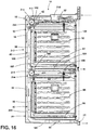
FIG. 16 is a cross-sectional view of the cooking appliance ofFIG. 1 , taken along line XVI-XVI; and -
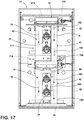
FIG. 17 is a cross-sectional view of the cooking appliance ofFIG. 1 , taken along line XVII-XVII. - For purposes of description herein the terms "upper," "lower," "right," "left," "rear," "front," "vertical," "horizontal," and derivatives thereof shall relate to the device as oriented in
FIG. 1 . However, it is to be understood that the device may assume various alternative orientations and step sequences, except where expressly specified to the contrary. It is also to be understood that the specific devices and processes illustrated in the attached drawings, and described in the following specification are simply exemplary embodiments of the inventive concepts defined in the appended claims. Hence, specific dimensions and other physical characteristics relating to the embodiments disclosed herein are not to be considered as limiting, unless the claims expressly state otherwise. - Referring now to
FIGS. 1-6 and12 ,reference numeral 10 generally refers to a cooling channel for aventilation system 12 of acooking appliance 14, where thecooling channel 10 serves to move coolingair 16 around portions of thecooking appliance 14. Thecooling channel 10 also allows for movement ofcavity air 18 from one ormore heating cavities 20 and into thecooling channel 10. Thiscavity air 18 can then be circulated through theventilation system 12 and removed from theappliance 14 through anair outlet 22 of theventilation system 12. According to various aspects of the device, thecooking appliance 14 can include ahousing 24 having at least oneheating cavity 20 defined therein. Aheat source 26 is disposed within thehousing 24 and is placed in thermal communication with theheating cavity 20. Thecooling channel 10 is disposed proximate at least onesidewall 28, typically aback wall 30, of thehousing 24 and is typically positioned at or near anexterior surface 32 of thehousing 24. Ablower 34 for theventilation system 12 of thecooking appliance 14 is disposed proximate thehousing 24. Theblower 34 selectively operates to move coolingair 16 through thecooling channel 10 and to theair outlet 22. Thecooling channel 10 is typically defined between thehousing 24 and achannel cover 44 attached to thehousing 24. Avent aperture 36 is positioned within thehousing 24 and extends through thesidewall 28 between theheating cavity 20 and aventilation channel 42. - The
ventilation channel 42, in certain aspects of the device, can include a narrowedportion 38 that is positioned near or proximate thevent aperture 36. During operation of theblower 34, the narrowedportion 38 defines a low static-pressure region 40 of theventilation channel 42. This low static-pressure region 40 serves to draw orsuction cavity air 18 from within theheating cavity 20. Thissuction 82 generated by the low static-pressure region 40 directs thecavity air 18 into theventilation channel 42 via thevent aperture 36. After leaving thevent aperture 36, thecavity air 18 is combined with thecooling air 16 within thecooling channel 10. In various aspects of the device, thecavity air 18 and thecooling air 16 are combined within adownstream portion 50 of thecooling channel 10. Typically, theventilation channel 42 is at least partially disposed within the coolingchannel 10. Theventilation channel 42 extends from thevent aperture 36 to the downstream location ordownstream portion 50. - This
downstream portion 50 is typically distal from thevent aperture 36, such as an area beneath thehousing 24 and near theair outlet 22. - According to various aspects of the device, the
ventilation channel 42 is a substantially closed duct that separates thecavity air 18 from the coolingair 16 within the coolingchannel 10. The coolingchannel 10 serves to cool various components of theappliance 14 that are disposed within theback wall 30 and at least partially disposed within the coolingchannel 10. These components can includevarious heat sources 26 and other portions of theappliance 14. Typically, thecavity air 18 can include grease, debris, particulate matter and other cooking byproducts. These cooking byproducts are ventilated from theheating cavity 20 and theappliance 14. These cooking byproducts also are separated from the heat sources 26 (such as convection fan 290) and other components of theappliance 14 contained within the coolingchannel 10. The cooking byproducts can clog or otherwise degrade the performance of these components. Accordingly, the use of theventilation channel 42 allows for movement of thecavity air 18 through the coolingchannel 10, but also maintains thecavity air 18 separate from the coolingair 16 and the components of theappliance 14. - Referring again to
FIGS. 2-6 , the narrowedportion 38 of theventilation channel 42 can be defined by a deflectingbody 60 that is disposed within theventilation channel 42. In this manner, the deflectingbody 60 is positioned within theventilation channel 42 and occupies at least a portion of theventilation channel 42 near thevent aperture 36. Thecavity air 18 moving through theventilation channel 42 and past the deflectingbodies 60 is caused to move faster around the deflectingbodies 60, thereby creating the low static-pressure region 40 in theventilation channel 42 at thevent aperture 36. This acceleration of the coolingair 16 causes a Venturi-effect section 120 within theventilation channel 42 that forms the low static-pressure region 40 at thevent aperture 36. As a result of the low static-pressure region 40,cavity air 18 is suctioned from theheating cavity 20 and into the low static-pressure region 40 at theventilation channel 42 via thevent aperture 36. Thissuction 82 is generated by the tendency of air in the low static-pressure region 40 to equalize or normalize in static pressure relative to other areas of theventilation channel 42. - The deflecting
bodies 60 that form the narrowedportion 38 of theventilation channel 42 can be made to have different cross sections that are formed by attaching the deflectingbodies 60 inside theventilation channel 42. Shapes of the deflectingbodies 60 can include, but are not limited to, triangles, wedges, arcuate shapes, undulating shapes, irregular shapes, combinations thereof, and other similar shapes that can define the narrowedportion 38 of theventilation channel 42. As discussed above, the narrowedportion 38 of theventilation channel 42 serves to create a Venturi-effect section 120 within the low static-pressure region 40 that accelerates the coolingair 16 at thevent aperture 36 of theventilation channel 42. As discussed previously, the low static-pressure region 40 of theventilation channel 42 creates the Venturi effect that serves to drawcavity air 18 out from theheating cavity 20 and through thevent aperture 36 and into theventilation channel 42 near the deflectingbodies 60. - Referring again to
FIGS. 4-7 , according to an exemplary aspect of the device, the deflectingbody 60 can include a leadingportion 62 that includes asteep transition 64. This leadingportion 62 serves to quickly accelerate thecavity air 18 to define the low static-pressure region 40. A trailingportion 66 can be positioned downstream of the leadingportion 62 and can include agradual transition 68. Thisgradual transition 68 serves to gradually increase the static pressure so that at least somesuction 82 is generated along the length of the trailingportion 66 of the deflectingbody 60. Thisgradual transition 68 of the trailingportion 66 also serves to better combine the various streams ofcavity air 18, and also serves to better combine thecavity air 18 with the coolingair 16 at thedownstream portion 50 in a generallylaminar transition 70. The use of thegradual transition 68 of the trailingportion 66 serves to limit the turbulence generated by the movement of thecavity air 18 into theventilation channel 42. The deflectingbody 60 can also include asuction gap 72 that is defined between the leading and trailingportions suction gap 72 allows for better movement of thecavity air 18 through thevent aperture 36 and into theventilation channel 42. In this manner, thesuction gap 72 can at least partially define thevent aperture 36. In various embodiments, the trailingportion 66 can define astep 74 that is a narrowedtop edge 76 of the trailingportion 66. The narrowedtop edge 76 steps inward from the leadingportion 62 so that thestep 74 defines at least a portion of the Venturi-effect section 120 of thevent aperture 36. - According to various aspects of the device, the narrowed
portion 38 of theventilation channel 42 can also be formed through manipulating the shape ofboundary walls 80 of the coolingchannel 10 in the area of thevent apertures 36. Theboundary walls 80 of the coolingchannel 10 can be bent or deformed inward or flattened to a thinner profile to form the narrowedportion 38 of the coolingchannel 10. Making the coolingchannel 10 narrower can result in the low static-pressure region 40 that generates the Venturi-effect section 120 tosuction cavity air 18 through thevent aperture 36 and into theventilation channel 42. - According to the various aspects of the device, where the deflecting
body 60 is a separate body installed within theventilation channel 42, the deflectingbody 60 typically surrounds at least a portion of thevent aperture 36. Through this placement, the Venturi effect generated by the deflectingbody 60 can causesuction 82 through thevent aperture 36 for drawingcavity air 18 from theheating cavity 20 and into theventilation channel 42. In various aspects of the device, the amount ofsuction 82 created in the low static-pressure region 40 can be regulated by the operating speed of theblower 34, or by a pulse-type operation of theblower 34. - Referring again to
FIGS. 1-6 ,12 and15-17 , thecooking appliance 14 can also include a second orlower heating cavity 90 that is positioned within thehousing 24 and typically below the primary orupper heating cavity 92. A secondary orlower vent aperture 94 can serve thelower heating cavity 90 and can extend through thelower housing 96 between thelower heating cavity 90 and theventilation channel 42. In this manner, theventilation channel 42 can include a secondary and, typically, a lower narrowedportion 98 disposed near or proximate thelower vent aperture 94. During operation of theblower 34, the lower narrowedportion 98 defines another of the low static-pressure regions 40 of theventilation channel 42. This second low static-pressure region 40 forms another Venturi-effect section 120 of theventilation channel 42 that draws secondary cavity air orlower cavity air 100 from thelower heating cavity 90. Thislower cavity air 100 is directed from thelower heating cavity 90 and into theventilation channel 42 via thelower vent aperture 94. Thislower cavity air 100 is then combined within theventilation channel 42 with thecavity air 18 from theupper heating cavity 92. Thelower cavity air 100 and thecavity air 18 can then be combined with the coolingair 16 at thedownstream portion 50 of the coolingchannel 10. - According to the various aspects of the device, the
ventilation channel 42 extends continuously between theupper vent aperture 102 and thelower vent aperture 94 and corresponding upper and lower narrowedportions cooking appliance 14 typically includes asingle ventilation channel 42 that serves each of theupper heating cavity 92 andlower heating cavity 90, which can also be referred to as the upper andlower heating cavities additional heating cavities 20 where aparticular cooking appliance 14 can include three ormore heating cavities 20. In an exemplary embodiment, fourheating cavities 20 are shown inFIG. 2 . In such an embodiment, theventilation channel 42 extends past eachvent aperture 36 of thevarious heating cavities 20. Accordingly, the cooking byproducts from thevarious heating cavities 20 are separated from the remainder of the coolingchannel 10, and, in turn, the coolingair 16 and the various components of theappliance 14 that are cooled by the coolingair 16. While theheating cavities 20 are described herein as vertically oriented, horizontal orientations ofheating cavities 20 and other directional orientations are contemplated. - Referring again to
FIGS. 1-6 ,12 and15-17 , wheremultiple heating cavities 20 are included within thecooking appliance 14, theventilation channel 42 can extend past eachvent aperture 36 and corresponding narrowedportions 38 of thevarious heating cavities 20. In the various aspects of the device, asingle blower 34 can be utilized within thecooking appliance 14 to movecavity air 18 through theventilation channel 42. In certain embodiments, asingle blower 34 can be used to movecavity air 18 throughseveral vent apertures 36 and corresponding narrowedportions 38. While anappliance 14 havingmultiple heating cavities 20 will typically havemultiple blowers 34, one of theseblowers 34 may be utilized for removingcavity air 18 from theheating cavities 20 and into theventilation channel 42 that serves severalcorresponding heating cavities 20. It is also contemplated thatmultiple blowers 34 can be used to movecavity air 18 frommultiple heating cavities 20 through thesingle ventilation channel 42. Wheremultiple blowers 34 are used, eachblower 34 is typically positioned at separate positions of theventilation channel 42 or can be connected to separate anddedicated ventilation channels 42. These separate anddedicated ventilation channels 42 are disposed within the coolingchannel 10 and terminate at thedownstream portion 50 of the coolingchannel 10. Typically asingle blower 34 will serve acommon ventilation channel 42 that can provide for efficient movement of the various streams ofcavity air 18 that are drawn or suctioned from thevarious heating cavities 20 of theappliance 14 and moved to thedownstream portion 50 to be combined with the coolingair 16 in the coolingchannel 10. - In various aspects of the device, as exemplified in
FIGS. 15-17 , thevarious heating cavities 20 typically include avent aperture 36 that leads into theventilation channel 42. Thevent aperture 36 can be positioned within atop wall 52 of theheating cavity 20. Theventilation channel 42 then extends from thevent aperture 36 within thetop wall 52 and extends through theventilation channel 42 and into thelow pressure space 182 of thecorresponding blower 34. This configuration can be referred to as a top-reverse configuration 112 where thecavity air 18 is moved through thetop wall 52 of theheating cavity 20 and toward the remainder of theventilation channel 42 that is positioned near theback wall 30 of theappliance 14. In other aspects of theappliance 14, thevent aperture 36 can be located within aback wall 30 of theheating cavity 20. During operation of ablower 34,cavity air 18 is moved through thevent aperture 36 in theback wall 30 and is moved through theventilation channel 42 toward alow pressure space 182 of ablower 34 positioned below theheating cavity 20. This configuration can be referred to as a back-reverse configuration 114. - In the top-
reverse configuration 112, theblower 34 that serves therespective heating cavity 20 forms thelow pressure space 182 that moves thecavity air 18 from therespective heating cavity 20. This configuration is typically seen inappliances 14 that have asingle heating cavity 20 as well as other configurations. The back-reverse configuration 114 is typically found inappliances 14 having at least anupper heating cavity 92 and alower heating cavity 90. In the back-reverse configuration 114, thelower blower 216 serves to drawcavity air 18 from theupper heating cavity 92. In this configuration, thevent aperture 36 within theupper heating cavity 92 is positioned within aback wall 30 of theupper heating cavity 92. Theventilation channel 42 extends from thevent aperture 36 within theback wall 30 of theupper heating cavity 92 and extends downward to thelow pressure space 182 of thelower blower 216. Thelower blower 216 then moves thecavity air 18 from theupper heating cavity 92 through the remainder of theventilation channel 42 and toward theair outlet 22 for theappliance 14. - According to various aspects of the device, where the
appliance 14 includesmultiple heating cavities 20, thevarious heating cavities 20 can include different ventilation configurations. These ventilation configurations can include the top-reverse configuration 112 or the back-reverse configuration 114 described above. In anappliance 14 havingmultiple heating cavities 20, one of theheating cavities 20 may include a conventional forward ventilation configuration that is known in the art. The remainingheating cavities 20 will typically include the back-reverse configuration 114, the top-reverse configuration 112, or a variation of these novel configurations, as disclosed herein. In various aspects of the device, it is also contemplated that one of theheating cavities 20 may include novent apertures 36. - Referring now to
FIGS. 4-7 , various aspects of thecooking appliance 14 can include upper andlower heating cavities lower vent apertures blower 34 for theventilation system 12, the narrowedportions 38 of the ventilation channel 42can create a Venturi-effect section 120 of theventilation channel 42 at each of the upper andlower vent apertures upper cavity air 108 is drawn from theupper heating cavity 92 and through theupper vent aperture 102. Thisupper cavity air 108 is then moved through the narrowedportion 38 of theventilation channel 42 at thelower vent aperture 94. Thelower vent aperture 94 can include a deflectingbody 60 in the form of acover member 130 that extends around at least a portion of thelower vent aperture 94. Thiscover member 130 can include anaerodynamic deflector 132 that divertsupper cavity air 108 from theupper heating cavity 92 to defect around thelower vent aperture 94 at thelower heating cavity 90. Theaerodynamic deflector 132 also generates the low static-pressure region 40 at thelower vent aperture 94. - Referring again to
FIGS. 4-7 , thisaerodynamic deflector 132 extends downstream of thelower vent aperture 94 and serves to prevent infiltration ofupper cavity air 108 into thelower vent aperture 94. In this manner, various particles, fumes, debris, and other cooking byproducts that may be contained within theupper cavity air 108 are prevented from entering into thelower heating cavity 90 via thelower vent aperture 94. Infiltration of theupper cavity air 108 infiltrating into thelower vent aperture 94 may occur in instances when a door of theupper heating cavity 92 is rapidly closed or slammed. This rapid closure of the door can increase the air pressure within theventilation channel 42. This increased air pressure may tend theupper cavity air 108 toward thelower vent aperture 94. Using theaerodynamic deflector 132 that extends around thelower vent aperture 94, contamination between the upper andlower heating cavities aerodynamic deflector 132. - Referring again to
FIG. 7 , theaerodynamic deflector 132 surrounds thelower vent aperture 94 and includes a taperedtransition 140 that defines the low static-pressure region 40 and generates Venturi-effect suction 82 that serves to introducelower cavity air 100 from thelower heating cavity 90. Thelower cavity air 100 then combines with theupper cavity air 108 and subsequently combines with the remainder of coolingair 16 at a position downstream of thelower vent aperture 94. Thistapered transition 140 of theaerodynamic deflector 132 forms anaccelerated air region 142 that utilizes the Venturi effect to promote thesuction 82 or outflow oflower cavity air 100 from thelower heating cavity 90 through thelower vent aperture 94 and into theventilation channel 42. Thistapered transition 140, as discussed above, also prevents the inflow ofupper cavity air 108 into thelower vent aperture 94. - Referring again to
FIG. 7 , the use of theaerodynamic deflector 132 also creates a pressure differential between the areas within and areas around theaerodynamic deflector 132. Thistapered transition 140 can assist in creating one of low static-pressure regions 40 near thelower vent aperture 94. In this manner, thelower cavity air 100 moves through thelower vent aperture 94 and moves in anexhaust direction 144 to combine withupper cavity air 108 from theupper vent aperture 102. These streams of upper andlower cavity air downstream portion 50 of the coolingchannel 10 and are combined with the coolingair 16 that is moved toward theair outlet 22. According to various aspects of the device, theaerodynamic deflector 132 typically includes anupper deflecting section 146 that leads into the taperedtransition 140. Thisupper deflecting section 146 generates a low static-pressure region 40 in the area outside thetapered transition 140. - The low static-
pressure region 40 assists in drawing air from thelower vent aperture 94 and also assists in forming anair curtain 154 that prevents infiltration ofupper cavity air 108 into thelower vent aperture 94. It is also contemplated that theaerodynamic deflector 132 positioned at thelower vent aperture 94 can extend the full depth of theventilation channel 42. In this manner, the area defined inside of theaerodynamic deflector 132 that includes thelower vent aperture 94 and the tapered insideportion 150 can be substantially contained inside theaerodynamic deflector 132. Atapered outlet 156 at the end of theoutlet extension 152 may provide the only aperture through theaerodynamic deflector 132 into theventilation channel 42. In this manner, theaerodynamic deflector 132 creates asuction path 158 that extends from inside thelower heating cavity 90, through thelower vent aperture 94 and through the tapered insideportion 150 of theaerodynamic deflector 132 and out the taperedoutlet 156 of theaerodynamic deflector 132. Again, this region formed by theaerodynamic deflector 132 prevents infiltration ofupper cavity air 108 into thelower vent aperture 94 and into thelower heating cavity 90. - Referring now to
FIGS. 1-8 , theventilation system 12 for thecooking appliance 14 can include thehousing 24 that surrounds at least oneheating cavity 20, where thehousing 24 includes asidewall 28 that at least partially defines one ormore heating cavities 20. Theouter ventilation path 170 that includes the coolingchannel 10 extends around at least a portion of theexterior surface 32 of thehousing 24. Again, the coolingchannel 10 is typically disposed proximate thesidewall 28 of thehousing 24 and at theexterior surface 32 of thehousing 24 and is covered by achannel cover 44 attached to thehousing 24. Theblower 34 for theventilation system 12 is selectively operable to move coolingair 16 through the coolingchannel 10 and to theair outlet 22. - Referring again to
FIGS. 1-6 ,12 and15-17 , typically, theair outlet 22 is positioned at abase 180 of thehousing 24 and directs air outward from thecooking appliance 14. At least one low static-pressure region 40 is defined within the coolingchannel 10 at eachblower 34. Eachblower 34 defines alow pressure space 182 within the area where coolingair 16 enters into theblower 34. Theventilation channel 42 extends from thevent aperture 36 and into thelow pressure space 182. In this manner, theventilation channel 42 utilizes thislow pressure space 182 to drawcavity air 18 from theheating cavity 20, through thevent aperture 36 and toward theblower 34. Accordingly, thelow pressure space 182 generated by theblower 34 draws coolingair 16 through the coolingchannel 10 and contemporaneously or simultaneously drawscavity air 18 through theventilation channel 42. - In various aspects of the device, the low static-
pressure region 40 supplements thelow pressure space 182 of theblower 34. As discussed above, the low static-pressure region 40 includes avent aperture 36 that extends through thesidewall 28 between theheating cavity 20 and theventilation channel 42. The narrowedportion 38 of theventilation channel 42 at least partially defines the low static-pressure region 40. The low static-pressure region 40 works in conjunction with thelow pressure space 182 of theblower 34 to selectively draw orsuction cavity air 18 from theheating cavity 20 and into the low static-pressure region 40 of theventilation channel 42 via thevent aperture 36. Thecavity air 18 that is suctioned from theheating cavity 20 combines with the coolingair 16 in the coolingchannel 10 and typically at adownstream portion 50 of the coolingchannel 10. - In certain embodiments of the device, as exemplified in
FIGS. 12 and15-17 , theventilation system 12 for theappliance 14 can serve thesecond heating cavity 20 that is positioned within thehousing 24 and typically below theprimary heating cavity 20. Again, these can be referred to as the upper andlower heating cavities housing 24. Alower vent aperture 94 extends through thehousing 24 between thelower heating cavity 90 and theventilation channel 42 that is disposed within the coolingchannel 10. Theventilation channel 42 includes the lower narrowedportion 98 that is disposed proximate or near thelower vent aperture 94. The lower narrowedportion 98 selectively defines one of the low static-pressure regions 40 of theventilation channel 42. This low static-pressure region 40, in conjunction with thelow pressure space 182 of theblower 34, serves to draw or suctionlower cavity air 100 from thelower heating cavity 90 and directs thelower cavity air 100 into theventilation channel 42 via thelower vent aperture 94. In this manner, thelower cavity air 100 is combined with theupper cavity air 108 from theupper heating cavity 92. These streams of upper andlower cavity air air 16 at thedownstream portion 50 of the coolingchannel 10. As discussed above, the use of the narrowedportions 38 of theventilation channel 42 operate with theblower 34 to generate the lower static-pressure regions 40 that can be repeated for various numbers and configurations ofheating cavities 20. - Referring now to
FIG. 11 , in certain aspects of the device, portions of theventilation system 12, and in particular, theventilation channel 42 can be positioned within the coolingchannel 10 and between an exterior of thesidewall 28 of thehousing 24 and aninsulation layer 190 that is positioned within the coolingchannel 10. Thisinsulation layer 190 serves to limit the transfer of heat between theventilation channel 42 and the coolingair 16 within the remainder of the coolingchannel 10. Noise from the one ormore blowers 34,various convection fans 290, the coolingchannel 10,heat sources 26, and other aspects of thecooking appliance 14 can also be dampened through the inclusion of theinsulation layer 190 that surrounds at least a portion of theventilation channel 42. - Referring again to
FIGS. 2 ,11 and12 , the positioning of theventilation channel 42 between thehousing 24 and theinsulation layer 190 maintains the upper andlower cavity air insulation layer 190 prevents significant heat loss with respect to the upper andlower cavity air air 16. Cooling of this air may result in condensation forming within the coolingchannel 10 and theventilation channel 42. By including theinsulation layer 190 that extends around theventilation channel 42, the temperature of the coolingair 16 and the upper andlower cavity air ventilation system 12 for theappliance 14. Additionally, cool air that may be located around theinsulation layer 190 and within the coolingchannel 10 is substantially prevented from causing a transfer of thermal energy from theventilation channel 42 through theinsulation layer 190 and to the outer areas of the coolingchannel 10 surrounding theinsulation layer 190. Again, by maintaining the coolingair 16 within the coolingchannel 10 and the upper andlower cavity air ventilation channel 42, at a relatively consistent temperature, condensation within and around theventilation system 12 can be kept a minimum or substantially prevented. - According to various aspects of the device, the
insulation layer 190 can be made of batting-type insulation, roll-type insulation, foam-insulation, spray-insulation, combinations thereof, and other similar insulating materials. - Referring now to
FIGS. 2 and8-12 , theventilation system 12 for thecooking appliance 14 includes anouter ventilation path 170 that extends around thehousing 24 and that can include the coolingchannel 10. Thisouter ventilation path 170 can draw coolingair 16 from asuperior portion 210 of theouter ventilation path 170 that is typically positioned above theupper heating cavity 92. The coolingair 16 can be recirculated air that is located around thehousing 24 or can be fresh air collected from in front of theheating appliance 14. The movement of the coolingair 16 through theouter ventilation path 170 is generated by thelow pressure space 182 of theblower 34. During operation of theblower 34, thelow pressure space 182 draws or suctions coolingair 16 into and through theblower 34. The coolingair 16 can then be moved through theblower 34 and to arearward portion 212 of thehousing 24 and toward theair outlet 22. As discussed above, theventilation channel 42 also utilizes thelow pressure space 182 of theblower 34. Theventilation channel 42 extends intolow pressure space 182. During operation of theblower 34, thelow pressure space 182 contemporaneously draws coolingair 16 from thesuperior portion 210 and drawscavity air 18 through thevent aperture 36 and into theventilation channel 42. Thecavity air 18, which is substantially separated from the coolingair 16, moves into theventilation channel 42 to be moved past each of the upper andlower vent apertures portions 38 that generate the low static-pressure regions 40. - As discussed above, the
ventilation system 12 can include asingle blower 34 that moves coolingair 16 through the coolingchannel 10 and contemporaneously movescavity air 18 through theventilation channel 42. Theventilation system 12 can also includemultiple blowers 34 such as an upper andlower blower air 16 through various portions of theouter ventilation path 170. Where twoblowers 34 are present, anupper blower 214 can typically draw coolingair 16 around theupper housing 104. Thelower blower 216 will typically be dedicated for use with respect to thelower housing 96 such that coolingair 16 is drawn by thelower blower 216 around thelower housing 96. In embodiments utilizingmultiple blowers 34, it is contemplated that the upper andlower blowers cavity air 18 through theventilation channel 42 and to also create the low static-pressure regions 40 that are formed through the narrowedportions 38 of theventilation channel 42. - Referring again to
FIGS. 2 ,8-12 and15-17 , the one ormore blowers 34 of theventilation system 12 for thecooking appliance 14 can be in the form of across flow blower 34. Across flow blower 34 typically operates along a horizontalrotational axis 230 and draws air from anupstream region 232 and directs that air through operation of theblower 34, typically in a differentangular direction 234 normal to therotational axis 230 of thecross flow blower 34. As discussed above, thecooking appliance 14 can include one or multiplecross flow blowers 34 that can be used individually or in conjunction to move coolingair 16 through theventilation system 12 for thecooking appliance 14. Also, thelow pressure space 182 of theblower 34 is within theupstream region 232 of theblower 34. Thecross flow blower 34 has a width that extends across most, if not all, of the coolingchannel 10. A narrow portion of thecross flow blower 34 is configured to receive theventilation channel 42. Accordingly, thelow pressure space 182 formed by theblower 34 acts to draw coolingair 16 through the coolingchannel 10 and contemporaneously drawscavity air 18 through theventilation channel 42. Thissuction 82 through the coolingchannel 10 and through theventilation channel 42 can be performed through the use of a singlelow pressure space 182 formed by asingle blower 34. - Referring again to
FIGS. 2 and8-10 , the upper andlower blowers ventilation system 12 can be positioned such that theupper blower 214 is positioned near theupper heating cavity 92 and thelower blower 216 is positioned near the second orlower heating cavity 90. The upper andlower blowers dedicated cooling channels 10 that extend around the upper andlower heating cavities lower blower 216 is used to drawupper cavity air 108 from theupper heating cavity 92, theventilation channel 42 can include atransition portion 240 that is positioned at thelower blower 216. Operation of at least thelower blower 216 forms anair acceleration section 242 within thelow pressure space 182 of thelower blower 216. Thislow pressure space 182 draws coolingair 16 from thesuperior portion 210 of theouter ventilation path 170 above thelower heating cavity 90 and also drawsupper cavity air 108 from theupper heating cavity 92. As discussed above, thelower blower 216 extends across a large portion of the coolingchannel 10. Thetransition portion 240 of theventilation channel 42 typically occupies only a small portion of the width of thelower blower 216. Thelower blower 216 at thetransition portion 240 moves theupper cavity air 108 through theventilation channel 42 that is positioned within thelow pressure space 182, through theblower 34 and into alower section 244 of theventilation channel 42 and toward theair outlet 22. - According to various aspects of the device, as exemplified in
FIGS. 10 ,12 and15-17 , thetransition portion 240 of thelower blower 216 can receivecavity air 18 from each of the upper andlower heating cavities ventilation channel 42 can extend from theupper heating cavity 92 via theupper vent aperture 102 that is disposed within theback wall 30 of theupper heating cavity 92. Theventilation channel 42 then extends from thisupper vent aperture 102 and through theventilation channel 42 that extends into thelow pressure space 182 defined by thelower blower 216. Simultaneously, asecond ventilation channel 220 can extend from alower vent aperture 94 that is disposed within atop wall 52 of thelower heating cavity 90. Thesecond ventilation channel 220 extends from thelower vent aperture 94 and through thesecond ventilation channel 220 and extends into thelow pressure space 182 of thelower blower 216. In this manner, thelow pressure space 182 of thelower blower 216 can be used to draw upper andlower cavity air ventilation channel 42 and thesecond ventilation channel 220. At the same time, thelower blower 216 can also be used to draw coolingair 16 around at least thelower heating cavity 90. - Referring again to
FIG. 12 , theventilation channel 42, thesecond ventilation channel 220, and other similar ventilation channels that may serveadditional heating cavities 20 define a substantially self-contained venting system for thevarious heating cavities 20 of theappliance 14. This vent system is contained within the coolingchannel 10 of theappliance 14 and is operated by thevarious blowers 34 of theventilation system 12. In this manner, thevarious blowers 34 of theventilation system 12 serve to operate, contemporaneously, the movement of coolingair 16 through thevarious cooling channels 10 and also the movement ofcavity air 18 through thevarious ventilation channels 42. Through the use of these integrated and contemporaneously-operating systems,additional blowers 34 are not necessary for separately operating the movement ofcavity air 18 and the movement of coolingair 16 through theappliance 14. - In various aspects of the device, the upper and
lower blowers cavity air 18 from theupper heating cavity 92. In such an embodiment, theventilation channel 42 extends from theupper vent aperture 102 that is defined within thetop wall 52 of theupper heating cavity 92. Theventilation channel 42 extends to thelow pressure space 182 of theupper blower 214. Theupper blower 214 operates to move theupper cavity air 108 through theventilation channel 42 along theback wall 30 of theupper heating cavity 92 and toward thelower blower 216. In this embodiment, thetransition portion 240 acts as a booster for assisting the movement ofupper cavity air 108 through theventilation channel 42 and toward theair outlet 22. In this embodiment, thetransition portion 240 receives theupper cavity air 108 from theupper blower 214. Thelow pressure space 182 of thelower blower 216 increases the movement of theupper cavity air 108 through theventilation channel 42 and pushes theupper cavity air 108 through thetransition portion 240 and toward theair outlet 22. In this configuration, the upper andlower blowers upper cavity air 108 through theventilation channel 42 and to theair outlet 22. - Referring again to
FIGS. 8-10 , theair acceleration section 242 that is defined by thelow pressure space 182 of thelower blower 216 may also be partially formed by a narrowedtransition 250 of theventilation channel 42 that leads into thelower blower 216. By decreasing the cross-sectional size of theventilation channel 42 at thelower blower 216, there is a decreased static pressure in theventilation channel 42 leading into thelower blower 216. This, in addition to thelow pressure space 182 of thelower blower 216, causes thecavity air 18 to accelerate as thecavity air 18 enters into thelower blower 216. Theventilation channel 42 then opens up at the high pressure outlet side 251 of thelower blower 216. In this manner, the narrow stream ofcavity air 18 entering theblower 34 can be maintained within theventilation channel 42 as thecavity air 18 passes into a wider opening of thelower section 244 of theventilation channel 42. In this configuration, a certain amount of coolingair 16 may infiltrate into thelower section 244 of theventilation channel 42. The infiltration of coolingair 16 can assist in containing thecavity air 18 within theventilation channel 42 as thecavity air 18 passes through thetransition portion 240 and theblower 34. Conversely, thecavity air 18, which typically includes some cooking byproducts, is substantially prevented from leaving theventilation channel 42. Additionally,lower blower 216 generates a higher static pressure at theoutlet side 254 of thelower blower 216. The increased static pressure generated at thelower blower 216 assists thelower blower 216 in moving thecavity air 18 from theupstream region 232 of theventilation channel 42, through thetransition portion 240 and to thelower section 244 of the coolingchannel 10 and also substantially preventing infiltration of thecavity air 18 into portions of the coolingchannel 10 outside of theventilation channel 42. - According to various aspects of the device, as exemplified in
FIGS. 12 and15-17 , thelower blower 216 can also serve as theonly blower 34 of the plurality ofblowers 34 for movingcavity air 18 through theventilation channel 42. In such an embodiment, thelower blower 216 can be activated independent of theupper blower 214 to drawcavity air 18 into theventilation channel 42. In addition to moving thecavity air 18, thelower blower 216 also moves coolingair 16, typically, from an area between the upper andlower housings - Referring again to
FIGS. 2 ,8 and9 , theupstream region 232 of theventilation channel 42 tapers to the narrowedtransition 250 in the form of a taperedarea 270 that is disposed within thelow pressure space 182 within thetransition portion 240. When thecavity air 18 is moved through thelower blower 216, thelower blower 216 directs thiscavity air 18 into thelower section 244 of theventilation channel 42. Thelower section 244 of theventilation channel 42 extends from anenlarged portion 272 near theoutlet side 254 of thelower blower 216 and again transitions down to a taperedlower end 274. As discussed above, theenlarged portion 272 assists in maintaining thecavity air 18 within theventilation channel 42. This helps to move thecavity air 18 toward theair outlet 22 for thecooking appliance 14. - Through the use of the
transition portion 240, thecooking appliance 14 is able to movecavity air 18 through theventilation channel 42 via operation of only thelower blower 216 or through operation of the upper andlower blowers lower blower 216 can be intermittently activated to assist in movingcavity air 18 through theventilation channel 42 into theair outlet 22. Use of the upper andlower blowers pressure regions 40 that are located at the upper andlower vent apertures lower cavity air lower heating cavities additional suction 82 is needed through the upper andlower vent apertures lower blowers portions 38 of theventilation channel 42 and further decrease the static pressure at the upper andlower vent apertures suction 82 from the upper andlower heating cavities lower vent apertures ventilation channel 42. - Referring again to
FIGS. 8-10 , because thelower blower 216 is positioned between the upper andlower housings cooking appliance 14, there may be a relatively long run of ductwork between thistransition portion 240 and theair outlet 22. This long run can, in certain instances, result in a pressure drop within theventilation channel 42 at or near thelower blower 216. This pressure drop results inless suction 82 and the slower movement ofcavity air 18 towards theair outlet 22. The use of thelow pressure space 182 of thelower blower 216 can assist in increasing the flow ofcavity air 18. Additionally, the inclusion of thetransition portion 240 having the narrowedtransition 250 serves to increase thesuction 82 in this area by decreasing the static pressure. The use of this taperedtransition portion 240 serves to counteract the pressure drop that may be experienced, due to an excessive distance between thelower blower 216 and theair outlet 22. - Referring now to
FIGS. 13 and14 , eachheating cavity 20 of thecooking appliance 14 can utilize various pressure differentials to move air from theheating cavity 20 and into theventilation channel 42. According to various aspects of the device, theheating cavity 20 can include abaffle cover 280 that is disposed within theheating cavity 20 and proximate thevent aperture 36. Ahigh pressure space 282 can be defined between thebaffle cover 280 and thevent aperture 36. Thehigh pressure space 282 is configured to operate cooperatively with the low static-pressure region 40 defined within theventilation channel 42. The combination of thehigh pressure space 282 within theheating cavity 20 and the low static-pressure region 40 of theventilation channel 42 serves to drawcavity air 18 from theheating cavity 20 and direct thiscavity air 18 into theventilation channel 42 via thevent aperture 36. To form thishigh pressure space 282, thebaffle cover 280 is positioned in an offset relationship to aback surface 284 that defines theheating cavity 20. - Referring again to
FIGS. 13 and14 , thebaffle cover 280 can conceal aconvection fan 290 that is positioned behind thebaffle cover 280. During operation of theconvection fan 290, movement ofcavity air 18 within theheating cavity 20 generates thehigh pressure space 282 between thebaffle cover 280 and theback surface 284 of theheating cavity 20. To assist in forming thishigh pressure space 282, the plurality of directingchannels 292 are defined within thebaffle cover 280. These directingchannels 292 extend from theconvection fan 290 and to an area near thevent aperture 36 for theheating cavity 20. The plurality of directingchannels 292 cooperate with theconvection fan 290 and thevent aperture 36 to generate thehigh pressure space 282 that directs thecavity air 18 from theheating cavity 20 and into theventilation channel 42. Theconvection fan 290,baffle cover 280, directingchannels 292 and ventaperture 36 are positioned to maximize thehigh pressure space 282 such that thevent aperture 36 is positioned at or near this area ofhighest pressure 294 within theheating cavity 20. In this manner, thecavity air 18 is directed toward the area where thevent aperture 36 is located. Accordingly, the low static-pressure region 40 is able to more conveniently drawcavity air 18 through thevent aperture 36. The combination of thehigh pressure space 282 and the low static-pressure region 40 within theventilation channel 42 makes thesuction 82 for drawingcavity air 18 from theheating cavity 20 more efficient. According to various aspects of the device, this configuration of thebaffle cover 280 and theconvection fan 290 can be disposed within each of the plurality ofheating cavities 20 disposed within thecooking appliance 14. - Referring again to
FIGS. 13 and14 , the use of thebaffle cover 280 used in conjunction with theconvection fan 290 can increase, or make more efficient, thesuction 82 generated through thevent aperture 36 for drawingcavity air 18 into theventilation channel 42. This moreefficient suction 82 generated by the use of theconvection fan 290 can allow designers of theappliance 14 to decrease the size of thecross fan blower 34, or other blower types, that may be used within theventilation system 12 for theappliance 14. The use of thebaffle cover 280 can make thesuction 82 through thevent aperture 36 more efficient such that a singlecross fan blower 34 may be utilized for movingcavity air 18 through theventilation channel 42 and out theair outlet 22 for theappliance 14. - Referring again to
FIGS. 1-14 , thecooking appliance 14 can include theupper housing 104 that defines theupper heating cavity 92 and thelower housing 96 can define thelower heating cavity 90. In such an embodiment, the upper andlower housings housing 24 for thecooking appliance 14. Theouter ventilation path 170 of theventilation system 12 extends around at least a portion of the upper andlower housings air outlet 22. Within theouter ventilation path 170, theventilation channel 42 is located as a substantially enclosed duct that extends at least from theupper housing 104 to thelower housing 96 and to adownstream portion 50. Theupper vent aperture 102 extends through theupper housing 104 between theupper heating cavity 92 andventilation channel 42. Thelower vent aperture 94 extends through thelower housing 96 between thelower heating cavity 90 and theventilation channel 42. According to various aspects of the device, theventilation channel 42 extends at least between the upper andlower vent apertures lower deflecting bodies ventilation channel 42 proximate the upper andlower vent apertures bodies pressure regions 40 of the coolingchannel 10. Upper andlower blowers air 16 through theouter ventilation path 170. Operation of at least thelower blower 216 contemporaneously movescavity air 18 through theventilation channel 42 and coolingair 16 through theouter ventilation path 170 andvarious cooling channels 10. Operation of the at least oneblower 34 selectively defines thelow pressure spaces 182 and also defines various low static-pressure regions 40 that are positioned within theventilation channel 42, and in particular, at or near the upper andlower vent apertures pressure region 40 at theupper vent aperture 102, drawsupper cavity air 108 from theupper heating cavity 92 and into theventilation channel 42. The low static-pressure region 40 at thelower vent aperture 94 drawslower cavity air 100 from thelower heating cavity 90 and into theventilation channel 42. - Referring again to
FIGS. 1-7 , the low static-pressure region 40 at thelower vent aperture 94 draws thelower cavity air 100 through thelower vent aperture 94 and in anexhaust direction 144 to define anair curtain 154. Theair curtain 154 directs theupper cavity air 108 from theupper vent aperture 102 from an upstream area of theventilation channel 42 toward theair outlet 22 and away from thelower vent aperture 94. Accordingly, infiltration of odors, particulate matter, cooking byproducts and other material from theupper heating cavity 92 can be prevented from entering into thelower heating cavity 90 via thelower vent aperture 94. - As discussed above, the
ventilation channel 42 that extends between the upper andlower housings channel 10 and between thehousing 24 and aninsulation layer 190 that extends around thehousing 24. The use of theinsulation layer 190 serves to maintain the separated portions of the coolingair 16, theupper cavity air 108 and thelower cavity air 100 at a relatively consistent temperature to prevent condensation and the accumulation of moisture within theventilation system 12 of thecooking appliance 14. - As exemplified in
FIGS. 8-12 , the at least oneblower 34, such as thelower blower 216, can be positioned proximate thelower heating cavity 90. In certain embodiments, theventilation channel 42 includes atransition portion 240 that is positioned proximate the at least oneblower 34. Operation of the at least oneblower 34 forms thelow pressure space 182 that effectively generates anair acceleration section 242 that drawsupper cavity air 108 from theupper heating cavity 92 and moves the upper cavity air 108 (separately moved within the ventilation channel 42) into alower section 244 of theventilation channel 42 and toward theair outlet 22. Operation of the at least oneblower 34 in thistransition portion 240 forms thelow pressure space 182 that decreases the static pressure in this area and causes an acceleration of thecavity air 18 into the at least oneblower 34 and toward alower section 244 of theventilation channel 42. The use of thetransition portion 240 of theventilation channel 42 serves to limit the effect of any pressure drop that may occur within thecavity air 18 as the at least oneblower 34 moves thecavity air 18 toward theair outlet 22.
Claims (15)
- A cooking appliance (14) comprising:a housing (24) having a heating cavity (20) defined therein, wherein a heat source (26) is in thermal communication with the heating cavity (20);a cooling channel (10) disposed proximate a sidewall (28) of the housing (24);a blower (34) that selectively operates to move at least cooling air (16) through the cooling channel (10) and to an air outlet (22);a vent aperture (36) extending through the sidewall (28) between the heating cavity (20) and a ventilation channel (42), wherein the ventilation channel (42) includes a narrowed portion (38) proximate the vent aperture (36), wherein during operation of the blower (34), the narrowed portion (38) defines a low static-pressure region (40) of the ventilation channel (42) that draws cavity air (18) from the heating cavity (20) and directs the cavity air (18) into the ventilation channel (42) to be combined with the cooling air (16).
- The cooking appliance (14) of claim 1, wherein the cavity air (18) and the cooling air (16) are combined within a downstream portion (50) of the cooling channel (10) that is distal from the vent aperture (36).
- The cooking appliance (14) of any one or more of claims 1-2, further comprising:
a deflecting body (60) disposed within the ventilation channel (42), wherein the deflecting body (60) at least partially defines the narrowed portion (38). - The cooking appliance (14) of claim 3, wherein the deflecting body (60) at least partially surrounds the vent aperture (36).
- The cooking appliance (14) of any one or more of claims 1-4, further comprising:a second heating cavity (20) positioned within the housing (24) and below the heating cavity (20);a second vent aperture (36) extending through the housing (24) between the second heating cavity (20) and the ventilation channel (42), wherein the ventilation channel (42) includes a second narrowed portion (38) proximate the secondary vent aperture (36),
- The cooking appliance (14) of claim 5, wherein during operation of the blower (34), the second narrowed portion (38) defines a low static-pressure region (40) of the second narrowed portion (38) of the ventilation channel (42) that draws secondary cavity air (18) from the second heating cavity (20) and directs the secondary cavity air (18) into the ventilation channel (42) to be combined with the cooling air (16).
- The cooking appliance (14) of claim 5, wherein the low static-pressure region (40) of the second narrowed portion (38) draws the secondary cavity air (18) through the secondary vent aperture (36) in an exhaust direction (144) to define an air curtain (154).
- The cooking appliance (14) of claim 7, wherein the air curtain (154) directs cavity air (18) from the vent aperture (36) of the heating cavity (20) toward the air outlet (22) and away from the secondary vent aperture (36).
- The cooking appliance (14) of any one or more of claims 1-8, further comprising:
an insulation layer (190) surrounding at least a portion of the housing (24), wherein the ventilation channel (42) is positioned between the sidewall (28) of the housing (24) and the insulation layer (190). - The cooking appliance (14) of any one or more of claims 1-9, where the blower (34) includes an upper blower (214) positioned above the heating cavity (20) and a lower blower (216) positioned proximate a secondary lower heating cavity (20), and wherein the ventilation channel (42) includes a transition portion (240) positioned proximate the lower blower (216).
- The cooking appliance (14) of claim 10, wherein operation of at least the lower blower (216) forms an accelerated air region (142) that draws cavity air (18) from the heating cavity (20) via the ventilation channel (42) and moves the cavity air (18) into a lower section (244) of the ventilation channel (42) and toward the air outlet (22) to be combined with the cooling air (16).
- The cooking appliance (14) of any one or more of claims 1-11, further comprising:
a baffle cover (280) disposed within the heating cavity (20) proximate the vent aperture (36), wherein a high pressure space (282) is defined between the baffle cover (280) and the vent aperture (36). - The cooking appliance (14) of claim 12, wherein the high pressure space (282) operates cooperatively with the low static-pressure region (40) of the ventilation channel (42) to draw cavity air (18) from the heating cavity (20) and direct the cavity air (18) into the ventilation channel (42) via the vent aperture (36).
- The cooking appliance (14) of claim 13, wherein the baffle cover (280) is positioned proximate a convection fan (290) and the baffle cover (280) includes a plurality of directing channels (292) that that extend from the convection fan (290) to the vent aperture (36).
- The cooking appliance (14) of claim 14, wherein the plurality of directing channels (292) cooperate with the convection fan (290) and the vent aperture (36) to generate the high pressure space (282) that directs cavity air (18) from the heating cavity (20) to the ventilation channel (42).
Applications Claiming Priority (1)
| Application Number | Priority Date | Filing Date | Title |
|---|---|---|---|
| US16/018,877 US10627116B2 (en) | 2018-06-26 | 2018-06-26 | Ventilation system for cooking appliance |
Publications (2)
| Publication Number | Publication Date |
|---|---|
| EP3587930A1 true EP3587930A1 (en) | 2020-01-01 |
| EP3587930B1 EP3587930B1 (en) | 2022-06-08 |
Family
ID=66857648
Family Applications (1)
| Application Number | Title | Priority Date | Filing Date |
|---|---|---|---|
| EP19179738.0A Not-in-force EP3587930B1 (en) | 2018-06-26 | 2019-06-12 | Cooking appliance comprising a ventilation system |
Country Status (2)
| Country | Link |
|---|---|
| US (4) | US10627116B2 (en) |
| EP (1) | EP3587930B1 (en) |
Cited By (3)
| Publication number | Priority date | Publication date | Assignee | Title |
|---|---|---|---|---|
| CN113237111A (en) * | 2021-05-31 | 2021-08-10 | 宁波方太厨具有限公司 | Range hood and control method thereof |
| EP4411252A1 (en) | 2023-02-02 | 2024-08-07 | Miele & Cie. KG | Cooking device, cooking device system and method for operating |
| BE1031325B1 (en) * | 2023-02-03 | 2024-09-16 | Miele & Cie | Cooking device, furniture system, cooking device system and method for operating |
Families Citing this family (8)
| Publication number | Priority date | Publication date | Assignee | Title |
|---|---|---|---|---|
| US10126000B2 (en) * | 2012-05-03 | 2018-11-13 | Broan-Nutone Llc | Downdraft ventilation systems and methods |
| US10627116B2 (en) * | 2018-06-26 | 2020-04-21 | Whirlpool Corporation | Ventilation system for cooking appliance |
| US10619862B2 (en) * | 2018-06-28 | 2020-04-14 | Whirlpool Corporation | Frontal cooling towers for a ventilation system of a cooking appliance |
| WO2020167500A1 (en) * | 2019-02-12 | 2020-08-20 | Illinois Tool Works, Inc. | Thermally insulated covers for condensation inhibition in an oven |
| AU2020314733B2 (en) | 2019-07-15 | 2022-07-14 | Sharkninja Operating Llc | Cooking device and components thereof |
| CN112071042A (en) * | 2020-09-04 | 2020-12-11 | 珠海格力电器股份有限公司 | Range hood monitoring method, device and equipment and range hood |
| US12137838B2 (en) | 2020-12-30 | 2024-11-12 | Sharkninja Operating Llc | Cooking device and components thereof |
| US12359825B2 (en) * | 2021-10-28 | 2025-07-15 | Haier Us Appliance Solutions, Inc. | Mesh screen to prevent access to hot surfaces within an oven appliance |
Citations (4)
| Publication number | Priority date | Publication date | Assignee | Title |
|---|---|---|---|---|
| US4654508A (en) * | 1984-02-06 | 1987-03-31 | Societe De Dietrich & Cie, S.A. | Electro-domestic oven having a catalytic reactor with a depression baffle |
| KR100389410B1 (en) * | 2000-11-22 | 2003-06-27 | 주식회사 엘지이아이 | Front Ventilation Structure for Gas Oven Range |
| US20080110879A1 (en) * | 2006-11-15 | 2008-05-15 | Joseph Marc Pierre Marchand | Dynamic flow oven cavity vent |
| US20170146247A1 (en) * | 2014-07-22 | 2017-05-25 | Samsung Electronics Co., Ltd. | Oven |
Family Cites Families (370)
| Publication number | Priority date | Publication date | Assignee | Title |
|---|---|---|---|---|
| DE7242625U (en) | 1973-03-01 | Haas W & Sohn | Butt-free connection | |
| US1141176A (en) | 1914-01-23 | 1915-06-01 | Copeman Electric Stove Company | Electrically-heated oven. |
| US1380656A (en) | 1920-06-16 | 1921-06-07 | Lauth Clarence Harold | Electric oven for cooking purposes |
| US1405624A (en) | 1920-10-05 | 1922-02-07 | Ralph J Patterson | Electrically-heated fireless cooker |
| US1598996A (en) | 1925-09-05 | 1926-09-07 | Frank H Wheelock | Gas burner |
| US1808550A (en) | 1930-04-18 | 1931-06-02 | Charles A Harpman | Heat distributor for cook stoves |
| US2024510A (en) | 1933-11-08 | 1935-12-17 | Crisenberry Ruth | Gas burner |
| US2530991A (en) | 1944-09-28 | 1950-11-21 | Florence Stove Co | Gas cookstove burner grate |
| US2536613A (en) | 1947-08-15 | 1951-01-02 | Hotpoint Inc | Oven heating unit |
| NL95825C (en) | 1950-11-17 | |||
| US2791366A (en) | 1951-09-20 | 1957-05-07 | Wilhro Corp | Packing case |
| US2777407A (en) | 1951-10-02 | 1957-01-15 | Babcock & Wilcox Co | Fuel burning apparatus |
| US2781038A (en) | 1953-04-10 | 1957-02-12 | Carroll J Sherman | Cooking burner control and thermostat |
| US2699912A (en) | 1953-10-06 | 1955-01-18 | Walton W Cushman | Knockdown pallet |
| US2815018A (en) | 1954-09-07 | 1957-12-03 | Collins Douglas | Oven door |
| US2847932A (en) | 1955-12-28 | 1958-08-19 | Gen Electric | Rotisserie rack |
| US2930194A (en) | 1956-11-19 | 1960-03-29 | Bendix Aviat Corp | Combustor having high turbulent mixing for turbine-type starter |
| US3065342A (en) | 1958-02-12 | 1962-11-20 | Hall C M Lamp Co | Resilient lamp mounting |
| US2934957A (en) | 1958-11-12 | 1960-05-03 | Micro Controls Inc | Temperature-sensitive heat control unit |
| US3017924A (en) | 1958-12-24 | 1962-01-23 | Preway Inc | Pot type burner apparatus |
| US3051813A (en) | 1960-08-24 | 1962-08-28 | Gen Electric | Temperature control systems |
| US3089407A (en) | 1961-09-21 | 1963-05-14 | Gen Electric | Temperature sensor for roasting oven |
| US3259120A (en) | 1964-04-29 | 1966-07-05 | Richard T Keating | Pie-baking facility |
| US3386431A (en) | 1966-08-09 | 1968-06-04 | Robertshaw Controls Co | Burner construction and method and apparatus for making the same and the like |
| US3463138A (en) | 1968-04-29 | 1969-08-26 | South Bend Range Corp | Convection oven |
| US3489135A (en) | 1968-06-21 | 1970-01-13 | Indian Head Inc | Oven door construction |
| SE331525B (en) | 1968-12-03 | 1971-01-04 | Ankarsrums Bruk Ab | |
| US3602131A (en) | 1969-04-15 | 1971-08-31 | Kelvinator Inc | Pendant cover for rotisserie spit hole |
| US3645249A (en) | 1970-05-05 | 1972-02-29 | Gen Electric | Gas cooktop with integral burners |
| US3780954A (en) | 1970-05-15 | 1973-12-25 | Robertshaw Controls Co | Burner construction |
| US3691937A (en) | 1971-02-04 | 1972-09-19 | Gen Electric | Combined broiler pan and broil rack |
| US3777985A (en) | 1971-05-17 | 1973-12-11 | Vaskor Ind Inc | Water heater |
| US3731035A (en) | 1971-11-15 | 1973-05-01 | Litton Systems Inc | Microwave oven door |
| US3857254A (en) | 1971-12-15 | 1974-12-31 | S Lobel | Meat treating appliance |
| US3877865A (en) | 1972-11-16 | 1975-04-15 | Lincoln Brass Works | Gas burner and aeration pan assembly |
| US3899655A (en) | 1974-01-09 | 1975-08-12 | Electro Therm | Oven, heating element and socket assembly |
| USD245663S (en) | 1975-06-23 | 1977-09-06 | Consumer Products Industries | Burner heat distributor |
| US4104952A (en) | 1976-02-23 | 1978-08-08 | General Mills Fun Group, Inc. | Toy construction system having reusable distensible joining members |
| DE2610937C3 (en) | 1976-03-16 | 1978-11-30 | Licentia Patent-Verwaltungs-Gmbh, 6000 Frankfurt | Oven and roasting tube with a door that can be moved in a horizontal plane |
| DE2739198C2 (en) | 1977-08-31 | 1985-06-27 | Küppersbusch AG, 4650 Gelsenkirchen | Device for cooking food with hot air |
| DE2845869A1 (en) | 1978-10-21 | 1980-04-30 | Miele & Cie | Electric cooking range air guidance system - has cooling inlets above switch plate and at oven door handle |
| DE3009961C2 (en) | 1980-03-14 | 1982-10-28 | Schott Glaswerke, 6500 Mainz | Glass ceramic hob unit for installation in a worktop |
| DE3014908A1 (en) | 1980-04-18 | 1981-10-22 | Miele & Cie GmbH & Co, 4830 Gütersloh | Ventilation system for electro oven - has fan drawing in cooling air upwards from beneath oven door and over switch hood |
| DE3049521A1 (en) | 1980-12-30 | 1982-07-29 | Karl 7519 Oberderdingen Fischer | ELECTRIC RADIATOR |
| US4413610A (en) | 1981-05-04 | 1983-11-08 | Raytheon Company | Ventilated gas range with modular cooking units |
| US4466789A (en) | 1981-11-04 | 1984-08-21 | Robertshaw Controls Company | Igniter/flame sensor assembly for gas burner |
| US4418456A (en) | 1981-11-04 | 1983-12-06 | Robertshaw Controls Company | Tubular burner construction and method of making the same |
| DE3150450A1 (en) | 1981-12-19 | 1983-06-30 | Licentia Patent-Verwaltungs-Gmbh, 6000 Frankfurt | Fitted hob or sink for fitted kitchen furniture |
| DE3238441A1 (en) | 1982-10-16 | 1984-04-19 | Licentia Patent-Verwaltungs-Gmbh, 6000 Frankfurt | Baking and roasting oven |
| DE8308713U1 (en) | 1983-03-24 | 1983-07-14 | Buderus Ag, 6330 Wetzlar | WASTE EXTRACTION DEVICE FOR AN OVEN |
| FR2545196B1 (en) | 1983-04-29 | 1985-08-16 | Gaz De France | BURNER FOR GAS FUELS WITH INCORPORATED IGNITION AND SAFETY SYSTEMS |
| IT1178820B (en) | 1984-01-16 | 1987-09-16 | Indesit | SENSOR GROUP OF AN AUTOMATIC TEMPERATURE CONTROL SYSTEM REACHED BY FOODS IN VESSELS HEATED BY FLAME OBTAINED BY A GAS BURNER |
| DE3564024D1 (en) | 1984-02-29 | 1988-09-01 | Lucas Ind Plc | Combustion equipment |
| DE8413224U1 (en) | 1984-04-30 | 1984-08-16 | Licentia Patent-Verwaltungs-Gmbh, 6000 Frankfurt | DOOR FOR THE BAKING AND FRYING ROOM OF A COOKING OVEN |
| US4601279A (en) * | 1984-07-10 | 1986-07-22 | Societe De Dietrich | Pyrolytic self-cleaning domestic oven with improved means for protecting electronic panel and controls from heat damages |
| DE3446621C2 (en) | 1984-12-20 | 1987-01-08 | Bosch-Siemens Hausgeräte GmbH, 7000 Stuttgart | Kitchen worktop with insert element |
| US4587946A (en) | 1985-02-01 | 1986-05-13 | Jacques Doyon | Mobile baking oven and proofer |
| US4592333A (en) * | 1985-07-02 | 1986-06-03 | Masco Building Products Corp. | Convertible ventilation system for oven |
| US4763638A (en) * | 1987-05-14 | 1988-08-16 | Raytheon Company | Gas self-clean double wall oven |
| US4796600A (en) * | 1987-05-14 | 1989-01-10 | Raytheon Company | Gas wall oven |
| DE3717728A1 (en) | 1987-05-26 | 1988-12-08 | Kueppersbusch | Hot plate with a glass-ceramic plate |
| US4818824A (en) | 1987-08-19 | 1989-04-04 | American Telephone And Telegraph Company, At&T Bell Laboratories | Closure for aerial telephone cable splices |
| DE3861124D1 (en) | 1987-09-16 | 1991-01-03 | Parkinson Cowan Appliances Ltd | GAS BURNER. |
| US4891936A (en) | 1987-12-28 | 1990-01-09 | Sundstrand Corporation | Turbine combustor with tangential fuel injection and bender jets |
| US4812624A (en) | 1987-12-28 | 1989-03-14 | General Electric Company | Temperature sensor assembly for an automatic surface unit |
| USD309398S (en) | 1988-01-21 | 1990-07-24 | Harper-Wyman Company | Cap for a gas burner |
| US4846671A (en) | 1988-03-09 | 1989-07-11 | Harper-Wyman Company | Integral spark ignited gas burner assembly |
| DE3839657C2 (en) | 1988-11-24 | 1993-11-18 | Miele & Cie | Air duct system for an oven |
| US4989404A (en) | 1988-12-12 | 1991-02-05 | Sundstrand Corporation | Turbine engine with high efficiency fuel atomization |
| US4981416A (en) | 1989-01-31 | 1991-01-01 | Bakers Pride Oven Co. Inc. | Enhanced air-flow blower wheel |
| IT1243760B (en) | 1989-11-17 | 1994-06-23 | Eurodomestici Ind Riunite | DEVICE SUITABLE TO DETECT THE PRESENCE IN A COOKING CONTAINER FOR FOOD PLACED ON A COOKING HOB, FOR EXAMPLE IN CERAMIC GLASS. |
| FR2656786B1 (en) | 1990-01-10 | 1995-05-12 | Moulinex Sa | ELECTRIC OVEN COMBINED MICROWAVE AND HEATING RESISTANCE. |
| DE4002322A1 (en) | 1990-01-26 | 1991-08-01 | Bosch Siemens Hausgeraete | COOKING AREA |
| WO1991013526A1 (en) | 1990-02-20 | 1991-09-05 | Robertshaw Controls Company | Control system for an appliance or the like, control device therefor and methods of making the same |
| US5021762A (en) | 1990-08-03 | 1991-06-04 | Robertshaw Controls Company, Inc. | Thermal cycling switch |
| USD332385S (en) | 1990-09-14 | 1993-01-12 | Adams John S | Handle for a fireplace tool |
| FR2667477A1 (en) | 1990-09-28 | 1992-04-03 | Philips Electronique Lab | HOT TABLE WITH AUTOMATIC CONTROLS. |
| DE4103664C2 (en) | 1991-02-07 | 1994-04-14 | Blanco Gmbh & Co Kg | Installation device for a glass ceramic cooktop |
| USD342865S (en) | 1991-08-29 | 1994-01-04 | Addison F Clark | Heat reduction volume compensator for disposition between a coffee pot and hot plate |
| USD340383S (en) | 1991-08-29 | 1993-10-19 | Addison F Clark | Heat reduction volume compensator with curled fins for disposition between a coffee pot and hot plate |
| US5190026A (en) | 1991-11-19 | 1993-03-02 | Maytag Corporation | Modular countertop cooking system |
| US5272317A (en) | 1992-02-01 | 1993-12-21 | Samsung Electronics Co., Ltd. | Food support shelf comprising metal grill with heater |
| DE4203668A1 (en) | 1992-02-08 | 1993-08-12 | Elektro Gas Armaturen | GAS BURNER |
| US5215074A (en) | 1992-05-29 | 1993-06-01 | General Electric Company | Lift-up cooktop locator with combined function as support rod race |
| DE4228076C1 (en) | 1992-08-24 | 1993-08-05 | Palux Technik Fuer Die Gastronomie Gmbh, 6990 Bad Mergentheim, De | Connecting element for two adjacent,large kitchen units etc. - is adjustable in unit butt joint and has rear hook and front screw coupling |
| US5316423A (en) | 1992-12-11 | 1994-05-31 | Kin Daniel C C | Acoustic isolation fastener and method for attachment |
| IT1272028B (en) | 1993-03-15 | 1997-06-10 | Whirlpool Italia | DEVICE TO DETECT THE PRESENCE OF A FOOD CONTAINER, SUCH AS A POT, A BAKER OR SIMILAR, ON A GLASS-CERAMIC HOB. |
| EP0620698A1 (en) | 1993-04-13 | 1994-10-19 | Whirlpool Europe B.V. | Device for detecting the presence of a food container, such as a saucepan, dish or the like, on a glass ceramic cooking hob |
| FR2705765B1 (en) | 1993-04-29 | 1995-08-18 | Eurofours Sa | Oven door. |
| USD364993S (en) | 1993-10-04 | 1995-12-12 | Andrea George G | Burner pot supporter |
| ES2078160B1 (en) | 1993-11-08 | 1998-06-16 | Fagor S Coop | PROVISION OF COMMERCIAL COOKING MODULES. |
| US5397234A (en) | 1993-11-15 | 1995-03-14 | Harper-Wyman Company | Gas stove top burner assembly |
| USD369517S (en) | 1994-01-24 | 1996-05-07 | Lincoln Brass Works, Inc. | Sealed gas burner |
| USD378578S (en) | 1994-02-25 | 1997-03-25 | Indala Corporation | Identification transponder tag |
| FR2719890B3 (en) | 1994-05-10 | 1996-08-09 | Wyn Thomas Peris | Cooking oven. |
| ES2170110T3 (en) | 1994-06-27 | 2002-08-01 | Bsh Bosch Siemens Hausgeraete | INFRARED CONTROL COOKING UNIT. |
| US5571434A (en) | 1994-06-29 | 1996-11-05 | Whirlpool Corporation | Cooktop stamping having means for attaching heating elements and an integral trim ring |
| DE4431619A1 (en) | 1994-09-05 | 1996-03-07 | Bosch Siemens Hausgeraete | Stove door of a cooker |
| US5967021A (en) | 1994-11-29 | 1999-10-19 | Yung; Simon K. C. | Food appliance and a coding system therefor |
| DE4445594C2 (en) | 1994-12-20 | 2000-12-14 | Miele & Cie | Baking and roasting oven with an air duct |
| US5640497A (en) | 1995-01-23 | 1997-06-17 | Woolbright; Phillip Alexander | Layout redesign using polygon manipulation |
| FR2732097B1 (en) | 1995-03-24 | 1997-05-23 | Seb Sa | SIMPLIFIED OVEN DOOR WITH REMOVABLE MODULE |
| US5738081A (en) * | 1996-05-31 | 1998-04-14 | Fulgor S.P.A. | Self-cleaning double oven |
| US6092518A (en) | 1996-10-09 | 2000-07-25 | Sourdillon | Cooking appliance, gas burner for this appliance and method for mounting such a gas burner on such appliance |
| JP3711182B2 (en) | 1997-01-20 | 2005-10-26 | 株式会社ハーマンプロ | Gas burner for stove |
| EP0870990B1 (en) | 1997-03-20 | 2003-05-07 | ALSTOM (Switzerland) Ltd | Gas turbine with toroidal combustor |
| IL120772A0 (en) | 1997-05-04 | 1997-09-30 | White Jason | Gas-saving arrangements for gas ranges |
| US5913675A (en) | 1997-06-09 | 1999-06-22 | State Industries, Inc. | Low NOx gas burner |
| CA2263142A1 (en) | 1997-06-12 | 1998-12-17 | Jon Skekloff | Adaptive appliance control module including switching relay |
| US5785047A (en) | 1997-07-09 | 1998-07-28 | Gemtrom Corporation | Cooktop or hob top including a planar panel interlocked to an outboard frame by an injection molded encapsulation having injection molded encapsulation having integral fasteners |
| US5842849A (en) | 1997-09-05 | 1998-12-01 | Huang; Hsu-Sheng | Gas burner |
| SI0908682T1 (en) | 1997-10-08 | 2002-08-31 | Sabaf S.P.A. | Gas burner for domestic appliances |
| USD414377S (en) | 1997-10-20 | 1999-09-28 | Thermador Corporation | Stove burner |
| DE19746845C1 (en) | 1997-10-23 | 1998-12-03 | Schott Glas | Ceramic heating element for electric cooking hob |
| DE19746844C1 (en) | 1997-10-23 | 1998-12-03 | Schott Glas | Ceramic heating element for electric cooking hob |
| EP0918191B1 (en) | 1997-11-21 | 2003-07-02 | Alstom | Burner for the operation of a heat generator |
| US6133816A (en) | 1998-06-12 | 2000-10-17 | Robertshaw Controls Corp. | Switch and relay using shape memory alloy |
| DE19828640A1 (en) | 1998-06-26 | 1999-12-30 | Bsh Bosch Siemens Hausgeraete | Oven with self-heated food support |
| FR2787556B1 (en) | 1998-12-18 | 2001-05-11 | Cepem | COOKING HOB COMPRISING A MEANS OF VIEWING THE LINK BETWEEN A FIREPLACE AND THE CONTROL MEANS THAT ARE ASSOCIATED WITH IT |
| FR2789753B1 (en) | 1999-02-15 | 2001-05-18 | Seb Sa | REMOVABLE HEATER SUB-ASSEMBLY FOR HOUSEHOLD APPLIANCES |
| US6253761B1 (en) | 1999-03-05 | 2001-07-03 | Timothy Edward Shuler | Sensing device for stoves |
| DE19912452B4 (en) | 1999-03-19 | 2007-10-25 | BSH Bosch und Siemens Hausgeräte GmbH | Built-in bar for a hob |
| US6253759B1 (en) | 1999-08-13 | 2001-07-03 | Sunbeam Products, Inc. | Side burner for a grill |
| US6320169B1 (en) | 1999-09-07 | 2001-11-20 | Thermal Solutions, Inc. | Method and apparatus for magnetic induction heating using radio frequency identification of object to be heated |
| FR2800846B1 (en) | 1999-11-10 | 2002-01-25 | Brandt Cooking | GAS BURNER FOR DOMESTIC HOB |
| JP2001141244A (en) | 1999-11-10 | 2001-05-25 | Osaka Gas Co Ltd | Gas heater |
| US6188045B1 (en) | 2000-04-03 | 2001-02-13 | Alto-Shaam, Inc. | Combination oven with three-stage water atomizer |
| US6322354B1 (en) | 2000-07-17 | 2001-11-27 | Wolf Appliance Company, Llc | Stacked dual gas burner |
| FR2814795B1 (en) | 2000-10-03 | 2005-10-21 | Sourdillon Sa | GAS BURNER AND COOKING APPARATUS USING SUCH BURNER |
| ES2255935T3 (en) | 2000-10-26 | 2006-07-16 | Whirlpool Corporation | OVEN. |
| IT1319292B1 (en) | 2000-11-08 | 2003-10-10 | Whirlpool Co | DEVICE TO DETECT THE PLACEMENT OF COOKING TOOLS ON A COOKING HOB WITH DISCRETE AND DISTRIBUTED HEATING ELEMENTS. |
| FR2817354B1 (en) | 2000-11-27 | 2003-01-24 | Jouan Sa | ASSEMBLY COMPRISING A SPEAKER AND A RADIO FREQUENCY WAVE COMMUNICATION SYSTEM WITH OBJECTS PLACED IN THE SPEAKER |
| US6452136B1 (en) | 2000-12-13 | 2002-09-17 | General Electric Company | Monitoring and control system and method for sensing of a vessel and other properties of a cooktop |
| DE10062827A1 (en) | 2000-12-15 | 2002-06-20 | Miele & Cie | Baking oven has vapour outlet at back connected to suction device and containing catalyst consisting of ceramic honeycomb which may be externally heated and has casing made from fiber-free, insulating, moldable material |
| US6362458B1 (en) | 2001-01-30 | 2002-03-26 | Maytag Corporation | Food grilling system for oven cavity with byproduct removal |
| CA2369527C (en) | 2001-01-31 | 2005-01-04 | Robertshaw Controls Company | Switching system for plural simmer voltages |
| US6806444B2 (en) | 2001-02-21 | 2004-10-19 | William S. Lerner | Heat warning safety device using fiber optic cables |
| DE60121548T2 (en) | 2001-05-14 | 2007-06-28 | Whirlpool Corp., Benton Harbor | gas cooker |
| US20020190057A1 (en) | 2001-06-19 | 2002-12-19 | Bsh Home Appliances Corporation | Cooktop control |
| US6452141B1 (en) | 2001-06-30 | 2002-09-17 | Samsung Electronics Co., Ltd. | Microwave oven with magnetic field detecting device |
| US6589046B2 (en) | 2001-08-21 | 2003-07-08 | Uwe Harneit | Gas burner for outdoor cooking |
| US7186955B2 (en) | 2001-10-09 | 2007-03-06 | Electrolux Home Products, Inc. | Electronic power control for cooktop heaters |
| US6718965B2 (en) | 2002-01-29 | 2004-04-13 | Dynamic Cooking Systems, Inc. | Gas “true” convection bake oven |
| DK1340945T4 (en) | 2002-03-01 | 2010-01-25 | Eloma Gmbh Innovative Koch Und | Apparatus for the processing and preparation of food with gas-fired heating and heat exchanger device for such apparatus |
| FR2837067A1 (en) | 2002-03-12 | 2003-09-19 | Eurofours Sa | VENTILATED OVEN |
| JP3691447B2 (en) | 2002-03-20 | 2005-09-07 | リンナイ株式会社 | Burner |
| JP3691448B2 (en) | 2002-03-22 | 2005-09-07 | リンナイ株式会社 | Burner |
| DE10218294B4 (en) | 2002-04-24 | 2021-12-09 | BSH Hausgeräte GmbH | Device for controlling electrically controllable devices, in particular electrical household devices |
| US6619280B1 (en) | 2002-05-30 | 2003-09-16 | Dongsheng Zhou | Converging flame burner |
| US20040031782A1 (en) | 2002-08-15 | 2004-02-19 | Barbara Westfield | Multi-door single chamber oven apparatus |
| KR100514908B1 (en) | 2002-09-02 | 2005-09-14 | 삼성전자주식회사 | Cooking apparatus having heater |
| US6837151B2 (en) | 2002-10-23 | 2005-01-04 | Shane Chen | Convertible rotisserie/kebab cooking device |
| US6913012B2 (en) * | 2002-10-25 | 2005-07-05 | Fisher & Paykel Appliances Limited | Cooking appliance venting system |
| FR2848642B1 (en) | 2002-12-17 | 2005-08-05 | Service Nat Dit Gaz De France | INTERNAL FLAME GAS BURNER OF HIGH COMPACITY |
| ES2223258B1 (en) | 2002-12-20 | 2006-04-16 | Bsh Electrodomesticos España, S.A. | INDUCTION COOK. |
| US6733146B1 (en) | 2003-01-10 | 2004-05-11 | Pat J. Vastano | Illuminated knob for indicating the operative condition of an appliance |
| US6729323B1 (en) | 2003-03-06 | 2004-05-04 | General Electric Company | Air-inlet assembly for a gas cooking appliance |
| KR100526206B1 (en) | 2003-03-21 | 2005-11-08 | 삼성전자주식회사 | Cooking Apparatus |
| US7829825B2 (en) | 2003-05-23 | 2010-11-09 | Koninklijke Fabriek Inventum B.V. | Oven and its combination with a steam module |
| US7017572B2 (en) | 2003-05-27 | 2006-03-28 | General Electric Company | Method and apparatus for gas ranges |
| JP4115343B2 (en) | 2003-06-16 | 2008-07-09 | リンナイ株式会社 | Stove |
| ITMI20031602A1 (en) | 2003-08-04 | 2005-02-05 | Whirlpool Co | COOKING PLAN WITH RANDOM PLACING WITH USER INTERFACE |
| EP2258981B1 (en) | 2003-09-05 | 2018-07-25 | Electrolux Home Products Corporation N.V. | Gas burner |
| US6910342B2 (en) | 2003-10-14 | 2005-06-28 | Robertshaw Controls Company | High temperature limit thermostat with manual lockout safety |
| US7527495B2 (en) | 2003-10-21 | 2009-05-05 | Burner Systems International, Inc. | Cooperating bridge burner system |
| DE102004002466A1 (en) | 2004-01-16 | 2005-08-11 | BSH Bosch und Siemens Hausgeräte GmbH | Oven door rests within an outer frame with two clip retainers embracing an anchorage block and hinge |
| DE102004009606B4 (en) | 2004-02-27 | 2018-03-29 | BSH Hausgeräte GmbH | field of work |
| EP1761730A2 (en) | 2004-03-02 | 2007-03-14 | M Management-Tex Ltd. | Cooktop gasket |
| JP4064936B2 (en) | 2004-03-11 | 2008-03-19 | リンナイ株式会社 | Gas stove |
| US6967310B2 (en) * | 2004-04-08 | 2005-11-22 | Maytag Corporation | Smokeless vent system for a cooking appliance |
| EP1586822A1 (en) | 2004-04-14 | 2005-10-19 | CANDY S.p.A. | Food cooking hob |
| US20050268000A1 (en) | 2004-05-28 | 2005-12-01 | Carlson Mark J | Accessory identifier in an electronic device |
| US20050268794A1 (en) | 2004-06-07 | 2005-12-08 | Yuriy Nesterov | Spool rotisserie system |
| KR20060006472A (en) | 2004-07-16 | 2006-01-19 | 삼성전자주식회사 | Heating cooker |
| US7291009B2 (en) | 2004-09-08 | 2007-11-06 | General Electric Company | Dual stacked gas burner and a venturi for improving burner operation |
| DE102004052202A1 (en) | 2004-10-20 | 2006-05-04 | E.G.O. Elektro-Gerätebau GmbH | Holder for a component carrier |
| MY144257A (en) | 2004-10-28 | 2011-08-29 | Electrolux Ab | Improved cooking gas burner |
| US9400115B2 (en) | 2004-11-10 | 2016-07-26 | Panasonic Intellectual Property Management Co., Ltd. | Built-in cooking appliance and kitchen counter having same |
| WO2006051631A1 (en) | 2004-11-15 | 2006-05-18 | Paloma Industries, Limited | Gas cooking stove |
| KR20060060343A (en) | 2004-11-30 | 2006-06-05 | 삼성전자주식회사 | Refrigerator raises awareness of RFID tag |
| USD524105S1 (en) | 2004-12-28 | 2006-07-04 | Gianni Poltronieri | Flame distributor assembly for the cooking surface of a gas stove |
| US20100154776A1 (en) | 2005-01-05 | 2010-06-24 | Charles Czajka | Cooking range burner head assembly |
| DE102005001857A1 (en) | 2005-01-07 | 2006-07-20 | E.G.O. Elektro-Gerätebau GmbH | Hob with lighting and method for lighting a hob |
| ES2530675T3 (en) | 2005-02-17 | 2015-03-04 | Electrolux Home Prod Corp | Gas burner |
| DE102005018015B3 (en) | 2005-04-18 | 2006-04-27 | Miele & Cie. Kg | Oven for use in households for cooking has illumination mechanism included in sending/receiving antenna to illuminate interior chamber of case |
| US7411160B2 (en) | 2005-06-01 | 2008-08-12 | Whirlpool Corporation | Airflow system for a convection oven |
| DE102005030555A1 (en) | 2005-06-22 | 2007-01-04 | E.G.O. Elektro-Gerätebau GmbH | Sensor device for a heating device |
| US8312873B2 (en) | 2005-08-01 | 2012-11-20 | Western Industries, Inc. | Low depth telescoping downdraft ventilator |
| DE202005019978U1 (en) | 2005-10-12 | 2006-04-20 | E.G.O. Elektro-Gerätebau GmbH | Operating device for an electrical appliance |
| JP2007147131A (en) | 2005-11-25 | 2007-06-14 | Matsushita Electric Ind Co Ltd | Gas cooker |
| DE102005059505A1 (en) | 2005-12-06 | 2007-06-14 | E.G.O. Elektro-Gerätebau GmbH | Household appliance e.g. steam oven, has spraying device for spraying of water, and vaporizer device vaporizing sprayed water, where spraying device has sprayer and is provided in base of water reservoir |
| KR100651287B1 (en) | 2005-12-12 | 2006-11-30 | 엘지전자 주식회사 | Oven and Heating Equipment of Oven |
| US8302593B2 (en) | 2005-12-30 | 2012-11-06 | General Electric Company | Gas burner assembly including inner and outer burners and methods for implementing same |
| US7770985B2 (en) | 2006-02-15 | 2010-08-10 | Maytag Corporation | Kitchen appliance having floating glass panel |
| US7417204B2 (en) | 2006-03-15 | 2008-08-26 | Lg Electronics Inc. | Cooking apparatus and method for controlling the same |
| US7348520B2 (en) | 2006-03-20 | 2008-03-25 | Ching-Hsiang Wang | Oven with a heat circulating device |
| US20070124972A1 (en) | 2006-03-20 | 2007-06-07 | Ratcliffe Peter W | Method and apparatus for advertising on a vehicle |
| KR100793794B1 (en) | 2006-04-20 | 2008-01-11 | 엘지전자 주식회사 | Cooker |
| US7220945B1 (en) | 2006-04-28 | 2007-05-22 | Ching-Hsiang Wang | Oven |
| KR100793797B1 (en) | 2006-05-04 | 2008-01-11 | 엘지전자 주식회사 | Heating device and cooking apparatus including the same |
| CN2924319Y (en) | 2006-05-30 | 2007-07-18 | 李胜群 | A gas stove head |
| USD544753S1 (en) | 2006-06-14 | 2007-06-19 | Sing Chen International Co., Ltd. | Burner |
| DE102006034391A1 (en) | 2006-07-25 | 2008-01-31 | BSH Bosch und Siemens Hausgeräte GmbH | Operating device for a hob |
| JP4873549B2 (en) | 2006-07-28 | 2012-02-08 | 株式会社パロマ | Gas stove |
| US20080050687A1 (en) | 2006-08-25 | 2008-02-28 | Tsen-Tung Wu | Gas burner assembly |
| DE102006047587A1 (en) | 2006-10-05 | 2008-04-10 | Miele & Cie. Kg | Oven with a baking muffle and a cross-flow fan |
| US7429021B2 (en) | 2006-10-16 | 2008-09-30 | Sather Steven B | Sink support system |
| US7823502B2 (en) | 2006-10-31 | 2010-11-02 | Thermotisserie, Llc | Wireless rotisserie |
| EP1937032B1 (en) | 2006-12-20 | 2020-11-04 | Electrolux Home Products Corporation N.V. | Household appliance |
| US7628609B2 (en) | 2006-12-29 | 2009-12-08 | Electrolux Home Products, Inc. | Hub and spoke burner with flame stability |
| KR20080068775A (en) | 2007-01-20 | 2008-07-24 | 삼성전자주식회사 | Container sensor, heat generating unit having same, cooking apparatus having same heat generating unit and control method thereof |
| DE102007005718A1 (en) | 2007-02-05 | 2008-08-07 | BSH Bosch und Siemens Hausgeräte GmbH | Ventilation panel and oven |
| US7708008B2 (en) | 2007-02-06 | 2010-05-04 | Bsh Home Appliances Corporation | Double oven combination with an integrated cooling air and exhaust air flow arrangement |
| US7762250B2 (en) | 2007-02-06 | 2010-07-27 | Bsh Home Appliances Corporation | Cooking appliance having a latch plate shield for improved guidance of cooling air and exhaust air |
| WO2008106502A2 (en) | 2007-02-27 | 2008-09-04 | Sologear, Llc | Inclusive single-use heating device |
| DE102007015273A1 (en) | 2007-03-29 | 2008-10-02 | BSH Bosch und Siemens Hausgeräte GmbH | Multiple baking oven, uses lower impeller for drawing air over surface of lower oven and provided with lower vapor outlet |
| DE102007019403B4 (en) | 2007-04-23 | 2009-05-14 | Miele & Cie. Kg | Temperature measuring probe, in particular for a household appliance |
| DE102007021297A1 (en) | 2007-05-07 | 2008-11-13 | BSH Bosch und Siemens Hausgeräte GmbH | Stove top has stove top plate with cooking point, where sensor unit has sensor element, which lies in light path of infra red radiation emitted by pot wall of cooking container placed on cooking point |
| US7840740B2 (en) | 2007-06-05 | 2010-11-23 | Apple Inc. | Personal media device docking station having an accessory device detector |
| KR101207304B1 (en) | 2007-06-13 | 2012-12-03 | 삼성전자주식회사 | Cooking Apparatus with divider |
| USD564296S1 (en) | 2007-06-28 | 2008-03-18 | Isphording Germany Gmbh | Burner |
| CA2693795A1 (en) | 2007-07-16 | 2009-01-22 | Charley Parks | Energy saving cooktop |
| US8037689B2 (en) | 2007-08-21 | 2011-10-18 | General Electric Company | Turbine fuel delivery apparatus and system |
| KR20090021036A (en) | 2007-08-24 | 2009-02-27 | 엘지전자 주식회사 | Dual Electric Oven Cooling and Exhaust Systems |
| US7964823B2 (en) | 2007-10-30 | 2011-06-21 | General Electric Company | Wall oven and corresponding method |
| DE102007057087B4 (en) | 2007-11-21 | 2009-10-08 | E.G.O. Elektro-Gerätebau GmbH | Operating device for an electrical appliance and method for operating an operating device |
| DE102007057076B4 (en) | 2007-11-21 | 2012-03-29 | E.G.O. Elektro-Gerätebau GmbH | Hob and method for operating a hob |
| ES2324138B1 (en) | 2007-12-10 | 2010-05-13 | Bsh Electrodomesticos España S.A. | ELEMENT LONGITUDINAL SUPPORT ENCASTRABLE. |
| KR101182530B1 (en) | 2007-12-14 | 2012-09-12 | 엘지전자 주식회사 | Top burner and cooking apparatus including the same |
| US8464703B2 (en) | 2007-12-17 | 2013-06-18 | Lg Electronics Inc. | Top-burner and cooker comprising the same |
| KR100936150B1 (en) | 2007-12-17 | 2010-01-12 | 엘지전자 주식회사 | Burner and cooking appliance comprising the same |
| US8272321B1 (en) | 2007-12-20 | 2012-09-25 | Capital Cooking Equipment, Inc. | Rotisserie for oven |
| US7614877B2 (en) | 2007-12-20 | 2009-11-10 | General Electric Company | Device and method for a gas burner |
| US8015821B2 (en) | 2008-01-11 | 2011-09-13 | Spytek Aerospace Corporation | Apparatus and method for a gas turbine entrainment system |
| USD598959S1 (en) | 2008-02-19 | 2009-08-25 | Yard Rat Llc | Game base |
| USD581736S1 (en) | 2008-02-21 | 2008-12-02 | Lacornue | Burner |
| USD592445S1 (en) | 2008-02-27 | 2009-05-19 | Sologear, Llc | Grill plate |
| EP2278225B1 (en) | 2008-03-24 | 2018-10-17 | Shinfuji Burner Co., Ltd. | Burner |
| EP2110601A1 (en) | 2008-04-15 | 2009-10-21 | Siemens Aktiengesellschaft | Burner |
| EP2116775B1 (en) | 2008-04-18 | 2012-10-17 | Electrolux Home Products Corporation N.V. | A cooking hob |
| EP2116829B1 (en) | 2008-05-08 | 2016-09-07 | Electrolux Home Products Corporation N.V. | Temperature treatment device for active temperature treatment of a substance |
| DE102008027220A1 (en) | 2008-06-02 | 2009-12-03 | E.G.O. Elektro-Gerätebau GmbH | Display device for a hob, hob and method for operating such a display device |
| US8616193B2 (en) | 2008-06-27 | 2013-12-31 | Electrolux Home Products, Inc. | Cooktop swirl burner |
| EP2144012B1 (en) | 2008-07-09 | 2012-09-19 | Electrolux Home Products Corporation N.V. | Cooktop assembly comprising flush-mounted cooktop panel |
| JP5410706B2 (en) | 2008-08-06 | 2014-02-05 | 株式会社ハーマン | Stove |
| US8535052B2 (en) | 2008-08-11 | 2013-09-17 | General Electric Company | Cap for a gas burner |
| US8141549B2 (en) | 2008-09-12 | 2012-03-27 | General Electric Company | Appliance with a vacuum-based reverse airflow cooling system using one fan |
| US8006687B2 (en) | 2008-09-12 | 2011-08-30 | General Electric Company | Appliance with a vacuum-based reverse airflow cooling system |
| DE102008042467A1 (en) | 2008-09-30 | 2010-04-01 | BSH Bosch und Siemens Hausgeräte GmbH | Door for cooking chamber of baking-oven, has intermediate space blocked in counter bearings by clamping forces, and spring element supported at door front and provided for tensioning intermediate space and inner pane |
| DE102008042512A1 (en) | 2008-09-30 | 2010-04-01 | BSH Bosch und Siemens Hausgeräte GmbH | Hob and method for operating a hob |
| DE102008051829A1 (en) | 2008-10-17 | 2010-04-22 | Convotherm Elektrogeräte GmbH | Cooking appliance, has bypass extending from high pressure regions to food region, and loading device arranged within or outside housing, between pipe parts of bypass and loading air flow with flavor additive |
| CN101737782B (en) | 2008-11-21 | 2012-08-29 | 博西华电器(江苏)有限公司 | Fire cover of furnace end of gas cooker and furnace end with same |
| US8342165B2 (en) | 2008-12-04 | 2013-01-01 | General Electric Company | Appliance with a Venturi based venting system |
| US8304695B2 (en) | 2008-12-16 | 2012-11-06 | Whirlpool Corporation | Priority controlled multi-fan convection oven |
| ES2352772B1 (en) | 2008-12-19 | 2012-01-26 | Bsh Electrodomésticos España, S.A. | COOKING FIELD WITH VARIOUS HEATING ELEMENTS AND AT LEAST A CONSTRUCTION GROUP OF POWER ELECTRONICS. |
| US8596259B2 (en) | 2009-01-13 | 2013-12-03 | Electrolux Home Products, Inc. | High efficiency burner |
| US8288690B2 (en) | 2009-01-16 | 2012-10-16 | Mag Aerospace Industries, Inc. | Oven steam generator systems and methods |
| US8356367B2 (en) | 2009-03-11 | 2013-01-22 | Peter S Flynn | Adjustable support system for undermounted sinks |
| EP2230451B1 (en) | 2009-03-19 | 2016-11-09 | Electrolux Home Products Corporation N.V. | Gas burner |
| ATE540265T1 (en) | 2009-04-06 | 2012-01-15 | Siemens Ag | SWIRL DEVICE, COMBUSTION CHAMBER AND GAS TURBINE WITH IMPROVED SWIRL |
| DE102009002276A1 (en) | 2009-04-08 | 2010-10-14 | BSH Bosch und Siemens Hausgeräte GmbH | Domestic appliance i.e. baking oven, device, has bearing unit for bearing door unit at another door unit in operating condition, and fixing unit provided to fix two door units relative to each other and operated by actuation unit |
| ES2362782B1 (en) | 2009-04-17 | 2012-05-22 | Bsh Electrodomésticos España, S.A. | COOKING FIELD WITH A DETECTION AND PROCEDURE PROVISION TO OPERATE A COOKING FIELD. |
| KR101544551B1 (en) | 2009-05-04 | 2015-08-13 | 엘지전자 주식회사 | Cooking equipment |
| KR101620101B1 (en) | 2009-05-11 | 2016-05-12 | 엘지전자 주식회사 | A cooker |
| USD604098S1 (en) | 2009-05-12 | 2009-11-17 | Hamlin Edward W | Grill plate |
| KR101044207B1 (en) | 2009-06-15 | 2011-06-29 | 엘지전자 주식회사 | Cooker and method for controlling the same |
| KR101044143B1 (en) | 2009-06-15 | 2011-06-24 | 엘지전자 주식회사 | Cooker |
| KR101044147B1 (en) | 2009-06-15 | 2011-06-24 | 엘지전자 주식회사 | Cooking apparatus and control method |
| KR101044155B1 (en) | 2009-06-15 | 2011-06-24 | 엘지전자 주식회사 | Cooking apparatus and control method |
| CL2009002125S1 (en) | 2009-06-19 | 2010-04-09 | Whirlpool Sa | Gas burner, configured by a central circular ring of flat covers, from the upper and concentric cover a frusto-conical body emerges upwards, topped by a concentric frusto-conical ridge, and at the bottom an inverted frusto-conical body is concentrically arranged. |
| DE102009033404A1 (en) | 2009-07-15 | 2011-01-27 | Miele & Cie. Kg | household appliance |
| DE102009056060B4 (en) | 2009-08-19 | 2011-09-22 | Vectron International Gmbh & Co.Kg | Measuring system for wireless position-independent measurement of temperature |
| DE102009029462A1 (en) | 2009-09-15 | 2011-03-24 | BSH Bosch und Siemens Hausgeräte GmbH | Cooking appliance with a cooking compartment divider |
| ES2715302T3 (en) | 2009-10-15 | 2019-06-03 | Electrolux Home Products Corp Nv | Gas stove |
| CN201582887U (en) | 2009-11-23 | 2010-09-15 | 惠而浦产品研发(深圳)有限公司 | Burner cap and cooking range |
| CN201680430U (en) | 2009-11-27 | 2010-12-22 | 毕言强 | Split-combined embedded gas stove without panel |
| AU2010324618B2 (en) | 2009-11-30 | 2014-11-13 | Electrolux Home Products, Inc. | Simmer plate attached to burner |
| US20120261405A1 (en) | 2009-12-11 | 2012-10-18 | Panasonic Corporation | Induction heating apparatus and induction heating cooker provided with same |
| US8526935B2 (en) | 2009-12-15 | 2013-09-03 | General Electric Company | Appliance demand response antenna design for improved gain within the home appliance network |
| US9402505B2 (en) | 2009-12-15 | 2016-08-02 | Whirlpool Corporation | System and method for operating rotisserie oven |
| MX345335B (en) | 2009-12-18 | 2017-01-25 | Mabe S A De C V * | Triple flame section burner. |
| US8344292B2 (en) | 2009-12-21 | 2013-01-01 | Whirlpool Corporation | Rotary switch with improved simmer performance |
| JP5622304B2 (en) | 2010-01-13 | 2014-11-12 | 新富士バーナー株式会社 | Burner nozzle and burner |
| USD642675S1 (en) | 2010-02-19 | 2011-08-02 | Sit La Precisa S.P.A. Con Socio Unico | Premix gas burner |
| EP2375170B1 (en) | 2010-04-09 | 2017-09-06 | Whirlpool Corporation | Movable cooking appliance |
| ES2385091B1 (en) | 2010-04-27 | 2013-05-28 | Bsh Electrodomésticos España, S.A. | COOKING HOB DEVICE. |
| JP5405397B2 (en) | 2010-06-07 | 2014-02-05 | リンナイ株式会社 | Gas stove |
| US8528537B2 (en) * | 2010-08-11 | 2013-09-10 | General Electric Company | Combustion and cooling airflow system for a cooking appliance |
| TR201010169A2 (en) | 2010-12-07 | 2012-06-21 | Ser Dayanikli Tüketi̇m Mallari İç Ve Diş Ti̇caret Sanayi̇ Li̇mi̇ted Şi̇rketi̇ | A burner |
| DE102010063464A1 (en) | 2010-12-17 | 2012-06-21 | BSH Bosch und Siemens Hausgeräte GmbH | Connection element, household appliance with such connection element and insertion module |
| US8587444B2 (en) | 2010-12-29 | 2013-11-19 | General Electric Company | Method and apparatus for cooking appliance heating element and control identification |
| US20120195734A1 (en) | 2011-02-01 | 2012-08-02 | Cynthia Glencer | Pouring assistance device |
| KR20120119842A (en) | 2011-04-22 | 2012-10-31 | 엘지전자 주식회사 | Cooker |
| EP2520169B1 (en) | 2011-04-29 | 2019-12-04 | Electrolux Home Products Corporation N.V. | Baking oven door and baking oven |
| US8430310B1 (en) | 2011-05-24 | 2013-04-30 | Google Inc. | Wireless directional identification and verification using wearable electronic devices |
| EP2532971A1 (en) * | 2011-06-07 | 2012-12-12 | Koninklijke Philips Electronics N.V. | Apparatus for preparing food |
| US8982891B2 (en) | 2011-07-22 | 2015-03-17 | Empirix Inc. | Systems and methods for network monitoring and testing using intelligent sequencing |
| DE102011080185A1 (en) | 2011-08-01 | 2013-02-07 | BSH Bosch und Siemens Hausgeräte GmbH | Home appliance with antenna |
| BRPI1104482A2 (en) | 2011-09-02 | 2013-08-13 | Whirlpool Sa | burner set for cooking equipment |
| CA145269S (en) | 2011-10-20 | 2013-08-14 | Mabe Sa De Cv | Delta gas burner |
| US9687134B2 (en) | 2011-11-23 | 2017-06-27 | Whirlpool Corporation | Dishwasher with transforming door |
| CN104302215A (en) | 2011-12-16 | 2015-01-21 | 布瑞威利私人有限公司 | Improved toaster apparatus and method |
| WO2013098330A2 (en) | 2011-12-30 | 2013-07-04 | Arcelik Anonim Sirketi | A cooking device comprising an antenna |
| WO2013104521A1 (en) | 2012-01-13 | 2013-07-18 | BSH Bosch und Siemens Hausgeräte GmbH | Steam oven with heatable water tray |
| USD665491S1 (en) | 2012-01-25 | 2012-08-14 | Applied Materials, Inc. | Deposition chamber cover ring |
| EP2697567B1 (en) | 2012-02-01 | 2015-06-17 | SABAF S.p.A. | A gas burner for a domestic cooktop |
| TW201339505A (en) | 2012-03-22 | 2013-10-01 | Pro Iroda Ind Inc | Flame combustion device |
| US20130255663A1 (en) | 2012-04-02 | 2013-10-03 | Paul Bryan Cadima | Hybrid gas surface burner |
| EP2657615A1 (en) | 2012-04-27 | 2013-10-30 | Miele & Cie. KG | Cooking device and catalyst device |
| EP2859275A1 (en) | 2012-06-06 | 2015-04-15 | Arçelik Anonim Sirketi | An oven with increased ventilating effectiveness |
| US9132302B2 (en) | 2012-08-14 | 2015-09-15 | Primaira, Llc | Device and method for cooktop fire mitigation |
| EP2709205A1 (en) | 2012-09-13 | 2014-03-19 | LG Innotek Co., Ltd. | Antenna apparatus and method of manufacturing the same |
| KR101960820B1 (en) | 2012-10-08 | 2019-03-21 | 삼성전자주식회사 | Oven |
| DE102013218714A1 (en) | 2012-10-11 | 2014-04-17 | BSH Bosch und Siemens Hausgeräte GmbH | Cooking field device i.e. induction cooking field device, has spring elements pressing heating units against cooking field plate and in detent connection with assembly strips, which connect cooking field housing unit with field plate |
| US9206985B2 (en) | 2012-10-26 | 2015-12-08 | Sears Brand, L.L.C. | Integrated cooktop assembly |
| DE102012221015A1 (en) | 2012-11-16 | 2014-05-22 | E.G.O. Elektro-Gerätebau GmbH | Cooking appliance |
| KR102099726B1 (en) | 2012-12-04 | 2020-04-13 | 인고 스토르크 게난트 베르스보르그 | Heat Treatment Monitoring System |
| EP2760252B1 (en) | 2013-01-25 | 2015-06-10 | Electrolux Home Products Corporation N.V. | An induction module for an induction cooking hob |
| USD727489S1 (en) | 2013-03-14 | 2015-04-21 | US Draft Co., LLC | Draft inducer |
| FR3003338B1 (en) | 2013-03-15 | 2017-12-22 | Fagorbrandt Sas | COOKTOP COMPRISING A DEVICE FOR FASTENING AT LEAST ONE SUPPORT PLATE OF AT LEAST ONE MEANS OF HEATING ON A CARTER |
| US20160029439A1 (en) | 2013-04-10 | 2016-01-28 | Panasonic Intellectual Property Management Co., Ltd. | Induction heater |
| US9572475B2 (en) | 2013-04-29 | 2017-02-21 | Whirlpool Corporation | Appliance with closure element having an operative device |
| WO2014194176A1 (en) | 2013-05-30 | 2014-12-04 | Knowles Capital Formation Inc. | Wireless culinary probe calibration method and system |
| EP2816291A1 (en) | 2013-06-19 | 2014-12-24 | Electrolux Appliances Aktiebolag | Cooking appliance, especially domestic cooking appliance |
| US9541294B2 (en) | 2013-08-06 | 2017-01-10 | Whirlpool Corporation | Inner swirling flame gas burner |
| EP2846100B1 (en) | 2013-09-10 | 2018-05-30 | Electrolux Appliances Aktiebolag | Cooling and exhaust system for a cooking oven |
| EP2848867B1 (en) | 2013-09-11 | 2017-09-06 | Electrolux Appliances Aktiebolag | Kitchen hob and methods for assembling and disassembling the kitchen hob |
| KR102124833B1 (en) * | 2013-09-11 | 2020-06-19 | 삼성전자주식회사 | Oven |
| US9371992B2 (en) | 2013-10-03 | 2016-06-21 | Plum Combustion, Inc. | Low NOx burner with low pressure drop |
| US20150096974A1 (en) | 2013-10-08 | 2015-04-09 | Bsh Home Appliances Corporation | Modular domestic cooking appliance with customizable cooking bays/ modules |
| US20150136760A1 (en) | 2013-11-15 | 2015-05-21 | Stmicroelectronics (Canada), Inc. | Microwave oven using solid state amplifiers and antenna array |
| US9557063B2 (en) | 2013-11-22 | 2017-01-31 | Haier Us Appliance Solutions, Inc. | Burner assembly for cooktop appliance and method for operating same |
| EP2884580B1 (en) | 2013-12-12 | 2019-10-09 | Electrolux Appliances Aktiebolag | Antenna arrangement and kitchen apparatus |
| US9521708B2 (en) | 2014-01-10 | 2016-12-13 | Haier Us Appliance Solutions, Inc. | Oven range appliance |
| US9370791B1 (en) | 2014-01-17 | 2016-06-21 | Trong D Nguyen | Vacuum pump and dispenser for bottles |
| USD718061S1 (en) | 2014-02-12 | 2014-11-25 | Asia Vital Components Co., Ltd. | Heat pipe |
| US20150241069A1 (en) | 2014-02-27 | 2015-08-27 | Electrolux Home Products, Inc. | Wall oven cooling system |
| USD758107S1 (en) | 2014-05-19 | 2016-06-07 | Jeffrey T. Hamilton | Display unit |
| MX383153B (en) | 2014-05-28 | 2025-03-13 | Controladora Mabe Sa De Capital Variable | LOW COST BURNER. |
| DE102014210672A1 (en) | 2014-06-05 | 2015-12-17 | BSH Hausgeräte GmbH | Cooking device with light pattern projector and camera |
| KR102280927B1 (en) | 2014-06-10 | 2021-07-23 | 삼성전자주식회사 | Oven |
| US9513015B2 (en) | 2014-06-19 | 2016-12-06 | Dacor | Oven with control panel cooling system |
| USD766036S1 (en) | 2014-08-13 | 2016-09-13 | Jürgen Koch | Gas burner |
| KR102226003B1 (en) | 2014-09-02 | 2021-03-10 | 삼성전자주식회사 | Cooking appliance |
| AU358795S (en) | 2014-09-03 | 2014-11-17 | Vorwerk Co Interholding | Spatula |
| ES2720227T3 (en) | 2014-09-30 | 2019-07-18 | Electrolux Appliances AB | Gas burner set for a cooktop |
| US10524614B2 (en) | 2014-10-07 | 2020-01-07 | Whirlpool Corporation | Powered cooking accessory for an oven cavity |
| JP2016084955A (en) | 2014-10-24 | 2016-05-19 | リンナイ株式会社 | Combustion plate |
| KR102297756B1 (en) | 2014-12-17 | 2021-09-03 | 엘지전자 주식회사 | Burner |
| KR102297799B1 (en) | 2014-12-17 | 2021-09-03 | 엘지전자 주식회사 | Burner |
| USD750314S1 (en) | 2014-12-22 | 2016-02-23 | Cree, Inc. | Photocontrol receptacle for lighting fixture |
| US9943189B2 (en) | 2014-12-23 | 2018-04-17 | Hula Dog Franchise, Inc. | Infrared toasting device |
| KR101634193B1 (en) | 2014-12-31 | 2016-06-28 | 엘지전자 주식회사 | cooking appliance |
| US20160201902A1 (en) | 2015-01-13 | 2016-07-14 | General Electric Company | Unitary gas burner |
| US9696039B2 (en) | 2015-01-16 | 2017-07-04 | Haier Us Appliance Solutions, Inc. | Gas burner assembly |
| US11566793B2 (en) | 2015-01-20 | 2023-01-31 | Robertshaw Controls Company | Electro-mechanical energy regulator providing enhanced simmer performance |
| ES2642729T3 (en) | 2015-03-30 | 2017-11-17 | Whirlpool Corporation | Induction cooker and assembly method |
| US9644847B2 (en) | 2015-05-05 | 2017-05-09 | June Life, Inc. | Connected food preparation system and method of use |
| WO2016196669A1 (en) | 2015-06-01 | 2016-12-08 | June Life, Inc. | Thermal management system and method for a connected oven |
| CA2934675A1 (en) | 2015-07-02 | 2017-01-02 | Mabe, S.A. De C.V. | Multi burner ovni |
| EP3139098A1 (en) | 2015-09-03 | 2017-03-08 | Whirlpool Corporation | Fastening means for built-in cooking hob |
| CA2998177C (en) | 2015-09-10 | 2022-05-10 | Brava Home, Inc. | In-oven camera |
| US10064244B2 (en) | 2015-09-10 | 2018-08-28 | Brava Home, Inc. | Variable peak wavelength cooking instrument with support tray |
| US9803873B2 (en) | 2015-09-21 | 2017-10-31 | Haier Us Appliance Solutions, Inc. | Oven range appliance |
| KR20170035455A (en) | 2015-09-23 | 2017-03-31 | 삼성전자주식회사 | Oven and controlling method thereof |
| US10852005B2 (en) * | 2015-10-22 | 2020-12-01 | Electrolux Appliances Aktiebolag | Method and household appliance for controlling humidity |
| US10398260B2 (en) | 2016-03-11 | 2019-09-03 | Samsung Electronics Co., Ltd. | Oven and control method thereof |
| WO2018044067A1 (en) | 2016-09-01 | 2018-03-08 | Samsung Electronics Co., Ltd. | Oven |
| US10627116B2 (en) * | 2018-06-26 | 2020-04-21 | Whirlpool Corporation | Ventilation system for cooking appliance |
| US11821631B2 (en) * | 2020-07-24 | 2023-11-21 | Haier Us Appliance Solutions, Inc. | Over-the-range microwave including airflow regulating features |
-
2018
- 2018-06-26 US US16/018,877 patent/US10627116B2/en active Active
-
2019
- 2019-06-12 EP EP19179738.0A patent/EP3587930B1/en not_active Not-in-force
-
2020
- 2020-03-06 US US16/811,598 patent/US11226106B2/en active Active
-
2021
- 2021-12-06 US US17/543,079 patent/US12140315B2/en active Active
-
2024
- 2024-10-11 US US18/912,853 patent/US12560335B2/en active Active
Patent Citations (4)
| Publication number | Priority date | Publication date | Assignee | Title |
|---|---|---|---|---|
| US4654508A (en) * | 1984-02-06 | 1987-03-31 | Societe De Dietrich & Cie, S.A. | Electro-domestic oven having a catalytic reactor with a depression baffle |
| KR100389410B1 (en) * | 2000-11-22 | 2003-06-27 | 주식회사 엘지이아이 | Front Ventilation Structure for Gas Oven Range |
| US20080110879A1 (en) * | 2006-11-15 | 2008-05-15 | Joseph Marc Pierre Marchand | Dynamic flow oven cavity vent |
| US20170146247A1 (en) * | 2014-07-22 | 2017-05-25 | Samsung Electronics Co., Ltd. | Oven |
Cited By (3)
| Publication number | Priority date | Publication date | Assignee | Title |
|---|---|---|---|---|
| CN113237111A (en) * | 2021-05-31 | 2021-08-10 | 宁波方太厨具有限公司 | Range hood and control method thereof |
| EP4411252A1 (en) | 2023-02-02 | 2024-08-07 | Miele & Cie. KG | Cooking device, cooking device system and method for operating |
| BE1031325B1 (en) * | 2023-02-03 | 2024-09-16 | Miele & Cie | Cooking device, furniture system, cooking device system and method for operating |
Also Published As
| Publication number | Publication date |
|---|---|
| US12140315B2 (en) | 2024-11-12 |
| US20200208844A1 (en) | 2020-07-02 |
| US20190390857A1 (en) | 2019-12-26 |
| US20220090796A1 (en) | 2022-03-24 |
| US11226106B2 (en) | 2022-01-18 |
| US20250035316A1 (en) | 2025-01-30 |
| US12560335B2 (en) | 2026-02-24 |
| EP3587930B1 (en) | 2022-06-08 |
| US10627116B2 (en) | 2020-04-21 |
Similar Documents
| Publication | Publication Date | Title |
|---|---|---|
| US12560335B2 (en) | Ventilation system for cooking appliance | |
| AU2012202939B2 (en) | Roof-Mounted Air Conditioning Unit for a Vehicle | |
| CA2667958A1 (en) | Air management system for heavy duty truck under-hood heat control | |
| ITMI982281A1 (en) | SILENCER DEVICE AND AIR INTAKE DEVICE IN THE ENGINE COMPARTMENT OF A CONSTRUCTION MACHINE | |
| KR20100134054A (en) | Cross flow fan and air conditioner with it | |
| US4367636A (en) | Air conditioner | |
| KR20040073370A (en) | Separate type air conditioner | |
| KR20060089544A (en) | Hooded microwave oven | |
| CN104949198A (en) | Air conditioner | |
| JP3757481B2 (en) | Outdoor unit for air conditioner | |
| JP5163282B2 (en) | Defroster nozzle structure | |
| KR20160062788A (en) | Apparatus for blower | |
| CN103029552A (en) | Air venting apparatus for automobile | |
| JP2007255879A (en) | Air conditioner for shop | |
| KR101465513B1 (en) | Blower in vehicle for air circulating | |
| CN111692629B (en) | Heat exchange device and air source heat pump system with same | |
| KR101714792B1 (en) | Blower unit of air conditioner for vehicle | |
| JP2007322114A (en) | Air conditioner | |
| KR101408676B1 (en) | Air flow distributing device of air conditioning system for automotive vehicles | |
| JP4147879B2 (en) | Vehicle heat exchanger | |
| KR101297139B1 (en) | Air conditioning system for vehicles | |
| CN206469457U (en) | Indoor unit of air conditioner | |
| JP7240643B2 (en) | elevator | |
| JP2019116134A (en) | Vehicular undercover | |
| CA1227251A (en) | Combination compact microwave oven and ventilator system |
Legal Events
| Date | Code | Title | Description |
|---|---|---|---|
| PUAI | Public reference made under article 153(3) epc to a published international application that has entered the european phase |
Free format text: ORIGINAL CODE: 0009012 |
|
| STAA | Information on the status of an ep patent application or granted ep patent |
Free format text: STATUS: THE APPLICATION HAS BEEN PUBLISHED |
|
| AK | Designated contracting states |
Kind code of ref document: A1 Designated state(s): AL AT BE BG CH CY CZ DE DK EE ES FI FR GB GR HR HU IE IS IT LI LT LU LV MC MK MT NL NO PL PT RO RS SE SI SK SM TR |
|
| AX | Request for extension of the european patent |
Extension state: BA ME |
|
| STAA | Information on the status of an ep patent application or granted ep patent |
Free format text: STATUS: REQUEST FOR EXAMINATION WAS MADE |
|
| 17P | Request for examination filed |
Effective date: 20200630 |
|
| RBV | Designated contracting states (corrected) |
Designated state(s): AL AT BE BG CH CY CZ DE DK EE ES FI FR GB GR HR HU IE IS IT LI LT LU LV MC MK MT NL NO PL PT RO RS SE SI SK SM TR |
|
| GRAP | Despatch of communication of intention to grant a patent |
Free format text: ORIGINAL CODE: EPIDOSNIGR1 |
|
| STAA | Information on the status of an ep patent application or granted ep patent |
Free format text: STATUS: GRANT OF PATENT IS INTENDED |
|
| GRAS | Grant fee paid |
Free format text: ORIGINAL CODE: EPIDOSNIGR3 |
|
| INTG | Intention to grant announced |
Effective date: 20220408 |
|
| GRAA | (expected) grant |
Free format text: ORIGINAL CODE: 0009210 |
|
| STAA | Information on the status of an ep patent application or granted ep patent |
Free format text: STATUS: THE PATENT HAS BEEN GRANTED |
|
| AK | Designated contracting states |
Kind code of ref document: B1 Designated state(s): AL AT BE BG CH CY CZ DE DK EE ES FI FR GB GR HR HU IE IS IT LI LT LU LV MC MK MT NL NO PL PT RO RS SE SI SK SM TR |
|
| REG | Reference to a national code |
Ref country code: AT Ref legal event code: REF Ref document number: 1497182 Country of ref document: AT Kind code of ref document: T Effective date: 20220615 Ref country code: CH Ref legal event code: EP |
|
| REG | Reference to a national code |
Ref country code: DE Ref legal event code: R096 Ref document number: 602019015590 Country of ref document: DE |
|
| REG | Reference to a national code |
Ref country code: IE Ref legal event code: FG4D |
|
| REG | Reference to a national code |
Ref country code: LT Ref legal event code: MG9D |
|
| REG | Reference to a national code |
Ref country code: NL Ref legal event code: MP Effective date: 20220608 |
|
| PG25 | Lapsed in a contracting state [announced via postgrant information from national office to epo] |
Ref country code: SE Free format text: LAPSE BECAUSE OF FAILURE TO SUBMIT A TRANSLATION OF THE DESCRIPTION OR TO PAY THE FEE WITHIN THE PRESCRIBED TIME-LIMIT Effective date: 20220608 Ref country code: NO Free format text: LAPSE BECAUSE OF FAILURE TO SUBMIT A TRANSLATION OF THE DESCRIPTION OR TO PAY THE FEE WITHIN THE PRESCRIBED TIME-LIMIT Effective date: 20220908 Ref country code: LT Free format text: LAPSE BECAUSE OF FAILURE TO SUBMIT A TRANSLATION OF THE DESCRIPTION OR TO PAY THE FEE WITHIN THE PRESCRIBED TIME-LIMIT Effective date: 20220608 Ref country code: HR Free format text: LAPSE BECAUSE OF FAILURE TO SUBMIT A TRANSLATION OF THE DESCRIPTION OR TO PAY THE FEE WITHIN THE PRESCRIBED TIME-LIMIT Effective date: 20220608 Ref country code: GR Free format text: LAPSE BECAUSE OF FAILURE TO SUBMIT A TRANSLATION OF THE DESCRIPTION OR TO PAY THE FEE WITHIN THE PRESCRIBED TIME-LIMIT Effective date: 20220909 Ref country code: FI Free format text: LAPSE BECAUSE OF FAILURE TO SUBMIT A TRANSLATION OF THE DESCRIPTION OR TO PAY THE FEE WITHIN THE PRESCRIBED TIME-LIMIT Effective date: 20220608 Ref country code: ES Free format text: LAPSE BECAUSE OF FAILURE TO SUBMIT A TRANSLATION OF THE DESCRIPTION OR TO PAY THE FEE WITHIN THE PRESCRIBED TIME-LIMIT Effective date: 20220608 Ref country code: BG Free format text: LAPSE BECAUSE OF FAILURE TO SUBMIT A TRANSLATION OF THE DESCRIPTION OR TO PAY THE FEE WITHIN THE PRESCRIBED TIME-LIMIT Effective date: 20220908 |
|
| REG | Reference to a national code |
Ref country code: AT Ref legal event code: MK05 Ref document number: 1497182 Country of ref document: AT Kind code of ref document: T Effective date: 20220608 |
|
| PG25 | Lapsed in a contracting state [announced via postgrant information from national office to epo] |
Ref country code: RS Free format text: LAPSE BECAUSE OF FAILURE TO SUBMIT A TRANSLATION OF THE DESCRIPTION OR TO PAY THE FEE WITHIN THE PRESCRIBED TIME-LIMIT Effective date: 20220608 Ref country code: LV Free format text: LAPSE BECAUSE OF FAILURE TO SUBMIT A TRANSLATION OF THE DESCRIPTION OR TO PAY THE FEE WITHIN THE PRESCRIBED TIME-LIMIT Effective date: 20220608 |
|
| PG25 | Lapsed in a contracting state [announced via postgrant information from national office to epo] |
Ref country code: NL Free format text: LAPSE BECAUSE OF FAILURE TO SUBMIT A TRANSLATION OF THE DESCRIPTION OR TO PAY THE FEE WITHIN THE PRESCRIBED TIME-LIMIT Effective date: 20220608 |
|
| PG25 | Lapsed in a contracting state [announced via postgrant information from national office to epo] |
Ref country code: SM Free format text: LAPSE BECAUSE OF FAILURE TO SUBMIT A TRANSLATION OF THE DESCRIPTION OR TO PAY THE FEE WITHIN THE PRESCRIBED TIME-LIMIT Effective date: 20220608 Ref country code: SK Free format text: LAPSE BECAUSE OF FAILURE TO SUBMIT A TRANSLATION OF THE DESCRIPTION OR TO PAY THE FEE WITHIN THE PRESCRIBED TIME-LIMIT Effective date: 20220608 Ref country code: RO Free format text: LAPSE BECAUSE OF FAILURE TO SUBMIT A TRANSLATION OF THE DESCRIPTION OR TO PAY THE FEE WITHIN THE PRESCRIBED TIME-LIMIT Effective date: 20220608 Ref country code: PT Free format text: LAPSE BECAUSE OF FAILURE TO SUBMIT A TRANSLATION OF THE DESCRIPTION OR TO PAY THE FEE WITHIN THE PRESCRIBED TIME-LIMIT Effective date: 20221010 Ref country code: EE Free format text: LAPSE BECAUSE OF FAILURE TO SUBMIT A TRANSLATION OF THE DESCRIPTION OR TO PAY THE FEE WITHIN THE PRESCRIBED TIME-LIMIT Effective date: 20220608 Ref country code: CZ Free format text: LAPSE BECAUSE OF FAILURE TO SUBMIT A TRANSLATION OF THE DESCRIPTION OR TO PAY THE FEE WITHIN THE PRESCRIBED TIME-LIMIT Effective date: 20220608 Ref country code: AT Free format text: LAPSE BECAUSE OF FAILURE TO SUBMIT A TRANSLATION OF THE DESCRIPTION OR TO PAY THE FEE WITHIN THE PRESCRIBED TIME-LIMIT Effective date: 20220608 |
|
| REG | Reference to a national code |
Ref country code: CH Ref legal event code: PL |
|
| REG | Reference to a national code |
Ref country code: BE Ref legal event code: MM Effective date: 20220630 |
|
| PG25 | Lapsed in a contracting state [announced via postgrant information from national office to epo] |
Ref country code: PL Free format text: LAPSE BECAUSE OF FAILURE TO SUBMIT A TRANSLATION OF THE DESCRIPTION OR TO PAY THE FEE WITHIN THE PRESCRIBED TIME-LIMIT Effective date: 20220608 Ref country code: IS Free format text: LAPSE BECAUSE OF FAILURE TO SUBMIT A TRANSLATION OF THE DESCRIPTION OR TO PAY THE FEE WITHIN THE PRESCRIBED TIME-LIMIT Effective date: 20221008 |
|
| REG | Reference to a national code |
Ref country code: DE Ref legal event code: R097 Ref document number: 602019015590 Country of ref document: DE |
|
| PG25 | Lapsed in a contracting state [announced via postgrant information from national office to epo] |
Ref country code: MC Free format text: LAPSE BECAUSE OF FAILURE TO SUBMIT A TRANSLATION OF THE DESCRIPTION OR TO PAY THE FEE WITHIN THE PRESCRIBED TIME-LIMIT Effective date: 20220608 Ref country code: AL Free format text: LAPSE BECAUSE OF FAILURE TO SUBMIT A TRANSLATION OF THE DESCRIPTION OR TO PAY THE FEE WITHIN THE PRESCRIBED TIME-LIMIT Effective date: 20220608 |
|
| PLBE | No opposition filed within time limit |
Free format text: ORIGINAL CODE: 0009261 |
|
| STAA | Information on the status of an ep patent application or granted ep patent |
Free format text: STATUS: NO OPPOSITION FILED WITHIN TIME LIMIT |
|
| PG25 | Lapsed in a contracting state [announced via postgrant information from national office to epo] |
Ref country code: LU Free format text: LAPSE BECAUSE OF NON-PAYMENT OF DUE FEES Effective date: 20220612 Ref country code: LI Free format text: LAPSE BECAUSE OF NON-PAYMENT OF DUE FEES Effective date: 20220630 Ref country code: IE Free format text: LAPSE BECAUSE OF NON-PAYMENT OF DUE FEES Effective date: 20220612 Ref country code: DK Free format text: LAPSE BECAUSE OF FAILURE TO SUBMIT A TRANSLATION OF THE DESCRIPTION OR TO PAY THE FEE WITHIN THE PRESCRIBED TIME-LIMIT Effective date: 20220608 Ref country code: CH Free format text: LAPSE BECAUSE OF NON-PAYMENT OF DUE FEES Effective date: 20220630 |
|
| 26N | No opposition filed |
Effective date: 20230310 |
|
| PG25 | Lapsed in a contracting state [announced via postgrant information from national office to epo] |
Ref country code: SI Free format text: LAPSE BECAUSE OF FAILURE TO SUBMIT A TRANSLATION OF THE DESCRIPTION OR TO PAY THE FEE WITHIN THE PRESCRIBED TIME-LIMIT Effective date: 20220608 Ref country code: BE Free format text: LAPSE BECAUSE OF NON-PAYMENT OF DUE FEES Effective date: 20220630 |
|
| P01 | Opt-out of the competence of the unified patent court (upc) registered |
Effective date: 20230523 |
|
| PG25 | Lapsed in a contracting state [announced via postgrant information from national office to epo] |
Ref country code: MK Free format text: LAPSE BECAUSE OF FAILURE TO SUBMIT A TRANSLATION OF THE DESCRIPTION OR TO PAY THE FEE WITHIN THE PRESCRIBED TIME-LIMIT Effective date: 20220608 Ref country code: CY Free format text: LAPSE BECAUSE OF FAILURE TO SUBMIT A TRANSLATION OF THE DESCRIPTION OR TO PAY THE FEE WITHIN THE PRESCRIBED TIME-LIMIT Effective date: 20220608 |
|
| PG25 | Lapsed in a contracting state [announced via postgrant information from national office to epo] |
Ref country code: HU Free format text: LAPSE BECAUSE OF FAILURE TO SUBMIT A TRANSLATION OF THE DESCRIPTION OR TO PAY THE FEE WITHIN THE PRESCRIBED TIME-LIMIT; INVALID AB INITIO Effective date: 20190612 |
|
| PGFP | Annual fee paid to national office [announced via postgrant information from national office to epo] |
Ref country code: GB Payment date: 20240618 Year of fee payment: 6 |
|
| PGFP | Annual fee paid to national office [announced via postgrant information from national office to epo] |
Ref country code: DE Payment date: 20240627 Year of fee payment: 6 |
|
| PGFP | Annual fee paid to national office [announced via postgrant information from national office to epo] |
Ref country code: FR Payment date: 20240625 Year of fee payment: 6 |
|
| PG25 | Lapsed in a contracting state [announced via postgrant information from national office to epo] |
Ref country code: MT Free format text: LAPSE BECAUSE OF FAILURE TO SUBMIT A TRANSLATION OF THE DESCRIPTION OR TO PAY THE FEE WITHIN THE PRESCRIBED TIME-LIMIT Effective date: 20220608 |
|
| PGFP | Annual fee paid to national office [announced via postgrant information from national office to epo] |
Ref country code: IT Payment date: 20240619 Year of fee payment: 6 |
|
| PG25 | Lapsed in a contracting state [announced via postgrant information from national office to epo] |
Ref country code: BG Free format text: LAPSE BECAUSE OF FAILURE TO SUBMIT A TRANSLATION OF THE DESCRIPTION OR TO PAY THE FEE WITHIN THE PRESCRIBED TIME-LIMIT Effective date: 20220608 |
|
| PG25 | Lapsed in a contracting state [announced via postgrant information from national office to epo] |
Ref country code: BG Free format text: LAPSE BECAUSE OF FAILURE TO SUBMIT A TRANSLATION OF THE DESCRIPTION OR TO PAY THE FEE WITHIN THE PRESCRIBED TIME-LIMIT Effective date: 20220608 |
|
| PG25 | Lapsed in a contracting state [announced via postgrant information from national office to epo] |
Ref country code: TR Free format text: LAPSE BECAUSE OF FAILURE TO SUBMIT A TRANSLATION OF THE DESCRIPTION OR TO PAY THE FEE WITHIN THE PRESCRIBED TIME-LIMIT Effective date: 20220608 |
|
| REG | Reference to a national code |
Ref country code: DE Ref legal event code: R119 Ref document number: 602019015590 Country of ref document: DE |
|
| GBPC | Gb: european patent ceased through non-payment of renewal fee |
Effective date: 20250612 |
|
| PG25 | Lapsed in a contracting state [announced via postgrant information from national office to epo] |
Ref country code: GB Free format text: LAPSE BECAUSE OF NON-PAYMENT OF DUE FEES Effective date: 20250612 |
|
| PG25 | Lapsed in a contracting state [announced via postgrant information from national office to epo] |
Ref country code: DE Free format text: LAPSE BECAUSE OF NON-PAYMENT OF DUE FEES Effective date: 20260101 |
|
| PG25 | Lapsed in a contracting state [announced via postgrant information from national office to epo] |
Ref country code: IT Free format text: LAPSE BECAUSE OF NON-PAYMENT OF DUE FEES Effective date: 20250612 |
|
| PG25 | Lapsed in a contracting state [announced via postgrant information from national office to epo] |
Ref country code: FR Free format text: LAPSE BECAUSE OF NON-PAYMENT OF DUE FEES Effective date: 20250630 |