EP3588772A1 - Autonome stromzuführungsvorrichtung, entsprechende motorisierte antriebsvorrichtung und entsprechende haustechnikanlage - Google Patents
Autonome stromzuführungsvorrichtung, entsprechende motorisierte antriebsvorrichtung und entsprechende haustechnikanlage Download PDFInfo
- Publication number
- EP3588772A1 EP3588772A1 EP19182802.9A EP19182802A EP3588772A1 EP 3588772 A1 EP3588772 A1 EP 3588772A1 EP 19182802 A EP19182802 A EP 19182802A EP 3588772 A1 EP3588772 A1 EP 3588772A1
- Authority
- EP
- European Patent Office
- Prior art keywords
- housing
- electrical energy
- supply device
- autonomous
- support
- Prior art date
- Legal status (The legal status is an assumption and is not a legal conclusion. Google has not performed a legal analysis and makes no representation as to the accuracy of the status listed.)
- Pending
Links
- 238000009434 installation Methods 0.000 title claims description 82
- 238000004146 energy storage Methods 0.000 claims description 51
- 238000004804 winding Methods 0.000 claims description 22
- 230000037072 sun protection Effects 0.000 claims description 15
- 238000004891 communication Methods 0.000 description 9
- 238000012423 maintenance Methods 0.000 description 7
- 238000000034 method Methods 0.000 description 7
- 239000000463 material Substances 0.000 description 5
- 238000003860 storage Methods 0.000 description 5
- 238000003780 insertion Methods 0.000 description 4
- 230000037431 insertion Effects 0.000 description 4
- 238000005096 rolling process Methods 0.000 description 4
- 230000006866 deterioration Effects 0.000 description 3
- 238000004026 adhesive bonding Methods 0.000 description 2
- 239000003638 chemical reducing agent Substances 0.000 description 2
- 241001080024 Telles Species 0.000 description 1
- XAGFODPZIPBFFR-UHFFFAOYSA-N aluminium Chemical compound [Al] XAGFODPZIPBFFR-UHFFFAOYSA-N 0.000 description 1
- 229910052782 aluminium Inorganic materials 0.000 description 1
- 238000013459 approach Methods 0.000 description 1
- 230000000903 blocking effect Effects 0.000 description 1
- 230000000295 complement effect Effects 0.000 description 1
- 238000001514 detection method Methods 0.000 description 1
- 238000006073 displacement reaction Methods 0.000 description 1
- 238000005265 energy consumption Methods 0.000 description 1
- 238000005259 measurement Methods 0.000 description 1
- 239000007769 metal material Substances 0.000 description 1
- 238000012986 modification Methods 0.000 description 1
- 230000004048 modification Effects 0.000 description 1
- 238000003825 pressing Methods 0.000 description 1
- 238000007789 sealing Methods 0.000 description 1
- 238000004088 simulation Methods 0.000 description 1
- 239000013589 supplement Substances 0.000 description 1
- 230000002618 waking effect Effects 0.000 description 1
- 238000003466 welding Methods 0.000 description 1
Images


Classifications
-
- H—ELECTRICITY
- H02—GENERATION; CONVERSION OR DISTRIBUTION OF ELECTRIC POWER
- H02S—GENERATION OF ELECTRIC POWER BY CONVERSION OF INFRARED RADIATION, VISIBLE LIGHT OR ULTRAVIOLET LIGHT, e.g. USING PHOTOVOLTAIC [PV] MODULES
- H02S40/00—Components or accessories in combination with PV modules, not provided for in groups H02S10/00 - H02S30/00
- H02S40/30—Electrical components
- H02S40/38—Energy storage means, e.g. batteries, structurally associated with PV modules
-
- Y—GENERAL TAGGING OF NEW TECHNOLOGICAL DEVELOPMENTS; GENERAL TAGGING OF CROSS-SECTIONAL TECHNOLOGIES SPANNING OVER SEVERAL SECTIONS OF THE IPC; TECHNICAL SUBJECTS COVERED BY FORMER USPC CROSS-REFERENCE ART COLLECTIONS [XRACs] AND DIGESTS
- Y02—TECHNOLOGIES OR APPLICATIONS FOR MITIGATION OR ADAPTATION AGAINST CLIMATE CHANGE
- Y02B—CLIMATE CHANGE MITIGATION TECHNOLOGIES RELATED TO BUILDINGS, e.g. HOUSING, HOUSE APPLIANCES OR RELATED END-USER APPLICATIONS
- Y02B10/00—Integration of renewable energy sources in buildings
- Y02B10/10—Photovoltaic [PV]
-
- Y—GENERAL TAGGING OF NEW TECHNOLOGICAL DEVELOPMENTS; GENERAL TAGGING OF CROSS-SECTIONAL TECHNOLOGIES SPANNING OVER SEVERAL SECTIONS OF THE IPC; TECHNICAL SUBJECTS COVERED BY FORMER USPC CROSS-REFERENCE ART COLLECTIONS [XRACs] AND DIGESTS
- Y02—TECHNOLOGIES OR APPLICATIONS FOR MITIGATION OR ADAPTATION AGAINST CLIMATE CHANGE
- Y02E—REDUCTION OF GREENHOUSE GAS [GHG] EMISSIONS, RELATED TO ENERGY GENERATION, TRANSMISSION OR DISTRIBUTION
- Y02E10/00—Energy generation through renewable energy sources
- Y02E10/50—Photovoltaic [PV] energy
-
- Y—GENERAL TAGGING OF NEW TECHNOLOGICAL DEVELOPMENTS; GENERAL TAGGING OF CROSS-SECTIONAL TECHNOLOGIES SPANNING OVER SEVERAL SECTIONS OF THE IPC; TECHNICAL SUBJECTS COVERED BY FORMER USPC CROSS-REFERENCE ART COLLECTIONS [XRACs] AND DIGESTS
- Y02—TECHNOLOGIES OR APPLICATIONS FOR MITIGATION OR ADAPTATION AGAINST CLIMATE CHANGE
- Y02E—REDUCTION OF GREENHOUSE GAS [GHG] EMISSIONS, RELATED TO ENERGY GENERATION, TRANSMISSION OR DISTRIBUTION
- Y02E70/00—Other energy conversion or management systems reducing GHG emissions
- Y02E70/30—Systems combining energy storage with energy generation of non-fossil origin
Definitions
- the present invention relates to an autonomous electrical energy supply device for a domotic closing or sun protection installation, as well as a motorized drive device for a domotic closing or solar protection installation comprising such a feeding device. in autonomous electrical energy.
- the present invention also relates to a domotic closing or sun protection installation comprising a screen which can be rolled up, by means of such a motorized drive device, on a winding tube driven in rotation by an electromechanical actuator.
- the present invention relates to the field of concealment devices comprising a motorized drive device setting in motion a screen, between at least a first position and at least a second position.
- a motorized drive device comprises an electromechanical actuator of a movable element for closing, blocking or sun protection, such as a shutter, a door, a grid, a blind or any other equivalent material, called hereinafter. screen.
- the autonomous electrical energy supply device comprises a photovoltaic panel, an electrical energy storage device, a housing, a first support and a second support.
- the electrical energy storage device comprises a battery.
- the photovoltaic panel is assembled on the housing, in an assembled configuration of the autonomous electrical energy supply device.
- the housing is assembled with the first and second supports, in particular two fixing lugs, in the assembled configuration of the autonomous electrical energy supply device.
- the first and second supports are configured to be fixed on a wall of an element of the home automation installation.
- This autonomous electrical power supply device has the drawback of assembling each fixing lug arranged at one end of the housing with the housing by means of a threaded rod and a nut.
- One of the threaded rods is hollow to allow the passage of an electrical supply cable electrically connecting the battery to an electromechanical actuator of a motorized drive device of the home automation installation.
- the housing cannot be easily removed from the first and second supports, since this removal operation of the housing with respect to the first and second supports requires the unscrewing of each nut with respect to the associated threaded rod.
- disassembly of the housing relative to the first and second supports requires the removal of the electrical power cable, by sliding it inside the threaded rod.
- the housing cannot be easily removed from the first and second supports and requires an electrical disconnection of the power supply cable relative to the electromechanical actuator.
- the autonomous electrical energy supply device comprises a photovoltaic panel and a monobloc window profile.
- the photovoltaic panel is assembled on an external surface of the window profile, in an assembled configuration of the autonomous electrical energy supply device.
- the window profile includes an electrical power cable housed inside a hollow chamber for electrically connecting the photovoltaic panel to an energy storage element.
- the photovoltaic panel can be fixed to the external surface of the window profile, at an opening in the window profile, by gluing, by screwing, by welding or by elastic snap-fastening.
- the installation and electrical connection of the photovoltaic panel are complex.
- the object of the present invention is to solve the aforementioned drawbacks and to propose an autonomous electrical energy supply device for a domotic closing or solar protection installation, a motorized drive device for a domotic closing or solar protection installation. comprising such an autonomous electrical energy supply device, as well as a closing or sun protection home automation installation comprising such a motorized drive device, making it possible to guarantee simple assembly and disassembly of the electrical energy supply device autonomous, so as to facilitate an intervention on this autonomous electrical energy supply device or a maintenance or repair operation of this autonomous electrical energy supply device.
- the first support comprises at least one other electrical connection device.
- the assembly of the housing with the first and second supports is implemented by a sliding movement of the housing relative to the first and second supports.
- the first electrical connection device of the housing is assembled with the other electrical connection device of the first support, following the sliding movement of the housing relative to the first and second supports and in the assembled configuration of the power supply device. autonomous electrical energy.
- such assembly by a sliding movement of the housing relative to the first and second supports makes it possible to guarantee simple, rapid and intuitive assembly and disassembly of the autonomous electrical energy supply device and, more particularly, of the housing, of the photovoltaic panel and, optionally, an electrical energy storage device, included in this autonomous electrical energy supply device, with respect to the first and second supports, so as to be able to replace the photovoltaic panel or, possibly, replace or recharge a battery of the electrical energy storage device or replace an assembly formed by the photovoltaic panel and the electrical energy storage device, without requiring the use of specific tools, without causing deterioration of the installation home automation and without having to dismantle a safe from a concealment device.
- the first electrical connection device of the housing can be connected or disconnected from the electrical connection device of the first support, in a simple manner, during the installation of the device for supplying electrical energy autonomously with respect to the home automation installation or during a maintenance or repair intervention of this autonomous electrical energy supply device, in particular for replacing the photovoltaic panel and, optionally, replacing or recharging the battery of the electrical energy storage device.
- the first electrical connection device of the box can be disconnected and connected from the electrical connection device of the first support, during an operation of configuration of a motorized drive device and, more particularly, of an electromechanical actuator , without having to dismantle a trunk from a concealment device.
- the first support also comprises a first interlocking element.
- the second support includes a first holding element.
- the housing also includes a second holding member and a second interlocking member.
- the first holding element of the second support cooperates with the second housing holding element, in the assembled configuration of the autonomous electrical energy supply device.
- the second nesting element of the housing cooperates with the first nesting element of the first support, in the assembled configuration of the autonomous electrical energy supply device.
- the first interlocking element of the first support is a housing and the second interlocking element of the housing is a nozzle, or vice versa.
- the first holding element of the second support is a pin and the second housing holding element is an opening, or vice versa.
- the autonomous electrical energy supply device also comprises an electrical energy storage device, the photovoltaic panel being electrically connected to the electrical energy storage device, the storage device d electrical energy comprising at least one battery, the battery being disposed inside the housing, in the assembled configuration of the autonomous electrical energy supply device.
- the first support is disposed at a first lateral end of the housing and the second support is disposed between the first lateral end of the housing and a second lateral end of the housing, the second lateral end of the housing being opposite the first lateral end of the housing.
- the autonomous electrical energy supply device also comprises an electrical supply cable.
- the other electrical connection device of the first support is electrically connected with the electrical supply cable, in the assembled configuration of the autonomous electrical energy supply device.
- the first support also comprises a cable clamp.
- the cable clamp cooperates with the electric power cable, in the assembled configuration of the autonomous electric power supply device.
- each of the first and second supports is configured to be fixed to a wall of an element of the home automation installation by means of at least one fixing element.
- This motorized drive device has characteristics and advantages similar to those described above in relation to the autonomous electrical energy supply device according to the invention.
- the present invention relates, according to a third aspect, to a domotic installation for closing or sun protection comprising a roll-up screen, by means of a motorized drive device, in accordance with the invention and as mentioned above, on a winding tube driven in rotation by an electromechanical actuator.
- This home automation installation has characteristics and advantages similar to those described above in relation to the motorized drive device according to the invention.
- the element of the home automation installation, on which the first and second supports are fixed is a wall of a building, a side slide of a concealment device or a chest a concealment device.
- the concealment device 3 can be a rolling shutter, a canvas blind or with adjustable slats, or even a rolling gate.
- the present invention applies to all types of concealment device.
- the screen 2 of the concealment device 3 is wound on a winding tube 4 driven by a motorized drive device 5.
- the screen 2 is movable between a wound position, in particular a high position, and an unwound position, in particularly low.
- the movable screen 2 of the concealment device 3 is a closure, concealment and / or sun protection screen, which is wound on the winding tube 4 whose internal diameter is substantially greater than the external diameter of a electromechanical actuator 11, so that the electromechanical actuator 11 can be inserted into the winding tube 4, during the assembly of the concealment device 3.
- the motorized drive device 5 comprises the electromechanical actuator 11, in particular of the tubular type, making it possible to rotate the winding tube 4, so as to move, in particular unwind or wind up, the screen 2 of the device d 'occultation 3.
- the concealment device 3 comprises the winding tube 4 for winding the screen 2.
- the electromechanical actuator 11 is inserted into the winding tube 4.
- the roller shutter which forms the concealment device 3
- the roller shutter comprises an apron comprising horizontal blades hinged to each other, forming the screen 2 of the roller shutter 3, and guided by two lateral slides 6. These blades are joined when the apron 2 of the roller shutter 3 reaches its unwound low position.
- the high rolled up position corresponds to the pressing of a final end blade 8, for example in the shape of an L, of the deck 2 of the roller shutter 3 against an edge of a trunk 9 of the roller shutter 3 or when the end blade stops final 8 in a programmed upper end position.
- the unrolled low position corresponds to the abutment of the final end blade 8 of the deck 2 of the roller shutter 3 against a threshold 7 of the opening 1 or to the stop of the final end blade 8 in a programmed lower end position.
- the first blade of the roller shutter 3, opposite to the final end blade 8, is connected to the winding tube 4 by means of at least one articulation 10, in particular an attachment piece in the form of a strip.
- the winding tube 4 is disposed inside the trunk 9 of the rolling shutter 3.
- the deck 2 of the rolling shutter 3 is wound and unwound around the winding tube 4 and is housed at least partially at the interior of trunk 9.
- the trunk 9 is arranged above the opening 1, or even in the upper part of the opening 1.
- the motorized drive device 5 is controlled by a control unit.
- the control unit can be, for example, a local control unit 12, where the local control unit 12 can be connected in wired or wireless connection with a central control unit 13.
- the central control unit 13 controls the local control unit 12, as well as other similar local control units distributed throughout the building.
- the central control unit 13 can be in communication with a remote weather station outside the building, including, in particular, one or more sensors which can be configured to determine, for example, a temperature, a brightness or even a speed of wind.
- a remote control 14 which can be a type of local control unit, and provided with a control keyboard, which includes selection and display elements, also allows a user to intervene on the actuator electromechanical 11 and / or the central control unit 13.
- the motorized drive device 5 is preferably configured to execute the commands for unwinding or winding the screen 2 of the concealment device 3, which can be transmitted, in particular, by the remote control 14.
- the electromechanical actuator 11 comprises an electric motor 16.
- the electric motor 16 comprises a rotor and a stator, not shown and positioned coaxially around an axis of rotation X, which is also the axis of rotation of the tube winding 4 in the mounted configuration of the motorized drive device 5.
- Control means of the electromechanical actuator 11, allowing the displacement of the screen 2 of the concealment device 3, consist of at least one electronic control unit 15.
- This electronic control unit 15 is able to put into operation the electric motor 16 of the electromechanical actuator 11, and, in particular, allow the supply of electric energy to the electric motor 16.
- the electronic control unit 15 controls, in particular, the electric motor 16, so as to open or close the screen 2, as described above.
- the electronic control unit 15 also includes a communication module 27, in particular for receiving control orders, the control orders being emitted by an order transmitter, such as the remote control 14 intended to control the electromechanical actuator 11 or one of the local 12 or central 13 control units.
- the communication module 27 of the electronic control unit 15 is of the wireless type.
- the communication module 27 is configured to receive radio control commands.
- the communication module 27 can also allow the reception of control orders transmitted by wired means.
- the central control unit 13, the electronic control unit 15 or the local control unit 12 can also be in communication with a server 28, so as to control the electromechanical actuator 11 according to data made available remotely via a communication network, in particular an internet network which can be connected to the server 28.
- a communication network in particular an internet network which can be connected to the server 28.
- the control means of the electromechanical actuator 11 comprise hardware and / or software means.
- the hardware means can comprise at least one microcontroller.
- the motorized drive device 5 comprises an autonomous electrical energy supply device 26, as illustrated in figures 4 to 13 .
- the autonomous electrical energy supply device 26 comprises at least one photovoltaic panel 25 and, optionally, at least one electrical energy storage device 24.
- the autonomous electrical energy supply device 26 makes it possible to supply electrical energy to the electromechanical actuator 11, without itself being electrically connected to a mains network.
- the photovoltaic panel 25 is electrically connected to the electrical energy storage device 24.
- the electromechanical actuator 11 is electrically connected to the autonomous electrical energy supply device 26 and, more particularly, to the electrical energy storage device 24.
- the electronic control unit 15 of the electromechanical actuator 11 is electrically connected to the autonomous electrical energy supply device 26 and, more particularly, to the battery electrical energy storage device 24.
- the electromechanical actuator 11 is electrically connected to the autonomous electrical energy supply device 26 and, more particularly, to the electrical energy storage device 24 by means of at least one electrical supply cable 18, so allowing the electrical energy supply to the electromechanical actuator 11 from the autonomous electrical energy supply device 26.
- the battery 32 includes a plurality of electrical energy storage elements.
- the electrical energy storage elements are electrically connected in series.
- the number of elements for storing electrical energy from the battery is not limiting.
- the battery 32 is waterproof.
- such a battery 32 makes it possible to guarantee the installation of the electrical energy storage device 24 in a simple and reliable manner outside a building or the trunk 9.
- the electrical energy storage device 24 is of the rechargeable type and is configured to supply electrical energy to the electromechanical actuator 11.
- the electrical energy storage device 24 is configured to be supplied with electrical energy by the photovoltaic panel 25.
- the recharging of the electrical energy storage device 24 is implemented by solar energy by means of the photovoltaic panel 25.
- the electrical energy storage device 24 can be recharged without having to dismantle part of the trunk 9 of the concealment device 3.
- the photovoltaic panel 25 comprises at least one photovoltaic cell and, more particularly, a plurality of photovoltaic cells.
- the motorized drive device 5 and, in particular, the photovoltaic panel 25 comprises charging elements configured to charge the battery 32 of the electrical energy storage device 24 from the solar energy recovered by the photovoltaic panel 25.
- the charging elements configured to charge the battery 32 of the electrical energy storage device 24 from solar energy make it possible to convert the solar energy recovered by the photovoltaic panel 25 into electrical energy.
- the supply of electrical energy to the electromechanical actuator 11 by the autonomous electrical energy supply device 26 and, more particularly, by the electrical energy storage device 24 is configured to replace an energy supply the electromechanical actuator 11 by an electrical energy supply network.
- the supply of electrical energy to the electromechanical actuator 11 by the autonomous electrical energy supply device 26 and, more particularly, by the electrical energy storage device 24 makes it possible to dispense with a connection to the electric power supply network.
- the supply of electrical energy to the electromechanical actuator 11 is implemented, on the one hand, by the autonomous electrical power supply device 26 and, more particularly, by the storage device d electrical energy 24 and, on the other hand, by an electrical energy supply network.
- the supply of electrical energy to the electromechanical actuator 11 by the autonomous electrical energy supply device 26 and, more particularly, by the electrical energy storage device 24 can make it possible, in particular, to supplement a cut in the supply of electrical energy to the electromechanical actuator 11 by the electrical supply network.
- the supply of electrical energy to the electromechanical actuator 11 by the electrical supply network makes it possible to recharge the electrical energy storage device 24, in particular when the electrical energy storage device 24 is insufficiently recharged by the photovoltaic panel 25.
- a casing 17 of the electromechanical actuator 11 is preferably of cylindrical shape.
- the casing 17 is made of a metallic material.
- the material of the electromechanical actuator housing is not limiting and may be different. It can be, in particular, a plastic material.
- the electromechanical actuator 11 also comprises a reduction gear 19, a brake 29 and an output shaft 20.
- the reducer 19 comprises at least one reduction stage.
- Said at least one reduction stage can be a gear train of the epicyclic type.
- the type and number of reduction stages of the reducer are not limiting.
- the brake 29 can be a spring brake, a cam brake or an electromagnetic brake.
- the electromechanical actuator 11 may also include a device for detecting the end of the travel and / or an obstacle, which may be mechanical or electronic.
- the electric motor 16, the brake 29 and the reduction gear 19 are mounted inside the casing 17 of the electromechanical actuator 11.
- the winding tube 4 is rotated about the axis of rotation X and the casing 17 of the electromechanical actuator 11 while being supported by means of two pivot connections.
- the first pivot link is produced at a first end of the winding tube 4 by means of a crown 30 inserted around a first end 17a of the casing 17 of the electromechanical actuator 11.
- the crown 30 thus makes it possible to make a landing.
- the second pivot link is made at a second end of the winding tube 4, not visible in this figure.
- the electromechanical actuator 11 comprises a torque support 21.
- the torque support 21 projects at the first end 17a of the casing 17 of the electromechanical actuator 11, in particular the end 17a of the casing 17 receiving the crown 30.
- the torque support 21 of the electromechanical actuator 11 thus makes it possible to fix the electromechanical actuator 11 on a frame 23, in particular to a cheek of the trunk 9.
- the torque support 21 of the electromechanical actuator 11 can make it possible to close off the first end 17a of the casing 17.
- the torque support 21 of the electromechanical actuator 11 can be used to support the electronic control unit 15.
- the electronic control unit 15 can be supplied with electrical energy by means of the electric power cable 18 connected electrically to the electrical energy storage device 24.
- the electronic control unit 15 is thus arranged, in other words integrated, inside the housing 17 of the actuator electromechanical 11.
- the electronic control unit 15 is arranged outside the casing 17 of the electromechanical actuator 11 and, in particular, mounted on the frame 23 or in the torque support 21.
- the output shaft 20 of the electromechanical actuator 11 is disposed inside the winding tube 4 and at least partly outside the casing 17 of the electromechanical actuator 11.
- One end of the output shaft 20 projects relative to the casing 17 of the electromechanical actuator 11, in particular with respect to a second end 17b of the casing 17 opposite the first end 17a.
- the output shaft 20 of the electromechanical actuator 11 is configured to rotate a connecting element 22 connected to the winding tube 4.
- the connecting element 22 is produced in the form of a wheel.
- the electric motor 16 and the reduction gear 19 rotate the output shaft 20.
- the output shaft 20 of the electromechanical actuator 11 rotates the winding tube 4 via the connecting element 22.
- the winding tube 4 rotates the screen 2 of the concealment device 3, so as to open or close the opening 1.
- the autonomous electrical energy supply device 26 comprises at least the photovoltaic panel 25, a housing 31, a first support 33 and a second support 34.
- the autonomous electrical energy supply device 26 comprises the housing 31, the photovoltaic panel 25, the electrical energy storage device 24, as well as the first and second supports 33, 34.
- the autonomous electrical energy supply device 26 forms a unitary assembly comprising the housing 31, the photovoltaic panel 25 and the electrical energy storage device 24, so as to constitute a solar electrical energy supply module.
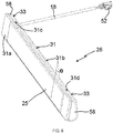
- the housing 31 comprises a front face 31a, a rear face 31b, a first lateral end 31c and a second lateral end 31d.
- the second lateral end 31d of the housing 31 is opposite to the first lateral end 31c of the housing 31.
- the autonomous electrical energy supply device 26 comprises two first supports 33.
- One of the first supports 33 is disposed at the first lateral end 31c of the housing 31.
- the other of the first supports 33 is disposed at the level of the second lateral end 31d of the housing 31.
- the autonomous electrical energy supply device 26 may comprise a single first support 33, disposed at one of the first and second lateral ends 31c, 31d of the housing 31.
- the photovoltaic panel 25 is assembled on the housing 31 and, more particularly, on the front face 31a of the housing 31, in an assembled configuration of the autonomous electrical energy supply device 26.
- the housing 31 and, more particularly, the front face 31a of the housing 31 comprises a recess 55 configured to receive the photovoltaic panel 25.
- the front face 31a of the housing 31 is inclined relative to the rear face 31b of the housing 31, in particular upwards, in an assembled configuration of the autonomous electrical energy supply device 26 with respect to the home automation installation.
- the front and rear faces 31a, 31b of the housing 31 approach each other by going upwards.
- the inclination of the photovoltaic panel 25 upward relative to the domotic installation for closing or solar protection makes it possible to improve the capture of the sunshine.
- the inclination of the photovoltaic panel 25 relative to the home automation system for closing or solar protection has an inclination value a, which can be included in a range of values strictly greater than 0 ° and less than or equal to 45 ° and, preferably, of the order of 15 °.
- the front face 31a of the housing 31 is parallel to the rear face 31b of the housing 31, in an assembled configuration of the autonomous electrical energy supply device 26 relative to the home automation installation, in other words the value of inclination ⁇ is equal to 0 °.
- first two supports 33 and, more particularly, to that which is arranged at the first lateral end 31c of the housing 31, in the assembled configuration of the supply device. in autonomous electrical energy 26.
- the first support 33 disposed at the second lateral end 31d of the housing 31, in the assembled configuration of the autonomous electrical energy supply device 26, serves only to guarantee the aesthetic appearance of the autonomous electrical energy supply device 26, being arranged in the extension of the housing 31.
- the housing 31 is assembled with the first supports 33, in particular with the first support 33 disposed at the first lateral end 31c of the housing 31, in the assembled configuration of the autonomous electrical energy supply device 26, and with the second support 34, in the assembled configuration of the autonomous electrical energy supply device 26.
- the photovoltaic panel 25 is fixed to the housing 31 by gluing.
- the method of fixing the photovoltaic panel to the housing is not limiting and may be different. It may, in particular, be a method of attachment by means of elastic snap fasteners.
- the first support 33 comprises at least one electrical connection device 36.
- the housing 31 comprises at least one first electrical connection device 40.
- the electrical connection devices 36, 40 are complementary plugs, in particular male and female, and intended to be plugged into one another.
- the assembly of the housing 31 with the first and second supports 33, 34 is implemented by a sliding movement F of the housing 31 relative to the first and second supports 33, 34, as illustrated by the Figures 4 and 5 .
- such an assembly by a sliding movement F of the housing 31 relative to the first and second supports 33, 34 makes it possible to guarantee simple, rapid and intuitive assembly and disassembly of the autonomous electrical energy supply device 26 and, more in particular, of the housing 31, of the photovoltaic panel 25 and of the electrical energy storage device 24 relative to the first and second supports 33, 34, so as to be able to replace the photovoltaic panel 25 or replace or recharge the battery 32 of the storage of electrical energy 24 or replace the unitary assembly formed by the housing 31, the photovoltaic panel 25 and the device for storage of electrical energy 24, without requiring the use of specific tools, without causing deterioration of the home automation installation and without having to dismantle the trunk 9 of the concealment device 3.
- first electrical connection device 40 of the housing 31 can be connected or disconnected from the electrical connection device 36 of the first support 33, in a simple manner, during the installation of the autonomous electrical energy supply device 26 relative to to the home automation installation or during a maintenance or repair intervention of the autonomous electrical energy supply device 26, in particular for the replacement of the photovoltaic panel 25 and the replacement or recharging of the battery 32 of the storage device electrical energy 24.
- the first electrical connection device 40 of the housing 31 can be disconnected and connected from the electrical connection device 36 of the first support 33, during a configuration operation of the motorized drive device 5 and, more particularly, of the electromechanical actuator 11, without having to dismantle the trunk 9 of the concealment device 3, without having to access the electrical connections connecting the electrical supply cable 18 to the electrical connection device 36 of the first support 33 and while maintaining the housing 31 in contact with the first and second supports 33, 34.
- Such a configuration operation of the motorized drive device 5 makes it possible to reinitialize at least part of the data memorized by the electronic control unit 15, following the simulation of a sequence of periods of power supply and power outage. in electrical energy from the electromechanical actuator 11, by connecting and disconnecting the first electrical connection device 40 of the housing 31 relative to the electrical connection device 36 of the first support 33.
- the electronic control unit 15 is configured to detect periods of supply and interruption of supply of electrical energy to the electromechanical actuator 11 from the autonomous electrical energy supply device 26 and, in particular, of the photovoltaic panel 25, only by means of measuring elements, not shown, of a quantity linked to the supply of electrical energy to the electromechanical actuator 11 by this photovoltaic panel 25.
- a period of supply of electrical energy to the electromechanical actuator 11 from the autonomous electrical energy supply device 26 corresponds to the presence of an electrical connection connecting the first electrical connection device 40 of the housing 31 with the electrical connection device 36 of the first support 33.
- a period of interruption of the electrical energy supply to the electromechanical actuator 11 from the autonomous electrical energy supply device 26 corresponds to the absence of electrical connection connecting the first electrical connection device 40 of the housing 31 with the device of electrical connection 36 of the first support 33.
- the quantity linked to the supply of electrical energy delivered by the photovoltaic panel 25 can be, in particular, a voltage, a current or an impedance.
- the measurement elements may include either a voltage divider, a comparator and a microcontroller, one of the inputs of which is provided with an analog-to-digital converter, in the case where the quantity measured is a voltage , or a shunt resistor and a microcontroller, one of the inputs of which is provided with an analog-to-digital converter, in the case where the quantity measured is a current.
- the data memorized by the electronic control unit 15 which can be reset can be, for example, the end positions of the screen 2, the obstacle detection threshold (s) and / or the control unit (s) 12, 13, 14 paired with the electromechanical actuator 11.
- the sliding movement F of the housing 31 relative to the first and second supports 33, 34 is implemented in a longitudinal direction of the housing 31. More particularly, the sliding movement F of the housing 31 relative to the first and second supports 33, 34 is implemented in a direction parallel to a face, in particular front, of the trunk 9 of the concealment device 3, to a face, in particular front, of one of the lateral slides 6 or to a wall d 'a building.
- the stroke of the sliding movement F of the housing 31 relative to the first and second supports 33, 34 is of the order of thirty-five millimeters.
- the length of the travel of the sliding movement of the housing relative to the first and second supports is not limiting and may be different.
- each of the first and second supports 33, 34 is configured to be fixed to a wall of an element 41, 6, 9 of the home automation installation by means of at least one fixing element, not shown.
- each of the first and second supports 33, 34 is fixed to the wall of the element 41, 6, 9 of the home automation installation by means of at least one fixing element, in the assembled configuration of the device. autonomous electrical energy supply 26 with respect to the home automation installation.
- each of the first and second supports 33, 34 comprises a single fixing element.
- the fixing element of each of the first and second supports 33, 34 on the wall of the element 41, 6, 9 of the home automation installation can be, for example, a fixing screw or a rivet.
- the number and type of fastening elements for each of the first and second supports on the wall of the element of the home automation installation are not limiting.
- the element 41, 6, 9 of the home automation installation is a wall 41 of a building, one of the side rails 6 of the concealment device 3 or the box 9 of the concealment device 3.
- the photovoltaic panel 25 can be replaced easily and the battery 32 can be replaced or recharged easily, during a maintenance or repair intervention of the autonomous electrical energy supply device 26.
- the unitary assembly formed by the autonomous electrical energy supply device 26 can thus be easily assembled on the wall of the element 41, 6, 9 of the home automation installation.
- first and second supports 33, 34 make it possible to guarantee an installation of the autonomous electrical energy supply device 26 in any type of domotic installation for closing or solar protection and in any configuration thereof, in particular on the wall 41 of a building, on one of the side rails 6 or on a wall of the trunk 9, more particularly on an outer face of a front wall of the trunk 9, as well as horizontally or vertically.
- each of the first and second supports 33, 34 can be fixed to this wall in the factory, then the housing 31 can be assembled on the first and second supports 33, 34 when the home automation installation is put into service.
- the assembly of the housing 31 and, consequently, of the photovoltaic panel 25 and of the electrical energy storage device 24 on the first and second supports 33, 34 during the commissioning of the home automation installation can thus make it possible to s free from problems encountered in waking up the communication module 27, during transport of the electromechanical actuator 11 comprising the electronic control unit 15, as well as problems of electrical energy consumption of the communication module 27 causing a discharge of the electrical energy storage device 24, since the autonomous electrical power supply device 6 is electrically disconnected from the electromechanical actuator 11 before the home automation installation is put into service.
- the autonomous electrical energy supply device 26 is disposed outside of the element 41, 6, 9 of the home automation installation, in the assembled configuration of the autonomous electrical energy supply device 26 relative to home automation installation.
- each of the first and second supports 33, 34 comprises at least one through hole 42, 43.
- each of the first and second supports 33, 34 comprises a single passage hole 42, 43.
- the through hole 42, 43 of each of the first and second supports 33, 34 cooperates, in other words is configured to cooperate, with the fixing element of this first or second support 33, 34 and with the wall of the element 41, 6, 9 of the home automation installation, in the assembled configuration of the autonomous electrical energy supply device 26 with respect to the home automation installation.
- the number of through holes of each of the first and second supports is not limiting and may be different. It can, in particular, be greater than or equal to two.
- the assembly of the housing 31 relative to the first and second supports 33, 34 is implemented following the fixing of each of the first and second supports 33, 34 on the wall of the element 41, 6, 9 of the home automation installation.
- the first support 33 is arranged in the extension of the housing 31, in particular of one of the first and second lateral ends 31c, 31d of the housing 31.
- the size of the autonomous electrical energy supply device 26 is limited.
- each of the first and second supports 33, 34 is made of a plastic material.
- the first support 33 also comprises a housing 48 inside which is arranged at least partially the electrical connection device 36, as illustrated in figures 8 and 11 .
- the housing 31 also comprises a housing 49 inside of which the first electrical connection device 40 is disposed at least in part, as illustrated in FIG. figure 8 .
- the first support 33 comprises a passage opening 46, as illustrated in the figure 7 .
- the passage opening 46 of the first support 33 cooperates, in other words is configured to cooperate, with the electrical supply cable 18, in the assembled configuration of the autonomous electrical energy supply device 26.
- the electrical connection device 36 of the first support 33 comprises at least one electrical connector 36a, 36b.
- the electrical connection device 36 of the first support 33 comprises two electrical connectors 36a, 36b, hereinafter called first electrical connector 36a and second electrical connector 36b.
- the number of electrical connectors of the electrical connection device of the first support is not limiting and may be different. It can, in particular, be one or greater than or equal to three.
- the first electrical connection device 40 of the housing 31 comprises at least one electrical connector 40a, 40b.
- the number of electrical connectors of the first connection device electrical enclosure is not limiting and may be different. It can, in particular, be one or greater than or equal to three.
- the first electrical connector 40a of the first electrical connection device 40 of the housing 31 cooperates, in other words is configured to cooperate, with the first electrical connector 36a of the electrical connection device 36 of the first support 33, in the assembled configuration of the device d autonomous electrical energy supply 26.
- the second electrical connector 40b of the first electrical connection device 40 of the housing 31 cooperates, in other words is configured to cooperate, with the second electrical connector 36b of the electrical connection device 36 of the first support 33, in the assembled configuration of the autonomous electrical energy supply device 26.
- the first electrical connection device 40 of the housing 31 is disposed at one of the first and second lateral ends 31c, 31d of the housing 31, in particular of the first lateral end 31c of the housing 31, as illustrated in figures 8 and 10 .
- the housing 31 includes at least one passage opening 44, 45 for the first electrical connection device 40 of the housing 31.
- the first electrical connection device 40 of the housing 31 is accessible from outside the housing 31 to electrically connect the latter to the electrical connection device 36 of the first support 33.
- the housing 31 includes a first passage opening 44 for the first electrical connector 40a of the first electrical connection device 40 of the housing 31.
- the housing 31 includes a second passage opening 45 for the second electrical connector 40b of the first electrical connection device 40 of the housing 31.
- first and second passage openings 44, 45 of the housing 31 are formed at one of the first and second lateral ends 31c, 31d of the housing 31 or at each of the first and second lateral ends 31c, 31d of the housing 31 .
- the first support 33 has a first version and a second version depending on the direction of mounting of the housing 31 with the first and second supports 33, 34, that is to say either at the first lateral end 31c of the box 31 is at the second lateral end 31d of the box 31.
- the mounting direction of the housing 31 with the first and second supports 33, 34 depends on the direction of the sliding movement F of the housing 31 relative to the first and second supports 33, 34, during assembly of the supply device for autonomous electrical energy 26.
- the first electrical connection device 40 of the housing 31 is disposed either at the first lateral end 31c of the housing 31 or at the second lateral end 31d of the housing 31, depending on the direction of mounting of the housing 31 with the first and second support 33, 34, that is to say either at the level of the first lateral end 31c of the housing 31 or at the level of the second lateral end 31d of the housing 31.
- the holding element 37 of the second support 34 cooperates, in other words is configured to cooperate, with the holding element 38 of the housing 31, in the assembled configuration of the autonomous electrical energy supply device 26.
- the interlocking element 39 of the housing 31 cooperates, in other words is configured to cooperate, with the interlocking element 35 of the first support 33, in the assembled configuration of the autonomous electrical energy supply device 26.
- first electrical connection device 40 of the housing 31 is assembled, in other words is configured to be assembled, with the electrical connection device 36 of the first support 33, in the assembled configuration of the autonomous electrical energy supply device 26 .
- the retaining element 38 of the housing 31 is disposed at the rear face 31b of the housing 31.
- the interlocking element 39 of the housing 31 is disposed at one of the first and second ends side 31c, 31d of the housing 31.
- the fitting element 35 of the first support 33 is a housing and the fitting element 39 of the housing 31 is a nozzle.
- the nesting element 39 of the housing 31 comprises at least one gadroon 67, so as to guarantee sealing between the housing 31 and the first support 33, in the assembled configuration of the autonomous electrical energy supply device 26 .
- the fitting element 39 of the housing 31 comprises two gadroons 67.
- the opening forming the holding element 38 of the housing 31 is oblong, so as to allow the sliding movement F of the housing 31 relative to the first and second supports 33, 34, during assembly of the device autonomous electric power supply 26.
- the oblong opening constituting the retaining element 38 of the housing 31 comprises an enlarged zone at one of its ends, so as to allow the insertion of the pin constituting the retaining element 37 of the second support 34 through said opening forming the holding element 38 of the housing 31.
- the holding element 38 of the housing 31 is formed in a recess 53 of the housing 31 and, more particularly, in the rear face 31b of the housing 31.
- the housing 31 includes two holding elements 38, that is to say two openings.
- Each of the holding elements 38 of the housing 31 is configured to cooperate with a holding element 37 of a second support 34, depending on the direction of mounting of the housing 31 with the first and second supports 33, 34.
- the nesting element 35 of the first support 33 is a nozzle and the nesting element 39 of the housing 31 is a housing.
- the holding element 37 of the second support 34 is an opening and the holding element 38 of the housing 31 is a pin.
- the housing 31 and, more particularly, the rear face 31b of the housing 31 comprises a housing 56 of the electrical energy storage device 24 and, more particularly, of the battery 32, as illustrated in FIG. figure 8 .
- the housing 31 and, more particularly, the rear face 31b of the housing 31 comprises holding elements 57 of the electrical energy storage device 24 and, more particularly, of the battery 32.
- the holding elements 57 of the electrical energy storage device 24 are ribs formed on an internal surface of the rear face 31b of the housing 31.
- the first support 33 is disposed at one of the first and second lateral ends 31c, 31d of the housing 31, in the assembled configuration of the autonomous electrical energy supply device 26.
- the second support 34 is disposed between the first lateral end 31c of the housing 31 and the second lateral end 31d of the housing 31, in the assembled configuration of the autonomous electrical energy supply device 26.
- the housing 31 of the autonomous electrical energy supply device 26 comprises two parts.
- the first part of the housing 31 corresponds to the front face 31a of the housing 31.
- the second part of the housing 31 corresponds to the rear face 31b of the housing 31.
- the first and second parts of the housing 31 are assembled together by means of fastening elements, not shown, in an assembled configuration of the housing 31.
- the fastening elements of the first part of the housing 31 with the second part of the housing 31 are fixing screws, four in number.
- Each of the fixing screws passes through a passage hole 54 formed in the second part 31b of the housing 31, as illustrated in figures 7 , 8 and 10 , and is screwed into a screwing barrel, not shown, formed in the first part 31a of the housing 31, in the assembled configuration of the housing 31.
- the type and number of fastening elements of the first and second parts of the housing are not limiting and may be different.
- the fastening elements can be, for example, elastic snap fastening elements and can be, for example, two or three in number.
- the housing 31 is made of plastic.
- the material of the housing is not limiting and may be different. It can be, in particular, aluminum.
- the autonomous electrical energy supply device 26 also comprises the electrical supply cable 18.
- the electrical supply cable 18 comprises at least two electrical supply wires 18a, 18b, as illustrated in FIG. figure 11 , hereinafter called first electrical supply wire 18a and second electrical supply wire 18b.
- the electrical connection device 36 of the first support 33 is electrically connected, in other words is configured to be electrically connected, with the first and second electrical supply wires 18a, 18b of the supply cable. electric 18, in the assembled configuration of the autonomous electric power supply device 26.
- the first support 33 can be fixed on the wall in the factory and then electrically connected to the power supply cable 18, itself electrically connected to the electromechanical actuator 11, so as to avoid reopening the boot 9 of the concealment device 3 during the setting in operation of the home automation system.
- the first electrical connector 36a of the electrical connection device 36 cooperates, in other words is configured to cooperate, with the first electrical supply wire 18a of the electrical supply cable 18, in the assembled configuration of the power supply device autonomous electrical 26.
- the second electrical connector 36b of the electrical connection device 36 cooperates, in other words is configured to cooperate, with the second electrical supply wire 18b of the electrical supply cable 18, in the assembled configuration of the device autonomous electric power supply 26.
- the electrical connection device 36 comprises a plate 59.
- the plate 59 is fixed, in other words configured to be fixed, on the body 58 of the first support 33, by means of fixing elements 60, in a configuration assembly of the first support 33.
- the fastening elements 60 of the plate 59 on the body 58 of the first support 33 are fixing screws, two in number.
- Each of the fixing screws passes through a through hole 61 formed in the plate 59 of the electrical connection device 36 and is screwed into a screwing barrel, not shown, formed inside the body 58 of the first support 33, in the configuration assembly of the first support 33.
- the type and number of fastening elements of the plate of the electrical connection device with the body of the first support are not limiting and may be different.
- the fastening elements can be, for example, elastic snap fastening elements and can be, for example, one or three or more.
- the plate 59 supports, in other words is configured to support, the first and second electrical connectors 36a, 36b of the electrical connection device 36.
- first and second electrical connectors 36a, 36b are integrated in the plate 59.
- the electrical supply cable 18 also comprises at at least one cooperating electrical connector 52, in other words being configured to cooperate, with at least one electrical connector, not shown, of the electromechanical actuator 11, in the assembled configuration of the autonomous electrical energy supply device 26 relative to the home automation installation.
- the autonomous electrical energy supply device 26 is electrically connected to the electromechanical actuator 11.
- the first support 33 also comprises a cable clamp 47.
- the cable clamp 47 cooperates, in other words is configured to cooperate, with the electric power cable 18, in the assembled configuration of the power supply device. autonomous electrical energy 26.
- the power supply cable 18 can be held in position relative to the first support 33 by means of the cable clamp 47, as well as relative to the wall of the element 41, 6, 9 of the home automation installation. , while allowing the disassembly of the housing 31, the photovoltaic panel 25 and the battery 32 with respect to the first and second supports 33, 34, in particular by means of fastening elements by insertion 35, 37, 38, 39.
- the photovoltaic panel 25 can be replaced easily and, optionally, the battery 32 can be replaced or recharged easily, during a maintenance or repair intervention of the autonomous electrical energy supply device 26.
- the disconnection of the first electrical connection device 40 from the housing 31 relative to the electrical connection device 36 of the first support 33 makes it possible to remove the housing 31, the photovoltaic panel 25 and the battery 32 relative to the first and second supports 33 , 34, while keeping the power supply cable 18 in position relative to the first support 33 by means of the cable clamp 47.
- the cable clamp 47 is disposed inside the housing 48 of the first support 33.
- the autonomous electrical energy supply device 26 also comprises a first interface element, not shown, and a second interface element, not shown.
- Each of the first and second interface elements cooperates, in other words is configured to cooperate, with one of the first and second supports 33, 34, in the assembled configuration of the autonomous electrical energy supply device 26 relative to the home automation installation.
- the first and second interface elements make it possible to guarantee the assembly of the autonomous electrical energy supply device 26 and, more particularly, of the housing 31 relative to the wall of the element 41, 6, 9 of the home automation installation, in particular in the case where the wall of the element 41, 6, 9 of the home automation installation is convex in shape, that is to say having a domed shape, in particular towards the outside of the building , or has imperfections or roughness.
- each of the first and second interface elements is fixed, in other words is configured to be fixed, to one of the first and second supports 33, 34 by means of at least one fixing element, in the assembled configuration of the autonomous electrical energy supply device 26 with respect to the home automation installation.
- the fixing element (s) of each of the first and second interface elements on one of the first and second supports 33, 34 can be, for example, fixing elements by elastic snap-fastening, in particular two in number.
- each fixing element is configured to cooperate and, more particularly, to engage in the through hole 42, 43 of one of the first and second supports 33, 34.
- the number and type of fastening elements of each of the first and second interface elements on one of the first and second supports are not limiting.
- each of the first and second interface elements comprises at least one passage opening, not shown, of at least one element fixing each of the first and second supports 33, 34 on the wall of the element 41, 6, 9 of the home automation installation.
- the autonomous electrical energy supply device 26 comprises at least one locking element 50 of the housing 31 relative to the first support 33.
- the autonomous electrical power supply device 26 comprises a single locking element 50.
- the locking element 50 is an elastic latching element.
- the locking element 50 is a sliding element configured to slide inside a groove 51 of the housing 31 between an unlocked position and a locked position.
- the locking element 50 is configured to bear against the first support 33 in the locked position.
- the locking of the housing 31 relative to the first support 33 can be implemented intuitively and without having to use a tool.
- the type and number of locking elements may be different. It may be, in particular, a screw, which may be captive, or a rivet.
- the autonomous electric power supply device 26 also comprises at least one other housing 31 'and at least one other photovoltaic panel 25', hereinafter called second housing and second photovoltaic panel.
- the second photovoltaic panel 25 ' is assembled, in other words configured to cooperate, with the second housing 31', in the assembled configuration of the autonomous electrical energy supply device 26.
- the autonomous electrical energy supply device 26 also comprises at least one other electrical energy storage device, not shown, hereinafter called the second electrical energy storage device.
- the second electrical energy storage device is arranged, in other words configured to be disposed, inside the second housing 31 ′, in the assembled configuration of the autonomous electrical energy supply device 26.
- the second housing 31 ' comprises a front face 31a', a rear face 31b ', a first lateral end 31c' and a second lateral end 31 d '.
- the second lateral end 31d 'of the housing 31' is opposite to the first lateral end 31c 'of the housing 31'.
- the housing 31 and the photovoltaic panel 25 described above, with reference to figures 4 to 10 are hereinafter called the first housing 31 and the first photovoltaic panel 25.
- the first housing 31 cooperates, in other words is configured to cooperate, with a single first support 33, disposed at the first lateral end 31c of the housing 31, in the assembled configuration of the autonomous electrical energy supply device 26.
- the second housing 31 ′ and second photovoltaic panel 25 ′ are identical to the first housing 31 and first photovoltaic panel 25.
- the second housing 31 ′ comprises at least one other first electrical connection device, not shown, identical to the first electrical connection device 40 of the first housing 31.
- the first electrical connection device 40 of each of the first and second boxes 31, 31 ' is arranged at the first lateral end 31c, 31c' of the first box 31 and the second box 31 '.
- the first housing 31 also includes a second electrical connection device, not shown.
- the second electrical connection device of the first housing 31 is similar to the first electrical connection device 40 of the first housing 31.
- the second electrical connection device of the first housing 31 is disposed at the second lateral end 31d of the first housing 31.
- the first support 33 includes the electrical connection device 36, as described above, with reference to figures 7 , 8 and 10 .
- first and second boxes 31, 31 ' are electrically connected by means of their second and first respective electrical connection devices and of the intermediate element 66.
- the electrical connection of at least two housings 31, 31 'and, therefore, of at least two photovoltaic panels 25, 25' in series and of at least one electrical energy storage device 24 allows to increase the electrical power supplied to the motorized drive device 5 and, more particularly, to the electromechanical actuator 11, by means of the electrical connection device 36 of the first support 33 and of the electrical supply cable 18.
- the assembly method prior to the step of assembling the housing 31 with the first and second supports 33, 34, the assembly method, in particular of the home automation installation, comprises a step of fixing each of the first and second supports 33 , 34 on the wall of element 41, 6, 9 of the home automation system by means of at least one fixing element.
Landscapes
- Charge And Discharge Circuits For Batteries Or The Like (AREA)
- Electric Propulsion And Braking For Vehicles (AREA)
Applications Claiming Priority (1)
| Application Number | Priority Date | Filing Date | Title |
|---|---|---|---|
| FR1855885A FR3083404B1 (fr) | 2018-06-28 | 2018-06-28 | Dispositif d'alimentation en energie electrique autonome, dispositif d'entrainement motorise et installation domotique associes |
Publications (1)
| Publication Number | Publication Date |
|---|---|
| EP3588772A1 true EP3588772A1 (de) | 2020-01-01 |
Family
ID=63579406
Family Applications (1)
| Application Number | Title | Priority Date | Filing Date |
|---|---|---|---|
| EP19182802.9A Pending EP3588772A1 (de) | 2018-06-28 | 2019-06-27 | Autonome stromzuführungsvorrichtung, entsprechende motorisierte antriebsvorrichtung und entsprechende haustechnikanlage |
Country Status (2)
| Country | Link |
|---|---|
| EP (1) | EP3588772A1 (de) |
| FR (1) | FR3083404B1 (de) |
Cited By (3)
| Publication number | Priority date | Publication date | Assignee | Title |
|---|---|---|---|---|
| EP4283864A1 (de) * | 2022-05-25 | 2023-11-29 | Delta Dore | Photovoltaiktafelsystem mit verformbaren befestigungsmitteln |
| EP4407134A1 (de) * | 2023-01-30 | 2024-07-31 | VKR Holding A/S | Gebäudeöffnungsabdeckungssystem mit einem antriebssystem mit einer aufweckeinheit zur bereitstellung eines aufweckbefehls und verfahren zum bereitstellen einer automatischen ersten aktivierung einer funkkommunikationssteueranordnung eines antriebssystems |
| EP4576463A1 (de) | 2023-12-20 | 2025-06-25 | Somfy Activites SA | Stromversorgungsvorrichtung, motorisierte antriebsvorrichtung mit solch einer stromversorgungsvorrichtung und verdunkelungsvorrichtung dafür |
Citations (5)
| Publication number | Priority date | Publication date | Assignee | Title |
|---|---|---|---|---|
| EP1703063A1 (de) | 2005-02-16 | 2006-09-20 | IFN-Holding AG | Fensterprofil mit Solar-Element |
| WO2011138556A2 (fr) * | 2010-05-06 | 2011-11-10 | Bubendorff | Procédé de contrôle de l'alimentation en énergie électrique d'une batterie d'un dispositif d'occultation par un panneau photovoltaïque et dispositif d'occultation comportant un système pour un tel contrôle |
| CN202307926U (zh) | 2011-10-18 | 2012-07-04 | 宁波杜亚机电技术有限公司 | 一种太阳能面板的穿线结构 |
| FR3016001A1 (fr) * | 2013-12-31 | 2015-07-03 | Somfy Sas | Fenetre pour batiment |
| CN207377458U (zh) * | 2017-10-25 | 2018-05-18 | 北京伟业窗饰遮阳帘有限公司 | 一种太阳能传感遮阳帘 |
-
2018
- 2018-06-28 FR FR1855885A patent/FR3083404B1/fr active Active
-
2019
- 2019-06-27 EP EP19182802.9A patent/EP3588772A1/de active Pending
Patent Citations (5)
| Publication number | Priority date | Publication date | Assignee | Title |
|---|---|---|---|---|
| EP1703063A1 (de) | 2005-02-16 | 2006-09-20 | IFN-Holding AG | Fensterprofil mit Solar-Element |
| WO2011138556A2 (fr) * | 2010-05-06 | 2011-11-10 | Bubendorff | Procédé de contrôle de l'alimentation en énergie électrique d'une batterie d'un dispositif d'occultation par un panneau photovoltaïque et dispositif d'occultation comportant un système pour un tel contrôle |
| CN202307926U (zh) | 2011-10-18 | 2012-07-04 | 宁波杜亚机电技术有限公司 | 一种太阳能面板的穿线结构 |
| FR3016001A1 (fr) * | 2013-12-31 | 2015-07-03 | Somfy Sas | Fenetre pour batiment |
| CN207377458U (zh) * | 2017-10-25 | 2018-05-18 | 北京伟业窗饰遮阳帘有限公司 | 一种太阳能传感遮阳帘 |
Cited By (6)
| Publication number | Priority date | Publication date | Assignee | Title |
|---|---|---|---|---|
| EP4283864A1 (de) * | 2022-05-25 | 2023-11-29 | Delta Dore | Photovoltaiktafelsystem mit verformbaren befestigungsmitteln |
| FR3136133A1 (fr) * | 2022-05-25 | 2023-12-01 | Delta Dore | Système de panneau photovoltaïque comportant des moyens de fixation déformables |
| EP4407134A1 (de) * | 2023-01-30 | 2024-07-31 | VKR Holding A/S | Gebäudeöffnungsabdeckungssystem mit einem antriebssystem mit einer aufweckeinheit zur bereitstellung eines aufweckbefehls und verfahren zum bereitstellen einer automatischen ersten aktivierung einer funkkommunikationssteueranordnung eines antriebssystems |
| WO2024160561A1 (en) * | 2023-01-30 | 2024-08-08 | Vkr Holding A/S | A drive system comprising a wake-up unit configured to provide a wake-up command |
| EP4576463A1 (de) | 2023-12-20 | 2025-06-25 | Somfy Activites SA | Stromversorgungsvorrichtung, motorisierte antriebsvorrichtung mit solch einer stromversorgungsvorrichtung und verdunkelungsvorrichtung dafür |
| FR3157703A1 (fr) | 2023-12-20 | 2025-06-27 | Somfy Activites Sa | Dispositif d’alimentation en énergie électrique, dispositif d’entraînement motorisé comprenant un tel dispositif d’alimentation en énergie électrique, et dispositif d’occultation associé |
Also Published As
| Publication number | Publication date |
|---|---|
| FR3083404A1 (fr) | 2020-01-03 |
| FR3083404B1 (fr) | 2020-09-25 |
Similar Documents
| Publication | Publication Date | Title |
|---|---|---|
| EP3803021B1 (de) | Rollladenvorrichtung für eine heimautomatisierungs- oder sonnenschutzvorrichtung in einem gebäude und zugehörige heimautomatisierungsinstallation | |
| EP3283721B1 (de) | Motorisierte antriebsvorrichtung für eine schliess- oder sonnenschutz-heimautomatisierungsanlage, zugehörige heimautomatisierungsanlage und verfahren zur steuerung des betriebs solch einer vorrichtung | |
| FR3072116B1 (fr) | Actionneur electromecanique tubulaire et installation domotique comprenant un tel actionneur | |
| EP3528310B1 (de) | Speichervorrichtung für elektrische energie, entsprechende motorisierte antriebsvorrichtung und entsprechende haustechnikanlage | |
| EP3504393B1 (de) | Motorisierte antriebsvorrichtung für eine schliess- oder sonnenschutzeinheit und entsprechende einheit | |
| FR3072118B1 (fr) | Actionneur electromecanique tubulaire et installation domotique comprenant un tel actionneur | |
| EP3695086B1 (de) | Rohrmotor, heimautomatisierung mit diesem motor und sein herstellungsverfahren | |
| EP3695087B1 (de) | Rohrförmiger elektromechanischer aktuator, heimautomatisierungsausrüstung mit solch einem aktuator und verfahren zur verbindung solch eines aktuators | |
| EP3588772A1 (de) | Autonome stromzuführungsvorrichtung, entsprechende motorisierte antriebsvorrichtung und entsprechende haustechnikanlage | |
| FR3072119B1 (fr) | Actionneur electromecanique tubulaire et installation domotique comprenant un tel actionneur | |
| FR3100266A1 (fr) | Dispositif d’alimentation en énergie électrique autonome, dispositif d’entraînement motorisé, installation et fenêtre associés | |
| FR3093124A1 (fr) | Agencement de moyens de stockage d'energie electrique dans une motorisation de volet roulant et le volet roulant l'incluant | |
| EP2937505B1 (de) | Heimanlage, die eine befestigungsvorrichtung für einen motorisierten antriebsmechanismus eines aufrollrohrs eines bildschirms in einem kasten umfasst | |
| EP4576463A1 (de) | Stromversorgungsvorrichtung, motorisierte antriebsvorrichtung mit solch einer stromversorgungsvorrichtung und verdunkelungsvorrichtung dafür | |
| EP4175119B1 (de) | Motorisierte antriebsvorrichtung, verdunkelungsvorrichtung und steuerungsverfahren dafür | |
| EP4086423B1 (de) | Motorisierte antriebsvorrichtung für eine verdunkelungsvorrichtung und entsprechende verdunkelungsvorrichtung | |
| EP4704313A1 (de) | Elektromechanischer aktuator und verdunkelungsvorrichtung mit solch einem elektromechanischen aktuator | |
| EP4442953A1 (de) | Verdunkelungsvorrichtung | |
| EP4442954A1 (de) | Verdunkelungsvorrichtung | |
| EP4704501A1 (de) | Stromversorgungsvorrichtung, motorantriebsvorrichtung mit einer solchen stromversorgungsvorrichtung und verdunkelungsvorrichtung dafür | |
| WO2022207133A1 (fr) | Actionneur électromécanique et installation de fermeture, d'occultation ou de protection solaire comprenant un tel actionneur électromécanique | |
| FR3139592A1 (fr) | Dispositif d’entraînement motorisé d’un dispositif d’occultation et dispositif d’occultation associé |
Legal Events
| Date | Code | Title | Description |
|---|---|---|---|
| PUAI | Public reference made under article 153(3) epc to a published international application that has entered the european phase |
Free format text: ORIGINAL CODE: 0009012 |
|
| STAA | Information on the status of an ep patent application or granted ep patent |
Free format text: STATUS: THE APPLICATION HAS BEEN PUBLISHED |
|
| AK | Designated contracting states |
Kind code of ref document: A1 Designated state(s): AL AT BE BG CH CY CZ DE DK EE ES FI FR GB GR HR HU IE IS IT LI LT LU LV MC MK MT NL NO PL PT RO RS SE SI SK SM TR |
|
| AX | Request for extension of the european patent |
Extension state: BA ME |
|
| STAA | Information on the status of an ep patent application or granted ep patent |
Free format text: STATUS: REQUEST FOR EXAMINATION WAS MADE |
|
| 17P | Request for examination filed |
Effective date: 20200609 |
|
| RBV | Designated contracting states (corrected) |
Designated state(s): AL AT BE BG CH CY CZ DE DK EE ES FI FR GB GR HR HU IE IS IT LI LT LU LV MC MK MT NL NO PL PT RO RS SE SI SK SM TR |
|
| RAP1 | Party data changed (applicant data changed or rights of an application transferred) |
Owner name: SIMU |
|
| STAA | Information on the status of an ep patent application or granted ep patent |
Free format text: STATUS: EXAMINATION IS IN PROGRESS |
|
| 17Q | First examination report despatched |
Effective date: 20211012 |