EP3590740A1 - Hydraulic arrangement for hydraulic suspensions of a work vehicle - Google Patents
Hydraulic arrangement for hydraulic suspensions of a work vehicle Download PDFInfo
- Publication number
- EP3590740A1 EP3590740A1 EP19183536.2A EP19183536A EP3590740A1 EP 3590740 A1 EP3590740 A1 EP 3590740A1 EP 19183536 A EP19183536 A EP 19183536A EP 3590740 A1 EP3590740 A1 EP 3590740A1
- Authority
- EP
- European Patent Office
- Prior art keywords
- valve
- piston
- orifice
- work vehicle
- connection module
- Prior art date
- Legal status (The legal status is an assumption and is not a legal conclusion. Google has not performed a legal analysis and makes no representation as to the accuracy of the status listed.)
- Withdrawn
Links
- 239000000725 suspension Substances 0.000 title claims abstract description 23
- 239000012530 fluid Substances 0.000 claims abstract description 43
- 238000011144 upstream manufacturing Methods 0.000 claims description 7
- 230000033001 locomotion Effects 0.000 description 7
- 238000006467 substitution reaction Methods 0.000 description 4
- 230000001276 controlling effect Effects 0.000 description 3
- 230000001105 regulatory effect Effects 0.000 description 3
- 238000012986 modification Methods 0.000 description 2
- 230000004048 modification Effects 0.000 description 2
- 230000005540 biological transmission Effects 0.000 description 1
- 238000013016 damping Methods 0.000 description 1
- 238000007689 inspection Methods 0.000 description 1
- 238000005096 rolling process Methods 0.000 description 1
Images



Classifications
-
- B—PERFORMING OPERATIONS; TRANSPORTING
- B60—VEHICLES IN GENERAL
- B60G—VEHICLE SUSPENSION ARRANGEMENTS
- B60G11/00—Resilient suspensions characterised by arrangement, location or kind of springs
- B60G11/26—Resilient suspensions characterised by arrangement, location or kind of springs having fluid springs only, e.g. hydropneumatic springs
- B60G11/265—Resilient suspensions characterised by arrangement, location or kind of springs having fluid springs only, e.g. hydropneumatic springs hydraulic springs
-
- B—PERFORMING OPERATIONS; TRANSPORTING
- B60—VEHICLES IN GENERAL
- B60G—VEHICLE SUSPENSION ARRANGEMENTS
- B60G17/00—Resilient suspensions having means for adjusting the spring or vibration-damper characteristics, for regulating the distance between a supporting surface and a sprung part of vehicle or for locking suspension during use to meet varying vehicular or surface conditions, e.g. due to speed or load
- B60G17/02—Spring characteristics, e.g. mechanical springs and mechanical adjusting means
- B60G17/04—Spring characteristics, e.g. mechanical springs and mechanical adjusting means fluid spring characteristics
- B60G17/056—Regulating distributors or valves for hydropneumatic systems
-
- B—PERFORMING OPERATIONS; TRANSPORTING
- B60—VEHICLES IN GENERAL
- B60G—VEHICLE SUSPENSION ARRANGEMENTS
- B60G21/00—Interconnection systems for two or more resiliently-suspended wheels, e.g. for stabilising a vehicle body with respect to acceleration, deceleration or centrifugal forces
- B60G21/02—Interconnection systems for two or more resiliently-suspended wheels, e.g. for stabilising a vehicle body with respect to acceleration, deceleration or centrifugal forces permanently interconnected
- B60G21/06—Interconnection systems for two or more resiliently-suspended wheels, e.g. for stabilising a vehicle body with respect to acceleration, deceleration or centrifugal forces permanently interconnected fluid
- B60G21/073—Interconnection systems for two or more resiliently-suspended wheels, e.g. for stabilising a vehicle body with respect to acceleration, deceleration or centrifugal forces permanently interconnected fluid between wheels on the same axle but on different sides of the vehicle, i.e. the left and right wheel suspensions being interconnected
-
- B—PERFORMING OPERATIONS; TRANSPORTING
- B60—VEHICLES IN GENERAL
- B60G—VEHICLE SUSPENSION ARRANGEMENTS
- B60G2202/00—Indexing codes relating to the type of spring, damper or actuator
- B60G2202/10—Type of spring
- B60G2202/15—Fluid spring
-
- B—PERFORMING OPERATIONS; TRANSPORTING
- B60—VEHICLES IN GENERAL
- B60G—VEHICLE SUSPENSION ARRANGEMENTS
- B60G2204/00—Indexing codes related to suspensions per se or to auxiliary parts
- B60G2204/80—Interactive suspensions; arrangement affecting more than one suspension unit
- B60G2204/82—Interactive suspensions; arrangement affecting more than one suspension unit left and right unit on same axle
-
- B—PERFORMING OPERATIONS; TRANSPORTING
- B60—VEHICLES IN GENERAL
- B60G—VEHICLE SUSPENSION ARRANGEMENTS
- B60G2204/00—Indexing codes related to suspensions per se or to auxiliary parts
- B60G2204/80—Interactive suspensions; arrangement affecting more than one suspension unit
- B60G2204/83—Type of interconnection
- B60G2204/8304—Type of interconnection using a fluid
Definitions
- the present invention concerns a hydraulic arrangement for a work vehicle, in particular hydraulic arrangement for controlling hydraulic suspensions of a work vehicle.
- Vehicles usually comprise suspensions which connect the axle to the chassis of this latter and configured to dampen a movement of the axle with respect to chassis so as to avoid the transmission of road irregularities to chassis and, thus, to driver's cab. Indeed, the aforementioned movements, in particular rolling of the vehicle, are particular annoying for the driver of the vehicle.
- Such hydraulic arrangement 100 comprises a first cylinder 101, e.g. a right cylinder of a right suspension for an axle of a vehicle and a second cylinder 102, e.g. a left cylinder of a left suspension for said axle of the vehicle.
- Each cylinder 101, 102 comprises a piston chamber 101p, 102p and a rod chamber 101r, 102r each connected together to a source of fluid in pressure and to drain as disclosed in greater detail in the following.
- rod chambers 101r, 102r are fluidly connected together via a first connection line 105 to a first source 103 of fluid in pressure; first connection line 105 is moreover fluidly connected to a levelling valve 106 for lowering and raising the suspension .
- Piston chambers 101p, 102p are fluidly connected together via a second connection line 107 to a second source 104 of fluid in pressure; second connection line 107 is moreover fluidly connected to the levelling valve 106.
- Selection stage 110 comprises a selection valve 111 configured to selectively allow the passage of the fluid from second source 104 of fluid to piston chambers 101p, 102p; in the disclosed scheme valve 111 is an electrically actuated two way two positions valve.
- Selection stage 110 further comprises an orifice 112 fluidly interposed in parallel to , i.e. bypassing, selection valve 111.
- selection valve 111 is arranged so that forces the passage of fluid from second source 104 to flow to piston chambers 101p, 102p via orifice 112.
- selection valve 111 is arranged so that fluid from second source 104 to piston flows to chambers 101p, 102p directly through valve 111.
- first working mode suspensions are not active, i.e. valve 111 is positioned so as to force passage of fluid from sources 104 to chambers 101p, 102p via orifice 112, while in second working mode suspensions are active, i.e. valve 111 is positioned so as to allow free passage of fluid from sources 104 to chambers 101p, 102p. Accordingly, in first working mode suspensions are soft, allowing a vertical movement of the axle connected to the suspensions, while in second working mode they are locked, locking consequently a vertical movement of such axle.
- piston chambers 101p, 102p are fluidly directly connected to each other. Indeed, fluid coming from a piston chamber 101p, 102p flows directly to the other piston chamber 101p, 102p through orifice 112 which is only configured to balance pressures of fluid upstream and downstream with respect to valve 111.
- An aim of the present invention is to satisfy the above mentioned needs in an optimized and cost-effective way.
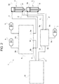
- Figure 2 discloses a hydraulic arrangement 1 according to the present invention comprising a first cylinder 2, e.g. a right cylinder of a right suspension for an axle of a work vehicle and a second cylinder 3, e.g. a left cylinder of a left suspension of said axle the work vehicle.
- Each cylinder 2, 3 comprises a piston chamber 2p, 3p and a rod chamber 2r, 3r each connected as disclosed in greater detail in the following.
- Piston chambers 2p, 3p are fluidly connected via respective piston connection lines 4, 4' to respective first sources 5 of fluid in pressure, namely a weight loaded or a spring loaded accumulator, a gas charged piston or a bladder, while rod chambers 2r, 3r are fluidly connected via respective rod connection lines 6, 6' to a source 7 of fluid in pressure.
- Hydraulic arrangement 1 further comprises a piston connection module 8 and a rod connection module 9 respectively fluidly interposed between sources 5 and piston chambers 2p, 3p on piston connection lines 4, 4' and between source 7 and rod chambers 2r, 3r on rod connection lines 6, 6' .
- Such piston and rod connection module are further fluidly connected to a levelling valve 10 via respective connection conduits 11, 11'.
- piston connection module 8 comprises first and second openings 8a, 8b fluidly connected via piston connection lines 4, 4' to piston chambers 2p, 3p, a third opening 8c fluidly connected via connection conduit 11 to levelling valve 10 and fourth and fifth openings 8d, 8e fluidly connected to sources 5.
- Rod connection module 9 comprises first and second openings 9a, 9b fluidly connected via piston connection lines 6, 6' to rod chambers 2r, 3r, a third opening 9d fluidly connected via connection conduit 11' to levelling valve 10 and fourth openings 9c fluidly connected to source 7, of any of the aforementioned typology.
- piston connection module 8 is configured to regulate the fluid communication between the first source 5 and piston chambers 2p, 3p from a first level in which there is no fluidic communication and a second level in which there is fully fluidic communication. Such regulation is achieved by valves as described in the following in greater detail.
- piston connection module 8 is configured to allow the control of roll of the vehicle in all working modes of the suspensions, i.e. during all regulations of the fluid between first source 5 and piston chambers 2p, 3p.
- rod connection module 9 comprises a conduit 12 directly fluidly connecting openings 9a, 9b and 9c, 9d together while piston connection module 8 comprises the elements as described hereunder.
- Piston connection module 8 comprises a couple of valves 14, 14', for sake of clarity a left and a right valve, preferably proportional electro-actuated valves, respectively fluidly interposed between openings 8b and 8e and 8a and 8d of module 8 on piston connection lines 4, 4'.
- Connection conduit 11 is fluidly connected through opening 8c to a pair of split conduits 15, 15' which are connected respectively to piston connection lines 4, 4' downstream with respect to left and right valves 14, 14'.
- Left split conduit 15 comprises a first orifice 16 and right split conduit 15' comprises a second orifice 17. Said orifices are used to restricts the flow path in which they are placed.
- the orifices 16, 17 and 18 preferably are passive orifices or a passive orifice proportional valve or single proportional valves or variable orifices or any combination thereof.
- piston connection module 8 further comprises a third orifice 18 fluidly interposed on a duct 19 fluidly connecting valves 14, 14' upstream these latter but downstream openings 8d, 8e.
- third orifice 18 has a size that is wider than the sizes of the first and second orifices 16, 17; more preferably the size of the third orifice is comprised between 1 and 5 mm and the sizes of the first and second orifices are both comprised between 0,5 and 2,5 mm.
- first and second orifices 16, 17 may have a different size each other.
- Piston connection module may further comprise a drain valve 20, fluidly bypassing one of valves 14, 14', preferably right valve 14', configured to drain oil from circuit 1 for inspection of valves 14, 14'.
- Piston connection module 8 may further comprise a pair of non-return valves 21, 21' respectively bypassing the orifices 16 and 17; non-return valves 21, 21' preferably allow the passage of fluid from pistons 2 and 3 to opening 8c but not the opposite.
- valves 14, 14' are positioned so that fluid cannot flow directly from sources 5 to piston chambers 2p, 3p.
- piston chambers may fluidly communicate thanks to orifices 16, 17 which allows a, strict, passage of fluid if one of the two cylinders varies its working position. If, supposing, right cylinder 2 would compress piston chamber 2p, e.g. because of ground conformation during passage of the work vehicle, fluid will be pushed towards piston chamber 3p of left cylinder 3 via orifice 16.
- valves 14, 14' are positioned so that fluid may flow directly from sources 5 to piston chambers 2p, 3p.
- piston chambers may fluidly communicate thanks to orifice 18 which allows a, passage of fluid if one of the two cylinders varies its working position. If, supposing, right cylinder 2 would compress piston chamber 2p, e.g. because of ground conformation during passage of the work vehicle, fluid will be pushed towards piston chamber 3p of left cylinder 3 via orifice 18. Since the orifices 18 reduces the oil flow, it consequently dampens the axle tilting in this second working mode. Similarly to the first working mode, fluid may through one of valves 21, 21' to levelling valve 10. Moreover fluid would not pass through orifices 16 and 17 because their sizes are smaller compared to the size of orifice 18 which then offers less resistance to fluid passage.
- piston connection module 8 may be realized as follows.
- FIG 4a discloses the same structure of the preferred described embodiment, but, in substitution of valves 14, 14' any of the two ways-two positions valves 9a to 9f may be used, i.e. a ON-OFF valve as shown in figures 9b and 9e , a proportional valve as shown in figures 9a and 9f or a bi-flow valve as shown in figures 9c (proportional) or 9b (ON/OFF) .
- FIG 4b discloses the same structure of the preferred described embodiment, however non-return valves 21, 21' are absent and, in substitution of valves 14, 14', any of the above mentioned two ways-two positions valves 9a to 9f may be used.
- Figure 4c discloses the same structure of the preferred described embodiment, however non-return valves 21, 21' are absent and, in substitution of valves 14, 14', any of the above mentioned two ways-two positions valves 9a to 9f may be used. Moreover, only second orifice 17 is present while no orifice are present on left split conduit 15.
- Figure 4d discloses the same structure of the preferred described embodiment, however non-return valves are substituted by a shuttle valve 22 interposed between split conduits 15, 15' and, in substitution of valves 14, 14', any of the above mentioned two ways-two positions valves 9a to 9f may be used. Moreover, only second orifice 17 is present, fluidly interposed in parallel upstream to shuttle valve 22 downstream with respect to valves 14, 14'.
- Figures 5a to 5d or figures 6a to 6d disclose embodiments of piston connection module 8 which comprises a single valve, namely a four-ways valve instead of two-ways valve.
- Figure 5a discloses the same structure of the preferred described embodiment, however only a single four ways valve 14 is present fluidly interposed between first and second orifices 16, 17.
- Such four ways valve 14 may be, for instance a proportional four ways - three positions valve as disclosed in figure 9g , a ON-OFF four ways - three positions valve as disclosed in figure 9h , a ON-OFF four way - two position valve as disclosed in figure 9i or an externally controlled proportional four ways - two positions valve as disclosed in figure 9l .
- Figure 5b discloses an embodiment in which non-return valves 21 of the preferred embodiment are substituted by a shuttle valve 22 interposed between split conduits 15, 15'; moreover, only second orifice 17 is present, fluidly interposed in parallel upstream to shuttle valve 22 and downstream with respect to the single valve 14.
- Single valve 14 may be of any of the above cited four ways - three positions valves a 9g or 9h and is fluidly interposed between second orifice 17 and fourth and fifth openings 8d, 8e.
- Figure 5c discloses an embodiment similar to the embodiment of figure 5b in which no check valves 22 are present and only second orifice 17 is present while no orifice are present on left split conduit 15.
- Figure 5d discloses an embodiment similar to the embodiment of figure 5c in which first orifice 16 is present on left split conduit and second orifice 17 is present on right split conduit 15.
- Figure 6a discloses an embodiment similar to the embodiment of figure 5b but further comprising a second orifice 18 fluidly interposed in parallel to valve 14 upstream to this latter.
- Single valve 14 may be a four ways - two positions valve, e.g. a ON-OFF two position-four ways valve as disclosed in figure 9i or an externally controlled ON-OFF four ways - two positions valve as disclosed in figure 9l .
- Figure 6b discloses an embodiment similar to the embodiment of figure 6a in which no check valves 22 are present and only second orifice 17 is present while no orifice are present on left split conduit 15.
- Figure 6c discloses an embodiment similar to the embodiment of figure 6b in which first orifice 16 is present on left split conduit and second orifice 17 is present on right split conduit 15.
- Figures 7a and 7b disclose embodiments of piston connection module 8 which comprises a three valves, for instance as described in the following.
- Figure 7a discloses an embodiment in which fourth and fifth openings 8d, 8e are fluidly connected to first and second openings 8a, 8b and comprises valves 14, 14' each fluidly interposed respectively between fifth and first openings 8a, 8e and 8b, 8d.
- Third opening 8c is fluidly connected via split conduits 15, 15' to valves 14, 14' downstream these latter.
- Module 8 further comprises a third valve 14" fluidly interposed on one of split conduits 15, 15', preferably the right one.
- Valves 14, 14' may be a two ways - two positions valve, and in particular any of valves 9a to 9f may be used, i.e.
- valve 14 may be any of valves 9a or 9m (external ON/OFF pilot valve).
- Figure 7B discloses an embodiment similar to the embodiment of figure 7a in which a shuttle valve 22 is present fluidly interposed between third opening 8c and split conduits 15, 15' and a third valve 14" is fluidly interposed in parallel upstream with respect to shuttle valve 22 but downstream with respect to valves 14, 14'.
- Valves 14, 14', 14" may be any of the ones cited for the circuit of figure 7a .
- valve 14" is functional equivalent, being a proportional valve, of the orifices 16, 17 and 18 of the described preferred embodiments.
- rod connection module 9 For each of the above described embodiments of piston connection module 8, a different rod connection module 9 may be realized as follows.
- Figure 8a discloses the rod connection module 9 according to the preferred embodiment of the present invention.
- Figure 8b discloses an embodiment similar to the embodiment of figure 8a in which a valve 14''' is fluidly interposed between source 7 and lines 11', 6, 6' .
- Valve 14''' may be any of the two way- two positions valves 9a to 9f as disclosed above.
- Figure 8c discloses an embodiment similar to the embodiment of figure 8a in which two further fourth orifices 23, 23' are respectively fluidly interposed on conduits 6, 6' .
- Figures 8d and 8e disclose respective embodiments similar to the embodiment of figure b in which two further fourth orifices 23, 23' are respectively fluidly interposed on conduits 6, 6' ( figure 8d ) or a single further fourth orifice 23 is fluidly interposed on one between conduits 6, 6', preferably conduit 6'.
- orifice 18 Since additional the size of orifice 18 is wider than the sizes of the first and second orifices 16, 17 the suspension will be controlled in a softer way than in the opposite working mode in which suspension will be stiffer because of the different dimensions of the above mentioned sizes of the orifices.
- Such stiffness may be regulated by regulating the dimension of orifices 16, 17 and 18 and/or pressure or flow of fluid coming from sources 5 and 7.
- orifices 16 and 17 are different between each other, they compensate different pressure drop along the lines going from piston module to the piston chambers.
- variable roll damping may be regulated.
- drain valve 20 may be absent or positioned in any other useful location in the arrangement 1.
Landscapes
- Engineering & Computer Science (AREA)
- Mechanical Engineering (AREA)
- Vehicle Body Suspensions (AREA)
Abstract
Description
- The present invention concerns a hydraulic arrangement for a work vehicle, in particular hydraulic arrangement for controlling hydraulic suspensions of a work vehicle.
- Vehicles usually comprise suspensions which connect the axle to the chassis of this latter and configured to dampen a movement of the axle with respect to chassis so as to avoid the transmission of road irregularities to chassis and, thus, to driver's cab. Indeed, the aforementioned movements, in particular rolling of the vehicle, are particular annoying for the driver of the vehicle.
- To solve the aforementioned problem it is known to provide, between right and left suspension of a suspension system, a hydraulic arrangement as disclosed in
Figure 1 . - Such
hydraulic arrangement 100, as known in the prior art, comprises afirst cylinder 101, e.g. a right cylinder of a right suspension for an axle of a vehicle and asecond cylinder 102, e.g. a left cylinder of a left suspension for said axle of the vehicle. Eachcylinder piston chamber rod chamber - In particular,
rod chambers first connection line 105 to afirst source 103 of fluid in pressure;first connection line 105 is moreover fluidly connected to alevelling valve 106 for lowering and raising the suspension . Pistonchambers second connection line 107 to asecond source 104 of fluid in pressure;second connection line 107 is moreover fluidly connected to thelevelling valve 106. - Between
second source 104 of fluid in pressure andpiston chambers selection stage 110 is fluidly interposed.Selection stage 110 comprises aselection valve 111 configured to selectively allow the passage of the fluid fromsecond source 104 of fluid topiston chambers scheme valve 111 is an electrically actuated two way two positions valve. -
Selection stage 110 further comprises anorifice 112 fluidly interposed in parallel to , i.e. bypassing,selection valve 111. - The above described
hydraulic arrangement 100 as known in the prior art can provide two working modes. According to a first working mode (as shown infigure 1 ),selection valve 111 is arranged so that forces the passage of fluid fromsecond source 104 to flow topiston chambers orifice 112. According to a second working mode (not shown),selection valve 111 is arranged so that fluid fromsecond source 104 to piston flows tochambers valve 111. - In first working mode suspensions are not active,
i.e. valve 111 is positioned so as to force passage of fluid fromsources 104 tochambers orifice 112, while in second working mode suspensions are active,i.e. valve 111 is positioned so as to allow free passage of fluid fromsources 104 tochambers - According to the described arrangement, roll cannot be controlled in both situations because
piston chambers piston chamber other piston chamber orifice 112 which is only configured to balance pressures of fluid upstream and downstream with respect tovalve 111. - In view of the preceding, the need is felt to provide a hydraulic arrangement for controlling roll of a work machine which allows roll control during all operative conditions of the circuit.
- An aim of the present invention is to satisfy the above mentioned needs in an optimized and cost-effective way.
- The aforementioned aim is reached by a hydraulic arrangement for hydraulic suspensions for a work vehicle as claimed in the appended set of claims.
- For a better understanding of the present invention, a preferred embodiment is described in the following, by way of a non-limiting example, with reference to the attached drawings wherein:
-
Figure 1 is a scheme of a hydraulic arrangement for hydraulic suspensions for work vehicle as known in the art; -
Figure 2 is a scheme of a hydraulic arrangement for hydraulic suspensions for work vehicle according to the present invention; -
Figure 3 is a scheme of an exemplary embodiment of hydraulic arrangement for hydraulic suspensions for work vehicle according to the present invention; -
Figures 4a-4d are respective schemes of possible different embodiments of a first stage of a hydraulic arrangement according to the invention; -
Figures 5a-5d are respective schemes of possible different embodiments of a first stage of a hydraulic arrangement according to the invention; -
Figures 6a-6c are respective schemes of possible different embodiments of a first stage of a hydraulic arrangement according to the invention; -
Figures 7a-7b are respective schemes of possible different embodiments of a first stage of a hydraulic arrangement according to the invention; -
Figures 8a-8e are respective schemes of possible different embodiments of a second stage of a hydraulic arrangement according to the invention; and -
Figures 9a- 9m are respective schematic representations of valves which may be used in first and second stages offigures 4 to 8 . -
Figure 2 discloses ahydraulic arrangement 1 according to the present invention comprising afirst cylinder 2, e.g. a right cylinder of a right suspension for an axle of a work vehicle and asecond cylinder 3, e.g. a left cylinder of a left suspension of said axle the work vehicle. Eachcylinder piston chamber rod chamber -
Piston chambers piston connection lines 4, 4' to respectivefirst sources 5 of fluid in pressure, namely a weight loaded or a spring loaded accumulator, a gas charged piston or a bladder, whilerod chambers rod connection lines 6, 6' to asource 7 of fluid in pressure. -
Hydraulic arrangement 1 further comprises apiston connection module 8 and arod connection module 9 respectively fluidly interposed betweensources 5 andpiston chambers piston connection lines 4, 4' and betweensource 7 androd chambers rod connection lines 6, 6' . Such piston and rod connection module are further fluidly connected to alevelling valve 10 viarespective connection conduits 11, 11'. - In particular,
piston connection module 8 comprises first andsecond openings piston connection lines 4, 4' topiston chambers connection conduit 11 to levellingvalve 10 and fourth andfifth openings sources 5.Rod connection module 9 comprises first andsecond openings piston connection lines 6, 6' torod chambers valve 10 andfourth openings 9c fluidly connected tosource 7, of any of the aforementioned typology. - In particular,
piston connection module 8 is configured to regulate the fluid communication between thefirst source 5 andpiston chambers - According to the present invention, at least one between
piston connection module 8 androd connection module 9, and preferablypiston connection module 8 is configured to allow the control of roll of the vehicle in all working modes of the suspensions, i.e. during all regulations of the fluid betweenfirst source 5 andpiston chambers - According to a preferred embodiment of the present invention, as shown in
figure 3 ,rod connection module 9 comprises aconduit 12 directly fluidly connectingopenings piston connection module 8 comprises the elements as described hereunder. - Piston
connection module 8 comprises a couple ofvalves 14, 14', for sake of clarity a left and a right valve, preferably proportional electro-actuated valves, respectively fluidly interposed betweenopenings module 8 onpiston connection lines 4, 4'.Connection conduit 11 is fluidly connected through opening 8c to a pair ofsplit conduits 15, 15' which are connected respectively topiston connection lines 4, 4' downstream with respect to left andright valves 14, 14'.Left split conduit 15 comprises afirst orifice 16 and right split conduit 15' comprises asecond orifice 17. Said orifices are used to restricts the flow path in which they are placed. Theorifices - According to the present invention
piston connection module 8 further comprises athird orifice 18 fluidly interposed on aduct 19 fluidly connectingvalves 14, 14' upstream these latter butdownstream openings third orifice 18 has a size that is wider than the sizes of the first andsecond orifices second orifices - Piston connection module may further comprise a
drain valve 20, fluidly bypassing one ofvalves 14, 14', preferably right valve 14', configured to drain oil fromcircuit 1 for inspection ofvalves 14, 14'. - Piston
connection module 8 may further comprise a pair ofnon-return valves 21, 21' respectively bypassing theorifices valves 21, 21' preferably allow the passage of fluid frompistons - The operation of the above described preferred embodiment of the invention is the following.
- In a first working mode, corresponding to the one shown in
figure 3 ,valves 14, 14' are positioned so that fluid cannot flow directly fromsources 5 topiston chambers orifices right cylinder 2 would compresspiston chamber 2p, e.g. because of ground conformation during passage of the work vehicle, fluid will be pushed towardspiston chamber 3p ofleft cylinder 3 viaorifice 16. Since theorifice 16 reduces the oil flow, it consequently dampens the axle tilting in this first working mode .Fluid passes only through the valve 21' to levellingvalve 10 and cannot pass throughvalve 21. In this way, a sudden overpressure of the oil inpiston chamber valve 10. - In a second working mode (not shown)
valves 14, 14' are positioned so that fluid may flow directly fromsources 5 topiston chambers orifice 18 which allows a, passage of fluid if one of the two cylinders varies its working position. If, supposing,right cylinder 2 would compresspiston chamber 2p, e.g. because of ground conformation during passage of the work vehicle, fluid will be pushed towardspiston chamber 3p ofleft cylinder 3 viaorifice 18. Since theorifices 18 reduces the oil flow, it consequently dampens the axle tilting in this second working mode. Similarly to the first working mode, fluid may through one ofvalves 21, 21' to levellingvalve 10. Moreover fluid would not pass throughorifices orifice 18 which then offers less resistance to fluid passage. - The passage of fluid from
chambers 2p to 3p viaorifices cylinder - Many embodiments may be realized according to the above described teaching of the present invention. Such embodiments will be described synthetically in the following. In particular,
piston connection module 8 may be realized as follows. -
Figure 4a discloses the same structure of the preferred described embodiment, but, in substitution ofvalves 14, 14' any of the two ways-twopositions valves 9a to 9f may be used, i.e. a ON-OFF valve as shown infigures 9b and 9e , a proportional valve as shown infigures 9a and 9f or a bi-flow valve as shown infigures 9c (proportional) or 9b (ON/OFF) . -
Figure 4b discloses the same structure of the preferred described embodiment, howevernon-return valves 21, 21' are absent and, in substitution ofvalves 14, 14', any of the above mentioned two ways-twopositions valves 9a to 9f may be used. -
Figure 4c discloses the same structure of the preferred described embodiment, howevernon-return valves 21, 21' are absent and, in substitution ofvalves 14, 14', any of the above mentioned two ways-twopositions valves 9a to 9f may be used. Moreover, onlysecond orifice 17 is present while no orifice are present onleft split conduit 15. -
Figure 4d discloses the same structure of the preferred described embodiment, however non-return valves are substituted by ashuttle valve 22 interposed betweensplit conduits 15, 15' and, in substitution ofvalves 14, 14', any of the above mentioned two ways-twopositions valves 9a to 9f may be used. Moreover, onlysecond orifice 17 is present, fluidly interposed in parallel upstream toshuttle valve 22 downstream with respect tovalves 14, 14'. -
Figures 5a to 5d orfigures 6a to 6d disclose embodiments ofpiston connection module 8 which comprises a single valve, namely a four-ways valve instead of two-ways valve. -
Figure 5a discloses the same structure of the preferred described embodiment, however only a single fourways valve 14 is present fluidly interposed between first andsecond orifices ways valve 14 may be, for instance a proportional four ways - three positions valve as disclosed infigure 9g , a ON-OFF four ways - three positions valve as disclosed infigure 9h , a ON-OFF four way - two position valve as disclosed infigure 9i or an externally controlled proportional four ways - two positions valve as disclosed infigure 9l . -
Figure 5b discloses an embodiment in whichnon-return valves 21 of the preferred embodiment are substituted by ashuttle valve 22 interposed betweensplit conduits 15, 15'; moreover, onlysecond orifice 17 is present, fluidly interposed in parallel upstream toshuttle valve 22 and downstream with respect to thesingle valve 14.Single valve 14 may be of any of the above cited four ways - three positions valves a 9g or 9h and is fluidly interposed betweensecond orifice 17 and fourth andfifth openings -
Figure 5c discloses an embodiment similar to the embodiment offigure 5b in which nocheck valves 22 are present and onlysecond orifice 17 is present while no orifice are present onleft split conduit 15. -
Figure 5d discloses an embodiment similar to the embodiment offigure 5c in whichfirst orifice 16 is present on left split conduit andsecond orifice 17 is present onright split conduit 15. -
Figure 6a discloses an embodiment similar to the embodiment offigure 5b but further comprising asecond orifice 18 fluidly interposed in parallel tovalve 14 upstream to this latter.Single valve 14 may be a four ways - two positions valve, e.g. a ON-OFF two position-four ways valve as disclosed infigure 9i or an externally controlled ON-OFF four ways - two positions valve as disclosed infigure 9l . -
Figure 6b discloses an embodiment similar to the embodiment offigure 6a in which nocheck valves 22 are present and onlysecond orifice 17 is present while no orifice are present onleft split conduit 15. -
Figure 6c discloses an embodiment similar to the embodiment offigure 6b in whichfirst orifice 16 is present on left split conduit andsecond orifice 17 is present onright split conduit 15. -
Figures 7a and 7b disclose embodiments ofpiston connection module 8 which comprises a three valves, for instance as described in the following. -
Figure 7a discloses an embodiment in which fourth andfifth openings second openings valves 14, 14' each fluidly interposed respectively between fifth andfirst openings split conduits 15, 15' tovalves 14, 14' downstream these latter.Module 8 further comprises athird valve 14" fluidly interposed on one ofsplit conduits 15, 15', preferably the right one.Valves 14, 14' may be a two ways - two positions valve, and in particular any ofvalves 9a to 9f may be used, i.e. a ON-OFF valve as shown infigures 9b and 9e , a proportional valve as shown infigures 9a and 9f or a bi-flow valve as shown infigures 9c (proportional) or 9b (ON/OFF), whilevalve 14" may be any ofvalves 9a or 9m (external ON/OFF pilot valve). -
Figure 7B discloses an embodiment similar to the embodiment offigure 7a in which ashuttle valve 22 is present fluidly interposed betweenthird opening 8c and splitconduits 15, 15' and athird valve 14" is fluidly interposed in parallel upstream with respect toshuttle valve 22 but downstream with respect tovalves 14, 14'.Valves figure 7a . - The operation of the above described 7A -7B embodiments is similar to the other described embodiments, however
valve 14" is functional equivalent, being a proportional valve, of theorifices - For each of the above described embodiments of
piston connection module 8, a differentrod connection module 9 may be realized as follows. -
Figure 8a discloses therod connection module 9 according to the preferred embodiment of the present invention. -
Figure 8b discloses an embodiment similar to the embodiment offigure 8a in which a valve 14''' is fluidly interposed betweensource 7 andlines 11', 6, 6' . Valve 14''' may be any of the two way- twopositions valves 9a to 9f as disclosed above. -
Figure 8c discloses an embodiment similar to the embodiment offigure 8a in which two furtherfourth orifices 23, 23' are respectively fluidly interposed onconduits 6, 6' . -
Figures 8d and 8e disclose respective embodiments similar to the embodiment of figure b in which two furtherfourth orifices 23, 23' are respectively fluidly interposed onconduits 6, 6' (figure 8d ) or a single furtherfourth orifice 23 is fluidly interposed on one betweenconduits 6, 6', preferably conduit 6'. - The operation of the above described embodiments of
hydraulic circuits 1 comprisingdifferent modules - In view of the foregoing, the advantages of the hydraulic arrangement for roll control of a work vehicle according to the invention are apparent.
- Thanks to the
additional orifice 18 fluid may flow betweenpiston chambers - Since additional the size of
orifice 18 is wider than the sizes of the first andsecond orifices - Such stiffness may be regulated by regulating the dimension of
orifices sources - Thanks to such roll control, the user's comfort is increased in both working modes. Stiffer control of roll motion of the vehicle may be useful, for instance, when work vehicle is in sloping areas. Consequently, handling and stability of the vehicle are increased.
- Moreover, since
orifices - Since
orifices - When using proportional valves instead of the described ON/OFF valves, a variable roll damping may be regulated.
- It is clear that modifications can be made to the described hydraulic arrangement for roll control of a work vehicle which do not extend beyond the scope of protection defined by the claims.
- For example, cited embodiments may be combined together to define different circuit topology which are equivalent to the claimed one to one skilled in the art.
- The disclosed embodiments related to the orifice for
piston connection module 8 may be, in addition or in sostitution, applied torod connection module 9 - Other valves may further be used instead of the disclosed ones and, further,
drain valve 20 may be absent or positioned in any other useful location in thearrangement 1.
Claims (17)
- Hydraulic arrangement (1) for controlling a first and second hydraulic cylinders (2, 3) of respective first and second suspensions of a work vehicle, said hydraulic arrangement (1) comprising at least a first source (5) of fluid fluidly connected to respective piston chambers (2p, 3p) of said first and second hydraulic cylinders (2, 3), at least a second source (7) of fluid fluidly connected to respective rod chambers (2r, 3r) of said first and second hydraulic cylinders (2, 3), said hydraulic arrangement (1) further comprising a piston connection module (8) fluidly interposed between said first source of fluid and said piston chambers (2p, 3p), a rod connection module (9) fluidly interposed between said first source of fluid and said rod chambers (2r, 3r) and a levelling valve (10) fluidly connected to said piston and rod connection modules (8, 9), at least one between said piston and rod connection modules (8, 9) being configured to regulate the fluid communication between said first source (5) and the respective chambers (2p, 3p, 2r, 3r) from a first level in which there is no fluidic communication and a second level in which there is fluidic communication, characterized in that at least one module between said piston connection module (8) and said rod connection module (9) is configured to generate a passive fluidic resistance in said first and second levels to a fluid coming from one of the respective chambers (2p, 3p, 2r, 3r) to said at least one module (8, 9) .
- Work vehicle according to claim 1, wherein only said piston connection module (8) is configured to generate said passive fluidic resistance.
- Work vehicle according to claim 1, wherein piston connection module (8) is configured to generate a passive fluidic resistance to a fluid coming from one of said piston chambers (2p, 3p) to said piston connection module (8) in all possible levels of regulation of said piston connection module (8) comprised between said first and second levels.
- Work vehicle according to claim 3, wherein said passive fluidic resistance of said piston connection module (8) is achieved by means of at least an orifice (16, 17, 18, 14").
- Work vehicle according to any of the preceding claims, wherein said piston connection module (8) comprises at least a valve (14, 14',) fluidly interposed between said first source (5) of fluid and said piston chambers (2p, 3p) and at least a first orifice (16; 17 14") fluidly interposed in parallel between said at least a valve (14, 14',) downstream with respect to this latter and at least a second orifice (18) fluidly interposed in parallel between said at least a valve (14, 14',) upstream with respect to these latter.
- Work vehicle according to claim 5, wherein said piston connection module (8) further comprises at least a non-return valve (21,21') fluidly interposed in parallel between said at least downstream with respect to said at least first orifice (16; 17).
- Work vehicle according to claim 5, wherein said piston connection module (8) further comprises a shuttle valve (22) fluidly interposed in parallel between said at least downstream with respect to said at least first orifice (16; 17) .
- Work vehicle according to any of claims 5 to 7, wherein said second orifice (18) is wider than said at least first orifice (16; 17).
- Work vehicle according to any of claims 5 to 7, wherein the diameter of said at least first orifice (16; 17) is comprised between 0,5 and 2,5 mm and the diameter of said second orifice (18) is comprised between 1 and 5 mm.
- Work vehicle according to any of claims 5 to 9, wherein said piston module (8) further comprises a third orifice (16; 17) in series with said first orifice (16; 17).
- Work vehicle according to any of claims 10, wherein said third orifice (16; 17) has a width which is different with respect to the width of said first orifice (16; 17).
- Work vehicle according to any of claims 5 to 11, wherein said at least a valve are two valves (14, 14'), said two valves (14, 14') being two ways - two positions valves.
- Work vehicle according to any of claims 4 to 10, wherein said at least a valve is a single valve (14), said valve being a four ways - two positions valve or a three position- four ways valve.
- Work vehicle according to any of claims 4 to 8, wherein said at least a valve are three valves (14, 14', 14"), said three valves being two ways - two positions valves.
- Work vehicle according to any of claims 2 to 14, wherein said rod connection module (9) only comprises a conduit (12) directly fluidly connecting said rod chambers (2r, 3r), said second source (7) and said levelling valve (10) .
- Work vehicle according to any of claims 2 to 15, wherein said rod connection module comprises a valve (14''') fluidly interposed among said rod chambers (2r, 3r), said second source (7) and said levelling valve (10).
- Work vehicle according to any of claims 2 to 16, wherein said rod connection module (9) comprises at least one orifice (23; 23') fluidly interposed between said rod chambers (2r, 3r) and said second source (7).
Applications Claiming Priority (1)
| Application Number | Priority Date | Filing Date | Title |
|---|---|---|---|
| IT201800006928 | 2018-07-04 |
Publications (1)
| Publication Number | Publication Date |
|---|---|
| EP3590740A1 true EP3590740A1 (en) | 2020-01-08 |
Family
ID=63579715
Family Applications (1)
| Application Number | Title | Priority Date | Filing Date |
|---|---|---|---|
| EP19183536.2A Withdrawn EP3590740A1 (en) | 2018-07-04 | 2019-07-01 | Hydraulic arrangement for hydraulic suspensions of a work vehicle |
Country Status (1)
| Country | Link |
|---|---|
| EP (1) | EP3590740A1 (en) |
Cited By (1)
| Publication number | Priority date | Publication date | Assignee | Title |
|---|---|---|---|---|
| WO2021180463A1 (en) * | 2020-03-13 | 2021-09-16 | Hydac Mobilhydraulik Gmbh | Control apparatus |
Citations (4)
| Publication number | Priority date | Publication date | Assignee | Title |
|---|---|---|---|---|
| EP1189774B1 (en) * | 1999-04-12 | 2007-01-24 | Kinetic PTY. Ltd. | Active ride control for a vehicle suspension system |
| DE102014113998A1 (en) * | 2014-09-26 | 2016-03-31 | Linde Material Handling Gmbh | Suspension device of a movably mounted vehicle axle of a mobile work machine |
| ITUB20160745A1 (en) * | 2016-02-15 | 2017-08-15 | Cnh Ind Italia Spa | A PROCESS OF CONTROL FOR THE SUSPENSIONS OF A VEHICLE |
| GB2564763A (en) * | 2017-05-31 | 2019-01-23 | Husco Automotive Holdings Llc | Lockout and roll control valve |
-
2019
- 2019-07-01 EP EP19183536.2A patent/EP3590740A1/en not_active Withdrawn
Patent Citations (4)
| Publication number | Priority date | Publication date | Assignee | Title |
|---|---|---|---|---|
| EP1189774B1 (en) * | 1999-04-12 | 2007-01-24 | Kinetic PTY. Ltd. | Active ride control for a vehicle suspension system |
| DE102014113998A1 (en) * | 2014-09-26 | 2016-03-31 | Linde Material Handling Gmbh | Suspension device of a movably mounted vehicle axle of a mobile work machine |
| ITUB20160745A1 (en) * | 2016-02-15 | 2017-08-15 | Cnh Ind Italia Spa | A PROCESS OF CONTROL FOR THE SUSPENSIONS OF A VEHICLE |
| GB2564763A (en) * | 2017-05-31 | 2019-01-23 | Husco Automotive Holdings Llc | Lockout and roll control valve |
Cited By (2)
| Publication number | Priority date | Publication date | Assignee | Title |
|---|---|---|---|---|
| WO2021180463A1 (en) * | 2020-03-13 | 2021-09-16 | Hydac Mobilhydraulik Gmbh | Control apparatus |
| US11801725B2 (en) | 2020-03-13 | 2023-10-31 | Hydac Mobilhydraulik Gmbh | Control device |
Similar Documents
| Publication | Publication Date | Title |
|---|---|---|
| US8544863B2 (en) | Hydraulic suspension system | |
| JP4674819B2 (en) | Hydraulic system for vehicle suspension system | |
| US7686309B2 (en) | Hydraulic system for a vehicle suspension | |
| CN101189139B (en) | Hydraulic systems for vehicle suspension systems | |
| US7350793B2 (en) | Vehicle suspension roll control system | |
| JPS61146613A (en) | Vehicle suspension device | |
| US7377523B2 (en) | Hydraulic suspension with a lock-out mechanism for an off-highway vehicle | |
| JP4972479B2 (en) | Active suspension device for work vehicle | |
| EP3590740A1 (en) | Hydraulic arrangement for hydraulic suspensions of a work vehicle | |
| CA2704657C (en) | Suspension system, vehicle comprising such a suspension system and a method for controlling a suspension system | |
| JPH02286416A (en) | Active type suspension | |
| AU2003291836B2 (en) | Hydraulic suspension system | |
| US7163208B2 (en) | Hydropneumatic suspension system for vehicles | |
| AU2005266861B2 (en) | Hydraulic vehicle suspension system | |
| EP3760458B1 (en) | Adaptive suspension hydraulic arrangement for an off-road vehicle | |
| EP3789219B1 (en) | Suspension hydraulic arrangement for a work vehicle | |
| JP2020001489A (en) | Suspension device | |
| US20240351391A1 (en) | Dual tube load distribution unit for vehicle suspension system | |
| EP3786461A1 (en) | Directional valve for a work vehicle and related hydraulic arrangement | |
| AU2024354951A1 (en) | Suspension element and construction vehicle | |
| JPS6215107A (en) | Ground clearance adjusting device for automobile |
Legal Events
| Date | Code | Title | Description |
|---|---|---|---|
| PUAI | Public reference made under article 153(3) epc to a published international application that has entered the european phase |
Free format text: ORIGINAL CODE: 0009012 |
|
| STAA | Information on the status of an ep patent application or granted ep patent |
Free format text: STATUS: THE APPLICATION HAS BEEN PUBLISHED |
|
| AK | Designated contracting states |
Kind code of ref document: A1 Designated state(s): AL AT BE BG CH CY CZ DE DK EE ES FI FR GB GR HR HU IE IS IT LI LT LU LV MC MK MT NL NO PL PT RO RS SE SI SK SM TR |
|
| AX | Request for extension of the european patent |
Extension state: BA ME |
|
| STAA | Information on the status of an ep patent application or granted ep patent |
Free format text: STATUS: REQUEST FOR EXAMINATION WAS MADE |
|
| 17P | Request for examination filed |
Effective date: 20200708 |
|
| RBV | Designated contracting states (corrected) |
Designated state(s): AL AT BE BG CH CY CZ DE DK EE ES FI FR GB GR HR HU IE IS IT LI LT LU LV MC MK MT NL NO PL PT RO RS SE SI SK SM TR |
|
| STAA | Information on the status of an ep patent application or granted ep patent |
Free format text: STATUS: THE APPLICATION IS DEEMED TO BE WITHDRAWN |
|
| 18D | Application deemed to be withdrawn |
Effective date: 20200709 |