EP3592401B1 - Systeme und verfahren zur befreiung einer gefässzugangsanordnung von gerinnseln - Google Patents
Systeme und verfahren zur befreiung einer gefässzugangsanordnung von gerinnseln Download PDFInfo
- Publication number
- EP3592401B1 EP3592401B1 EP18764826.6A EP18764826A EP3592401B1 EP 3592401 B1 EP3592401 B1 EP 3592401B1 EP 18764826 A EP18764826 A EP 18764826A EP 3592401 B1 EP3592401 B1 EP 3592401B1
- Authority
- EP
- European Patent Office
- Prior art keywords
- tubular conduit
- end portion
- catheter
- central end
- vascular access
- Prior art date
- Legal status (The legal status is an assumption and is not a legal conclusion. Google has not performed a legal analysis and makes no representation as to the accuracy of the status listed.)
- Active
Links
Images






Classifications
-
- A—HUMAN NECESSITIES
- A61—MEDICAL OR VETERINARY SCIENCE; HYGIENE
- A61M—DEVICES FOR INTRODUCING MEDIA INTO, OR ONTO, THE BODY; DEVICES FOR TRANSDUCING BODY MEDIA OR FOR TAKING MEDIA FROM THE BODY; DEVICES FOR PRODUCING OR ENDING SLEEP OR STUPOR
- A61M1/00—Suction or pumping devices for medical purposes; Devices for carrying-off, for treatment of, or for carrying-over, body-liquids; Drainage systems
- A61M1/36—Other treatment of blood in a by-pass of the natural circulatory system, e.g. temperature adaptation, irradiation ; Extra-corporeal blood circuits
- A61M1/3621—Extra-corporeal blood circuits
- A61M1/3653—Interfaces between patient blood circulation and extra-corporal blood circuit
- A61M1/3655—Arterio-venous shunts or fistulae
-
- A—HUMAN NECESSITIES
- A61—MEDICAL OR VETERINARY SCIENCE; HYGIENE
- A61B—DIAGNOSIS; SURGERY; IDENTIFICATION
- A61B17/00—Surgical instruments, devices or methods
- A61B17/22—Implements for squeezing-off ulcers or the like on inner organs of the body; Implements for scraping-out cavities of body organs, e.g. bones; for invasive removal or destruction of calculus using mechanical vibrations; for removing obstructions in blood vessels, not otherwise provided for
-
- A—HUMAN NECESSITIES
- A61—MEDICAL OR VETERINARY SCIENCE; HYGIENE
- A61B—DIAGNOSIS; SURGERY; IDENTIFICATION
- A61B17/00—Surgical instruments, devices or methods
- A61B17/32—Surgical cutting instruments
-
- A—HUMAN NECESSITIES
- A61—MEDICAL OR VETERINARY SCIENCE; HYGIENE
- A61B—DIAGNOSIS; SURGERY; IDENTIFICATION
- A61B17/00—Surgical instruments, devices or methods
- A61B17/32—Surgical cutting instruments
- A61B17/3205—Excision instruments
- A61B17/3207—Atherectomy devices working by cutting or abrading; Similar devices specially adapted for non-vascular obstructions
- A61B17/320758—Atherectomy devices working by cutting or abrading; Similar devices specially adapted for non-vascular obstructions with a rotating cutting instrument, e.g. motor driven
-
- A—HUMAN NECESSITIES
- A61—MEDICAL OR VETERINARY SCIENCE; HYGIENE
- A61M—DEVICES FOR INTRODUCING MEDIA INTO, OR ONTO, THE BODY; DEVICES FOR TRANSDUCING BODY MEDIA OR FOR TAKING MEDIA FROM THE BODY; DEVICES FOR PRODUCING OR ENDING SLEEP OR STUPOR
- A61M25/00—Catheters; Hollow probes
- A61M25/0067—Catheters; Hollow probes characterised by the distal end, e.g. tips
- A61M25/0068—Static characteristics of the catheter tip, e.g. shape, atraumatic tip, curved tip or tip structure
-
- A—HUMAN NECESSITIES
- A61—MEDICAL OR VETERINARY SCIENCE; HYGIENE
- A61M—DEVICES FOR INTRODUCING MEDIA INTO, OR ONTO, THE BODY; DEVICES FOR TRANSDUCING BODY MEDIA OR FOR TAKING MEDIA FROM THE BODY; DEVICES FOR PRODUCING OR ENDING SLEEP OR STUPOR
- A61M3/00—Medical syringes, e.g. enemata; Irrigators
- A61M3/02—Enemata; Irrigators
- A61M3/0279—Cannula; Nozzles; Tips; their connection means
-
- A—HUMAN NECESSITIES
- A61—MEDICAL OR VETERINARY SCIENCE; HYGIENE
- A61M—DEVICES FOR INTRODUCING MEDIA INTO, OR ONTO, THE BODY; DEVICES FOR TRANSDUCING BODY MEDIA OR FOR TAKING MEDIA FROM THE BODY; DEVICES FOR PRODUCING OR ENDING SLEEP OR STUPOR
- A61M39/00—Tubes, tube connectors, tube couplings, valves, access sites or the like, specially adapted for medical use
- A61M39/02—Access sites
- A61M39/0247—Semi-permanent or permanent transcutaneous or percutaneous access sites to the inside of the body
-
- A—HUMAN NECESSITIES
- A61—MEDICAL OR VETERINARY SCIENCE; HYGIENE
- A61M—DEVICES FOR INTRODUCING MEDIA INTO, OR ONTO, THE BODY; DEVICES FOR TRANSDUCING BODY MEDIA OR FOR TAKING MEDIA FROM THE BODY; DEVICES FOR PRODUCING OR ENDING SLEEP OR STUPOR
- A61M39/00—Tubes, tube connectors, tube couplings, valves, access sites or the like, specially adapted for medical use
- A61M39/10—Tube connectors; Tube couplings
-
- A—HUMAN NECESSITIES
- A61—MEDICAL OR VETERINARY SCIENCE; HYGIENE
- A61B—DIAGNOSIS; SURGERY; IDENTIFICATION
- A61B17/00—Surgical instruments, devices or methods
- A61B17/22—Implements for squeezing-off ulcers or the like on inner organs of the body; Implements for scraping-out cavities of body organs, e.g. bones; for invasive removal or destruction of calculus using mechanical vibrations; for removing obstructions in blood vessels, not otherwise provided for
- A61B2017/22051—Implements for squeezing-off ulcers or the like on inner organs of the body; Implements for scraping-out cavities of body organs, e.g. bones; for invasive removal or destruction of calculus using mechanical vibrations; for removing obstructions in blood vessels, not otherwise provided for with an inflatable part, e.g. balloon, for positioning, blocking, or immobilisation
- A61B2017/22062—Implements for squeezing-off ulcers or the like on inner organs of the body; Implements for scraping-out cavities of body organs, e.g. bones; for invasive removal or destruction of calculus using mechanical vibrations; for removing obstructions in blood vessels, not otherwise provided for with an inflatable part, e.g. balloon, for positioning, blocking, or immobilisation to be filled with liquid
-
- A—HUMAN NECESSITIES
- A61—MEDICAL OR VETERINARY SCIENCE; HYGIENE
- A61B—DIAGNOSIS; SURGERY; IDENTIFICATION
- A61B17/00—Surgical instruments, devices or methods
- A61B17/22—Implements for squeezing-off ulcers or the like on inner organs of the body; Implements for scraping-out cavities of body organs, e.g. bones; for invasive removal or destruction of calculus using mechanical vibrations; for removing obstructions in blood vessels, not otherwise provided for
- A61B2017/22079—Implements for squeezing-off ulcers or the like on inner organs of the body; Implements for scraping-out cavities of body organs, e.g. bones; for invasive removal or destruction of calculus using mechanical vibrations; for removing obstructions in blood vessels, not otherwise provided for with suction of debris
-
- A—HUMAN NECESSITIES
- A61—MEDICAL OR VETERINARY SCIENCE; HYGIENE
- A61B—DIAGNOSIS; SURGERY; IDENTIFICATION
- A61B17/00—Surgical instruments, devices or methods
- A61B17/32—Surgical cutting instruments
- A61B2017/320004—Surgical cutting instruments abrasive
-
- A—HUMAN NECESSITIES
- A61—MEDICAL OR VETERINARY SCIENCE; HYGIENE
- A61B—DIAGNOSIS; SURGERY; IDENTIFICATION
- A61B17/00—Surgical instruments, devices or methods
- A61B17/32—Surgical cutting instruments
- A61B17/3205—Excision instruments
- A61B17/3207—Atherectomy devices working by cutting or abrading; Similar devices specially adapted for non-vascular obstructions
- A61B17/320758—Atherectomy devices working by cutting or abrading; Similar devices specially adapted for non-vascular obstructions with a rotating cutting instrument, e.g. motor driven
- A61B2017/320775—Morcellators, impeller or propeller like means
-
- A—HUMAN NECESSITIES
- A61—MEDICAL OR VETERINARY SCIENCE; HYGIENE
- A61B—DIAGNOSIS; SURGERY; IDENTIFICATION
- A61B2217/00—General characteristics of surgical instruments
- A61B2217/002—Auxiliary appliance
- A61B2217/005—Auxiliary appliance with suction drainage system
-
- A—HUMAN NECESSITIES
- A61—MEDICAL OR VETERINARY SCIENCE; HYGIENE
- A61M—DEVICES FOR INTRODUCING MEDIA INTO, OR ONTO, THE BODY; DEVICES FOR TRANSDUCING BODY MEDIA OR FOR TAKING MEDIA FROM THE BODY; DEVICES FOR PRODUCING OR ENDING SLEEP OR STUPOR
- A61M25/00—Catheters; Hollow probes
- A61M2025/0019—Cleaning catheters or the like, e.g. for reuse of the device, for avoiding replacement
-
- A—HUMAN NECESSITIES
- A61—MEDICAL OR VETERINARY SCIENCE; HYGIENE
- A61M—DEVICES FOR INTRODUCING MEDIA INTO, OR ONTO, THE BODY; DEVICES FOR TRANSDUCING BODY MEDIA OR FOR TAKING MEDIA FROM THE BODY; DEVICES FOR PRODUCING OR ENDING SLEEP OR STUPOR
- A61M39/00—Tubes, tube connectors, tube couplings, valves, access sites or the like, specially adapted for medical use
- A61M39/02—Access sites
- A61M39/0247—Semi-permanent or permanent transcutaneous or percutaneous access sites to the inside of the body
- A61M2039/0258—Semi-permanent or permanent transcutaneous or percutaneous access sites to the inside of the body for vascular access, e.g. blood stream access
-
- A—HUMAN NECESSITIES
- A61—MEDICAL OR VETERINARY SCIENCE; HYGIENE
- A61M—DEVICES FOR INTRODUCING MEDIA INTO, OR ONTO, THE BODY; DEVICES FOR TRANSDUCING BODY MEDIA OR FOR TAKING MEDIA FROM THE BODY; DEVICES FOR PRODUCING OR ENDING SLEEP OR STUPOR
- A61M39/00—Tubes, tube connectors, tube couplings, valves, access sites or the like, specially adapted for medical use
- A61M39/02—Access sites
- A61M39/0247—Semi-permanent or permanent transcutaneous or percutaneous access sites to the inside of the body
- A61M2039/0273—Semi-permanent or permanent transcutaneous or percutaneous access sites to the inside of the body for introducing catheters into the body
-
- A—HUMAN NECESSITIES
- A61—MEDICAL OR VETERINARY SCIENCE; HYGIENE
- A61M—DEVICES FOR INTRODUCING MEDIA INTO, OR ONTO, THE BODY; DEVICES FOR TRANSDUCING BODY MEDIA OR FOR TAKING MEDIA FROM THE BODY; DEVICES FOR PRODUCING OR ENDING SLEEP OR STUPOR
- A61M39/00—Tubes, tube connectors, tube couplings, valves, access sites or the like, specially adapted for medical use
- A61M39/10—Tube connectors; Tube couplings
- A61M2039/1077—Adapters, e.g. couplings adapting a connector to one or several other connectors
-
- A—HUMAN NECESSITIES
- A61—MEDICAL OR VETERINARY SCIENCE; HYGIENE
- A61M—DEVICES FOR INTRODUCING MEDIA INTO, OR ONTO, THE BODY; DEVICES FOR TRANSDUCING BODY MEDIA OR FOR TAKING MEDIA FROM THE BODY; DEVICES FOR PRODUCING OR ENDING SLEEP OR STUPOR
- A61M2205/00—General characteristics of the apparatus
- A61M2205/02—General characteristics of the apparatus characterised by a particular materials
- A61M2205/0266—Shape memory materials
-
- A—HUMAN NECESSITIES
- A61—MEDICAL OR VETERINARY SCIENCE; HYGIENE
- A61M—DEVICES FOR INTRODUCING MEDIA INTO, OR ONTO, THE BODY; DEVICES FOR TRANSDUCING BODY MEDIA OR FOR TAKING MEDIA FROM THE BODY; DEVICES FOR PRODUCING OR ENDING SLEEP OR STUPOR
- A61M25/00—Catheters; Hollow probes
- A61M25/0021—Catheters; Hollow probes characterised by the form of the tubing
- A61M25/0041—Catheters; Hollow probes characterised by the form of the tubing pre-formed, e.g. specially adapted to fit with the anatomy of body channels
-
- A—HUMAN NECESSITIES
- A61—MEDICAL OR VETERINARY SCIENCE; HYGIENE
- A61M—DEVICES FOR INTRODUCING MEDIA INTO, OR ONTO, THE BODY; DEVICES FOR TRANSDUCING BODY MEDIA OR FOR TAKING MEDIA FROM THE BODY; DEVICES FOR PRODUCING OR ENDING SLEEP OR STUPOR
- A61M25/00—Catheters; Hollow probes
- A61M25/0067—Catheters; Hollow probes characterised by the distal end, e.g. tips
- A61M25/0074—Dynamic characteristics of the catheter tip, e.g. openable, closable, expandable or deformable
-
- A—HUMAN NECESSITIES
- A61—MEDICAL OR VETERINARY SCIENCE; HYGIENE
- A61M—DEVICES FOR INTRODUCING MEDIA INTO, OR ONTO, THE BODY; DEVICES FOR TRANSDUCING BODY MEDIA OR FOR TAKING MEDIA FROM THE BODY; DEVICES FOR PRODUCING OR ENDING SLEEP OR STUPOR
- A61M25/00—Catheters; Hollow probes
- A61M25/01—Introducing, guiding, advancing, emplacing or holding catheters
- A61M25/0105—Steering means as part of the catheter or advancing means; Markers for positioning
- A61M25/0108—Steering means as part of the catheter or advancing means; Markers for positioning using radio-opaque or ultrasound markers
Definitions
- the present disclosure relates generally to systems for declotting vascular access technologies, such as vascular access assemblies that facilitate hemodialysis.
- the invention relates to a vascular access device declotting system according to claim 1.
- Preferred embodiments are defined in the dependent claims.
- Hemodialysis generally requires access to an adequate blood supply. In some cases, access to a blood supply may be established via an arteriovenous fistula. In other circumstances, other methods for accessing the blood supply are used.
- access to a blood supply is established via an arteriovenous graft.
- access to a blood supply is established via a graft that extends from a peripheral blood supply to an outlet that is positioned in the central venous system.
- Certain embodiments disclosed herein may be used to establish an artificial blood flow path, such as along a non-natural or artificial conduit, that improves or provides alternative access to a blood supply.
- the artificial flow path may be used, for example, to bypass a central venous stenosis.
- the artificial blood flow path when implanted into a patient, is fully subcutaneous. Access to a blood supply that is provided by an artificial flow path may be particularly advantageous for access in hemodialysis patients (such as hemodialysis patients who have exhausted peripheral venous access sites for fistulas).
- Coupled to is broad enough to refer to any suitable coupling or other form of interaction between two or more entities.
- two components may be coupled to each other even though they are not in direct contact with each other.
- two components may be coupled to each other through an intermediate component.
- attached to refers to interaction between two or more entities which are in direct contact with each other and/or are separated from each other only by a fastener of any suitable variety (e.g., an adhesive).
- fluid communication is broad enough to refer to arrangements in which a fluid (e.g., blood) can flow from one element to another element when the elements are in fluid communication with each other. Unless otherwise stated, all ranges include both endpoints and all numbers between the endpoints.
- central and peripheral are opposite directional terms along a flow path of the vasculature.
- a peripheral end of a device or component is the end of the device or component that is furthest from the heart when the device or component is assembled and implanted within the patient.
- the central end portion refers to the opposite end or the end closest to the heart of the patient when the device is in use.
- this reference frame is applied herein to devices configured or designed to have one end (a central end) positioned closer to the heart when the device is in use, whether or not the device itself is deployed within the body.
- FIG. 1 provides a perspective view of a vascular access assembly 100.
- the vascular access assembly 100 includes a first tubular conduit 110, a second tubular conduit 120, and one or more connectors or adaptors 122.
- the first tubular conduit 110 may have an initial length of at least 20 cm, at least 25 cm, at least 30 cm, or at least 35 cm.
- the first tubular conduit 110 may have an initial length of between about 20 cm and about 50 cm or between about 35 cm and about 45 cm.
- the first tubular conduit 110 has an internal diameter of between about 3.5 mm and about 6.5 mm.
- the internal diameter of the first tubular conduit 110 may be between about 4.5 mm and about 5.5 mm.
- the first tubular conduit 110 may be resistant to kinking and/or crush forces.
- the first tubular conduit 110 may be reinforced.
- the first tubular conduit 110 may be reinforced with nitinol, such as braided nitinol, which can provide resistance to kinking and/or crush forces.
- the first tubular conduit 110 may include silicone-coated nitinol.
- the first tubular conduit 110 may include one or more radiopaque bands or markers (not shown).
- the first tubular conduit 110 may include a radiopaque band adjacent the central end portion of the first tubular conduit 110.
- the radiopaque band(s) or marker(s) may facilitate fluoroscopic placement of the first tubular conduit 110 within a patient.
- the second tubular conduit 120 may be configured to be accessed for hemodialysis. In other words, during some medical procedures (e.g. , hemodialysis), the second tubular conduit 120 may be accessed in lieu of the natural vasculature of a patient.
- the second tubular conduit 120 may include and/or consist of polytetrafluoroethylene (PTFE) (e.g ., such as expanded PTFE (ePTFE), rotational spun PTFE, or electrospun PTFE).
- PTFE polytetrafluoroethylene
- the second tubular conduit 120 may include silicone, a fibrous polymer, or another suitable material.
- the second tubular conduit 120 may include a puncturable and self-sealing wall such that the wall may be punctured by insertion of a needle and then reseal upon withdrawal of the needle.
- the self-sealing wall may be of any suitable composition.
- the self-sealing wall may be a multi-layered construct.
- the self-sealing wall may include an outer layer, an inner layer, and at least one tie layer disposed between the outer layer and the inner layer.
- One or more of the outer layer and the inner layer may include PTFE.
- the outer layer may include and/or consist of expanded PTFE while the inner layer may include and/or consist of rotational spun or electrospun PTFE.
- the tie layer may include an elastomer such as elastomeric silicone. Due, at least in part, to the properties of the silicone, the resulting construct may be self-sealing. In other words, when a needle that has been inserted through the wall is withdrawn from the second tubular conduit 120, the wall may seal itself, thereby preventing leakage of blood from the second tubular conduit 120.
- an elastomer such as elastomeric silicone. Due, at least in part, to the properties of the silicone, the resulting construct may be self-sealing. In other words, when a needle that has been inserted through the wall is withdrawn from the second tubular conduit 120, the wall may seal itself, thereby preventing leakage of blood from the second tubular conduit 120.
- the second tubular conduit 120 may have an initial length of at least 30 cm, at least 40 cm, or at least 45 cm.
- the second tubular conduit 120 may be between about 30 cm and about 70 cm or between about 40 cm and about 60 cm in length.
- the second tubular conduit 120 may have an internal diameter of between about 4.5 mm and about 8 mm.
- the internal diameter of the second tubular conduit 120 may be between about 5.5 mm and about 6.5 mm.
- both the first tubular conduit 110 and the second tubular conduit 120 may be self-sealing. In some other embodiments, only the second tubular conduit 120 may be self-sealing.
- an inner surface and an outer surface of the vascular access assembly 100 may be associated with a therapeutic agent.
- the therapeutic agent may be disposed on or embedded within a surface of the vascular access assembly 100.
- the therapeutic agent may be released from the surface(s) of the vascular access assembly 100 to deliver a therapeutically effective dose of the therapeutic agent to the patient when the vascular access assembly 100 is implanted within a patient.
- a first therapeutic agent is associated with the inner surface of the vascular access assembly 100 and a second therapeutic agent that differs from the first therapeutic agent is associated with the outer surface of the vascular access assembly 100.
- both the first therapeutic agent and the second therapeutic agent may be delivered into the bloodstream of the patient in therapeutically effective doses when the vascular access assembly 100 is implanted within the patient.
- heparin may be used as a therapeutic agent.
- the therapeutic agent may reduce or be configured to reduce thrombus or tissue proliferation.
- the one or more connectors 122 may facilitate coupling of the first tubular conduit 110 to the second tubular conduit 120, or vice versa.
- the connector 122 can be disposed at a central end 126 the second tubular conduit 120.
- the connector 122 may include one or more barbs or protrusions 124 that are designed to engage with an inner surface of the first tubular conduit 110 to form a fluid-tight connection. While FIG. 1 shows the connector 122 at the central end 126 of the second tubular conduit 120, a skilled artisan will recognize that, in other embodiments, the connector 122 may instead be disposed at a peripheral end 114 of the first tubular conduit 110. In still other embodiments, the connector 122 may include components disposed at both the central end 126 of the second tubular conduit 120 and the peripheral end 114 of the first tubular conduit 110.
- the connector 122 may be made from any suitable material, such as a metal (e.g., steel or titanium), a polymer, etc.
- the vascular access assembly 100 may be used in any suitable medical procedure, such methods not forming part of the claimed invention, such as to establish vascular access for hemodialysis.
- a vein has become stenotic or otherwise failed an artificial flow path that bypasses the stenosis or failure may be established.
- an artificial flow path may be established from a target site (e.g ., from a target site in a vessel, artery, arteriovenous graft, etc.) to the vena cava or right atrium of the heart.
- a target site e.g ., from a target site in a vessel, artery, arteriovenous graft, etc.
- such a medical procedure may initially involve making a first incision 2 at or adjacent to the neck of a patient 50 to access the right internal jugular vein of the patient 50.
- a guidewire may then be passed into the right internal jugular vein to the inferior vena cava, followed by a dilator that is passed over the guidewire to facilitate insertion of an introducer.
- the dilator may then be removed, and the introducer passed over the guidewire into the right internal jugular vein of the patient 50.
- a central end portion 112 of the first tubular conduit 110 may be inserted through the introducer and advanced within the patient 50 such that the central end portion 112 of the first tubular conduit 110 passes through the superior vena cava into the right atrium of a heart 20 ( e.g., the mid to upper right atrium) as depicted in FIG. 2A . Advancement of the first tubular conduit 110 into the patient 50 may be done under fluoroscopic guidance.
- a second incision 4 may be made in the shoulder region of the patient 50 (e.g ., adjacent the deltopectoral groove).
- a tunneling device may then be used to establish a subcutaneous path between the first incision 2 in the neck region of the patient 50 and the second incision 4 in the shoulder region of the patient 50.
- the peripheral end 114 of the first tubular conduit 110 may then be inserted into the first incision 2 and advanced along the path established by the tunneling device (i.e ., the first tubular conduit 110 is tunneled) such that the first tubular conduit 110 extends from the right atrium of the heart 20 to the second incision 4 in the shoulder region of the patient 50 as shown in FIG. 2B .
- an incision may be made at a target site 13, for example, in an artery as depicted.
- the target site 13 may be in an arteriovenous graft, a vein, or another suitable position.
- a tunneling device may then be used to establish a subcutaneous path between the second incision 4 in the shoulder region of the patient 50 to the target site 13.
- a peripheral end 128 of the second tubular conduit 120 may then be inserted into the second incision 4 and advanced along the path established by the tunneling device (i.e., the second tubular conduit 120 is tunneled) such that the second tubular conduit 120 extends from the second incision 4 in the shoulder region of the patient 50 to the target site 13 as shown in FIG. 2C .
- the peripheral end 114 of the first tubular conduit 110 may then, if needed, be cut to the appropriate length.
- the first tubular conduit 110 may initially (e.g ., when manufactured and inserted as described above) have a length that is longer than is needed to establish a flow path from the right atrium of the heart 20 of the patient 50 to the second incision 4 in the shoulder region of the patient 50.
- the first tubular conduit 110 may then be cut to proper length to facilitate coupling of the second tubular conduit 120 to the first tubular conduit 110 at the second incision 4 in the shoulder region of the patient 50.
- the central end 126 of the second tubular conduit 120 may be coupled to the peripheral end 114 of the first tubular conduit 110 via the connector 122.
- the second tubular conduit 120 may have an initial length that is longer than is needed to establish a flow path from the second incision 4 in the shoulder region of the patient 50 to the target site 13.
- the central end 126 of the second tubular conduit 120 may be cut to the appropriate length once the second tubular conduit 120 has been inserted into the patient 50.
- the connector 122 may then be attached to the newly formed central end portion of the second tubular conduit 120. In some other embodiments, no cutting of the second tubular conduit 120 may be needed.
- the second tubular conduit 120 may be coupled to the first tubular conduit 110, or vice versa.
- the connector 122 at the central end 126 of the second tubular conduit 120 may be inserted into the peripheral end 114 of the first tubular conduit 110 such that the barbs or protrusions 124 of the connector 122 engage with an inner surface of the first tubular conduit 110 (see FIG. 1 ).
- Such engagement may establish a fluid-tight connection between the first tubular conduit 110 and the second tubular conduit 120.
- Establishment of a fluid-tight connection can be confirmed by attaching the peripheral end 128 of the second tubular conduit 120 to a syringe and advancing fluid (e.g ., heparinized saline) through the system.
- the peripheral end 128 of the second tubular conduit 120 may be coupled to an artery at the target site 13.
- an incision may be made at the target site 13 and an arterial anastomosis may be performed between the peripheral end 128 of the second tubular conduit 120 and the target site 13.
- Coupling of a portion of the vascular access assembly 100 (e.g., the peripheral end 128 of the second tubular conduit 120) to an artery may be performed via any suitable technique.
- the first incision 2 and the second incision 4 may be closed via any suitable technique.
- the vascular access assembly 100 may, when implanted and assembled, be a fully subcutaneous surgical implant.
- the implanted and assembled vascular access assembly 100 may, as described above, be implanted without establishing a venous anastomosis.
- the implanted vascular access assembly 100 may be used to facilitate vascular access.
- a practitioner may insert a first needle through the skin of the patient 50 and into the vascular access assembly 100. More particularly, the first needle may be inserted into the second tubular conduit 120. Fluid may be withdrawn from the vascular access assembly 100 and drawn into a dialysis machine that purifies the blood. The purified blood may then be returned to the patient 50 via a second needle that extends through the skin of the patient 50 and into a more central location of the second tubular conduit 120.
- the steps of the procedure described above are only exemplary in nature.
- the vascular access assembly 100 may be implanted into the patient 50 via a procedure that deviates somewhat from the procedure described above.
- One of ordinary skill in the art, having the benefit of this disclosure, will also appreciate that some of the steps described above need not be performed in the order that is specified above.
- methods (not claimed) of accessing an implanted vascular access assembly 100 are provided.
- a practitioner may desire to access the vascular access assembly 100 so that the practitioner may clean or clear at least a portion of the vascular access assembly 100.
- the vascular access assembly 100, or at least a portion of the vascular access assembly 100 may become occluded and/or blocked during use.
- a blood clot or other embolus may develop within at least a portion of the vascular access assembly 100.
- the practitioner may access the vascular access assembly 100 to remove the blood clot or other embolus from within the vascular access assembly 100.
- the methods provided herein generally refer to the removal of a blood clot from the vascular access assembly 100.
- the provided methods (not claimed), however, may also be used and/or adapted for the removal of other types of emboli from within the vascular access assembly 100 (e.g ., fatty deposits, tissue growths, etc.).
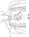
- FIG. 3A depicts a catheter 140 that has been inserted into an internal jugular vein 25 of the patient 50.
- the catheter 140 is the declotting catheter of the vascular access assembly declotting system according to the invention.
- a vascular access assembly 100 is disposed in the patient 50.
- a practitioner may make an incision or a third incision 8 at or adjacent a neck of the patient 50. The practitioner may then dispose at least a portion of the catheter 140 through the incision 8 and into at least a portion of the jugular vein 25.
- the practitioner may then displace the catheter 140 through at least a portion of the vasculature of the patient 50 such that a central end portion 142 of the catheter 140 is displaced through the jugular vein, a brachiocephalic vein, and/or a superior vena cava, and into at least a portion of the right atrium 27 of the heart 20.
- the practitioner may displace the catheter 140 through the right internal jugular vein 25, the right brachiocephalic vein 23, and the superior vena cava 21, and into at least a portion of the right atrium 27 of the heart 20.
- the practitioner may displace the catheter 140 from the left lateral side of the patient 50, for example, through the left internal jugular vein, the left brachiocephalic vein, the superior vena cava 21, and into at least a portion of the right atrium 27 of the heart 20. Due to the disposition of the first tubular conduit 110 within at least a portion of the vasculature on the right lateral side of the patient 50 ( e.g ., within the right brachiocephalic vein 23), access to the right atrium 27 for the catheter 140 may be less obstructed from the left lateral side of the patient 50.
- an inside diameter of the right brachiocephalic vein 23 may be too narrow or small for passage of two elongate medical devices (e.g ., the first tubular conduit 110 and the catheter 140). Accordingly, access to the right atrium 27 from the left lateral side of the patient 50 may avoid interactions or obstructions between the catheter 140 and the first tubular conduit 110 along at least a portion of a path of the catheter 140 through the vasculature to the right atrium 27.
- the catheter 140 may be coupled to the first tubular conduit 110 as shown in FIG. 3C .
- the central end portion 142 of the catheter 140 may be coupled to the central end portion 112 of the first tubular conduit 110.
- methods (not claimed) of declotting or removing a clot from the vascular access assembly 100 within the patient 50 may include inserting the central end portion 142 of the catheter 140 into the patient 50.
- the central end portion 142 of the catheter 140 may be displaced through at least a portion of the vasculature of the patient 50 such that the central end portion 142 of the catheter 140 is disposed within the right atrium 27 of the heart 20 of the patient 50.
- the central end portion 142 of the catheter 140 may be disposed within the right atrium 27 via the internal jugular vein 25 ( e.g., the right internal jugular vein) as depicted in FIGS. 3A-3C .
- the central end portion 142 of the catheter 140 may be disposed within the right atrium 27 via a femoral vein 47 (e.g., the right femoral vein) as described below (see, e.g., FIGS. 4A-4C ).
- a femoral vein 47 e.g., the right femoral vein
- Methods (not claimed) of declotting the vascular access assembly 100 may include coupling at least a portion of the central end portion 142 of the catheter 140 to at least a portion of a central end portion of the vascular access assembly 100 ( e.g., the central end portion 112 of the first tubular conduit 110).
- the central end portion 142 of the catheter 140 may be coupled to the central end portion of the vascular access assembly 100 within the right atrium 27 ( see , e.g., FIG. 3C ).
- Methods (not claimed) of declotting the vascular access assembly 100 may include evacuating a clot from within a portion of the vascular access assembly 100.
- the clot may be evacuated from within the portion of the vascular access assembly 100 via at least a portion of the catheter 140 ( e.g. , via a lumen 144 of the catheter 140).
- the methods may include applying a suction force on the catheter 140 ( e.g., on the lumen 144 of the catheter 140) such that at least a portion of the suction force may be applied on the vascular access assembly 100 ( e.g., on a lumen of the first tubular conduit 110) to evacuate the clot.
- a vacuum source may be coupled to or placed in fluid communication with a peripheral end of the catheter 140.
- the vacuum source may be a component of the vascular access assembly declotting system.
- the vacuum source may be activated ( e.g ., by the practitioner) such that the suction force is applied on the catheter 140 and/or the vascular access assembly 100.
- Other methods of applying a suction force on the clot via the catheter 140 are also within the scope of this disclosure.
- Methods (not claimed) of declotting the vascular access assembly 100 may further include flushing (e.g ., with a fluid such as a saline solution) a portion of the vascular access assembly 100.
- the flushing may act to displace or loosen the clot or at least a portion of the clot such that the clot may be displaced from within the vascular access assembly 100 to the lumen 144 of the catheter 140.
- Methods (not claimed) of declotting the vascular access assembly 100 may also include displacing the clot or at least a portion of the clot from within the vascular access assembly 100 to the lumen 144 of the catheter 140 and grinding or macerating at least a portion of the clot ( e.g ., with a macerator) as the clot is displaced from within the vascular access assembly 100 to the lumen 144 of the catheter 140. Grinding or macerating of the clot may aid or ease displacement of the clot through the lumen 144 of the catheter 140.
- Embodiments of catheters including a macerator are discussed in further detail below in reference to FIG. 5 .
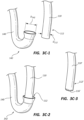
- FIG. 3C-1 depicts the central end portion 142 of the catheter 140 and the central end portion 112 of the first tubular conduit 110 in a decoupled configuration
- FIG. 3C-2 depicts the central end portion 142 of the catheter 140 and the central end portion 112 of the first tubular conduit 110 in a coupled configuration.
- at least a portion of the central end portion 142 of the catheter 140 may be funnel shaped.
- the funnel shape may aid in the coupling of the catheter 140 to the first tubular conduit 110.
- an inside surface of the funnel-shaped central end portion 142 may guide the central end portion 112 of the first tubular conduit 110 into at least a portion of the catheter 140 such that the first tubular conduit 110 and the catheter 140 may be coupled to each other.
- an internal diameter D 142 of at least a portion of the central end portion 142 of the catheter 140 can be greater than an external diameter D 112 of at least a portion of the central end portion 112 of the first tubular conduit 110. Accordingly, at least a portion of the central end portion 142 of the catheter 140 may be displaceable around at least a portion of the central end portion 112 of the first tubular conduit 110.
- the coupling of the central end portion 142 of the catheter 140 to the central end portion 112 of the first tubular conduit 110 can form a substantially fluid-tight seal.
- the catheter 140 may be coupled to the first tubular conduit 110 such that the contents of the catheter 140 and/or the first tubular conduit 110 ( e.g., a portion of a clot) do not leak into the right atrium 27.
- the central end portion 142 of the catheter 140 may be substantially J shaped.
- the central end portion 142 of the catheter 140 may have a low-profile state and a deployed state.
- the low-profile state may be substantially linear such that the central end portion 142 of the catheter 140 may be displaced through the vasculature of the patient 50 more easily and/or such that the central end portion 142 of the catheter 140 is atraumatic.
- the central end portion 142 of the catheter 140 when in the low-profile state, the central end portion 142 of the catheter 140 may be configured to avoid or limit damaging the vasculature.
- the deployed state may be substantially J shaped.
- the central end portion 142 of the catheter 140 may transition between the low-profile state (e.g ., a low-profile configuration) and the deployed state (e.g. , the J-shaped configuration).
- the low-profile state e.g ., a low-profile configuration
- the deployed state e.g. , the J-shaped configuration
- the practitioner may actuate the catheter 140 such that the central end portion 142 of the catheter 140 transitions from the low-profile state to the deployed state.
- the practitioner may pull on a wire that results in bending or curving of at least a portion of the central end portion 142.
- the central end portion 142 When in the deployed state, the central end portion 142 may be configured to be displaced over and/or around at least a portion of the central end portion 112 of the first tubular conduit 110 such that the catheter 140 may be coupled to the first tubular conduit 110.
- the practitioner may displace the catheter 140 peripherally relative to the heart 20 and dispose the central end portion 142 of the catheter 140 around and/or over at least a portion of the central end portion 112 of the first tubular conduit 110.
- the central end portion 142 of the catheter 140 may include a purse string mechanism or an iris mechanism (not shown).
- the purse string mechanism may be disposed at or adjacent a central end of the central end portion 142 of the catheter 140.
- the purse string mechanism may include a suture or wire that is disposed around a circumference of the central end portion 142 of the catheter 140.
- the purse string mechanism may be configured to transition the central end portion 142 of the catheter 140 between an open state and a closed state. When in the closed state, the central end portion 142 of the catheter 140 may be configured to form a seal between an inside surface of at least a portion of the central end portion 142 of the catheter 140 and at least a portion of an outside surface of the central end portion 112 of the first tubular conduit 110.
- the vascular access assembly 100 forming part of the vascular access device declotting system according to the invention includes a first tubular conduit 110 having a central end portion 112 for disposal within the heart 20 of the patient 50.
- the vascular access assembly 100 further includes a second tubular conduit 120 having a peripheral end 128 coupled to a vessel of the patient 50.
- a peripheral end 114 of the first tubular conduit 110 is releasably coupled ( by an adaptor 122, as a connector 122), to a central end 126 of the second tubular conduit 120.
- a flow path can extend from the vessel to the heart 20 via the first and second tubular conduits 110, 120.
- the flow path may extend from a brachial artery or an arteriovenous graft to the right atrium 27.
- Methods (not claimed) of declotting the vascular access assembly 100 may further include decoupling the first tubular conduit 110 and the second tubular conduit 120, for example, at the adaptor 122.
- the practitioner may then couple a flushing mechanism (not shown) to the peripheral end 114 of the first tubular conduit 110.
- the flushing mechanism may be a component of the vascular access assembly declotting system.
- the flushing mechanism may include a flushing catheter, wherein a peripheral end portion of the flushing catheter is in fluid communication with a fluid source (e.g. , a source of a saline solution or another suitable fluid).
- the practitioner may displace a fluid through at least a portion of the flushing mechanism and through at least a portion of the first tubular conduit 110. Stated another way, the practitioner may flush the first tubular conduit 110 such that a clot is displaced from within the first tubular conduit 110 to the lumen 144 of the catheter 140.
- Methods (not claimed) of declotting or removing a clot from the vascular access assembly 100 within the patient 50 can include: accessing a jugular vein of the patient 50, inserting the central end portion 142 of the catheter 140 into the jugular vein, displacing the catheter 140 such that the central end portion 142 of the catheter 140 is disposed within the right atrium 27 of the heart 20 of the patient 50, coupling the central end portion 142 of the catheter 140 to the central end portion 112 of the vascular access assembly 100 disposed within the right atrium 27, and/or evacuating the clot from within a portion of the vascular access assembly 100 via the catheter 140.
- the methods (not claimed) may further include evacuating or sucking the clot from within at least a portion of the vascular access assembly 100 and through the catheter 140 to evacuate the clot from within the vascular access assembly 100.
- Displacing the catheter 140 such that the central end portion 142 of the catheter 140 is disposed within the right atrium 27 may further include displacing the central end portion 142 of the catheter 140 through at least a portion of each of the right internal jugular vein 25, the right brachiocephalic vein 23, and/or the superior vena cava 21 of the patient 50.
- Other methods of accessing the right atrium 27 are also within the scope of this disclosure (e.g ., via the vasculature of the left lateral side of the patient 50 as discussed above or via a femoral vein as described in further detail below).
- FIG. 3C-3 depicts a central end portion 112' of a first tubular conduit 110'.
- the central end portion 112' of the first tubular conduit 110' may include a purse string mechanism 116' or an iris mechanism.
- the purse string mechanism 116' may be disposed at or adjacent a central end of the central end portion 112' of the first tubular conduit 110'.
- the purse string mechanism 116' may include a suture or wire that is disposed around a circumference of the central end portion 112' of the first tubular conduit 110'.
- the purse string mechanism 116' may be configured to transition the central end portion 112' of the first tubular conduit 110' between an open state and a closed state. When in the closed state, the central end portion 112' of the first tubular conduit 110' may be configured to form a seal at or adjacent the central end portion 112' of the first tubular conduit 110'.
- the purse string mechanism 116' may be utilized to close the central end portion 112' of the first tubular conduit 110' prior to removal of the first tubular conduit 110'.
- a practitioner may desire to remove and replace a tubular conduit from an implanted assembly, due to clotting of that conduit, for example.
- Use of a purse string, such as purse string mechanism 116' may prevent a clot from exiting the conduit while that conduit is being removed.
- a practitioner may close the end of the conduit via a purse string or other mechanism, prior to removing the conduit from the patient's body. A replacement conduit may then be introduced to replace the withdrawn conduit.
- Methods (not claimed) of declotting a vascular access assembly may include decoupling the first tubular conduit 110' and a second tubular conduit (e.g., at an adaptor) and the method may utilize a vacuum.
- the practitioner may then couple a vacuum source to a peripheral end of the first tubular conduit 110'.
- the vacuum source may be coupled to the first tubular conduit 110' via a vacuum catheter.
- the practitioner may also transition the central end portion 112' of the first tubular conduit 110' to the closed state, for example, by actuating the purse string mechanism 116'.
- the vacuum source and/or the vacuum catheter may be components of the vascular access assembly declotting system.
- the vacuum source may be activated ( e.g ., by the practitioner) such that a suction force is applied on the first tubular conduit 110' and a clot disposed within the first tubular conduit 110' can be displaced from within, evacuated from, or sucked out of the first tubular conduit 110'.
- Disposition of the purse string mechanism 116' and/or the central end portion 112' of the first tubular conduit 110' in the closed state may limit or prevent the clot, or a portion of the clot, from exiting the first tubular conduit 110' at the central end portion 112'. Accordingly, the clot may be limited or prevented from entering or being lost into the vena cava and/or the heart of the patient.
- FIGS. 4A-4C-2 depict an embodiment of a vascular access assembly 200 that resembles the vascular access assembly 100 described above in certain respects. Accordingly, like features are designated with like reference numerals, with the leading digits incremented to "2."
- the embodiment depicted in FIGS. 4A-4C-2 includes a first tubular conduit 210 that may, in some respects, resemble the first tubular conduit 110 of FIGS. 1-3C-2 .
- Relevant disclosure set forth above regarding similarly identified features thus may not be repeated hereafter.
- specific features of the vascular access assembly 100 and related components shown in FIGS. 1-3C-2 may not be shown or identified by a reference numeral in the drawings or specifically discussed in the written description that follows.
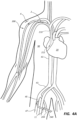
- FIG. 4A depicts a catheter 240 that has been inserted into a femoral vein 47 of the patient 50.
- a vascular access assembly 200 is disposed in the patient 50.
- a practitioner may make an incision or a fourth incision 11 at or adjacent a thigh or an upper leg of the patient 50. The practitioner may then dispose at least a portion of the catheter 240 through the incision 11 and into at least a portion of the femoral vein 47.
- the practitioner may then displace the catheter 240 through at least a portion of the vasculature of the patient 50 such that a central end portion 242 of the catheter 240 is displaced through a femoral vein, an external iliac vein, a common iliac vein, and/or an inferior vena cava, and into at least a portion of the right atrium 27 of the heart 20.
- femoral access may also be performed through either the right lateral side or the left lateral side of the patient 50. As illustrated in FIG.
- the practitioner may displace the catheter 240 through the right femoral vein 47, the right external iliac vein 45, the right common iliac vein 43, and the inferior vena cava 41, and into at least a portion of the right atrium 27 of the heart 20.
- the catheter 240 may be coupled to the first tubular conduit 210 as shown in FIG. 4C .
- the central end portion 242 of the catheter 240 may be coupled to a central end portion 212 of the first tubular conduit 210.
- Methods (not claimed) of declotting the vascular access assembly 200 may include coupling at least a portion of the central end portion 242 of the catheter 240 to at least a portion of a central end portion of the vascular access assembly 200 ( i.e., the central end portion 212 of the first tubular conduit 210).
- the central end portion 242 of the catheter 240 may be coupled to the central end portion of the vascular access assembly 200 within the right atrium 27 (see, e.g., FIG. 4C ).
- Methods (not claimed) of declotting the vascular access assembly 200 may include evacuating a clot from within a portion of the vascular access assembly 200.
- the clot may be evacuated from within the portion of the vascular access assembly 200 via at least a portion of the catheter 240 ( e.g. , via a lumen 244 of the catheter 240).
- the methods may include applying a suction force on the catheter 240 such that at least a portion of the suction force may be applied on the vascular access assembly 200 ( e.g., on a lumen of the first tubular conduit 210) to evacuate the clot.
- methods of declotting the vascular access assembly 200 may also include flushing (e.g ., with a fluid such as a saline solution) a portion of the vascular access assembly 200.
- FIG. 4C-1 depicts the central end portion 242 of the catheter 240 and the central end portion 212 of the first tubular conduit 210 in a decoupled configuration
- FIG. 4C-2 depicts the central end portion 242 of the catheter 240 and the central end portion 212 of the first tubular conduit 210 in a coupled configuration.
- an internal diameter D 242 of at least a portion of the central end portion 242 of the catheter 240 can be greater than an external diameter D 212 of at least a portion the central end portion 212 of the first tubular conduit 210 ( e.g., the central end portion of the vascular access assembly 200).
- at least a portion of the central end portion 242 of the catheter 240 may be displaceable around at least a portion of the central end portion 212 of the first tubular conduit 210.
- At least a portion of the central end portion 242 of the catheter 240 may be substantially linear.
- the practitioner may displace the catheter 240 centrally relative to the heart 20 and dispose the central end portion 242 of the catheter 240 around and/or over at least a portion of the central end portion 212 of the first tubular conduit 210 ( e.g., to form a seal between the catheter 240 and the first tubular conduit 210).
- Other embodiments of the catheter 240 and/or the central end portion 242 of the catheter 240, as disclosed herein, may be used in methods of femoral vein access to the right atrium 27.
- the catheter 240 may include a purse string mechanism, as described above, such that the catheter 240 may form a seal between an inside surface of at least a portion of the central end portion 242 of the catheter 240 and at least a portion of an outside surface of the central end portion 212 of the first tubular conduit 210 when in the closed state.
- Methods (not claimed) of declotting or removing a clot from the vascular access assembly 200 within the patient 50 can include: accessing the femoral vein 47 of the patient 50, inserting the central end portion 242 of the catheter 240 into at least a portion of the femoral vein 47, displacing the catheter 240 such that the central end portion 242 of the catheter 240 is disposed within the right atrium 27 of the heart 20 of the patient 50, coupling the central end portion 242 of the catheter 240 to the central end portion 212 of the first tubular conduit 210 ( i.e., the central end portion of the vascular access assembly 200) disposed within the right atrium 27, and/or evacuating the clot from within a portion of the vascular access assembly 200 via the catheter 240.
- the methods may further include sucking the clot (e.g ., using a vacuum mechanism) from within the vascular access assembly 200 and through the catheter 240 to evacuate the clot from within the vascular access assembly 200.
- Displacing the catheter 240 such that the central end portion 242 of the catheter 240 is disposed within at least a portion of the right atrium 27 may include displacing the central end portion 242 of the catheter 240 through each of the femoral vein 47, the external iliac vein 45, the common iliac vein 43, and/or the inferior vena cava 41 of the patient 50.
- other methods of accessing the right atrium 27 are also within the scope of this disclosure.
- FIG. 5 illustrates a central end portion 342 of a catheter 340.
- the central end portion 342 of the catheter 340 may be funnel shaped.
- the catheter 340 can include a macerator 346 coupled to or disposed within at least a portion of the catheter 340. As depicted, at least a portion of the macerator 346 may be disposed at or adjacent the central end portion 342 of the catheter 340.
- a practitioner may actuate the macerator 346 such that the macerator 346 may grind or macerate a clot as the clot passes from within the vascular access assembly to the catheter 340 or a lumen 344 of the catheter 340. The grinding or macerating of the clot may aid or ease displacement of the clot through the catheter 340 or the lumen 344 of the catheter 340.
- a practitioner may advance a balloon through a clotted conduit from a peripheral position toward a central position.
- a clot may be disposed in a portion of the vascular access assembly 100, such as within the first tubular conduit 110.
- a practitioner may decouple the peripheral end 114 of the first tubular conduit 110 and advance a low-profile balloon through the first tubular conduit 110 toward the central end portion 112 of the first tubular conduit 110.
- the balloon may be advanced in a low-profile, deflated configuration and may traverse the clot without displacing the clot in the central direction.
- the balloon may then be inflated and withdrawn in the peripheral direction.
- the inflated balloon may then be used to pull the clot in the peripheral direction and out of the peripheral end 114 of the first tubular conduit 114.
- Methods utilizing balloons may be utilized in any of the systems, and any of the locations within the body, described herein in connection with other embodiments or examples.
- Any methods (none of which are claimed) disclosed herein include one or more steps or actions for performing the described method.
- the method steps and/or actions may be interchanged with one another.
Landscapes
- Health & Medical Sciences (AREA)
- Life Sciences & Earth Sciences (AREA)
- Heart & Thoracic Surgery (AREA)
- Animal Behavior & Ethology (AREA)
- Engineering & Computer Science (AREA)
- Biomedical Technology (AREA)
- General Health & Medical Sciences (AREA)
- Public Health (AREA)
- Veterinary Medicine (AREA)
- Surgery (AREA)
- Anesthesiology (AREA)
- Hematology (AREA)
- Vascular Medicine (AREA)
- Pulmonology (AREA)
- Medical Informatics (AREA)
- Molecular Biology (AREA)
- Nuclear Medicine, Radiotherapy & Molecular Imaging (AREA)
- Biophysics (AREA)
- Cardiology (AREA)
- Gastroenterology & Hepatology (AREA)
- Orthopedic Medicine & Surgery (AREA)
- External Artificial Organs (AREA)
Claims (14)
- System zum Entfernen von Gerinnseln aus einer
Gefäßzugangsvorrichtung, umfassend:eine Gefäßzugangsanordnung (100), umfassend:eine erste röhrenförmige Leitung (110), die einen ersten mittigen Endabschnitt (112) zur Anordnung in einem Herzen eines Patienten umfasst,eine zweite röhrenförmige Leitung (120) zum Gekoppelt-Werden mit einem Gefäß, undmindestens ein Verbindungsstück (122), das mit der ersten röhrenförmigen Leitung (110) und der zweiten röhrenförmigen Leitung (120) gekoppelt ist, so dass sich ein Strömungsweg über die erste röhrenförmige Leitung und die zweite röhrenförmige Leitung erstreckt, undeinen Katheter (140) zum Entfernen von Gerinnseln, der einen zweiten mittigen Endabschnitt umfasst,wobei der erste mittige Endabschnitt (112) der ersten röhrenförmigen Leitung (110) dafür gestaltet ist, mit dem zweiten mittigen Endabschnitt (142) des Katheters (140) zum Entfernen von Gerinnseln gekoppelt zu werden, undwobei das System derart gestaltet ist, dass das Koppeln des ersten mittigen Endabschnitts (112) der ersten röhrenförmigen Leitung (110) mit dem zweiten mittigen Endabschnitt (142) des Katheters (140) zum Entfernen von Gerinnseln dafür gestaltet ist, im Gefäßsystem des Patienten ausgeführt zu werden. - System zum Entfernen von Gerinnseln aus einer Gefäßzugangsvorrichtung nach Anspruch 1, wobei der Katheter (140) zum Entfernen von Gerinnseln einen Zugdraht umfasst, der dafür gestaltet ist, den zweiten mittigen Endabschnitt (142) zu biegen.
- System zum Entfernen von Gerinnseln aus einer Gefäßzugangsvorrichtung nach Anspruch 2, wobei der zweite mittige Endabschnitt (142) eine J-Form umfasst.
- System zum Entfernen von Gerinnseln aus einer Gefäßzugangsvorrichtung nach einem der vorhergehenden Ansprüche, wobei der zweite mittige Endabschnitt (142) trichterförmig ist.
- System zum Entfernen von Gerinnseln aus einer Gefäßzugangsvorrichtung nach einem der vorhergehenden Ansprüche, wobei ein Innendurchmesser des zweiten mittigen Endabschnitts (142) größer ist als ein Außendurchmesser des ersten mittigen Endabschnitts (112).
- System zum Entfernen von Gerinnseln aus einer Gefäßzugangsvorrichtung nach einem der vorhergehenden Ansprüche, wobei der Katheter (140) zum Entfernen von Gerinnseln einen Tabaksbeutelmechanismus umfasst, der dafür gestaltet ist, den Innendurchmesser des zweiten mittigen Endabschnitts (142) zu verändern, um eine Dichtung zwischen einer Innenoberfläche des zweiten mittigen Endabschnitts (142) und einer Außenoberfläche des ersten mittigen Endabschnitts (112) zu bilden.
- System zum Entfernen von Gerinnseln aus einer Gefäßzugangsvorrichtung nach einem der vorhergehenden Ansprüche, wobei die erste röhrenförmige Leitung (110) einen Tabaksbeutelverschluss umfasst, der dafür gestaltet ist, den ersten mittigen Endabschnitt (112) von einem offenen Zustand in einen geschlossenen Zustand zu überführen.
- System zum Entfernen von Gerinnseln aus einer Gefäßzugangsvorrichtung nach einem der Ansprüche 1 bis 6, wobei die erste röhrenförmige Leitung (110) einen Irismechanismus umfasst, der dafür gestaltet ist, den ersten mittigen Endabschnitt (112) von einem offenen Zustand in einen geschlossenen Zustand zu überführen.
- System zum Entfernen von Gerinnseln aus einer Gefäßzugangsvorrichtung nach einem der vorhergehenden Ansprüche, wobei der Katheter (140) zum Entfernen von Gerinnseln ferner einen Gerinnselzerkleinerer (346) umfasst, der dafür gestaltet ist, ein Gerinnsel zu zerkleinern oder zu zerreiben.
- System zum Entfernen von Gerinnseln aus einer Gefäßzugangsvorrichtung nach einem der vorhergehenden Ansprüche, ferner umfassend einen Spülmechanismus.
- System zum Entfernen von Gerinnseln aus einer Gefäßzugangsvorrichtung nach Anspruch 10, wobei der Spülmechanismus einen Spülkatheter umfasst, der dafür gestaltet ist, mit der ersten röhrenförmigen Leitung (110) und einer Fluidquelle gekoppelt zu werden.
- System zum Entfernen von Gerinnseln aus einer Gefäßzugangsvorrichtung nach einem der vorhergehenden Ansprüche, ferner umfassend einen Vakuummechanismus.
- System zum Entfernen von Gerinnseln aus einer Gefäßzugangsvorrichtung nach Anspruch 12, wobei der Vakuummechanismus eine Vakuumquelle und einen Vakuumkatheter umfasst, der dafür gestaltet ist, mit der ersten röhrenförmigen Leitung (110) gekoppelt zu werden.
- System zum Entfernen von Gerinnseln aus einer Gefäßzugangsvorrichtung nach einem der vorhergehenden Ansprüche, ferner umfassend einen Ballonkatheter, der dafür gestaltet ist, durch die erste röhrenförmige Leitung (110) hindurchzutreten.
Applications Claiming Priority (2)
| Application Number | Priority Date | Filing Date | Title |
|---|---|---|---|
| US201762467554P | 2017-03-06 | 2017-03-06 | |
| PCT/US2018/020614 WO2018164945A1 (en) | 2017-03-06 | 2018-03-02 | Vascular access assembly declotting systems and methods |
Publications (3)
| Publication Number | Publication Date |
|---|---|
| EP3592401A1 EP3592401A1 (de) | 2020-01-15 |
| EP3592401A4 EP3592401A4 (de) | 2021-01-06 |
| EP3592401B1 true EP3592401B1 (de) | 2024-09-18 |
Family
ID=63357536
Family Applications (1)
| Application Number | Title | Priority Date | Filing Date |
|---|---|---|---|
| EP18764826.6A Active EP3592401B1 (de) | 2017-03-06 | 2018-03-02 | Systeme und verfahren zur befreiung einer gefässzugangsanordnung von gerinnseln |
Country Status (4)
| Country | Link |
|---|---|
| US (1) | US11026704B2 (de) |
| EP (1) | EP3592401B1 (de) |
| ES (1) | ES2991874T3 (de) |
| WO (1) | WO2018164945A1 (de) |
Families Citing this family (4)
| Publication number | Priority date | Publication date | Assignee | Title |
|---|---|---|---|---|
| EP3568173A4 (de) | 2017-01-12 | 2020-11-25 | Merit Medical Systems, Inc. | Verfahren und systeme zur auswahl und verwendung von verbindern zwischen leitungen |
| EP3651829A4 (de) * | 2017-07-14 | 2021-04-21 | Merit Medical Systems, Inc. | Lösbare leitungsverbinder |
| WO2021086543A1 (en) * | 2019-10-29 | 2021-05-06 | Bard Access Systems, Inc. | Systems, devices, and methods for thrombolysis |
| WO2024086567A1 (en) * | 2022-10-20 | 2024-04-25 | Merit Medical Systems, Inc. | Vascular access assemblies |
Family Cites Families (283)
| Publication number | Priority date | Publication date | Assignee | Title |
|---|---|---|---|---|
| US3357432A (en) | 1965-02-09 | 1967-12-12 | Edwards Lab Inc | Anastomotic coupling |
| US3435823A (en) | 1966-04-11 | 1969-04-01 | Miles Lowell Edwards | Anastomotic coupling with anti-pulse ring means |
| US3490438A (en) | 1967-06-08 | 1970-01-20 | Atomic Energy Commission | Perfusion chamber and cannulae therefor |
| US3683926A (en) | 1970-07-09 | 1972-08-15 | Dainippon Pharmaceutical Co | Tube for connecting blood vessels |
| US3826257A (en) | 1972-07-14 | 1974-07-30 | T Buselmeier | Prosthetic shunt |
| US3818511A (en) | 1972-11-17 | 1974-06-25 | Medical Prod Corp | Medical prosthesis for ducts or conduits |
| US3814137A (en) | 1973-01-26 | 1974-06-04 | Baxter Laboratories Inc | Injection site for flow conduits containing biological fluids |
| US3853126A (en) | 1973-11-15 | 1974-12-10 | Heyer Schulte Corp | Artery-to-vein shunt |
| US3882862A (en) | 1974-01-11 | 1975-05-13 | Olga Berend | Arteriovenous shunt |
| US3998222A (en) | 1974-04-15 | 1976-12-21 | Shihata Alfred A | Subcutaneous arterio-venous shunt with valve |
| US4076023A (en) | 1975-08-01 | 1978-02-28 | Erika, Inc. | Resealable device for repeated access to conduit lumens |
| US4184489A (en) | 1976-10-06 | 1980-01-22 | Cordis Dow Corp. | Infusion tube access site |
| US4133312A (en) | 1976-10-13 | 1979-01-09 | Cordis Dow Corp. | Connector for attachment of blood tubing to external arteriovenous shunts and fistulas |
| US4214586A (en) | 1978-11-30 | 1980-07-29 | Ethicon, Inc. | Anastomotic coupling device |
| US4496350A (en) | 1980-04-08 | 1985-01-29 | Renal Systems, Inc. | Blood access device |
| US4318401A (en) | 1980-04-24 | 1982-03-09 | President And Fellows Of Harvard College | Percutaneous vascular access portal and catheter |
| DE3019996A1 (de) | 1980-05-24 | 1981-12-03 | Institute für Textil- und Faserforschung Stuttgart, 7410 Reutlingen | Hohlorgan |
| US4366819A (en) | 1980-11-17 | 1983-01-04 | Kaster Robert L | Anastomotic fitting |
| US4441215A (en) | 1980-11-17 | 1984-04-10 | Kaster Robert L | Vascular graft |
| US4427219A (en) | 1981-01-26 | 1984-01-24 | Robroy Industries | Compression coupling |
| US4496349A (en) | 1981-05-08 | 1985-01-29 | Renal Systems, Inc. | Percutaneous implant |
| US4503568A (en) | 1981-11-25 | 1985-03-12 | New England Deaconess Hospital | Small diameter vascular bypass and method |
| SE445884B (sv) | 1982-04-30 | 1986-07-28 | Medinvent Sa | Anordning for implantation av en rorformig protes |
| US4447237A (en) | 1982-05-07 | 1984-05-08 | Dow Corning Corporation | Valving slit construction and cooperating assembly for penetrating the same |
| SE446372B (sv) | 1983-02-03 | 1986-09-08 | Medinvent Sa | Blodkerlsprotes for anvendning som shunt mellan blodkerl |
| US4550447A (en) | 1983-08-03 | 1985-11-05 | Shiley Incorporated | Vascular graft prosthesis |
| GB8407706D0 (en) | 1984-03-24 | 1984-05-02 | Edgealpha Ltd | Lining pipelines in passageways |
| US4917087A (en) | 1984-04-10 | 1990-04-17 | Walsh Manufacturing (Mississuaga) Limited | Anastomosis devices, kits and method |
| US4772268A (en) | 1984-05-25 | 1988-09-20 | Cook Incorporated | Two lumen hemodialysis catheter |
| US4619641A (en) | 1984-11-13 | 1986-10-28 | Mount Sinai School Of Medicine Of The City University Of New York | Coaxial double lumen anteriovenous grafts |
| US5042161A (en) | 1985-10-07 | 1991-08-27 | Joseph Hodge | Intravascular sizing method and apparatus |
| JPS62112567A (ja) | 1985-11-12 | 1987-05-23 | 株式会社クラレ | 複合チユ−ブおよび該チユ−ブを用いる流体の採取または注入方法 |
| US4790826A (en) | 1986-03-28 | 1988-12-13 | Elftman Nancy W | Percutaneous access port |
| US4753236A (en) | 1986-04-08 | 1988-06-28 | Healey Maureen A | Temporary anastomotic device |
| SE453258B (sv) | 1986-04-21 | 1988-01-25 | Medinvent Sa | Elastisk, sjelvexpanderande protes samt forfarande for dess framstellning |
| US4734094A (en) | 1986-06-09 | 1988-03-29 | Jacob Erwin T | Catheter and method for cholangiography |
| SE455834B (sv) | 1986-10-31 | 1988-08-15 | Medinvent Sa | Anordning for transluminal implantation av en i huvudsak rorformig, radiellt expanderbar protes |
| US4723948A (en) | 1986-11-12 | 1988-02-09 | Pharmacia Nu Tech | Catheter attachment system |
| US4771777A (en) | 1987-01-06 | 1988-09-20 | Advanced Cardiovascular Systems, Inc. | Perfusion type balloon dilatation catheter, apparatus and method |
| US5061276A (en) | 1987-04-28 | 1991-10-29 | Baxter International Inc. | Multi-layered poly(tetrafluoroethylene)/elastomer materials useful for in vivo implantation |
| IT1204717B (it) | 1987-06-16 | 1989-03-10 | Claber Spa | Dispositivo di accesso vascolare,particolarmente per trattamenti di depurazione del sangue |
| US5026513A (en) | 1987-10-19 | 1991-06-25 | W. L. Gore & Associates, Inc. | Process for making rapidly recoverable PTFE |
| US4877661A (en) | 1987-10-19 | 1989-10-31 | W. L. Gore & Associates, Inc. | Rapidly recoverable PTFE and process therefore |
| US4822341A (en) | 1987-11-20 | 1989-04-18 | Impra, Inc. | Vascular access fistula |
| US4919127A (en) | 1988-05-03 | 1990-04-24 | Pell Donald M | Endotracheal tube connector |
| US5104402A (en) | 1988-05-25 | 1992-04-14 | Trustees Of The University Of Pennsylvania | Prosthetic vessels for stress at vascular graft anastomoses |
| US4929236A (en) | 1988-05-26 | 1990-05-29 | Shiley Infusaid, Inc. | Snap-lock fitting catheter for an implantable device |
| US4898591A (en) | 1988-08-09 | 1990-02-06 | Mallinckrodt, Inc. | Nylon-PEBA copolymer catheter |
| US5053023A (en) | 1988-10-25 | 1991-10-01 | Vas-Cath Incorporated | Catheter for prolonged access |
| US4930502A (en) | 1989-01-26 | 1990-06-05 | Chen Fusen H | Anastomosis device |
| US5192289A (en) | 1989-03-09 | 1993-03-09 | Avatar Design And Development, Inc. | Anastomosis stent and stent selection system |
| US5041098A (en) | 1989-05-19 | 1991-08-20 | Strato Medical Corporation | Vascular access system for extracorporeal treatment of blood |
| US4955899A (en) | 1989-05-26 | 1990-09-11 | Impra, Inc. | Longitudinally compliant vascular graft |
| US5569182A (en) | 1990-01-08 | 1996-10-29 | The Curators Of The University Of Missouri | Clot resistant multiple lumen catheter and method |
| US5405320A (en) | 1990-01-08 | 1995-04-11 | The Curators Of The University Of Missouri | Multiple lumen catheter for hemodialysis |
| US5350360A (en) | 1990-03-01 | 1994-09-27 | Michigan Transtech Corporation | Implantable access devices |
| US5064435A (en) | 1990-06-28 | 1991-11-12 | Schneider (Usa) Inc. | Self-expanding prosthesis having stable axial length |
| US5336616A (en) | 1990-09-12 | 1994-08-09 | Lifecell Corporation | Method for processing and preserving collagen-based tissues for transplantation |
| DE69116130T2 (de) | 1990-10-18 | 1996-05-15 | Ho Young Song | Selbstexpandierender, endovaskulärer dilatator |
| JP3137646B2 (ja) | 1991-04-05 | 2001-02-26 | ボストン サイエンティフィック コーポレイション | 硬度調節可能な可変カテーテル器具 |
| US5171227A (en) | 1991-04-16 | 1992-12-15 | The Curators Of The University Of Missouri | Separable peritoneal dialysis catheter |
| US5399168A (en) | 1991-08-29 | 1995-03-21 | C. R. Bard, Inc. | Implantable plural fluid cavity port |
| DE4129782C1 (de) | 1991-09-07 | 1992-10-08 | Hans Dipl.-Ing. Dr.Med. 3015 Wennigsen De Haindl | |
| US5197976A (en) | 1991-09-16 | 1993-03-30 | Atrium Medical Corporation | Manually separable multi-lumen vascular graft |
| US5192310A (en) | 1991-09-16 | 1993-03-09 | Atrium Medical Corporation | Self-sealing implantable vascular graft |
| US5282860A (en) | 1991-10-16 | 1994-02-01 | Olympus Optical Co., Ltd. | Stent tube for medical use |
| US5171305A (en) | 1991-10-17 | 1992-12-15 | Imagyn Medical, Inc. | Linear eversion catheter with reinforced inner body extension |
| US5866217A (en) | 1991-11-04 | 1999-02-02 | Possis Medical, Inc. | Silicone composite vascular graft |
| US5474268A (en) | 1992-02-10 | 1995-12-12 | Yu; Michael | Agricultural and industrial tie |
| US5647855A (en) | 1992-05-06 | 1997-07-15 | Trooskin; Stanley Z. | Self-healing diaphragm in a subcutaneous infusion port |
| JPH06105798A (ja) | 1992-09-30 | 1994-04-19 | Terumo Corp | カテーテルチューブ |
| US5474563A (en) | 1993-03-25 | 1995-12-12 | Myler; Richard | Cardiovascular stent and retrieval apparatus |
| US5607463A (en) | 1993-03-30 | 1997-03-04 | Medtronic, Inc. | Intravascular medical device |
| US5531715A (en) | 1993-05-12 | 1996-07-02 | Target Therapeutics, Inc. | Lubricious catheters |
| US5735892A (en) | 1993-08-18 | 1998-04-07 | W. L. Gore & Associates, Inc. | Intraluminal stent graft |
| US5405339A (en) | 1993-09-03 | 1995-04-11 | Medtronic, Inc. | Medical connector and method for connecting medical tubing |
| US5562617A (en) | 1994-01-18 | 1996-10-08 | Finch, Jr.; Charles D. | Implantable vascular device |
| US6053901A (en) | 1994-01-18 | 2000-04-25 | Vasca, Inc. | Subcutaneously implanted cannula and method for arterial access |
| US5562618A (en) | 1994-01-21 | 1996-10-08 | Sims Deltec, Inc. | Portal assembly and catheter connector |
| US5387192A (en) | 1994-01-24 | 1995-02-07 | Sims Deltec, Inc. | Hybrid portal and method |
| US5549663A (en) | 1994-03-09 | 1996-08-27 | Cordis Corporation | Endoprosthesis having graft member and exposed welded end junctions, method and procedure |
| CA2189006A1 (en) | 1994-04-29 | 1995-11-09 | Boston Scientific Corporation | Medical prosthetic stent and method of manufacture |
| US5454790A (en) | 1994-05-09 | 1995-10-03 | Innerdyne, Inc. | Method and apparatus for catheterization access |
| DE4418910A1 (de) | 1994-05-31 | 1995-12-07 | Mouhamed Kamal Dr Med Koudaimi | Implantierbares Portsystem für Dialyse und ähnliche Anwendung |
| US5496294A (en) | 1994-07-08 | 1996-03-05 | Target Therapeutics, Inc. | Catheter with kink-resistant distal tip |
| US6309411B1 (en) | 1994-10-19 | 2001-10-30 | Medtronic Ave, Inc. | Method and apparatus to prevent stent migration |
| US5669881A (en) | 1995-01-10 | 1997-09-23 | Baxter International Inc. | Vascular introducer system incorporating inflatable occlusion balloon |
| US5591226A (en) | 1995-01-23 | 1997-01-07 | Schneider (Usa) Inc. | Percutaneous stent-graft and method for delivery thereof |
| US5904967A (en) | 1995-04-27 | 1999-05-18 | Terumo Kabushiki Kaisha | Puncture resistant medical material |
| NZ286445A (en) | 1995-05-16 | 1997-12-19 | Ivac Corp | Needleless luer connector: deformable piston occludes bore |
| US5637102A (en) | 1995-05-24 | 1997-06-10 | C. R. Bard, Inc. | Dual-type catheter connection system |
| US5674272A (en) | 1995-06-05 | 1997-10-07 | Ventritex, Inc. | Crush resistant implantable lead |
| US5743894A (en) | 1995-06-07 | 1998-04-28 | Sherwood Medical Company | Spike port with integrated two way valve access |
| CA2226635C (en) | 1995-07-07 | 2003-12-23 | W.L. Gore & Associates, Inc. | Interior liner for tubes, pipes and blood conduits |
| US5637088A (en) | 1995-09-14 | 1997-06-10 | Wenner; Donald E. | System for preventing needle displacement in subcutaneous venous access ports |
| JPH0984871A (ja) | 1995-09-25 | 1997-03-31 | Terumo Corp | 医療用チューブおよびその製造方法 |
| DE29515546U1 (de) | 1995-09-29 | 1997-01-30 | Schreiber, Hans, Dr. Dr., 69469 Weinheim | Gefäßport, insbesondere für die Hämodialyse |
| US5800512A (en) | 1996-01-22 | 1998-09-01 | Meadox Medicals, Inc. | PTFE vascular graft |
| US6428571B1 (en) | 1996-01-22 | 2002-08-06 | Scimed Life Systems, Inc. | Self-sealing PTFE vascular graft and manufacturing methods |
| US5624413A (en) | 1996-02-23 | 1997-04-29 | Medical Components, Inc. | Method for inserting a multiple catheter assembly |
| US5645532A (en) | 1996-03-04 | 1997-07-08 | Sil-Med Corporation | Radiopaque cuff peritoneal dialysis catheter |
| US5830184A (en) | 1996-03-06 | 1998-11-03 | Medical Components, Inc. | Composite catheter stabilizing devices, methods of making the same and catheter extracting device |
| US5830224A (en) | 1996-03-15 | 1998-11-03 | Beth Israel Deaconess Medical Center | Catheter apparatus and methodology for generating a fistula on-demand between closely associated blood vessels at a pre-chosen anatomic site in-vivo |
| JPH09264468A (ja) | 1996-03-28 | 1997-10-07 | Toyoda Gosei Co Ltd | ホース結合構造 |
| US5800514A (en) | 1996-05-24 | 1998-09-01 | Meadox Medicals, Inc. | Shaped woven tubular soft-tissue prostheses and methods of manufacturing |
| US5669637A (en) | 1996-05-29 | 1997-09-23 | Optimize Technologies, Inc. | Miniature fitting assembly for micro-tubing |
| US5755773A (en) | 1996-06-04 | 1998-05-26 | Medtronic, Inc. | Endoluminal prosthetic bifurcation shunt |
| US6007544A (en) | 1996-06-14 | 1999-12-28 | Beth Israel Deaconess Medical Center | Catheter apparatus having an improved shape-memory alloy cuff and inflatable on-demand balloon for creating a bypass graft in-vivo |
| US5797879A (en) | 1996-08-26 | 1998-08-25 | Decampli; William M. | Apparatus and methods for providing selectively adjustable blood flow through a vascular graft |
| US6007573A (en) | 1996-09-18 | 1999-12-28 | Microtherapeutics, Inc. | Intracranial stent and method of use |
| US6036702A (en) | 1997-04-23 | 2000-03-14 | Vascular Science Inc. | Medical grafting connectors and fasteners |
| US6019788A (en) | 1996-11-08 | 2000-02-01 | Gore Enterprise Holdings, Inc. | Vascular shunt graft and junction for same |
| US5792104A (en) | 1996-12-10 | 1998-08-11 | Medtronic, Inc. | Dual-reservoir vascular access port |
| US5931829A (en) | 1997-01-21 | 1999-08-03 | Vasca, Inc. | Methods and systems for establishing vascular access |
| US5957974A (en) | 1997-01-23 | 1999-09-28 | Schneider (Usa) Inc | Stent graft with braided polymeric sleeve |
| US6102884A (en) | 1997-02-07 | 2000-08-15 | Squitieri; Rafael | Squitieri hemodialysis and vascular access systems |
| US6231085B1 (en) | 1997-04-21 | 2001-05-15 | Irrigation Development Company | Tubing coupling and hose end combination, and related method |
| US6056762A (en) | 1997-05-22 | 2000-05-02 | Kensey Nash Corporation | Anastomosis system and method of use |
| DE19721703A1 (de) | 1997-05-23 | 1998-11-26 | Angiomed Ag | Kathetersystem mit hoher Knickfestigkeit |
| US5997562A (en) | 1997-06-13 | 1999-12-07 | Percusurge, Inc. | Medical wire introducer and balloon protective sheath |
| US6610004B2 (en) | 1997-10-09 | 2003-08-26 | Orqis Medical Corporation | Implantable heart assist system and method of applying same |
| FR2770409B1 (fr) | 1997-10-31 | 2000-06-23 | Soprane Sa | Catheter universel |
| US5931865A (en) | 1997-11-24 | 1999-08-03 | Gore Enterprise Holdings, Inc. | Multiple-layered leak resistant tube |
| US6156016A (en) | 1998-01-06 | 2000-12-05 | Maginot Vascular Systems | Catheter systems and associated methods utilizing removable inner catheter or catheters |
| US6261257B1 (en) | 1998-05-26 | 2001-07-17 | Renan P. Uflacker | Dialysis graft system with self-sealing access ports |
| DE19932956B4 (de) | 1998-07-15 | 2009-04-09 | Toyoda Gosei Co., Ltd. | Schlauchverbindung |
| US7044937B1 (en) | 1998-07-27 | 2006-05-16 | Genzyme Corporation | Universal modular surgical applicator systems |
| US6167765B1 (en) | 1998-09-25 | 2001-01-02 | The Regents Of The University Of Michigan | System and method for determining the flow rate of blood in a vessel using doppler frequency signals |
| US6261255B1 (en) | 1998-11-06 | 2001-07-17 | Ronald Jay Mullis | Apparatus for vascular access for chronic hemodialysis |
| US6171295B1 (en) | 1999-01-20 | 2001-01-09 | Scimed Life Systems, Inc. | Intravascular catheter with composite reinforcement |
| US6338724B1 (en) | 1999-03-29 | 2002-01-15 | Christos D. Dossa | Arterio-venous interconnection |
| US6368347B1 (en) | 1999-04-23 | 2002-04-09 | Sulzer Vascutek Ltd. | Expanded polytetrafluoroethylene vascular graft with coating |
| US6926724B1 (en) | 1999-05-04 | 2005-08-09 | City Of Hope | Visceral anastomotic device and method of using same |
| JP4191849B2 (ja) | 1999-05-28 | 2008-12-03 | 泉工医科工業株式会社 | バルーンカテーテル |
| US9814869B1 (en) | 1999-06-15 | 2017-11-14 | C.R. Bard, Inc. | Graft-catheter vascular access system |
| US6398802B1 (en) | 1999-06-21 | 2002-06-04 | Scimed Life Systems, Inc. | Low profile delivery system for stent and graft deployment |
| US6440161B1 (en) | 1999-07-07 | 2002-08-27 | Endologix, Inc. | Dual wire placement catheter |
| US6346071B1 (en) | 1999-07-16 | 2002-02-12 | World Heart Corporation | Inflow conduit assembly for a ventricular assist device |
| EP1072282A1 (de) | 1999-07-19 | 2001-01-31 | EndoArt S.A. | Durchflusskontrollvorrichtuing |
| US6255396B1 (en) | 1999-09-09 | 2001-07-03 | Baxter International Inc. | Cycloolefin blends and method for solvent bonding polyolefins |
| US6319226B1 (en) | 1999-09-20 | 2001-11-20 | Scimed Life Systems, Inc. | Implantable vascular access device |
| US6319279B1 (en) | 1999-10-15 | 2001-11-20 | Edwards Lifesciences Corp. | Laminated self-sealing vascular access graft |
| US6280466B1 (en) | 1999-12-03 | 2001-08-28 | Teramed Inc. | Endovascular graft system |
| US6981987B2 (en) | 1999-12-22 | 2006-01-03 | Ethicon, Inc. | Removable stent for body lumens |
| US7131959B2 (en) | 2003-01-23 | 2006-11-07 | Integrated Vascular Interventional Technologies, L.C., (“IVIT LC”) | Apparatus and methods for occluding an access tube anastomosed to sidewall of an anatomical vessel |
| US6453185B1 (en) | 2000-03-17 | 2002-09-17 | Integra Lifesciences, Inc. | Ventricular catheter with reduced size connector and method of use |
| US6436132B1 (en) | 2000-03-30 | 2002-08-20 | Advanced Cardiovascular Systems, Inc. | Composite intraluminal prostheses |
| AU2001257005B2 (en) | 2000-04-10 | 2006-03-02 | Boston Scientific Limited | Locking catheter |
| US6585762B1 (en) | 2000-08-10 | 2003-07-01 | Paul Stanish | Arteriovenous grafts and methods of implanting the same |
| US20020049403A1 (en) | 2000-10-03 | 2002-04-25 | Audencio Alanis | Method and apparatus for permanent vascular access for hemodialysis |
| JP4555452B2 (ja) * | 2000-10-12 | 2010-09-29 | 薫 川添 | 医療機器の管路内の洗浄方法及びその装置 |
| DE60138230D1 (de) * | 2000-11-03 | 2009-05-14 | Cleveland Clinic Foundation | Katheter zur entfernung von feststoffen aus chirurgischen drains |
| US7244272B2 (en) | 2000-12-19 | 2007-07-17 | Nicast Ltd. | Vascular prosthesis and method for production thereof |
| KR100434720B1 (ko) | 2001-01-03 | 2004-06-07 | 이근호 | 발룬 카테테르의 제조방법 |
| US7011645B2 (en) | 2001-01-09 | 2006-03-14 | Rex Medical, L.P. | Dialysis catheter |
| US7077829B2 (en) | 2001-01-09 | 2006-07-18 | Rex Medical, L.P. | Dialysis catheter |
| US6858019B2 (en) | 2001-01-09 | 2005-02-22 | Rex Medical, L.P. | Dialysis catheter and methods of insertion |
| US20020099326A1 (en) | 2001-01-24 | 2002-07-25 | Wilson Jon S. | Multi-lumen catheter with attachable hub |
| US7101356B2 (en) | 2001-03-23 | 2006-09-05 | Miller Stuart H | Implantable vascular access device |
| US7828833B2 (en) | 2001-06-11 | 2010-11-09 | Boston Scientific Scimed, Inc. | Composite ePTFE/textile prosthesis |
| US7144381B2 (en) | 2001-06-20 | 2006-12-05 | The Regents Of The University Of California | Hemodialysis system and method |
| US20040073282A1 (en) | 2001-08-06 | 2004-04-15 | Paul Stanish | Distally-narrowed vascular grafts and methods of using same for making artery-to-vein and artery-to-artery connections |
| US6692461B2 (en) | 2001-08-07 | 2004-02-17 | Advanced Cardiovascular Systems, Inc. | Catheter tip |
| US7147617B2 (en) | 2001-11-27 | 2006-12-12 | Scimed Life Systems, Inc. | Arterio-venous shunt graft |
| US7147656B2 (en) | 2001-12-03 | 2006-12-12 | Xtent, Inc. | Apparatus and methods for delivery of braided prostheses |
| US6752826B2 (en) | 2001-12-14 | 2004-06-22 | Thoratec Corporation | Layered stent-graft and methods of making the same |
| US6758836B2 (en) | 2002-02-07 | 2004-07-06 | C. R. Bard, Inc. | Split tip dialysis catheter |
| US6976980B2 (en) | 2002-05-09 | 2005-12-20 | Scimed Life Systems, Inc. | Low profile adaptor for use with a medical catheter |
| AU2003237570A1 (en) | 2002-05-13 | 2003-11-11 | Salviac Limited | Catheter system with procedural catheter and embolic proctection system |
| US9072543B2 (en) | 2002-05-31 | 2015-07-07 | Vidacare LLC | Vascular access kits and methods |
| US7789908B2 (en) | 2002-06-25 | 2010-09-07 | Boston Scientific Scimed, Inc. | Elastomerically impregnated ePTFE to enhance stretch and recovery properties for vascular grafts and coverings |
| US20070038288A1 (en) | 2002-07-11 | 2007-02-15 | Whye-Kei Lye | Methods and apparatuses for repairing aneurysms |
| US6702748B1 (en) | 2002-09-20 | 2004-03-09 | Flowcardia, Inc. | Connector for securing ultrasound catheter to transducer |
| EP1542577B1 (de) | 2002-09-06 | 2016-05-25 | C.R. Bard, Inc. | Adapter zur befestigung von endoskopischem zubehör |
| US6896688B2 (en) | 2002-09-12 | 2005-05-24 | Edrich Health Technologies, Inc. | Prosthetic vascular graft connector |
| US7001422B2 (en) | 2002-09-23 | 2006-02-21 | Cordis Neurovascular, Inc | Expandable stent and delivery system |
| EP1565220A4 (de) | 2002-10-09 | 2011-08-31 | Circuport Inc | Implantierbarer dialysezugangsport |
| AU2003277361A1 (en) | 2002-10-10 | 2004-05-04 | Micro Therapeutics, Inc. | Wire braid-reinforced microcatheter |
| US6926735B2 (en) | 2002-12-23 | 2005-08-09 | Scimed Life Systems, Inc. | Multi-lumen vascular grafts having improved self-sealing properties |
| US7399296B2 (en) | 2003-02-26 | 2008-07-15 | Medtronic Vascular, Inc. | Catheter having highly radiopaque embedded segment |
| US7351257B2 (en) * | 2003-04-17 | 2008-04-01 | Intermed, Inc. | Vascular graft device |
| US7452374B2 (en) | 2003-04-24 | 2008-11-18 | Maquet Cardiovascular, Llc | AV grafts with rapid post-operative self-sealing capabilities |
| US7226473B2 (en) * | 2003-05-23 | 2007-06-05 | Brar Balbir S | Treatment of stenotic regions |
| US7025741B2 (en) | 2003-06-06 | 2006-04-11 | Creativasc Medical Llc | Arteriovenous access valve system and process |
| EP1638634A1 (de) | 2003-06-20 | 2006-03-29 | Ranier Limited | Medizinische vorrichtung |
| US20050004553A1 (en) | 2003-07-02 | 2005-01-06 | Medtronic Ave, Inc. | Sheath catheter having variable over-the-wire length and methods of use |
| US7211074B2 (en) | 2003-08-12 | 2007-05-01 | Sherwood Services Ag | Valved catheter |
| US7762977B2 (en) | 2003-10-08 | 2010-07-27 | Hemosphere, Inc. | Device and method for vascular access |
| US20050137614A1 (en) | 2003-10-08 | 2005-06-23 | Porter Christopher H. | System and method for connecting implanted conduits |
| US7922213B2 (en) | 2003-10-17 | 2011-04-12 | Twin Bay Medical, Inc. | Barb clamp with smooth bore |
| US20070179513A1 (en) * | 2004-01-09 | 2007-08-02 | Deutsch Harvey L | Method and device for removing an occlusion |
| GB0402103D0 (en) | 2004-02-02 | 2004-03-03 | Hengelmolen Rudy | Tubular graft |
| US8608727B2 (en) | 2004-03-01 | 2013-12-17 | Smiths Medical Asd, Inc. | Delivery system and method |
| US20070249986A1 (en) | 2004-03-15 | 2007-10-25 | Smego Douglas R | Arteriovenous access for hemodialysis employing a vascular balloon catheter and an improved hybrid endovascular technique |
| US20050203457A1 (en) | 2004-03-15 | 2005-09-15 | Smego Douglas R. | Apparatus and method for creating an arterio-venous connection in hemodialysis maintenance |
| US7594910B2 (en) | 2004-03-18 | 2009-09-29 | C. R. Bard, Inc. | Catheter connector |
| WO2005094926A1 (en) | 2004-03-23 | 2005-10-13 | Cook Critical Care Incorporated | Percutaneous introducer balloon |
| US8282591B2 (en) | 2004-03-29 | 2012-10-09 | Iftikhar Khan | Hybrid arteriovenous shunt |
| US20060004392A1 (en) | 2004-05-13 | 2006-01-05 | Amarant Paul D | Anastomosis clamp |
| US20050277899A1 (en) | 2004-06-01 | 2005-12-15 | Conlon Sean P | Method of implanting a fluid injection port |
| US7297158B2 (en) | 2004-06-14 | 2007-11-20 | Thoratec Corporation | Multilayer composite vascular access graft |
| US7850675B2 (en) | 2004-07-20 | 2010-12-14 | Boston Scientific Scimed, Inc. | Reinforced venous access catheter |
| DE102004037740A1 (de) | 2004-08-04 | 2006-03-16 | Sram Deutschland Gmbh | Flexibler Schelleneinsatz |
| WO2006026725A2 (en) | 2004-08-31 | 2006-03-09 | C.R. Bard, Inc. | Self-sealing ptfe graft with kink resistance |
| US20070191779A1 (en) | 2004-08-31 | 2007-08-16 | Igor Shubayev | Percutaneous Vascular Access Device With External Disposable Connector |
| US20060058867A1 (en) | 2004-09-15 | 2006-03-16 | Thistle Robert C | Elastomeric radiopaque adhesive composite and prosthesis |
| US8029563B2 (en) | 2004-11-29 | 2011-10-04 | Gore Enterprise Holdings, Inc. | Implantable devices with reduced needle puncture site leakage |
| US20060210700A1 (en) | 2005-03-18 | 2006-09-21 | Lachner Thomas F | Flexible and plastic radiopaque laminate composition |
| US20070078438A1 (en) | 2005-07-05 | 2007-04-05 | Okid Corporation | Catheter assembly and sheath tear assistant tool |
| US20070078416A1 (en) | 2005-10-04 | 2007-04-05 | Kenneth Eliasen | Two-piece inline vascular access portal |
| US20070088336A1 (en) | 2005-10-17 | 2007-04-19 | Dalton Michael J | Implantable drug delivery depot for subcutaneous delivery of fluids |
| US20070167901A1 (en) | 2005-11-17 | 2007-07-19 | Herrig Judson A | Self-sealing residual compressive stress graft for dialysis |
| EP1956964A2 (de) * | 2005-11-29 | 2008-08-20 | Bat Holding Aps | Gerät und verfahren zur reinigung eines kanals in einem medizinischen instrument |
| US20070142850A1 (en) | 2005-12-15 | 2007-06-21 | David Fowler | Compression anastomosis device |
| US7708722B2 (en) | 2006-01-10 | 2010-05-04 | Stealth Therapeutics, Inc. | Stabilized implantable vascular access port |
| US8778008B2 (en) | 2006-01-13 | 2014-07-15 | Aga Medical Corporation | Intravascular deliverable stent for reinforcement of vascular abnormalities |
| US20070265584A1 (en) | 2006-02-15 | 2007-11-15 | Hickman Robert O | Venous prosthesis and vascular graft with access port |
| EP1825872A3 (de) | 2006-02-23 | 2007-10-03 | Levitronix LLC | Drainagekanüle, Perfusionskanüle sowie Blut-Managementsystem |
| US7438699B2 (en) | 2006-03-06 | 2008-10-21 | Orqis Medical Corporation | Quick priming connectors for blood circuit |
| JP2009530027A (ja) | 2006-03-20 | 2009-08-27 | メデイカル コンポーネンツ,インコーポレーテツド | 静脈アクセスポート組立品、及び、その組立と使用方法 |
| US7972314B2 (en) | 2006-03-29 | 2011-07-05 | Medical Components, Inc. | Venous access port base |
| US7722665B2 (en) | 2006-07-07 | 2010-05-25 | Graft Technologies, Inc. | System and method for providing a graft in a vascular environment |
| US7922757B2 (en) | 2006-10-23 | 2011-04-12 | Rex Medical, L.P. | Vascular conduit |
| WO2008067384A2 (en) * | 2006-11-30 | 2008-06-05 | Wilson-Cook Medical, Inc. | Visceral anchors for purse-string closure of perforations |
| US20080306580A1 (en) | 2007-02-05 | 2008-12-11 | Boston Scientific Scimed, Inc. | Blood acess apparatus and method |
| US20080221469A1 (en) | 2007-03-08 | 2008-09-11 | George John Shevchuk | Fitting and fluid-conveying device connected thereto |
| US8512312B2 (en) | 2007-05-01 | 2013-08-20 | Medtronic, Inc. | Offset catheter connector, system and method |
| DE102007022060A1 (de) | 2007-05-11 | 2008-11-13 | Rubenstein, Nicola M., Dr. | Vorrichtung zum Verbinden zweier Blutgefäße |
| ES2650800T5 (en) | 2007-07-19 | 2025-05-05 | Medical Components Inc | Venous access port assembly with x-ray discernable indicia |
| US8652084B2 (en) | 2007-08-09 | 2014-02-18 | Indiana University Research And Technology Corporation | Arteriovenous shunt with integrated surveillance system |
| US8906081B2 (en) | 2007-09-13 | 2014-12-09 | W. L. Gore & Associates, Inc. | Stented vascular graft |
| CA2705073C (en) | 2007-11-07 | 2016-12-06 | Rodney James Lane | Systems, methods and devices for circulatory access |
| US8262645B2 (en) * | 2007-11-21 | 2012-09-11 | Actuated Medical, Inc. | Devices for clearing blockages in in-situ artificial lumens |
| US20090137944A1 (en) | 2007-11-27 | 2009-05-28 | Brett Haarala | Medical system and catheter connector apparatus |
| EP2219725A4 (de) | 2007-12-14 | 2011-05-18 | Univ Oregon Health & Science | Manschette zur wirkstofffreisetzung |
| CA2709278A1 (en) | 2007-12-15 | 2009-06-25 | Endospan Ltd. | Extra-vascular wrapping for treating aneurysmatic aorta in conjunction with endovascular stent-graft and methods thereof |
| JP5739159B2 (ja) | 2007-12-20 | 2015-06-24 | ボーテックス・メディカル・インコーポレイテッドVortex Medical, Inc. | 循環系内の好ましくない物質を除去するシステムおよび装置 |
| ES2758792T3 (es) | 2008-01-25 | 2020-05-06 | Clearflow Inc | Procedimientos y dispositivos para despejar obstrucciones de tubos médicos |
| DE102008055587B4 (de) | 2008-02-14 | 2017-04-06 | Adolf Picek | Steckprothese in Variationsnotwendigkeiten zur Schnellanastomosierung von Blutgefäßen und anderen relativ weichen röhrenartigen Organen |
| EP2265300B1 (de) | 2008-03-05 | 2016-05-04 | CryoLife, Inc. | Vaskulares zugangssystem |
| US20110295181A1 (en) | 2008-03-05 | 2011-12-01 | Hemosphere, Inc. | Implantable and removable customizable body conduit |
| US20090234267A1 (en) | 2008-03-13 | 2009-09-17 | Ross John R | Method and device for easy access to vascular graft cannulation sites |
| US20100154800A1 (en) | 2008-06-17 | 2010-06-24 | Chai Jie Chang | Endotracheal tube with secure color-coded connector and packaging |
| US20100049307A1 (en) | 2008-08-25 | 2010-02-25 | Aga Medical Corporation | Stent graft having extended landing area and method for using the same |
| SE533398C2 (sv) | 2008-11-21 | 2010-09-14 | Hassan Kansoul | Anastomotisk medicinteknisk produkt |
| US8888733B2 (en) * | 2008-12-19 | 2014-11-18 | Cvdevices, Llc | Devices, systems, and methods for autoretroperfusion |
| US8905961B2 (en) | 2008-12-19 | 2014-12-09 | St. Jude Medical, Inc. | Systems, apparatuses, and methods for cardiovascular conduits and connectors |
| US9566146B2 (en) | 2008-12-19 | 2017-02-14 | St. Jude Medical, Inc. | Cardiovascular valve and valve housing apparatuses and systems |
| US20110015723A1 (en) | 2009-03-13 | 2011-01-20 | Stanley Batiste | Adjustable stenosis and method therefor |
| US20100268196A1 (en) | 2009-04-16 | 2010-10-21 | Pacesetter, Inc. | Braided peelable catheter and method of manufacture |
| US8092435B2 (en) | 2009-10-16 | 2012-01-10 | Smiths Medical Asd, Inc. | Portal with septum embedded indicia |
| US20110112482A1 (en) | 2009-11-10 | 2011-05-12 | Russell Redd | Breakaway peg tube |
| US9682180B2 (en) | 2009-11-15 | 2017-06-20 | Thoratec Corporation | Attachment system, device and method |
| US9555174B2 (en) | 2010-02-17 | 2017-01-31 | Flow Forward Medical, Inc. | Blood pump systems and methods |
| EP2538852A1 (de) | 2010-02-22 | 2013-01-02 | VIBRANT Med-El Hearing Technology GmbH | Gefässklammern für gefässreparatur |
| EP2558004A4 (de) | 2010-04-16 | 2015-04-29 | Univ Utah Res Found | Verfahren, vorrichtungen und geräte zur durchführung einer gefässanastomose |
| US20110264080A1 (en) | 2010-04-23 | 2011-10-27 | Sukgyung AT Co., Ltd. | Medical Devices Having Extremely High Radiopacity Containing Ytterbium Compound |
| WO2011153302A2 (en) | 2010-06-02 | 2011-12-08 | Zarate Alfredo R | Hemodialysis system and method |
| US9463269B2 (en) | 2010-09-10 | 2016-10-11 | W. L. Gore & Associates, Inc. | Anastomotic devices and methods |
| KR101026933B1 (ko) | 2010-11-08 | 2011-04-04 | 주식회사 메타바이오메드 | 혈관 문합 장치 |
| ES2540957T3 (es) | 2011-03-16 | 2015-07-15 | Duke University | Implante arteriovenoso para hemodiálisis con paredes posterior y lateral resistentes a la perforación |
| GB201113856D0 (en) | 2011-08-11 | 2011-09-28 | Oxford Biomaterials Ltd | Medical device |
| WO2013036643A2 (en) | 2011-09-06 | 2013-03-14 | Hemosphere, Inc. | Vascular access system with connector |
| US9713704B2 (en) * | 2012-03-29 | 2017-07-25 | Bradley D. Chartrand | Port reservoir cleaning system and method |
| US10448969B2 (en) | 2012-05-09 | 2019-10-22 | Fusion Medical, Inc. | Clot removal device for blood vessels |
| US9848881B2 (en) | 2012-05-09 | 2017-12-26 | Fusion Medical, Inc. | Clot removal device for deep vein thrombosis |
| WO2013177591A1 (en) | 2012-05-25 | 2013-11-28 | H. Lee Moffitt Cancer Center And Research Institute, Inc. | Vascular anastomosis stent |
| WO2014036161A1 (en) * | 2012-08-30 | 2014-03-06 | Moreau Phillip M | Medical tube clearing systems |
| US8784434B2 (en) * | 2012-11-20 | 2014-07-22 | Inceptus Medical, Inc. | Methods and apparatus for treating embolism |
| EP2928517B2 (de) * | 2012-12-04 | 2025-08-27 | SunMed Group Holdings, LLC | Saugreinigungsvorrichtungen |
| US10279143B2 (en) * | 2013-03-11 | 2019-05-07 | Covidien Lp | Flushing stylet |
| EP3536252B1 (de) * | 2013-03-14 | 2023-09-13 | Neuravi Limited | Vorrichtung zur auffindung von gerinnseln zur entfernung von okklusiven blutgerinnseln aus einem blutgefäss |
| CN105163796B (zh) | 2013-03-15 | 2018-06-01 | Icu医学有限公司 | 医用连接器 |
| US9463104B2 (en) * | 2013-06-07 | 2016-10-11 | Cedars-Sinai Medical Center | Vascular graft device placement methods |
| ES2689019T3 (es) | 2013-08-13 | 2018-11-08 | Merit Medical Systems, Inc. | Sistemas y métodos para un conducto de transporte de fluidos de un sistema de acceso vascular |
| US10667816B2 (en) | 2013-12-27 | 2020-06-02 | University Of Utah Research Foundation | Vascular coupling device |
| US10285720B2 (en) * | 2014-03-11 | 2019-05-14 | Neuravi Limited | Clot retrieval system for removing occlusive clot from a blood vessel |
| CN107148293B (zh) * | 2014-10-31 | 2020-08-11 | 西瑞维斯克有限责任公司 | 用于治疗脑积水的方法和系统 |
| US9731113B2 (en) * | 2014-12-30 | 2017-08-15 | The Spectranetics Corporation | Collapsing coil coupling for lead extension and extraction |
| US10342902B2 (en) * | 2015-10-19 | 2019-07-09 | Actuated Medical, Inc. | Device for in situ clearing of occlusions in tubing |
| US10172673B2 (en) * | 2016-01-05 | 2019-01-08 | Farapulse, Inc. | Systems devices, and methods for delivery of pulsed electric field ablative energy to endocardial tissue |
| EP3651829A4 (de) | 2017-07-14 | 2021-04-21 | Merit Medical Systems, Inc. | Lösbare leitungsverbinder |
| EP3655086A4 (de) | 2017-07-20 | 2021-04-07 | Merit Medical Systems, Inc. | Verfahren und systeme zur kopplung von leitungen |
-
2018
- 2018-03-02 EP EP18764826.6A patent/EP3592401B1/de active Active
- 2018-03-02 US US15/910,273 patent/US11026704B2/en active Active
- 2018-03-02 WO PCT/US2018/020614 patent/WO2018164945A1/en not_active Ceased
- 2018-03-02 ES ES18764826T patent/ES2991874T3/es active Active
Also Published As
| Publication number | Publication date |
|---|---|
| US20180250025A1 (en) | 2018-09-06 |
| US11026704B2 (en) | 2021-06-08 |
| EP3592401A1 (de) | 2020-01-15 |
| EP3592401A4 (de) | 2021-01-06 |
| ES2991874T3 (es) | 2024-12-05 |
| WO2018164945A1 (en) | 2018-09-13 |
Similar Documents
| Publication | Publication Date | Title |
|---|---|---|
| US11179543B2 (en) | Releasable conduit connectors | |
| US11911585B2 (en) | Methods and systems for coupling conduits | |
| US20070249986A1 (en) | Arteriovenous access for hemodialysis employing a vascular balloon catheter and an improved hybrid endovascular technique | |
| US20050203457A1 (en) | Apparatus and method for creating an arterio-venous connection in hemodialysis maintenance | |
| EP3592401B1 (de) | Systeme und verfahren zur befreiung einer gefässzugangsanordnung von gerinnseln | |
| US11672640B2 (en) | Thrombectomy filter and method for performing a thrombectomy | |
| US20220193321A1 (en) | Vascular conduit to facilitate temporary direct access of a vessel | |
| US11027107B2 (en) | Subcutaneous vascular access assemblies and related devices and methods | |
| JP2025510002A (ja) | 塞栓吸引用の予備形成非線形拡張器を含む吸引システム | |
| US20230310187A1 (en) | Methods and systems for facilitating laminar flow between conduits | |
| CN217566956U (zh) | 一种血液转流系统 | |
| CN101384228A (zh) | 用于透析的自封式残余压缩应力移植物 | |
| CN116710170A (zh) | 促进临时直接进入血管的血管管道 | |
| US20240226525A9 (en) | Vascular access assemblies | |
| US20060161118A1 (en) | Dysfunction resistant catheter system and associated methods | |
| US12232946B2 (en) | Infusion filter and method for performing thrombolysis | |
| US20220339402A1 (en) | Tunneled Intravascular Catheters, Catheter Systems, and Related Methods | |
| EP4604882A1 (de) | Gefässzugangsanordnungen | |
| US20060161119A1 (en) | Dysfunction resistant catheter systems and associated methods | |
| KR20210141972A (ko) | 이중 허브 유도기 시스 |
Legal Events
| Date | Code | Title | Description |
|---|---|---|---|
| STAA | Information on the status of an ep patent application or granted ep patent |
Free format text: STATUS: THE INTERNATIONAL PUBLICATION HAS BEEN MADE |
|
| PUAI | Public reference made under article 153(3) epc to a published international application that has entered the european phase |
Free format text: ORIGINAL CODE: 0009012 |
|
| STAA | Information on the status of an ep patent application or granted ep patent |
Free format text: STATUS: REQUEST FOR EXAMINATION WAS MADE |
|
| 17P | Request for examination filed |
Effective date: 20190829 |
|
| AK | Designated contracting states |
Kind code of ref document: A1 Designated state(s): AL AT BE BG CH CY CZ DE DK EE ES FI FR GB GR HR HU IE IS IT LI LT LU LV MC MK MT NL NO PL PT RO RS SE SI SK SM TR |
|
| AX | Request for extension of the european patent |
Extension state: BA ME |
|
| DAV | Request for validation of the european patent (deleted) | ||
| DAX | Request for extension of the european patent (deleted) | ||
| A4 | Supplementary search report drawn up and despatched |
Effective date: 20201204 |
|
| RIC1 | Information provided on ipc code assigned before grant |
Ipc: A61M 39/02 20060101ALI20201130BHEP Ipc: A61B 17/34 20060101ALI20201130BHEP Ipc: A61M 1/00 20060101ALI20201130BHEP Ipc: A61M 1/36 20060101AFI20201130BHEP |
|
| STAA | Information on the status of an ep patent application or granted ep patent |
Free format text: STATUS: EXAMINATION IS IN PROGRESS |
|
| 17Q | First examination report despatched |
Effective date: 20220614 |
|
| GRAP | Despatch of communication of intention to grant a patent |
Free format text: ORIGINAL CODE: EPIDOSNIGR1 |
|
| STAA | Information on the status of an ep patent application or granted ep patent |
Free format text: STATUS: GRANT OF PATENT IS INTENDED |
|
| INTG | Intention to grant announced |
Effective date: 20240411 |
|
| GRAS | Grant fee paid |
Free format text: ORIGINAL CODE: EPIDOSNIGR3 |
|
| GRAA | (expected) grant |
Free format text: ORIGINAL CODE: 0009210 |
|
| STAA | Information on the status of an ep patent application or granted ep patent |
Free format text: STATUS: THE PATENT HAS BEEN GRANTED |
|
| P01 | Opt-out of the competence of the unified patent court (upc) registered |
Free format text: CASE NUMBER: APP_44520/2024 Effective date: 20240731 |
|
| AK | Designated contracting states |
Kind code of ref document: B1 Designated state(s): AL AT BE BG CH CY CZ DE DK EE ES FI FR GB GR HR HU IE IS IT LI LT LU LV MC MK MT NL NO PL PT RO RS SE SI SK SM TR |
|
| REG | Reference to a national code |
Ref country code: GB Ref legal event code: FG4D |
|
| REG | Reference to a national code |
Ref country code: CH Ref legal event code: EP |
|
| REG | Reference to a national code |
Ref country code: DE Ref legal event code: R096 Ref document number: 602018074509 Country of ref document: DE |
|
| REG | Reference to a national code |
Ref country code: IE Ref legal event code: FG4D |
|
| REG | Reference to a national code |
Ref country code: ES Ref legal event code: FG2A Ref document number: 2991874 Country of ref document: ES Kind code of ref document: T3 Effective date: 20241205 |
|
| REG | Reference to a national code |
Ref country code: LT Ref legal event code: MG9D |
|
| PG25 | Lapsed in a contracting state [announced via postgrant information from national office to epo] |
Ref country code: NO Free format text: LAPSE BECAUSE OF FAILURE TO SUBMIT A TRANSLATION OF THE DESCRIPTION OR TO PAY THE FEE WITHIN THE PRESCRIBED TIME-LIMIT Effective date: 20241218 |
|
| PG25 | Lapsed in a contracting state [announced via postgrant information from national office to epo] |
Ref country code: GR Free format text: LAPSE BECAUSE OF FAILURE TO SUBMIT A TRANSLATION OF THE DESCRIPTION OR TO PAY THE FEE WITHIN THE PRESCRIBED TIME-LIMIT Effective date: 20241219 Ref country code: FI Free format text: LAPSE BECAUSE OF FAILURE TO SUBMIT A TRANSLATION OF THE DESCRIPTION OR TO PAY THE FEE WITHIN THE PRESCRIBED TIME-LIMIT Effective date: 20240918 |
|
| PG25 | Lapsed in a contracting state [announced via postgrant information from national office to epo] |
Ref country code: BG Free format text: LAPSE BECAUSE OF FAILURE TO SUBMIT A TRANSLATION OF THE DESCRIPTION OR TO PAY THE FEE WITHIN THE PRESCRIBED TIME-LIMIT Effective date: 20240918 |
|
| PG25 | Lapsed in a contracting state [announced via postgrant information from national office to epo] |
Ref country code: LV Free format text: LAPSE BECAUSE OF FAILURE TO SUBMIT A TRANSLATION OF THE DESCRIPTION OR TO PAY THE FEE WITHIN THE PRESCRIBED TIME-LIMIT Effective date: 20240918 |
|
| PG25 | Lapsed in a contracting state [announced via postgrant information from national office to epo] |
Ref country code: HR Free format text: LAPSE BECAUSE OF FAILURE TO SUBMIT A TRANSLATION OF THE DESCRIPTION OR TO PAY THE FEE WITHIN THE PRESCRIBED TIME-LIMIT Effective date: 20240918 |
|
| REG | Reference to a national code |
Ref country code: NL Ref legal event code: MP Effective date: 20240918 |
|
| PG25 | Lapsed in a contracting state [announced via postgrant information from national office to epo] |
Ref country code: RS Free format text: LAPSE BECAUSE OF FAILURE TO SUBMIT A TRANSLATION OF THE DESCRIPTION OR TO PAY THE FEE WITHIN THE PRESCRIBED TIME-LIMIT Effective date: 20241218 |
|
| PG25 | Lapsed in a contracting state [announced via postgrant information from national office to epo] |
Ref country code: RS Free format text: LAPSE BECAUSE OF FAILURE TO SUBMIT A TRANSLATION OF THE DESCRIPTION OR TO PAY THE FEE WITHIN THE PRESCRIBED TIME-LIMIT Effective date: 20241218 Ref country code: NO Free format text: LAPSE BECAUSE OF FAILURE TO SUBMIT A TRANSLATION OF THE DESCRIPTION OR TO PAY THE FEE WITHIN THE PRESCRIBED TIME-LIMIT Effective date: 20241218 Ref country code: LV Free format text: LAPSE BECAUSE OF FAILURE TO SUBMIT A TRANSLATION OF THE DESCRIPTION OR TO PAY THE FEE WITHIN THE PRESCRIBED TIME-LIMIT Effective date: 20240918 Ref country code: HR Free format text: LAPSE BECAUSE OF FAILURE TO SUBMIT A TRANSLATION OF THE DESCRIPTION OR TO PAY THE FEE WITHIN THE PRESCRIBED TIME-LIMIT Effective date: 20240918 Ref country code: GR Free format text: LAPSE BECAUSE OF FAILURE TO SUBMIT A TRANSLATION OF THE DESCRIPTION OR TO PAY THE FEE WITHIN THE PRESCRIBED TIME-LIMIT Effective date: 20241219 Ref country code: FI Free format text: LAPSE BECAUSE OF FAILURE TO SUBMIT A TRANSLATION OF THE DESCRIPTION OR TO PAY THE FEE WITHIN THE PRESCRIBED TIME-LIMIT Effective date: 20240918 Ref country code: BG Free format text: LAPSE BECAUSE OF FAILURE TO SUBMIT A TRANSLATION OF THE DESCRIPTION OR TO PAY THE FEE WITHIN THE PRESCRIBED TIME-LIMIT Effective date: 20240918 |
|
| REG | Reference to a national code |
Ref country code: AT Ref legal event code: MK05 Ref document number: 1724160 Country of ref document: AT Kind code of ref document: T Effective date: 20240918 |
|
| PG25 | Lapsed in a contracting state [announced via postgrant information from national office to epo] |
Ref country code: NL Free format text: LAPSE BECAUSE OF FAILURE TO SUBMIT A TRANSLATION OF THE DESCRIPTION OR TO PAY THE FEE WITHIN THE PRESCRIBED TIME-LIMIT Effective date: 20240918 |
|
| PG25 | Lapsed in a contracting state [announced via postgrant information from national office to epo] |
Ref country code: IS Free format text: LAPSE BECAUSE OF FAILURE TO SUBMIT A TRANSLATION OF THE DESCRIPTION OR TO PAY THE FEE WITHIN THE PRESCRIBED TIME-LIMIT Effective date: 20250118 Ref country code: PT Free format text: LAPSE BECAUSE OF FAILURE TO SUBMIT A TRANSLATION OF THE DESCRIPTION OR TO PAY THE FEE WITHIN THE PRESCRIBED TIME-LIMIT Effective date: 20250120 |
|
| PG25 | Lapsed in a contracting state [announced via postgrant information from national office to epo] |
Ref country code: SM Free format text: LAPSE BECAUSE OF FAILURE TO SUBMIT A TRANSLATION OF THE DESCRIPTION OR TO PAY THE FEE WITHIN THE PRESCRIBED TIME-LIMIT Effective date: 20240918 Ref country code: RO Free format text: LAPSE BECAUSE OF FAILURE TO SUBMIT A TRANSLATION OF THE DESCRIPTION OR TO PAY THE FEE WITHIN THE PRESCRIBED TIME-LIMIT Effective date: 20240918 |
|
| PG25 | Lapsed in a contracting state [announced via postgrant information from national office to epo] |
Ref country code: AT Free format text: LAPSE BECAUSE OF FAILURE TO SUBMIT A TRANSLATION OF THE DESCRIPTION OR TO PAY THE FEE WITHIN THE PRESCRIBED TIME-LIMIT Effective date: 20240918 Ref country code: EE Free format text: LAPSE BECAUSE OF FAILURE TO SUBMIT A TRANSLATION OF THE DESCRIPTION OR TO PAY THE FEE WITHIN THE PRESCRIBED TIME-LIMIT Effective date: 20240918 |
|
| PG25 | Lapsed in a contracting state [announced via postgrant information from national office to epo] |
Ref country code: PL Free format text: LAPSE BECAUSE OF FAILURE TO SUBMIT A TRANSLATION OF THE DESCRIPTION OR TO PAY THE FEE WITHIN THE PRESCRIBED TIME-LIMIT Effective date: 20240918 Ref country code: CZ Free format text: LAPSE BECAUSE OF FAILURE TO SUBMIT A TRANSLATION OF THE DESCRIPTION OR TO PAY THE FEE WITHIN THE PRESCRIBED TIME-LIMIT Effective date: 20240918 |
|
| PG25 | Lapsed in a contracting state [announced via postgrant information from national office to epo] |
Ref country code: SK Free format text: LAPSE BECAUSE OF FAILURE TO SUBMIT A TRANSLATION OF THE DESCRIPTION OR TO PAY THE FEE WITHIN THE PRESCRIBED TIME-LIMIT Effective date: 20240918 |
|
| REG | Reference to a national code |
Ref country code: DE Ref legal event code: R097 Ref document number: 602018074509 Country of ref document: DE |
|
| PG25 | Lapsed in a contracting state [announced via postgrant information from national office to epo] |
Ref country code: DK Free format text: LAPSE BECAUSE OF FAILURE TO SUBMIT A TRANSLATION OF THE DESCRIPTION OR TO PAY THE FEE WITHIN THE PRESCRIBED TIME-LIMIT Effective date: 20240918 |
|
| PGFP | Annual fee paid to national office [announced via postgrant information from national office to epo] |
Ref country code: ES Payment date: 20250414 Year of fee payment: 8 |
|
| PLBE | No opposition filed within time limit |
Free format text: ORIGINAL CODE: 0009261 |
|
| STAA | Information on the status of an ep patent application or granted ep patent |
Free format text: STATUS: NO OPPOSITION FILED WITHIN TIME LIMIT |
|
| 26N | No opposition filed |
Effective date: 20250619 |
|
| PG25 | Lapsed in a contracting state [announced via postgrant information from national office to epo] |
Ref country code: SE Free format text: LAPSE BECAUSE OF FAILURE TO SUBMIT A TRANSLATION OF THE DESCRIPTION OR TO PAY THE FEE WITHIN THE PRESCRIBED TIME-LIMIT Effective date: 20240918 |
|
| REG | Reference to a national code |
Ref country code: DE Ref legal event code: R119 Ref document number: 602018074509 Country of ref document: DE |
|
| PG25 | Lapsed in a contracting state [announced via postgrant information from national office to epo] |
Ref country code: MC Free format text: LAPSE BECAUSE OF FAILURE TO SUBMIT A TRANSLATION OF THE DESCRIPTION OR TO PAY THE FEE WITHIN THE PRESCRIBED TIME-LIMIT Effective date: 20240918 |
|
| REG | Reference to a national code |
Ref country code: CH Ref legal event code: H13 Free format text: ST27 STATUS EVENT CODE: U-0-0-H10-H13 (AS PROVIDED BY THE NATIONAL OFFICE) Effective date: 20251023 |
|
| PG25 | Lapsed in a contracting state [announced via postgrant information from national office to epo] |
Ref country code: LU Free format text: LAPSE BECAUSE OF NON-PAYMENT OF DUE FEES Effective date: 20250302 |
|
| REG | Reference to a national code |
Ref country code: BE Ref legal event code: MM Effective date: 20250331 |
|
| PG25 | Lapsed in a contracting state [announced via postgrant information from national office to epo] |
Ref country code: DE Free format text: LAPSE BECAUSE OF NON-PAYMENT OF DUE FEES Effective date: 20251001 |
|
| PG25 | Lapsed in a contracting state [announced via postgrant information from national office to epo] |
Ref country code: FR Free format text: LAPSE BECAUSE OF NON-PAYMENT OF DUE FEES Effective date: 20250331 |
|
| PG25 | Lapsed in a contracting state [announced via postgrant information from national office to epo] |
Ref country code: BE Free format text: LAPSE BECAUSE OF NON-PAYMENT OF DUE FEES Effective date: 20250331 |
|
| PG25 | Lapsed in a contracting state [announced via postgrant information from national office to epo] |
Ref country code: CH Free format text: LAPSE BECAUSE OF NON-PAYMENT OF DUE FEES Effective date: 20250331 |
|
| PG25 | Lapsed in a contracting state [announced via postgrant information from national office to epo] |
Ref country code: IE Free format text: LAPSE BECAUSE OF NON-PAYMENT OF DUE FEES Effective date: 20250302 |
|
| PGFP | Annual fee paid to national office [announced via postgrant information from national office to epo] |
Ref country code: GB Payment date: 20260106 Year of fee payment: 9 |
|
| PGFP | Annual fee paid to national office [announced via postgrant information from national office to epo] |
Ref country code: IT Payment date: 20260220 Year of fee payment: 9 |