EP3593616A1 - Engin de travail agricole - Google Patents
Engin de travail agricole Download PDFInfo
- Publication number
- EP3593616A1 EP3593616A1 EP19172879.9A EP19172879A EP3593616A1 EP 3593616 A1 EP3593616 A1 EP 3593616A1 EP 19172879 A EP19172879 A EP 19172879A EP 3593616 A1 EP3593616 A1 EP 3593616A1
- Authority
- EP
- European Patent Office
- Prior art keywords
- crop
- image
- processing unit
- images
- image processing
- Prior art date
- Legal status (The legal status is an assumption and is not a legal conclusion. Google has not performed a legal analysis and makes no representation as to the accuracy of the status listed.)
- Granted
Links
Images


Classifications
-
- A—HUMAN NECESSITIES
- A01—AGRICULTURE; FORESTRY; ANIMAL HUSBANDRY; HUNTING; TRAPPING; FISHING
- A01D—HARVESTING; MOWING
- A01D41/00—Combines, i.e. harvesters or mowers combined with threshing devices
- A01D41/12—Details of combines
- A01D41/127—Control or measuring arrangements specially adapted for combines
- A01D41/1271—Control or measuring arrangements specially adapted for combines for measuring crop flow
-
- B—PERFORMING OPERATIONS; TRANSPORTING
- B60—VEHICLES IN GENERAL
- B60R—VEHICLES, VEHICLE FITTINGS, OR VEHICLE PARTS, NOT OTHERWISE PROVIDED FOR
- B60R1/00—Optical viewing arrangements; Real-time viewing arrangements for drivers or passengers using optical image capturing systems, e.g. cameras or video systems specially adapted for use in or on vehicles
- B60R1/20—Real-time viewing arrangements for drivers or passengers using optical image capturing systems, e.g. cameras or video systems specially adapted for use in or on vehicles
- B60R1/22—Real-time viewing arrangements for drivers or passengers using optical image capturing systems, e.g. cameras or video systems specially adapted for use in or on vehicles for viewing an area outside the vehicle, e.g. the exterior of the vehicle
- B60R1/23—Real-time viewing arrangements for drivers or passengers using optical image capturing systems, e.g. cameras or video systems specially adapted for use in or on vehicles for viewing an area outside the vehicle, e.g. the exterior of the vehicle with a predetermined field of view
- B60R1/24—Real-time viewing arrangements for drivers or passengers using optical image capturing systems, e.g. cameras or video systems specially adapted for use in or on vehicles for viewing an area outside the vehicle, e.g. the exterior of the vehicle with a predetermined field of view in front of the vehicle
-
- G—PHYSICS
- G06—COMPUTING OR CALCULATING; COUNTING
- G06T—IMAGE DATA PROCESSING OR GENERATION, IN GENERAL
- G06T11/00—Two-dimensional [2D] image generation
- G06T11/20—Drawing from basic elements
-
- G—PHYSICS
- G06—COMPUTING OR CALCULATING; COUNTING
- G06T—IMAGE DATA PROCESSING OR GENERATION, IN GENERAL
- G06T11/00—Two-dimensional [2D] image generation
- G06T11/40—Filling planar surfaces by adding surface attributes, e.g. adding colours or textures
-
- G—PHYSICS
- G06—COMPUTING OR CALCULATING; COUNTING
- G06T—IMAGE DATA PROCESSING OR GENERATION, IN GENERAL
- G06T7/00—Image analysis
- G06T7/20—Analysis of motion
-
- G—PHYSICS
- G06—COMPUTING OR CALCULATING; COUNTING
- G06T—IMAGE DATA PROCESSING OR GENERATION, IN GENERAL
- G06T7/00—Image analysis
- G06T7/70—Determining position or orientation of objects or cameras
-
- G—PHYSICS
- G06—COMPUTING OR CALCULATING; COUNTING
- G06T—IMAGE DATA PROCESSING OR GENERATION, IN GENERAL
- G06T7/00—Image analysis
- G06T7/97—Determining parameters from multiple pictures
-
- H—ELECTRICITY
- H04—ELECTRIC COMMUNICATION TECHNIQUE
- H04N—PICTORIAL COMMUNICATION, e.g. TELEVISION
- H04N7/00—Television systems
- H04N7/18—Closed-circuit television [CCTV] systems, i.e. systems in which the video signal is not broadcast
- H04N7/183—Closed-circuit television [CCTV] systems, i.e. systems in which the video signal is not broadcast for receiving images from a single remote source
-
- B—PERFORMING OPERATIONS; TRANSPORTING
- B60—VEHICLES IN GENERAL
- B60R—VEHICLES, VEHICLE FITTINGS, OR VEHICLE PARTS, NOT OTHERWISE PROVIDED FOR
- B60R2300/00—Details of viewing arrangements using cameras and displays, specially adapted for use in a vehicle
- B60R2300/20—Details of viewing arrangements using cameras and displays, specially adapted for use in a vehicle characterised by the type of display used
-
- B—PERFORMING OPERATIONS; TRANSPORTING
- B60—VEHICLES IN GENERAL
- B60R—VEHICLES, VEHICLE FITTINGS, OR VEHICLE PARTS, NOT OTHERWISE PROVIDED FOR
- B60R2300/00—Details of viewing arrangements using cameras and displays, specially adapted for use in a vehicle
- B60R2300/30—Details of viewing arrangements using cameras and displays, specially adapted for use in a vehicle characterised by the type of image processing
-
- G—PHYSICS
- G06—COMPUTING OR CALCULATING; COUNTING
- G06T—IMAGE DATA PROCESSING OR GENERATION, IN GENERAL
- G06T2207/00—Indexing scheme for image analysis or image enhancement
- G06T2207/10—Image acquisition modality
- G06T2207/10016—Video; Image sequence
-
- G—PHYSICS
- G06—COMPUTING OR CALCULATING; COUNTING
- G06T—IMAGE DATA PROCESSING OR GENERATION, IN GENERAL
- G06T2207/00—Indexing scheme for image analysis or image enhancement
- G06T2207/30—Subject of image; Context of image processing
- G06T2207/30181—Earth observation
- G06T2207/30188—Vegetation; Agriculture
Definitions
- the invention relates to an agricultural working machine, in particular a harvesting machine, according to the preamble of claim 1 and a method for operating an agricultural working machine according to the preamble of claim 19.
- Agricultural work machines which include in particular self-propelled harvesting machines such as combine harvesters and forage harvesters, regularly have a crop recovery arrangement with which crops in the field can be separated and taken up for further processing.
- a crop recovery arrangement in turn regularly has a large number of individual components which can be operated with different parameters. Examples of such components in a combine are a crop receiving device in the form of a reel, a crop cutting device in the form of a cutting table with a cutter bar, a crop conveying device in the form of a screw conveyor, in particular a transverse screw conveyor, and a crop feeding device in the form of an inclined conveyor.
- the position (cutting height, position) and speed of the reel as well as the speed of the cross auger and the feeder can be set.
- the crop flow can be influenced within the crop recovery arrangement.
- the driving speed of the harvesting machine has a further influence on the crop flow within the crop recovery arrangement, since in this way the amount of harvested crop that is processed by the crop recovery arrangement is influenced.
- the driver of the agricultural machine must permanently monitor the crop flow within the crop recovery arrangement. For example, he must ensure that the crop flow speed is as uniform as possible within the crop recovery arrangement, since if the crop flow is uneven, the vehicle speed and thus crop harvesting may be present must be reduced to avoid congestion. If a crop jam occurs, i.e. a reduction in the crop flow rate to a standstill, the harvesting process has to be stopped and the crop jam has to be removed laboriously. The time required for this significantly affects the profitability of the harvesting operation.
- the sensor device has, for example, two cameras, which are directed from the driver's cab onto the crop recovery arrangement and there detect individual sections of the components and the crop flow.
- the sensor device generates an image sequence, that is to say a large number of successive images. According to the prior art, two successive images are grouped into one image pair, position shifts of intensity patterns (pixels or pixel groups) between the images of the respective image pair being determined.
- the intensity patterns are not necessarily formed by objects or specific crop characteristics, but generally by pixels or groups of pixels in the image, the position of which changes from one image to the next image. If the time span between the images of the image pair is known, these position shifts in the intensity patterns can be used to infer the speed at which the intensity patterns move.
- the speeds of several intensity patterns can be combined for each image pair and each image sequence consisting of several image pairs into speed maps, which can also be represented visually. With such a speed map, one also speaks of the optical flow. With regard to the method of optical flow and its application for monitoring the crop flow within a crop recovery arrangement, the EP 3 300 019 A1 are referred to, which goes back to the applicant and the content of which is made the subject of the present application.
- the invention is based on the problem of designing and developing an agricultural working machine in such a way that the monitoring of a crop recovery arrangement is further improved in terms of accuracy, reliability and timeliness.
- a speed map provides in order to supplement further information that can be obtained via the optical flow method.
- the previously explained evaluation of image pairs of an image sequence generated by the sensor unit not only provides information on the speeds of intensity patterns, ie of pixels and / or pixel groups, within the images, but also information on the direction of movement of the intensity patterns.
- a direction of movement of the respective intensity pattern can be determined from a pair of images on a pixel basis.
- Corresponding changes in direction can be determined from a plurality of image pairs which show the same image section and thus the same intensity pattern and which in particular follow one another directly.
- the changes in direction of the individual intensity patterns like their speeds, can be summarized in a map, a so-called direction change map.
- the direction change map shows the direction changes of the intensity patterns from one image pair to the next image pair, especially for the entire image sequence.
- the information from the respective direction change map can then be used to check the plausibility of the information from the assigned, ie time-corresponding, speed map.
- relatively large changes in direction occur locally, since the crop material particles and thus also the intensity patterns move transversely to the main flow direction.
- These transverse movements are recognized as deviations from the main flow direction of the crop, the degree of these deviations increasing with decreasing speed in the main flow direction.
- Points in the speed map which indicate low speeds can thus be checked again using the assigned direction change map. Errors in determining the actual crop flow can be minimized in this way.
- the image processing unit is configured to create a direction change map based on the images generated by the sensor unit in addition to the speed map, and that the two maps jointly or individually by the control device for controlling processes in the agricultural machine and / or be used in the crop recovery order.
- a direction change map in addition to the speed map, the accuracy and thus also the reliability and timeliness of monitoring the crop flow in the crop recovery arrangement can be improved.
- the speed map can have material flow speeds and / or speeds of surface sections of machine parts.
- the machine parts are those of the components of the crop recovery arrangement. That I Even these can move and can be optically detected by the sensor unit, pixel-based position shifts can also be recognized and corresponding speeds can be derived therefrom.
- the direction change map can have changes in direction in the crop flow and / or from the surface sections of the machine parts. This has a particular advantage.
- the direction change map can be used to determine whether the respectively recognized point at low speed is a point through which crops are flowing, which would indicate a jam, or whether the point is free of crops and the low speed here is only due to the low speed of the respective surface section of the machine part. In this way, misinterpretations, in which places of low speed are incorrectly interpreted as crop jam, even though there is actually no crop jam and in particular no crop at all, can be prevented.
- Claims 3 to 8 define preferred options for creating the two maps, that is to say the speed map and the direction change map.
- the speeds determined by the image processing unit on the one hand and the changes in direction or angles determined by the image processing unit on the other hand can also be displayed graphically on the data output unit (claims 6 and 8). Different speeds and / or different changes in direction are particularly preferably represented with different colors.
- the graphical representation of the speeds and / or changes in direction can also take place in a display device of the data output unit, as a result of which these are visually perceptible to the driver.
- Claims 10 and 11 define preferred configurations of the control device which can compare the calculated speeds or changes in direction with predetermined limit values.
- an upper limit value and a lower limit value can be set in each case, wherein all speeds or changes of direction above the upper limit value define an optimal crop flow, and / or, speeds or changes of direction between the two limit values are interpreted as crop flow at which a crop builds up, and / or, speeds or changes of direction below the lower limit can be interpreted as congestion.
- a further range between the upper and a lower limit value and a range below the lower limit value it is possible to react particularly early to changes in the crop flow.
- Preferred areas are defined in claim 12, which can be detected by the sensor unit.
- the (unharvested) field inventory before the crop recovery arrangement and the (harvested) field inventory behind the crop recovery arrangement can be recorded.
- Components of the crop recovery arrangement such as a crop pickup device, a crop cutter, a crop conveyor and a crop pickup device can also be captured.
- the crop flow can be detected at various points, for example within the crop receiving device and / or above the crop cutting device.
- the image processing unit is set up to determine image areas in the images which correspond in particular to the aforementioned areas.
- the image areas can then be analyzed individually and also displayed graphically. This allows the speeds and / or changes in direction to be calculated for the respective image area and the characteristic diagram to be created for the respective image area (claim 14).
- the image area with the crop flow within the crop receiving device and / or the image area with the crop flow can be vertical above the crop cutting device are divided into sub-areas at right angles to the direction of travel, whereby mean values for the crop flow velocities can be specified for each sub-area.
- mean values are preferably each an absolute value or the ratio to a reference value. In this way, the homogeneity of the crop flow, in particular as a percentage, can be determined.
- These values can preferably also be displayed graphically (claim 16). Different colors or the like can also be used for this. can be used for different values or ranges of values. In principle, however, the representation as numerical values is also conceivable.
- Claim 17 defines various regulatory measures that can be carried out using the maps. These regulatory measures can be taken at an early stage, i.e. in the run-up to an impending congestion.
- Claim 18 defines examples of the crop receiving device, the crop cutting device, the crop conveying device and the crop feeding device.
- a method for operating an agricultural working machine in particular an agricultural working machine according to the proposal, is claimed, in which, in addition to a speed map, a direction change map is also created and used by the regulating device for regulating processes in the agricultural Working machine and / or in the crop recovery arrangement is used.
- a direction change map is also created and used by the regulating device for regulating processes in the agricultural Working machine and / or in the crop recovery arrangement is used.
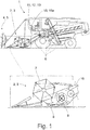
- the proposed agricultural working machine 1 which here is an example of a combine harvester, has a crop recovery arrangement 2, which is formed here by a cutting unit 3 and is arranged on the front of the agricultural working machine 1 in the direction of travel.
- the crop recovery arrangement 2 or the cutting unit 3 serves to separate and pick up crop 4 from a field stock 5, the crop 4 being fed to the agricultural machine 1 for further processing by a plurality of further working elements 6.
- the components of the crop recovery arrangement 2 here and preferably have a crop pick-up device 7 in the form of a reel, a crop cutting device 8 in the form of a cutting table with a cutter bar, a crop feed device 9 subordinate to this in terms of process technology, in the form of a screw conveyor, in particular a cross conveyor screw, and a crop feed device 10 subordinate to this in terms of process technology in the form of an inclined conveyor.
- the crop 4 is a crop flow (in Fig. 1 and 3a ) represented by arrows) through the crop recovery arrangement 2.
- the crop 4 is picked up and held by the crop pick-up device 7 or reel, while it is separated from the crop cutting device 8 becomes.
- the separated crop 4 is then moved against the here and preferably transverse crop conveying device 9 and is conveyed by the latter in the transverse direction, that is to say transversely to the direction of travel, to the center of the vehicle, where it is then drawn in by the crop collecting device 10 and conveyed further into the interior of the agricultural working machine 1 becomes.
- the agricultural working machine 1 also has a control device 11, which is used here and preferably to control the other working elements 6 of the agricultural working machine 1 in addition to the aforementioned components 7-10 of the crop recovery arrangement 2.
- the regulation can include a speed or speed regulation and / or height adjustments and / or position adjustments.
- the driving speed of the agricultural working machine 1 is controlled.
- the control device 11 here and preferably has a sensor unit 12 in the form of two cameras, the sensor unit 12 being arranged in the front area of the agricultural working machine 1 and used for the optical detection of the crop flow.
- the area of optical detection is symbolic here in the Fig. 1 and 2 shown in dashed lines.
- control device 11 has an image processing unit 13 for processing images 14, one of which is shown in FIG Fig. 3a ) is shown.
- the images 14 are generated by the sensor unit 12 based on the optically recorded crop flow.
- control device 11 has a data output unit 15, which here and preferably comprises a display device 15a and is used for outputting the images 14 processed by the image processing unit 13.
- the image processing unit 13 creates a speed map 16, also referred to as an optical flow, based on the images 14 generated by the sensor unit 12.
- the optical flow is the pixel-wise movement in the image area given by an image frequency, also referred to as a flow field.
- the frame rate is in turn defined with the pixel position and the point in time.
- the movement is a vector field in an image 14, which is made by superimposing two Images 14 of an image pair is generated, and describes the time-dependent shift of a pixel or a group of pixels, hereinafter also referred to as intensity pattern, from one to the next image of the image pair.
- the image composed of the two individual images 14 can be revised beforehand by the image processing unit 13, as shown for example in FIG EP 3 300 019 A1 is described in detail.
- the Lucas-Kanade method in which the image resolution of the images is reduced, may be mentioned here merely as an example. Furthermore, noise reduction, contrast change, brightness change or the like. be performed. The resulting image is then used to create the speed map 16.
- the image processing unit 13 is configured to create a direction change map 17 based on the images 14 generated by the sensor unit 12 in addition to the speed map 16.
- both characteristic diagrams 16, 17 are used collectively or individually by the control device 11 for regulating processes in the agricultural working machine 1, for example for regulating the work organs 6, and / or for processes in the crop movement arrangement 2, for example the components 7- 10, used.
- the image processing unit 13 creates the characteristic diagrams 16, 17, which in turn are used by the control device 11, in particular a computer unit (not shown) of the control device 11, for the control measures mentioned.
- the speed map 16 has the crop flow velocities, in particular of crop particles, and the velocities of surface sections of machine parts of the components of the crop recovery arrangement 2, here in the form of speed ranges v 1 -v 4 , in each of which several of the speeds are combined to form a range are.
- the direction change map 17 has changes in direction, in particular of crop particles, in the crop flow and / or changes in direction of surface sections of machine parts of the components 7-10 of the crop recovery arrangement 2, here in the form of change of direction ranges ⁇ 1 - ⁇ 5 , in each of which several of the changes in direction to an area are summarized.
- the image processing unit 13 groups two, in particular two immediately successive, images 14 of an image sequence generated by the sensor unit 12 into a pair of images.
- a time span between the images 14 of the respective image pair is captured by the image processing unit 13. Additionally or alternatively, a time period can be specified by the image processing unit 13.
- Each image 14 of the respective image pair has an intensity pattern, that is to say a pixel or a group of pixels.
- the image processing unit 13 uses the intensity patterns between the images 14 of the respective image pair to determine position shifts which include shift amounts and shift directions.
- the amounts of displacement and directions of displacement for each pair of images are each summarized as vectors of a vector field of the respective pair of images.
- Speeds are then calculated by the image processing unit 13 from the shift amounts of the intensity patterns between the images 14 of the respective image pair and the time span between the images 14 of the respective image pair.
- the speeds are, as previously indicated, crop flow velocities and / or velocities of surface sections of the components 7-10 of the crop recovery arrangement 2.
- the respective velocities here in the form of speed ranges v 1 -v 4 , in which several of the speeds in each case become one Area are summarized, graphically displayed by the data output unit 15, in particular by the display device 15a, here and preferably different speeds or speed ranges v 1 -v 4 are shown with different colors. Instead of different colors, different grayscale and / or textures can also be used.
- the image processing unit 13 compares directions of displacement of intensity patterns of a first image pair with directions of displacement of associated intensity patterns of a second image pair of the same image sequence, in particular of an image pair immediately following it.
- Associated intensity patterns mean that in the second image pair the same pixel or the same pixel group as in the first image pair is used.
- the changes in direction are calculated from the comparison of the directions of displacement between the two pairs of images. These are and preferably are changes in direction in the crop flow and / or of the surface sections of the machine parts.
- These changes in direction are also graphically represented by the data output unit 15 or display device 15a, here in the form of change of direction ranges ⁇ 1 - ⁇ 5 , in each of which several of the changes in direction are combined to form an area.
- different changes in direction or change in direction ⁇ 1 - ⁇ 5 are represented by different colors, with gray shades and / or textures also being used as an alternative.
- FIG. 4 An example of the representation of different speeds or speed ranges v 1 -v 4 by different colors, grayscale and / or textures is in Fig. 4 shown on the left in the middle. In the middle right there is a corresponding representation of different changes in direction or change in direction ⁇ 1 - ⁇ 5 .
- Fig. 4 schematically shows a view of the display device 15a, an image 14 of an image sequence that was generated by the sensor unit 12 being shown at the top left.
- the image 14 corresponds to the image in Fig. 3a ).
- the speed map 16 and on the right the direction change map 17 are shown.
- a definition of the colors, grayscale and / or textures for speeds or speed ranges v 1 -v 4 is shown at the bottom left and for changes in direction or changes in direction ⁇ 1 - ⁇ 5 at the bottom right.
- Fig. 4 shows the view of the display device 15a at a certain point in time. The entire image sequence is displayed over time, the speed map 16 and the direction change map 17 always adapting directly to the successive images of the image sequence.
- the control device 11 is configured here and preferably, speeds and changes in direction calculated by the image processing unit 13 to be compared with at least one predefined limit value, here in each case an upper limit value and a lower limit value. If the respective limit value is undershot, corresponding control measures of the agricultural working machine 1 and / or the crop recovery arrangement 2 are carried out, as has already been explained.
- the sensors unit 12 detects the field stock 5 both in front of the crop recovery arrangement 2 and behind it.
- the sensor unit 12 can here and preferably detect the crop receiving device 7, the crop cutting device 8, the crop conveying device 9 and the crop picking device 10. The crop flow within the crop pickup device 7 and the crop stream vertically above the crop cutting device 8, here between the crop pickup device 7 and the crop conveying device 9, are also detected.
- image areas in the images 14 are now determined, here and preferably an image area 14a with the field stock 5 in front of the crop recovery arrangement 2, an image area 14b with the field stock 5 behind the crop recovery arrangement 2, an image area 14c with the crop receiving device 7, an image area 14d with the crop cutting device 8, an image area 14e with the crop conveying device 9, an image area 14f with the crop feeding device 10, an image area 14g with the crop flow inside the crop receiving device 7 and / or an image area 14h with the crop flow vertically above the crop cutting device 8, in particular in the area between the crop receiving device 7 and the crop conveying device 9.
- the image processing unit 13 calculates the speeds and / or changes in direction, which are combined to form the speed map 16 or the direction change map 17.
- the two image areas 14g and 14h with the respective crop flow are divided here and preferably by the image processing unit 13 into sub-areas transverse to the direction of travel Fig. 4 symbolically at the top right by different Textures in the image areas 14g and 14h is shown.
- the image processing unit 13 determines an average value for the crop flow rates, which can be an absolute value, but can also be the ratio to a reference value, in particular to the upper limit value.
- the mean values can also be represented by different colors, grayscale and / or textures for visualization.
- corresponding numerical values, in particular percentage values can also be displayed (not shown here).
Landscapes
- Engineering & Computer Science (AREA)
- Multimedia (AREA)
- Physics & Mathematics (AREA)
- General Physics & Mathematics (AREA)
- Theoretical Computer Science (AREA)
- Computer Vision & Pattern Recognition (AREA)
- Life Sciences & Earth Sciences (AREA)
- Environmental Sciences (AREA)
- Mechanical Engineering (AREA)
- Signal Processing (AREA)
- Guiding Agricultural Machines (AREA)
- Management, Administration, Business Operations System, And Electronic Commerce (AREA)
- Harvesting Machines For Specific Crops (AREA)
Applications Claiming Priority (1)
| Application Number | Priority Date | Filing Date | Title |
|---|---|---|---|
| DE102018116990.6A DE102018116990A1 (de) | 2018-07-13 | 2018-07-13 | Landwirtschaftliche Arbeitsmaschine |
Publications (2)
| Publication Number | Publication Date |
|---|---|
| EP3593616A1 true EP3593616A1 (fr) | 2020-01-15 |
| EP3593616B1 EP3593616B1 (fr) | 2021-09-01 |
Family
ID=66439923
Family Applications (1)
| Application Number | Title | Priority Date | Filing Date |
|---|---|---|---|
| EP19172879.9A Active EP3593616B1 (fr) | 2018-07-13 | 2019-05-07 | Engin de travail agricole |
Country Status (3)
| Country | Link |
|---|---|
| US (1) | US11388858B2 (fr) |
| EP (1) | EP3593616B1 (fr) |
| DE (1) | DE102018116990A1 (fr) |
Cited By (1)
| Publication number | Priority date | Publication date | Assignee | Title |
|---|---|---|---|---|
| DE102022107805A1 (de) | 2022-04-01 | 2023-10-05 | Deere & Company | Maschine zur Futterernte mit vorausschauender Ansteuerung |
Families Citing this family (71)
| Publication number | Priority date | Publication date | Assignee | Title |
|---|---|---|---|---|
| JP7034866B2 (ja) * | 2018-08-20 | 2022-03-14 | 株式会社クボタ | 収穫機 |
| US12069978B2 (en) | 2018-10-26 | 2024-08-27 | Deere & Company | Predictive environmental characteristic map generation and control system |
| US11957072B2 (en) | 2020-02-06 | 2024-04-16 | Deere & Company | Pre-emergence weed detection and mitigation system |
| US11240961B2 (en) | 2018-10-26 | 2022-02-08 | Deere & Company | Controlling a harvesting machine based on a geo-spatial representation indicating where the harvesting machine is likely to reach capacity |
| US11672203B2 (en) | 2018-10-26 | 2023-06-13 | Deere & Company | Predictive map generation and control |
| US11589509B2 (en) | 2018-10-26 | 2023-02-28 | Deere & Company | Predictive machine characteristic map generation and control system |
| US11079725B2 (en) | 2019-04-10 | 2021-08-03 | Deere & Company | Machine control using real-time model |
| US11467605B2 (en) | 2019-04-10 | 2022-10-11 | Deere & Company | Zonal machine control |
| US11178818B2 (en) | 2018-10-26 | 2021-11-23 | Deere & Company | Harvesting machine control system with fill level processing based on yield data |
| US11641800B2 (en) | 2020-02-06 | 2023-05-09 | Deere & Company | Agricultural harvesting machine with pre-emergence weed detection and mitigation system |
| US11653588B2 (en) | 2018-10-26 | 2023-05-23 | Deere & Company | Yield map generation and control system |
| US10980166B2 (en) * | 2018-11-20 | 2021-04-20 | Cnh Industrial America Llc | System and method for pre-emptively adjusting machine parameters based on predicted field conditions |
| US11234366B2 (en) | 2019-04-10 | 2022-02-01 | Deere & Company | Image selection for machine control |
| US12329148B2 (en) | 2020-02-06 | 2025-06-17 | Deere & Company | Predictive weed map and material application machine control |
| US12035648B2 (en) | 2020-02-06 | 2024-07-16 | Deere & Company | Predictive weed map generation and control system |
| US12225846B2 (en) | 2020-02-06 | 2025-02-18 | Deere & Company | Machine control using a predictive map |
| US11477940B2 (en) | 2020-03-26 | 2022-10-25 | Deere & Company | Mobile work machine control based on zone parameter modification |
| US11659787B2 (en) * | 2020-04-03 | 2023-05-30 | Cnh Industrial America Llc | Harvesting head reel-crop engagement |
| US11845449B2 (en) | 2020-10-09 | 2023-12-19 | Deere & Company | Map generation and control system |
| US12422847B2 (en) | 2020-10-09 | 2025-09-23 | Deere & Company | Predictive agricultural model and map generation |
| US11727680B2 (en) | 2020-10-09 | 2023-08-15 | Deere & Company | Predictive map generation based on seeding characteristics and control |
| US11844311B2 (en) | 2020-10-09 | 2023-12-19 | Deere & Company | Machine control using a predictive map |
| US11650587B2 (en) | 2020-10-09 | 2023-05-16 | Deere & Company | Predictive power map generation and control system |
| US11927459B2 (en) | 2020-10-09 | 2024-03-12 | Deere & Company | Machine control using a predictive map |
| US11635765B2 (en) | 2020-10-09 | 2023-04-25 | Deere & Company | Crop state map generation and control system |
| US12013245B2 (en) | 2020-10-09 | 2024-06-18 | Deere & Company | Predictive map generation and control system |
| US11895948B2 (en) | 2020-10-09 | 2024-02-13 | Deere & Company | Predictive map generation and control based on soil properties |
| US11592822B2 (en) | 2020-10-09 | 2023-02-28 | Deere & Company | Machine control using a predictive map |
| US11946747B2 (en) | 2020-10-09 | 2024-04-02 | Deere & Company | Crop constituent map generation and control system |
| US11825768B2 (en) | 2020-10-09 | 2023-11-28 | Deere & Company | Machine control using a predictive map |
| US11983009B2 (en) | 2020-10-09 | 2024-05-14 | Deere & Company | Map generation and control system |
| US11474523B2 (en) | 2020-10-09 | 2022-10-18 | Deere & Company | Machine control using a predictive speed map |
| US12419220B2 (en) | 2020-10-09 | 2025-09-23 | Deere & Company | Predictive map generation and control system |
| US20220110238A1 (en) | 2020-10-09 | 2022-04-14 | Deere & Company | Machine control using a predictive map |
| US11871697B2 (en) | 2020-10-09 | 2024-01-16 | Deere & Company | Crop moisture map generation and control system |
| US12069986B2 (en) | 2020-10-09 | 2024-08-27 | Deere & Company | Map generation and control system |
| US11675354B2 (en) | 2020-10-09 | 2023-06-13 | Deere & Company | Machine control using a predictive map |
| US11864483B2 (en) | 2020-10-09 | 2024-01-09 | Deere & Company | Predictive map generation and control system |
| US11849672B2 (en) | 2020-10-09 | 2023-12-26 | Deere & Company | Machine control using a predictive map |
| US11874669B2 (en) | 2020-10-09 | 2024-01-16 | Deere & Company | Map generation and control system |
| US11711995B2 (en) | 2020-10-09 | 2023-08-01 | Deere & Company | Machine control using a predictive map |
| US11849671B2 (en) | 2020-10-09 | 2023-12-26 | Deere & Company | Crop state map generation and control system |
| US12386354B2 (en) | 2020-10-09 | 2025-08-12 | Deere & Company | Predictive power map generation and control system |
| US20220110258A1 (en) | 2020-10-09 | 2022-04-14 | Deere & Company | Map generation and control system |
| US12178158B2 (en) | 2020-10-09 | 2024-12-31 | Deere & Company | Predictive map generation and control system for an agricultural work machine |
| US12550802B2 (en) | 2020-10-08 | 2026-02-17 | Deere & Company | Predictive machine characteristic map generation and control system |
| US11889788B2 (en) | 2020-10-09 | 2024-02-06 | Deere & Company | Predictive biomass map generation and control |
| US12250905B2 (en) | 2020-10-09 | 2025-03-18 | Deere & Company | Machine control using a predictive map |
| US11889787B2 (en) | 2020-10-09 | 2024-02-06 | Deere & Company | Predictive speed map generation and control system |
| US12127500B2 (en) | 2021-01-27 | 2024-10-29 | Deere & Company | Machine control using a map with regime zones |
| CN113607168B (zh) * | 2021-06-15 | 2023-06-20 | 成都农业科技职业学院 | 扦插机器视觉定位装置及方法 |
| US12229886B2 (en) | 2021-10-01 | 2025-02-18 | Deere & Company | Historical crop state model, predictive crop state map generation and control system |
| US12310286B2 (en) | 2021-12-14 | 2025-05-27 | Deere & Company | Crop constituent sensing |
| US12302791B2 (en) | 2021-12-20 | 2025-05-20 | Deere & Company | Crop constituents, predictive mapping, and agricultural harvester control |
| US12245549B2 (en) | 2022-01-11 | 2025-03-11 | Deere & Company | Predictive response map generation and control system |
| US12520759B2 (en) | 2022-01-26 | 2026-01-13 | Deere & Company | Systems and methods for predicting material dynamics |
| US12082531B2 (en) | 2022-01-26 | 2024-09-10 | Deere & Company | Systems and methods for predicting material dynamics |
| US12295288B2 (en) | 2022-04-05 | 2025-05-13 | Deere &Company | Predictive machine setting map generation and control system |
| US12358493B2 (en) | 2022-04-08 | 2025-07-15 | Deere & Company | Systems and methods for predictive power requirements and control |
| US12582035B2 (en) | 2022-04-08 | 2026-03-24 | Deere & Company | Systems and methods for predictive power requirements and control |
| US12298767B2 (en) | 2022-04-08 | 2025-05-13 | Deere & Company | Predictive material consumption map and control |
| US12058951B2 (en) | 2022-04-08 | 2024-08-13 | Deere & Company | Predictive nutrient map and control |
| US12284934B2 (en) | 2022-04-08 | 2025-04-29 | Deere & Company | Systems and methods for predictive tractive characteristics and control |
| US12408592B2 (en) * | 2022-06-10 | 2025-09-09 | Cnh Industrial America Llc | Agricultural baler system with bale stall identification |
| EP4331342B1 (fr) * | 2022-08-26 | 2026-04-08 | CLAAS Selbstfahrende Erntemaschinen GmbH | Machine de travail agricole dotée d'un système d'aide à la conduite |
| DE102022128699A1 (de) | 2022-10-28 | 2024-05-08 | Claas Selbstfahrende Erntemaschinen Gmbh | Landwirtschaftliche Arbeitsmaschine |
| US12310285B2 (en) * | 2023-02-27 | 2025-05-27 | Deere & Company | Agricultural operation evaluation system and method |
| US12568881B2 (en) | 2023-03-07 | 2026-03-10 | Deere & Company | Measuring loss and calibrating loss sensors on an agricultural harvester |
| USD1083987S1 (en) | 2023-09-20 | 2025-07-15 | Deere & Company | Display screen or portion thereof with graphical user interface |
| USD1082823S1 (en) | 2023-09-20 | 2025-07-08 | Deere & Company | Display screen or portion thereof with graphical user interface |
| USD1084021S1 (en) | 2023-09-20 | 2025-07-15 | Deere &Company | Display screen or portion thereof with graphical user interface |
Citations (3)
| Publication number | Priority date | Publication date | Assignee | Title |
|---|---|---|---|---|
| EP2143316A1 (fr) * | 2008-07-09 | 2010-01-13 | CLAAS Selbstfahrende Erntemaschinen | Moissonneuse automobile |
| EP3150047A1 (fr) * | 2015-09-30 | 2017-04-05 | CLAAS Selbstfahrende Erntemaschinen GmbH | Procede de reconnaissance de pannes d'un systeme de sauvetage de recolte |
| EP3300019A1 (fr) | 2016-09-27 | 2018-03-28 | CLAAS Selbstfahrende Erntemaschinen GmbH | Surveillance d'écoulement de produit dans un dispositif de collecte de récolte |
Family Cites Families (5)
| Publication number | Priority date | Publication date | Assignee | Title |
|---|---|---|---|---|
| GB9811177D0 (en) * | 1998-05-26 | 1998-07-22 | Ford New Holland Nv | Methods for generating field maps |
| DE10129135B4 (de) * | 2001-06-16 | 2013-10-24 | Deere & Company | Einrichtung zur Positionsbestimmung eines landwirtschaftlichen Arbeitsfahrzeugs sowie ein landwirtschaftliches Arbeitsfahrzeug mit dieser |
| BE1021107B1 (nl) * | 2013-10-28 | 2016-01-18 | Cnh Industrial Belgium Nv | Zwadsensor voor veldhakselaar |
| BE1022889B1 (nl) * | 2015-05-29 | 2016-10-07 | Cnh Industrial Belgium Nv | controller voor een oogstmachine |
| DE102017204433A1 (de) * | 2017-03-16 | 2018-09-20 | Zf Friedrichshafen Ag | Verfahren zum Betreiben eines Systems aus einem landwirtschaftlichen Arbeitsfahrzeug und zumindest einem an diesem angeordneten Arbeitsgerät |
-
2018
- 2018-07-13 DE DE102018116990.6A patent/DE102018116990A1/de not_active Withdrawn
-
2019
- 2019-05-07 EP EP19172879.9A patent/EP3593616B1/fr active Active
- 2019-06-13 US US16/440,036 patent/US11388858B2/en active Active
Patent Citations (3)
| Publication number | Priority date | Publication date | Assignee | Title |
|---|---|---|---|---|
| EP2143316A1 (fr) * | 2008-07-09 | 2010-01-13 | CLAAS Selbstfahrende Erntemaschinen | Moissonneuse automobile |
| EP3150047A1 (fr) * | 2015-09-30 | 2017-04-05 | CLAAS Selbstfahrende Erntemaschinen GmbH | Procede de reconnaissance de pannes d'un systeme de sauvetage de recolte |
| EP3300019A1 (fr) | 2016-09-27 | 2018-03-28 | CLAAS Selbstfahrende Erntemaschinen GmbH | Surveillance d'écoulement de produit dans un dispositif de collecte de récolte |
Cited By (1)
| Publication number | Priority date | Publication date | Assignee | Title |
|---|---|---|---|---|
| DE102022107805A1 (de) | 2022-04-01 | 2023-10-05 | Deere & Company | Maschine zur Futterernte mit vorausschauender Ansteuerung |
Also Published As
| Publication number | Publication date |
|---|---|
| US20200015416A1 (en) | 2020-01-16 |
| EP3593616B1 (fr) | 2021-09-01 |
| RU2019120759A (ru) | 2021-01-11 |
| DE102018116990A1 (de) | 2020-01-16 |
| US11388858B2 (en) | 2022-07-19 |
Similar Documents
| Publication | Publication Date | Title |
|---|---|---|
| EP3593616B1 (fr) | Engin de travail agricole | |
| EP3616496B1 (fr) | Engin de travail agricole | |
| EP3300019B1 (fr) | Surveillance d'écoulement de produit dans un dispositif de collecte de récolte | |
| EP3578032B1 (fr) | Procédé de commande d'une campagne de récolte agricole | |
| EP3400774B1 (fr) | Procédé d'élaboration d'un processus de récolte agricole | |
| EP3766329B1 (fr) | Engin d'abattage-façonnage agricole | |
| EP2220925B1 (fr) | Véhicule de travail agricole et unité d'affichage correspondante | |
| EP2183954B1 (fr) | Etablissement de banques de données d'images pour une évaluation d'image | |
| EP4155839A1 (fr) | Machine de travail agricole dotée d'au moins un dispositif de commande | |
| EP2570968A2 (fr) | Procédé et agencement pour l'évaluation optique de produits agricoles dans une moissonneuse | |
| DE102018127846A1 (de) | Verfahren zur Regelung des Betriebs einer Maschine zum Ernten von Hackfrüchten | |
| EP2728523A1 (fr) | Système d'assistance pour l'optimisation du fonctionnement d'un véhicule | |
| DE102018127844A1 (de) | Verfahren zur Regelung des Betriebs einer Maschine zum Ernten von Hackfrüchten | |
| EP2110012B1 (fr) | Procédé et dispositif d'optimisation de paramètres de fonctionnement d'une machine de travail agricole | |
| EP3150047A1 (fr) | Procede de reconnaissance de pannes d'un systeme de sauvetage de recolte | |
| WO2023021005A1 (fr) | Procédé d'évaluation d'image d'un paramètre de fonctionnement d'un outil frontal de récolte agricole | |
| EP3785516A1 (fr) | Dispositif de détermination permettant de déterminer une date de cueillette de fruits, dispositif de traitement correspondant et machine de cueillette | |
| EP3791704B1 (fr) | Procédé de commande du fonctionnement d'un outil de travail | |
| EP3653052A1 (fr) | Procédé de détection de la distance d'une tige par rapport à une surface agricole et à sa végétation | |
| DE102019214486B4 (de) | Erntevorsatzüberwachung anhand von Erntemengenabweichungen | |
| EP3622799A1 (fr) | Procédé de fonctionnement d'un engin d'abattage-façonnage automoteur | |
| EP4295656A1 (fr) | Procédé de configuration optimisée d'un système de caméra pour la détection de rangée dans un actif de terrain | |
| BE1026709B1 (de) | Verfahren zur Regelung des Betriebs einer Maschine zum Ernten von Hackfrüchten | |
| EP3732950B1 (fr) | Procédé de fonctionnement d'un engin agricole automatique | |
| DE102022128699A1 (de) | Landwirtschaftliche Arbeitsmaschine |
Legal Events
| Date | Code | Title | Description |
|---|---|---|---|
| PUAI | Public reference made under article 153(3) epc to a published international application that has entered the european phase |
Free format text: ORIGINAL CODE: 0009012 |
|
| STAA | Information on the status of an ep patent application or granted ep patent |
Free format text: STATUS: THE APPLICATION HAS BEEN PUBLISHED |
|
| AK | Designated contracting states |
Kind code of ref document: A1 Designated state(s): AL AT BE BG CH CY CZ DE DK EE ES FI FR GB GR HR HU IE IS IT LI LT LU LV MC MK MT NL NO PL PT RO RS SE SI SK SM TR |
|
| AX | Request for extension of the european patent |
Extension state: BA ME |
|
| STAA | Information on the status of an ep patent application or granted ep patent |
Free format text: STATUS: REQUEST FOR EXAMINATION WAS MADE |
|
| 17P | Request for examination filed |
Effective date: 20200715 |
|
| RBV | Designated contracting states (corrected) |
Designated state(s): AL AT BE BG CH CY CZ DE DK EE ES FI FR GB GR HR HU IE IS IT LI LT LU LV MC MK MT NL NO PL PT RO RS SE SI SK SM TR |
|
| GRAP | Despatch of communication of intention to grant a patent |
Free format text: ORIGINAL CODE: EPIDOSNIGR1 |
|
| STAA | Information on the status of an ep patent application or granted ep patent |
Free format text: STATUS: GRANT OF PATENT IS INTENDED |
|
| INTG | Intention to grant announced |
Effective date: 20210514 |
|
| GRAS | Grant fee paid |
Free format text: ORIGINAL CODE: EPIDOSNIGR3 |
|
| GRAA | (expected) grant |
Free format text: ORIGINAL CODE: 0009210 |
|
| STAA | Information on the status of an ep patent application or granted ep patent |
Free format text: STATUS: THE PATENT HAS BEEN GRANTED |
|
| AK | Designated contracting states |
Kind code of ref document: B1 Designated state(s): AL AT BE BG CH CY CZ DE DK EE ES FI FR GB GR HR HU IE IS IT LI LT LU LV MC MK MT NL NO PL PT RO RS SE SI SK SM TR |
|
| REG | Reference to a national code |
Ref country code: GB Ref legal event code: FG4D Free format text: NOT ENGLISH |
|
| REG | Reference to a national code |
Ref country code: CH Ref legal event code: EP Ref country code: AT Ref legal event code: REF Ref document number: 1425192 Country of ref document: AT Kind code of ref document: T Effective date: 20210915 |
|
| REG | Reference to a national code |
Ref country code: DE Ref legal event code: R096 Ref document number: 502019002172 Country of ref document: DE |
|
| REG | Reference to a national code |
Ref country code: IE Ref legal event code: FG4D Free format text: LANGUAGE OF EP DOCUMENT: GERMAN |
|
| REG | Reference to a national code |
Ref country code: LT Ref legal event code: MG9D |
|
| REG | Reference to a national code |
Ref country code: NL Ref legal event code: MP Effective date: 20210901 |
|
| PG25 | Lapsed in a contracting state [announced via postgrant information from national office to epo] |
Ref country code: BG Free format text: LAPSE BECAUSE OF FAILURE TO SUBMIT A TRANSLATION OF THE DESCRIPTION OR TO PAY THE FEE WITHIN THE PRESCRIBED TIME-LIMIT Effective date: 20211201 Ref country code: LT Free format text: LAPSE BECAUSE OF FAILURE TO SUBMIT A TRANSLATION OF THE DESCRIPTION OR TO PAY THE FEE WITHIN THE PRESCRIBED TIME-LIMIT Effective date: 20210901 Ref country code: NO Free format text: LAPSE BECAUSE OF FAILURE TO SUBMIT A TRANSLATION OF THE DESCRIPTION OR TO PAY THE FEE WITHIN THE PRESCRIBED TIME-LIMIT Effective date: 20211201 Ref country code: HR Free format text: LAPSE BECAUSE OF FAILURE TO SUBMIT A TRANSLATION OF THE DESCRIPTION OR TO PAY THE FEE WITHIN THE PRESCRIBED TIME-LIMIT Effective date: 20210901 Ref country code: RS Free format text: LAPSE BECAUSE OF FAILURE TO SUBMIT A TRANSLATION OF THE DESCRIPTION OR TO PAY THE FEE WITHIN THE PRESCRIBED TIME-LIMIT Effective date: 20210901 Ref country code: SE Free format text: LAPSE BECAUSE OF FAILURE TO SUBMIT A TRANSLATION OF THE DESCRIPTION OR TO PAY THE FEE WITHIN THE PRESCRIBED TIME-LIMIT Effective date: 20210901 Ref country code: FI Free format text: LAPSE BECAUSE OF FAILURE TO SUBMIT A TRANSLATION OF THE DESCRIPTION OR TO PAY THE FEE WITHIN THE PRESCRIBED TIME-LIMIT Effective date: 20210901 Ref country code: ES Free format text: LAPSE BECAUSE OF FAILURE TO SUBMIT A TRANSLATION OF THE DESCRIPTION OR TO PAY THE FEE WITHIN THE PRESCRIBED TIME-LIMIT Effective date: 20210901 |
|
| PG25 | Lapsed in a contracting state [announced via postgrant information from national office to epo] |
Ref country code: PL Free format text: LAPSE BECAUSE OF FAILURE TO SUBMIT A TRANSLATION OF THE DESCRIPTION OR TO PAY THE FEE WITHIN THE PRESCRIBED TIME-LIMIT Effective date: 20210901 Ref country code: LV Free format text: LAPSE BECAUSE OF FAILURE TO SUBMIT A TRANSLATION OF THE DESCRIPTION OR TO PAY THE FEE WITHIN THE PRESCRIBED TIME-LIMIT Effective date: 20210901 Ref country code: GR Free format text: LAPSE BECAUSE OF FAILURE TO SUBMIT A TRANSLATION OF THE DESCRIPTION OR TO PAY THE FEE WITHIN THE PRESCRIBED TIME-LIMIT Effective date: 20211202 |
|
| PG25 | Lapsed in a contracting state [announced via postgrant information from national office to epo] |
Ref country code: IS Free format text: LAPSE BECAUSE OF FAILURE TO SUBMIT A TRANSLATION OF THE DESCRIPTION OR TO PAY THE FEE WITHIN THE PRESCRIBED TIME-LIMIT Effective date: 20220101 Ref country code: SM Free format text: LAPSE BECAUSE OF FAILURE TO SUBMIT A TRANSLATION OF THE DESCRIPTION OR TO PAY THE FEE WITHIN THE PRESCRIBED TIME-LIMIT Effective date: 20210901 Ref country code: SK Free format text: LAPSE BECAUSE OF FAILURE TO SUBMIT A TRANSLATION OF THE DESCRIPTION OR TO PAY THE FEE WITHIN THE PRESCRIBED TIME-LIMIT Effective date: 20210901 Ref country code: RO Free format text: LAPSE BECAUSE OF FAILURE TO SUBMIT A TRANSLATION OF THE DESCRIPTION OR TO PAY THE FEE WITHIN THE PRESCRIBED TIME-LIMIT Effective date: 20210901 Ref country code: PT Free format text: LAPSE BECAUSE OF FAILURE TO SUBMIT A TRANSLATION OF THE DESCRIPTION OR TO PAY THE FEE WITHIN THE PRESCRIBED TIME-LIMIT Effective date: 20220103 Ref country code: NL Free format text: LAPSE BECAUSE OF FAILURE TO SUBMIT A TRANSLATION OF THE DESCRIPTION OR TO PAY THE FEE WITHIN THE PRESCRIBED TIME-LIMIT Effective date: 20210901 Ref country code: EE Free format text: LAPSE BECAUSE OF FAILURE TO SUBMIT A TRANSLATION OF THE DESCRIPTION OR TO PAY THE FEE WITHIN THE PRESCRIBED TIME-LIMIT Effective date: 20210901 Ref country code: CZ Free format text: LAPSE BECAUSE OF FAILURE TO SUBMIT A TRANSLATION OF THE DESCRIPTION OR TO PAY THE FEE WITHIN THE PRESCRIBED TIME-LIMIT Effective date: 20210901 Ref country code: AL Free format text: LAPSE BECAUSE OF FAILURE TO SUBMIT A TRANSLATION OF THE DESCRIPTION OR TO PAY THE FEE WITHIN THE PRESCRIBED TIME-LIMIT Effective date: 20210901 |
|
| REG | Reference to a national code |
Ref country code: DE Ref legal event code: R097 Ref document number: 502019002172 Country of ref document: DE |
|
| PLBE | No opposition filed within time limit |
Free format text: ORIGINAL CODE: 0009261 |
|
| STAA | Information on the status of an ep patent application or granted ep patent |
Free format text: STATUS: NO OPPOSITION FILED WITHIN TIME LIMIT |
|
| PG25 | Lapsed in a contracting state [announced via postgrant information from national office to epo] |
Ref country code: IT Free format text: LAPSE BECAUSE OF FAILURE TO SUBMIT A TRANSLATION OF THE DESCRIPTION OR TO PAY THE FEE WITHIN THE PRESCRIBED TIME-LIMIT Effective date: 20210901 Ref country code: DK Free format text: LAPSE BECAUSE OF FAILURE TO SUBMIT A TRANSLATION OF THE DESCRIPTION OR TO PAY THE FEE WITHIN THE PRESCRIBED TIME-LIMIT Effective date: 20210901 |
|
| 26N | No opposition filed |
Effective date: 20220602 |
|
| PG25 | Lapsed in a contracting state [announced via postgrant information from national office to epo] |
Ref country code: SI Free format text: LAPSE BECAUSE OF FAILURE TO SUBMIT A TRANSLATION OF THE DESCRIPTION OR TO PAY THE FEE WITHIN THE PRESCRIBED TIME-LIMIT Effective date: 20210901 |
|
| REG | Reference to a national code |
Ref country code: CH Ref legal event code: PL |
|
| PG25 | Lapsed in a contracting state [announced via postgrant information from national office to epo] |
Ref country code: MC Free format text: LAPSE BECAUSE OF FAILURE TO SUBMIT A TRANSLATION OF THE DESCRIPTION OR TO PAY THE FEE WITHIN THE PRESCRIBED TIME-LIMIT Effective date: 20210901 Ref country code: LU Free format text: LAPSE BECAUSE OF NON-PAYMENT OF DUE FEES Effective date: 20220507 Ref country code: LI Free format text: LAPSE BECAUSE OF NON-PAYMENT OF DUE FEES Effective date: 20220531 Ref country code: CH Free format text: LAPSE BECAUSE OF NON-PAYMENT OF DUE FEES Effective date: 20220531 |
|
| PG25 | Lapsed in a contracting state [announced via postgrant information from national office to epo] |
Ref country code: IE Free format text: LAPSE BECAUSE OF NON-PAYMENT OF DUE FEES Effective date: 20220507 |
|
| P01 | Opt-out of the competence of the unified patent court (upc) registered |
Effective date: 20230516 |
|
| GBPC | Gb: european patent ceased through non-payment of renewal fee |
Effective date: 20230507 |
|
| PG25 | Lapsed in a contracting state [announced via postgrant information from national office to epo] |
Ref country code: MK Free format text: LAPSE BECAUSE OF FAILURE TO SUBMIT A TRANSLATION OF THE DESCRIPTION OR TO PAY THE FEE WITHIN THE PRESCRIBED TIME-LIMIT Effective date: 20210901 Ref country code: CY Free format text: LAPSE BECAUSE OF FAILURE TO SUBMIT A TRANSLATION OF THE DESCRIPTION OR TO PAY THE FEE WITHIN THE PRESCRIBED TIME-LIMIT Effective date: 20210901 Ref country code: GB Free format text: LAPSE BECAUSE OF NON-PAYMENT OF DUE FEES Effective date: 20230507 |
|
| PG25 | Lapsed in a contracting state [announced via postgrant information from national office to epo] |
Ref country code: HU Free format text: LAPSE BECAUSE OF FAILURE TO SUBMIT A TRANSLATION OF THE DESCRIPTION OR TO PAY THE FEE WITHIN THE PRESCRIBED TIME-LIMIT; INVALID AB INITIO Effective date: 20190507 |
|
| PG25 | Lapsed in a contracting state [announced via postgrant information from national office to epo] |
Ref country code: MT Free format text: LAPSE BECAUSE OF FAILURE TO SUBMIT A TRANSLATION OF THE DESCRIPTION OR TO PAY THE FEE WITHIN THE PRESCRIBED TIME-LIMIT Effective date: 20210901 |
|
| PGFP | Annual fee paid to national office [announced via postgrant information from national office to epo] |
Ref country code: DE Payment date: 20250521 Year of fee payment: 7 |
|
| PGFP | Annual fee paid to national office [announced via postgrant information from national office to epo] |
Ref country code: BE Payment date: 20250521 Year of fee payment: 7 |
|
| REG | Reference to a national code |
Ref country code: AT Ref legal event code: MM01 Ref document number: 1425192 Country of ref document: AT Kind code of ref document: T Effective date: 20240507 |
|
| PGFP | Annual fee paid to national office [announced via postgrant information from national office to epo] |
Ref country code: FR Payment date: 20250528 Year of fee payment: 7 |
|
| PG25 | Lapsed in a contracting state [announced via postgrant information from national office to epo] |
Ref country code: AT Free format text: LAPSE BECAUSE OF NON-PAYMENT OF DUE FEES Effective date: 20240507 |
|
| PG25 | Lapsed in a contracting state [announced via postgrant information from national office to epo] |
Ref country code: TR Free format text: LAPSE BECAUSE OF FAILURE TO SUBMIT A TRANSLATION OF THE DESCRIPTION OR TO PAY THE FEE WITHIN THE PRESCRIBED TIME-LIMIT Effective date: 20210901 |
|
| PGFP | Annual fee paid to national office [announced via postgrant information from national office to epo] |
Ref country code: AT Payment date: 20260410 Year of fee payment: 5 |