EP3598848A1 - Dispositif de chauffage pour une table de cuisson et table de cuisson - Google Patents
Dispositif de chauffage pour une table de cuisson et table de cuisson Download PDFInfo
- Publication number
- EP3598848A1 EP3598848A1 EP19185136.9A EP19185136A EP3598848A1 EP 3598848 A1 EP3598848 A1 EP 3598848A1 EP 19185136 A EP19185136 A EP 19185136A EP 3598848 A1 EP3598848 A1 EP 3598848A1
- Authority
- EP
- European Patent Office
- Prior art keywords
- heating
- partial
- carrier
- partial heating
- hob
- Prior art date
- Legal status (The legal status is an assumption and is not a legal conclusion. Google has not performed a legal analysis and makes no representation as to the accuracy of the status listed.)
- Granted
Links
Images


Classifications
-
- H—ELECTRICITY
- H05—ELECTRIC TECHNIQUES NOT OTHERWISE PROVIDED FOR
- H05B—ELECTRIC HEATING; ELECTRIC LIGHT SOURCES NOT OTHERWISE PROVIDED FOR; CIRCUIT ARRANGEMENTS FOR ELECTRIC LIGHT SOURCES, IN GENERAL
- H05B3/00—Ohmic-resistance heating
- H05B3/68—Heating arrangements specially adapted for cooking plates or analogous hot-plates
- H05B3/74—Non-metallic plates, e.g. vitroceramic, ceramic or glassceramic hobs, also including power or control circuits
- H05B3/748—Resistive heating elements, i.e. heating elements exposed to the air, e.g. coil wire heater
-
- F—MECHANICAL ENGINEERING; LIGHTING; HEATING; WEAPONS; BLASTING
- F24—HEATING; RANGES; VENTILATING
- F24C—DOMESTIC STOVES OR RANGES ; DETAILS OF DOMESTIC STOVES OR RANGES, OF GENERAL APPLICATION
- F24C7/00—Stoves or ranges heated by electric energy
- F24C7/08—Arrangement or mounting of control or safety devices
- F24C7/082—Arrangement or mounting of control or safety devices on ranges, e.g. control panels, illumination
- F24C7/083—Arrangement or mounting of control or safety devices on ranges, e.g. control panels, illumination on tops, hot plates
-
- F—MECHANICAL ENGINEERING; LIGHTING; HEATING; WEAPONS; BLASTING
- F24—HEATING; RANGES; VENTILATING
- F24C—DOMESTIC STOVES OR RANGES ; DETAILS OF DOMESTIC STOVES OR RANGES, OF GENERAL APPLICATION
- F24C7/00—Stoves or ranges heated by electric energy
- F24C7/04—Stoves or ranges heated by electric energy with heat radiated directly from the heating element
- F24C7/046—Ranges
-
- F—MECHANICAL ENGINEERING; LIGHTING; HEATING; WEAPONS; BLASTING
- F24—HEATING; RANGES; VENTILATING
- F24C—DOMESTIC STOVES OR RANGES ; DETAILS OF DOMESTIC STOVES OR RANGES, OF GENERAL APPLICATION
- F24C7/00—Stoves or ranges heated by electric energy
- F24C7/06—Arrangement or mounting of electric heating elements
- F24C7/067—Arrangement or mounting of electric heating elements on ranges
-
- H—ELECTRICITY
- H05—ELECTRIC TECHNIQUES NOT OTHERWISE PROVIDED FOR
- H05B—ELECTRIC HEATING; ELECTRIC LIGHT SOURCES NOT OTHERWISE PROVIDED FOR; CIRCUIT ARRANGEMENTS FOR ELECTRIC LIGHT SOURCES, IN GENERAL
- H05B2206/00—Aspects relating to heating by electric, magnetic, or electromagnetic fields covered by group H05B6/00
- H05B2206/02—Induction heating
- H05B2206/022—Special supports for the induction coils
-
- H—ELECTRICITY
- H05—ELECTRIC TECHNIQUES NOT OTHERWISE PROVIDED FOR
- H05B—ELECTRIC HEATING; ELECTRIC LIGHT SOURCES NOT OTHERWISE PROVIDED FOR; CIRCUIT ARRANGEMENTS FOR ELECTRIC LIGHT SOURCES, IN GENERAL
- H05B2213/00—Aspects relating both to resistive heating and to induction heating, covered by H05B3/00 and H05B6/00
- H05B2213/03—Heating plates made out of a matrix of heating elements that can define heating areas adapted to cookware randomly placed on the heating plate
Definitions
- the invention relates to a heating device for a hob and a hob with several such heating devices.
- Radiant heaters are a well-known and very well-proven technology for heaters. Such heaters are for example from the DE 3613902 A1 known in detail.
- a hob on which heating elements are arranged, advantageously two heating elements, each with a heating conductor.
- the heating conductors run here in an interlocking, angular-spiral manner within a jointly formed heating surface which is delimited by a circumferential, upstanding outer edge of the carrier.
- Several of these heating devices for example four heating devices, can be arranged relatively close to one another in the hob in order to achieve as complete a heating as possible or to make the best possible use of the surface of the hob.
- the invention has for its object to provide a heating device mentioned above and a hob provided with such heating devices with which problems of the prior art can be solved and in particular it is possible to realize advantageous types of heating with different sized cooking vessels on the hob.
- the heating device has a flat carrier with an outer edge.
- This flat carrier can advantageously be flat, but it does not have to be.
- the outer edge can also be raised, but this is also not mandatory. In any case, the outer edge limits the wearer to the outside.
- the carrier has a substantially rectangular shape Shape, especially with slightly rounded or beveled corners. Opposing sides in parallel to each other are advantageous.
- the heating device has at least two heating elements, advantageously arranged or fastened on the carrier.
- the heating elements each have at least one heating conductor and together form a heating surface which advantageously corresponds approximately to the surface of the carrier.
- a heating element could also have two heating conductors. Heating elements or heating conductors advantageously generate upward radiant heat during operation.
- a heating conductor is advantageously defined in that it has two ends and can be electrically connected or contacted to it for its operation. Furthermore, it is provided that the heating elements and / or the partial heating surfaces can be operated or operated independently of one another. For this purpose, they can each have their own electrical connections or can be electrically contacted separately from one another. Some connections of several heating elements or partial heating surfaces can also be provided together, as is known per se for such heating devices and in particular radiant heating devices.
- the heating conductors are attached to the carrier, possibly with partial embedding in an upper side of the carrier.
- Each heating element defines a partial heating surface, advantageously exactly a single partial heating surface.
- the heating device has at least two partial heating surfaces, advantageously exactly two partial heating surfaces. These partial heating surfaces lie within the rectangular shape of the carrier, namely within the outer edge.
- a partial heating surface of a heating device do not overlap, that is to say they run separately from one another. It can be provided that a partial area is everywhere where a heating conductor of the associated heating element runs, that is to say it is defined in terms of area by it. It is therefore advantageously also provided that no heating conductors overlap or cross. Furthermore, a first partial heating surface is rectangular. It extends with at least one of its outer sides to the outer edge of the carrier or to an inner side of this outer edge when it is pulled upwards, as has been described above. This at least one outside of the partial heating surface also runs parallel to this outer edge, to which it extends directly or close to it.
- the heating device has a second partial heating surface corresponding to a second heating element.
- This second partial heating surface covers the remaining carrier, which is left free from the first partial heating surface.
- the second partial heating surface of more than one heating element or more than one single heating conductor is formed, so that it can also be viewed as the sum of several further partial heating surfaces or is formed from several further partial heating surfaces.
- the first partial heating surface is rectangular.
- the area of the carrier which is still left free from the first partial heating surface is also covered by at least one heating element or at least one heating conductor and thus also heats.
- a heating device with a carrier which has at least one separately operable rectangular partial heating surface which lies on the edge of the carrier. It can therefore be operated very well with other partial heating surfaces of a further heating device, which is arranged close to it, as a so-called bridge or bridged heating device for heating suitable cooking vessels, for example elongated oval cookers.
- the heating elements or the heating conductors are resistance heating elements and are designed to glow during operation or even to glow somewhat. They heat the cooking vessels placed above them using their radiant heating power. This is also from the above DE 3613902 A1 known.
- the first partial heating surface with two of its outer sides which advantageously abut one another or form a corner with one another, each extend to the outer edge or to an inner side of the outer edge of the carrier. They also run parallel to it.
- the first partial heating surface can thus preferably be located in a corner or in a corner region of the carrier, so to speak. Then it can not only be operated together with a single further partial heating surface of an adjacent heating device as the aforementioned bridge or bridged heating device, but also or alternatively with yet another partial heating surface of a further heating device.
- a cooktop according to the invention can be provided in a cooktop according to the invention that not only at least two heating devices according to the invention are arranged next to one another in such a way that they are close together.
- This can in particular be a distance of less than 2 cm, so that the respective first partial heating surfaces of the two heating devices are adjacent and parallel to one another with their outer sides.
- Four such heating devices can even be arranged in the square, and in the center, where four corners meet, four partial heating surfaces can also meet. Their corners are then only a short distance apart, advantageously less than 2 cm to 4 cm.
- the first partial heating surface has a square shape.
- an outside of the first partial heating surface can have a length between 100 mm and 200 mm, preferably between 110 mm and 150 mm. This results in a customary size for customary cooking vessel sizes, in particular even if two of them are to be used to heat an elongated oval roaster mentioned at the beginning.
- Frequently used cooking vessels with a diameter of 150 mm have an inner square with an edge length of almost 110 mm.
- the aforementioned roasters often have a length between 250 mm and 400 mm along their larger longitudinal extent.
- a square shape of the above size fits well.
- the second partial heating surface preferably has an L shape, so that the first partial heating surface lies in the inner angle formed thereby.
- the first partial heating surface and the second partial heating surface jointly form a rectangular or square surface, specifically covering the flat carrier up to its outer edge or to the inside thereof.
- the second partial heating surface can in turn also be formed by a plurality of heating elements or heating conductors which can be operated separately.
- the second partial heating surface can preferably have legs of approximately the same width, which, however, can be of different lengths. The length difference can be a factor of 1.2 to 2.5, advantageously 1.5 to 2.
- a small rectangular area corresponding to the first partial heating area can be heated separately, as a rule for a relatively small cooking vessel.
- Operating the second partial heating surface alone will generally not make any sense, since no correspondingly shaped cooking vessels are common.
- a possible next larger area to be heated for a cooking vessel is advantageously the joint operation of the first partial heating area and the second partial heating area, and thus the entire heating device. This can be suitable for medium-sized cooking vessels.
- two adjacent first partial heating surfaces can be heated as explained above.
- two adjacent heating devices can be operated completely, i.e. their first and second partial heating surfaces.
- the carrier itself it even has a special square shape.
- the first partial heating surface is also almost square or has a difference in its side lengths of a maximum of 10%.
- at least one heating device according to the invention is square and at least one heating device according to the invention is rectangular. In some cases, they can be arranged close to one another or next to one another in order to enable heating of different or variable surfaces in combination.
- an elongated temperature sensor or temperature limiter can be provided on the heating device, which runs above the heating elements or the heating conductor.
- a temperature sensor or temperature limiter runs at least over the first partial heating surface, possibly also over the second partial heating surface. Since with such a heating device, as has been explained at the beginning, the first partial heating surface is preferably always operated, if the heating device is operated at all, it is protected against a possibly dangerous excessively high temperature. If the temperature sensor or temperature limiter extends in an elongated form over the second partial heating surface, this can also be secured, so to speak.
- the temperature sensor or temperature limiter can be compensated, as is the case with the DE 3705260 A1 and especially the DE 102004058473 A1 is known through the use of different materials.
- elongated temperature sensors or temperature limiters are known from the prior art; they are also referred to as safety temperature limiters or rod regulators.
- safety temperature limiters or rod regulators we also refer to the above DE 3613902 A1 referenced, which also shows this.
- Such an elongated temperature sensor or temperature limiter is advantageously a thermomechanical component and works with thermal expansion, as a result of which a switch is opened or closed for a specific expansion path in accordance with a specific temperature.
- a power supply for the heating device or one of the heating elements or the heating conductor is advantageously automatically disconnected if the temperature detected is too high.
- the elongated temperature sensor or temperature limiter extends from an outer edge of the carrier over at least half the extent of the carrier in the direction of the longitudinal direction of the temperature sensor or temperature limiter itself over at least the first partial heating surface.
- the oblong one covers Temperature sensor or temperature limiter at least half the area of the first partial heating area.
- the elongated temperature sensor or temperature limiter completely covers the first partial heating surface.
- the temperature sensor or temperature limiter extends from an outer edge of the carrier to the opposite outer edge of the carrier, that is to say spans the entire carrier or its surface. In this case, too, it should run above the first partial heating surface so that it is protected against excessive temperature.
- a small or punctiform temperature sensor can be provided on the heating device, which is also arranged above or above at least the first partial heating surface.
- a small or punctiform temperature sensor can be pressed onto the underside of a cooktop plate of the cooktop and directly record the temperature here, since rod regulators or safety temperature limiters of this type are usually intended to monitor and limit a maximum temperature of the cooktop plate.
- Such a small temperature sensor can be formed by a PTC resistor, an NTC resistor or a thermocouple, thus enabling direct temperature measurement.
- Such small or punctiform temperature sensors are evaluated electrically or electronically to determine a temperature signal, on the basis of which a possibly too high temperature can be determined.
- combinations of the aforementioned elongated temperature sensors and small or punctiform temperature sensors in particular with a PTC resistor, NTC resistor or thermocouple, can also be formed.
- a PTC resistor, NTC resistor or thermocouple for this purpose, either arbitrary placements can be provided, alternatively the small or punctiform temperature sensors can be arranged on an elongated temperature sensor, for example clipped on.
- another such small or punctiform temperature sensor is arranged in the region of the second partial heating surface. It can also be arranged above it or in the same way as the other temperature sensor in the area of the first partial heating surface.
- electrical connections to a heating device are provided only on one side of the carrier, specifically for all partial heating surfaces.
- An aforementioned temperature sensor or temperature limiter can also be electrically contacted on this side.
- the electrical connections of the the first partial heating surface are spatially somewhat separated or spaced from the electrical connections of a second partial heating surface.
- Different so-called connection blocks or connection plug devices can also be provided in each case. This simplifies the electrical connection when installing the heating device or the hob.
- the other sides of the heating device can then remain free of such electrical connections which inevitably protrude beyond the outside or the outside edge. This results in the possibility that the heating devices can be arranged very close to one another on at least one, advantageously on two or even on three sides, and can possibly even touch to achieve small intermediate gaps.
- Electrical connections can advantageously be designed in a known manner with plug connections, advantageously plug connection lugs, which protrude outwards from the heating device. Connection sections of the plug-in connection lugs can extend inwards, so that ends of the heating conductors can be welded to them.
- heating devices may even be arranged so close together that their outer edges touch.
- a non-heated area between them is as narrow as possible.
- the lateral transfer of heat does not disturb so much, since the adjacent heating device which is heated in this way is itself very temperature-resistant.
- heating devices there are two types of heating devices that are mirror-symmetrical to one another. They can then be arranged side by side in a hob according to the invention.
- a center line running centrally between the two heating devices forms an axis of symmetry for the two heating devices.
- the first partial heating surface is arranged in each heating device toward the adjacent heating device or its first partial heating surface, so that these two can lie side by side and can have a bridge function.
- the rectangular heating devices according to the invention can also be combined with further heating devices that are round or oval are trained.
- a left or a front area of the hob can be covered with rectangular heating devices on the one hand or round or oval heating devices on the other hand, and the other area in each case with the differently shaped type of heating devices.
- exactly two equally large heating devices are arranged next to one another in a rear region of the hob. These are advantageously both rectangular, preferably non-square. A distance between them can be particularly advantageously a maximum of 10 cm, advantageously between 2 cm and 5 cm.
- exactly two heating devices of the same size are also arranged next to one another, preferably square.
- the two heating devices, each with the outer sides of their first partial heating surfaces are adjacent and parallel to one another, so that they can be bridged well.
- the outer sides of their first partial heating surfaces are congruent or are parallel to each other over the same length.
- a bridge function from front to back can then be provided.
- heating devices with the same shape can be provided, in particular exclusively heating devices with a square shape.
- Two heating devices lying one behind the other run parallel to one another with their mutually facing outer edges, advantageously with a very small distance as explained above. However, they are not completely congruent, but offset to the side somewhat, for example by 2 cm to 5 cm.
- First partial heating surfaces are provided in the corner areas on the overlapping section, advantageously in a square shape, in such a way that they are congruent with one another and with one another. This way they can be bridged together in a common operation. Particularly large roasters can then be heated in bridge mode using the two fully operated heating devices.
- heating surfaces or partial heating surfaces can also be bridged by different heating devices, which basically have different shapes.
- different heating devices which basically have different shapes.
- only rectangular partial heating surfaces are operated jointly as a bridge function, even if round or oval heating devices are also provided in the hob.
- a heating device 11a designed as a radiation heating device is shown in plan view according to a first embodiment of the invention.
- the heating device 11a as is customary for radiation heating devices, is arranged in a sheet metal shell 12a, which here has a square outer shape.
- the heating device 11a furthermore has a carrier 13a, which is arranged in the sheet metal shell 12a and which consists of suitable thermally insulating and electrically insulating material.
- a wide outer edge extends around the carrier 13a, which protrudes upward and can be integrally formed on a separate part or during manufacture. It consists of a similar material as the carrier 13a.
- the outer edge 15a has rounded corners for manufacturing reasons.
- the outer edge 15a is rectangular or even square here. Furthermore, the outer edge 15a has an inner side 16a which, so to speak, delimits the upper side of the carrier 13a. Likewise, the outer edge 15a has an outer side 17a, with which it lies largely against a raised edge of the sheet metal shell 12a.
- a first heating element 19a which consists of a first heating conductor 20a, namely a single heating conductor 20a, is provided on the carrier 13a.
- This elongated heating conductor 20a is laid in a meandering manner in two parallel tracks and has two first connections 21a which project outwards through the outer edge 15a for the electrical connection.
- the first heating element 19a forms with the first heating conductor 20a a first partial heating surface 1THa, which is not only rectangular, but which can be regarded as square.
- the first heating conductor 20a runs around an elevation 14a of the carrier 13a, so that no heating conductor and thus no heating is provided in the region of this elevation 14a. Nevertheless, the mentioned first partial heating surface 1THa can be regarded as square corresponding to the outer borders. This also applies to the corners according to Fig. 2 , especially the top right and bottom right corners.
- the heating device 11a also has a second heating element 22a which covers the remaining surface of the carrier 13a, so to speak.
- a second heating conductor 23a is laid in a meandering shape with different widths on the carrier 13a, it forms the second partial heating surface 2THa.
- the second heating conductor 23a of the second heating element 22a is guided to second connections 24a, which in turn protrude outwards through the outer edge 15a.
- the second partial heating surface is like that Fig. 2 shows, L-shaped or angled with the same simplifications as previously executed for the first partial heating surface 1THa.
- the carrier 13a is square, and the first partial heating surface 1THa is also square and is positioned in the upper right corner of the carrier 13a, the second heating element 22a or the corresponding second partial heating surface 2THa has an L shape with two identical long and equally wide legs.
- the two partial heating surfaces 1THa and 2THa together form a heating surface Ha of the heating device 11a, so a total of a square surface can be heated. From the laying pattern of the Fig. 1 it can be seen for the two heating conductors 20a and 23a that they do not cross over, which is relatively self-evident. Furthermore, the respective partial heating surfaces which are formed by each of the heating conductors 20a and 23a do not cross or overlap either.
- a rod regulator 27a is attached to the heating device 11a and is designed as is known in the prior art.
- the rod regulator 27a has a rod regulator housing 28a, from which an elongated thermomechanical temperature sensor 29a projects into the heating device 11a or extends above the heating surface Ha.
- the temperature sensor 29a extends up to the elevation 14a of the carrier 13a and is held by it against pressing downward. It can thus be seen that in the Fig. 1 the rod regulator 27a only thermally monitors the first partial heating surface 1THa and switches it off when the temperature is too high, as is known per se from the prior art and need not be explained in more detail.
- the rod regulator 27a only thermally monitors the first partial heating surface 1THa and switches it off when the temperature is too high, as is known per se from the prior art and need not be explained in more detail.
- the temperature sensor 29a could be extended with a dashed extension 29a ', which then also covers part of the second partial heating surface 2THa.
- the second heating element 22a can thus also be thermally monitored, but this need not be the case.
- the rod controller can be compensated as a temperature sensor, as is the case with the aforementioned DE 3705260 A1 and DE 102004058473 A1 is known.
- the first connections of the first heating element 19a or of the first heating conductor 20a are guided or electrically connected to the rod regulator housing 29.
- the second connections 24a of the second heating conductor 23a are held in a so-called connection block, advantageously consisting of ceramic material. So they can easily be contacted from the side with a plug.
- the first connection of the connecting block is connected to the contact of the rod regulator 27a via a wire (not shown), so that when the rod regulator 27a is switched, both heating elements are switched off, even if only the first heating element is monitored.
- a further heating device 11b according to the invention is shown as a modification, the heating device 11b having a rectangular outer shape.
- a correspondingly suitable carrier 13b is used with a raised outer edge 15b, which has an inner side 16b and an outer side 17b.
- An elevation 14b is also provided on the carrier 13b.
- the heating device 11b has a first heating element 19b which is formed by a first heating conductor 20b which has first connections 21b.
- This first heating element 19b corresponds exactly to the first heating element 19a from FIG Fig. 1 .
- a first partial heating surface 1THb formed therefrom is like that Fig. 4 below shows, square and sits, so to speak, in the top right corner of the entire heating surface Hb of the heating device 11b.
- a second heating element 22b fills the remaining heating surface Hb except for the elevation 14b and forms the second partial heating surface 2THb with a second heating conductor 23b, as also from FIG Fig. 4 can be seen. Also from the comparison of the Fig. 2 and 4 it can be clearly seen from one another that in the second heating device 11b, in particular in the second partial heating surface 2THb, something is set on the left, namely to the extent that the second heating device 11b is longer in the direction from left to right than the first heating direction 11a.
- the second heating conductor 23b can be electrically connected to the outside with second electrical connections 24b through the outer edge 15b.
- a rod regulator 27b is also provided in the heating device 11b, which has a rod regulator housing 28b with an elongated temperature sensor 29b.
- the elongated temperature sensor 29b shown in dashed lines to the left with an extension 29b 'could extend over the entire heating surface Hb and thus also fully over this area of the second partial heating surface 2THb, which here is somewhat wider than that of the second heating surface Fig. 1 ,
- the respective first partial heating surface 1TH could also be arranged anywhere on the carrier 13 or within its heating surface H. In this case, however, the electrical supply lines would be more difficult to lay, which is feasible, as will be explained below.
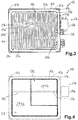
- Fig. 5 12 is an arrangement 31a of two heating devices 11a according to or similar to the illustration in FIG Fig. 2 shown. However, only the left heating device 11a can be seen exactly as in FIG Fig. 1 respectively. Fig. 2 formed, the right heating device 11a is only of the same design in principle, that is to say with partial heating surfaces of the same size. Strictly speaking, it is mirror-symmetrical to the left heating device 11a formed with a mirror axis along a center line 32a which runs between the two heating devices 11a and 11a '.
- FIG. 6 Another arrangement 31b is shown, which is basically constructed similarly to that from Fig. 5 , On the left is a heater 11b according to 3 and 4 intended. Another heating device 11b 'is provided directly to the right and only separated by a center line 32b, which has the same size and the same outer shape. It is similar to before Fig. 5 described, mirror-symmetrical to the left heating device 11b, which makes it possible for the first two partial heating surfaces 1THb and 1THb 'to be mirror-symmetrical and to bear against one another with their outer sides facing one another.
- the thickness of the respective outer edge 15 is not taken into account when it is shown how partial heating surfaces or entire heating surfaces can abut one another or continue.
- the principle underlying the invention is nevertheless easy to understand and understand.
- a top view of a cooktop 35 according to the invention is shown in a first embodiment of the invention.
- the hob 35 has four heating devices 11, namely two heating devices 11a and 11a 'with a square outer shape and two heating devices 11b or 11b 'with a rectangular outer shape.
- An operating device 36 is arranged in the front in the middle, advantageously with touch switches.
- a heating device 11a or 11a ' with a square outer shape and a heating device 11b or 11b' with a rectangular outer shape are combined on the left and right and installed close to one another. You can even touch. It can be seen how the heater 11a 'corresponds to the Fig. 5 the first partial heating surface 1THa 'is placed in the upper left corner. To the right and below is the second partial heating surface 2THa '.
- the first partial heating surface 1THb is arranged in the lower left corner, and the L-shaped second partial heating surface 2THb extends to the right and above.
- the offset is chosen differently than on the left as an example for as many different possible arrangements.
- the two heating devices are still in direct contact with one another, as are the first partial heating surfaces 1THa 'and 1THb.
- the adjacent outer sides are no longer congruent, but somewhat offset from one another.
- they can each be arranged in the corners of the respective heating device, but the same heating devices 11 can be used on the left and right in the hob 35.
- the offset of the first two partial heating surfaces can be a bit surprising in practice, but it is only marginally disturbing thermally.
- FIG. 8 Another cooktop 135 according to the invention Fig. 8 has two heating devices 11a on the left accordingly 1 and 2 that are adjacent to each other, but are not congruent, but are somewhat offset. Their outer shape is square. However, the first partial heating surfaces 1THa are congruent with each other.
- two further square heating devices 11a ′′ are arranged next to one another but offset from one another.
- a respective first partial heating surface 1THa ′′ is designed to abut on an outside or on the outside edge, but only on an outside. It is not arranged in the corner, so to speak. This makes it possible for the two heating devices 11a "are arranged offset from one another and the first partial heating surfaces 1THa" do not just sit in the corner, but are nevertheless arranged congruently next to one another.
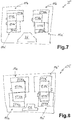
- FIG. 9 Another cooktop 235 according to the invention is shown, in which an arrangement 31a corresponding to the left behind a front central operating device 236 corresponds Fig. 5 a heater 11a and a heater 11a is provided.
- a heater 11a In the right half of the hob 235 there are two round heating devices, namely a small round heating device 35c at the front and a larger round heating device 35d at the rear. These have no subdivision into different partial heating surfaces at all. Due to their size, they are well adapted to the available space also because of the operating device 236.
- heating devices 111a and 111a ' are to be arranged very close to one another or in an abutting manner.
- a special feature of these heating devices 111a and 111a ', each of which has a square outer shape, is that their first partial heating surfaces 1THa and 1THa' abut each other in the middle or in the common central region and form an essentially closed or continuous surface , They are all the same size.
- the diagonally opposite heating devices 111a and 111a ' are each identical, the other mirror-symmetrical to it.
- the very large area formed by the four partial heating surfaces 1THa and 1THa 'involved can be used to heat very large cooking vessels such as paella pans. It is also conceivable to completely operate the four entire heating devices 111a and 111a 'with all partial heating surfaces 1THa, 1THa', 2THa and 2THa 'for such paella pans or the like.
- the associated second partial heating surfaces 2THa and 2THa ' are then grouped together as a kind of rectangular ring around them.
- different bridge functions or bridge arrangements and thus a total interconnection of heating surfaces or partial heating surfaces are possible in order to be able to optimally heat different sized cooking vessels.
- Technically somewhat more difficult or complex is an internal electrical connection to the first partial heating surfaces 1THa and 1THa 'because they do not adjoin an exposed outside of the heating device. This can also be done by installing a suitable heating conductor.
- the heaters 111a and 111a 'so far apart it is possible to remove that an electrical connection possibility is created in an intermediate space.
Landscapes
- Engineering & Computer Science (AREA)
- Chemical & Material Sciences (AREA)
- Combustion & Propulsion (AREA)
- Mechanical Engineering (AREA)
- General Engineering & Computer Science (AREA)
- Ceramic Engineering (AREA)
- Electric Stoves And Ranges (AREA)
- Control Of Resistance Heating (AREA)
Priority Applications (1)
| Application Number | Priority Date | Filing Date | Title |
|---|---|---|---|
| PL19185136.9T PL3598848T5 (pl) | 2018-07-19 | 2019-07-09 | płyta kuchenna |
Applications Claiming Priority (1)
| Application Number | Priority Date | Filing Date | Title |
|---|---|---|---|
| DE102018212094.3A DE102018212094A1 (de) | 2018-07-19 | 2018-07-19 | Heizeinrichtung für ein Kochfeld und Kochfeld |
Publications (3)
| Publication Number | Publication Date |
|---|---|
| EP3598848A1 true EP3598848A1 (fr) | 2020-01-22 |
| EP3598848B1 EP3598848B1 (fr) | 2021-03-31 |
| EP3598848B2 EP3598848B2 (fr) | 2024-05-15 |
Family
ID=67220690
Family Applications (1)
| Application Number | Title | Priority Date | Filing Date |
|---|---|---|---|
| EP19185136.9A Active EP3598848B2 (fr) | 2018-07-19 | 2019-07-09 | Table de cuisson |
Country Status (5)
| Country | Link |
|---|---|
| US (1) | US11156365B2 (fr) |
| EP (1) | EP3598848B2 (fr) |
| DE (1) | DE102018212094A1 (fr) |
| ES (1) | ES2875934T5 (fr) |
| PL (1) | PL3598848T5 (fr) |
Families Citing this family (3)
| Publication number | Priority date | Publication date | Assignee | Title |
|---|---|---|---|---|
| DE102016224069A1 (de) * | 2016-12-02 | 2018-06-07 | E.G.O. Elektro-Gerätebau GmbH | Kochgerät mit einer Kochplatte und einer Heizeinrichtung darunter |
| DE102021202613A1 (de) | 2021-03-18 | 2022-09-22 | E.G.O. Elektro-Gerätebau GmbH | Heizeinrichtung für ein Kochfeld und Kochfeld |
| US20230059706A1 (en) * | 2021-08-19 | 2023-02-23 | Enders Colsman Ag | Electric grill appliance and heating element therefor |
Citations (7)
| Publication number | Priority date | Publication date | Assignee | Title |
|---|---|---|---|---|
| US4073970A (en) * | 1975-10-17 | 1978-02-14 | Corning Glass Works | Method of making electric heating unit |
| DE3407965A1 (de) * | 1984-03-03 | 1985-09-05 | E.G.O. Elektro-Geräte Blanc u. Fischer, 7519 Oberderdingen | Grillplatte |
| DE3613902A1 (de) | 1986-04-24 | 1987-10-29 | Ego Elektro Blanc & Fischer | Kochplatte, insbesondere fuer grosskuechen-herde |
| DE3705260A1 (de) | 1987-02-19 | 1988-09-01 | Ego Elektro Blanc & Fischer | Temperaturbegrenzer |
| DE4007680A1 (de) * | 1990-03-10 | 1991-09-19 | Grass Ag | Heizplatte |
| US20050051533A1 (en) * | 2003-09-09 | 2005-03-10 | Samsung Electronics Co., Ltd. | Electric cooking apparatus and method of controlling the same |
| DE102004058473A1 (de) | 2004-11-24 | 2006-06-08 | E.G.O. Elektro-Gerätebau GmbH | Heizeinrichtung, insbesondere Strahlungsheizkörper |
Family Cites Families (16)
| Publication number | Priority date | Publication date | Assignee | Title |
|---|---|---|---|---|
| US3130664A (en) | 1960-10-13 | 1964-04-28 | Wells Mfg Company | Griddle plate assembly and method of making same |
| GB2081889B (en) | 1980-07-25 | 1984-07-11 | Kenwood Mfg Co Ltd | Cooker grill |
| EP0234373A3 (fr) | 1986-02-26 | 1988-03-02 | E.G.O. Elektro-Geräte Blanc u. Fischer | Unité de cuisson avec élément chauffant radiant |
| DE3606794A1 (de) * | 1986-03-01 | 1987-09-03 | Ego Elektro Blanc & Fischer | Elektrokochplatte |
| US5413032A (en) | 1994-08-18 | 1995-05-09 | The Middleby Corporation | Restaurant type griddle with modular construction and which is load sensitive |
| US6621054B2 (en) * | 1997-01-26 | 2003-09-16 | Horst Mosshammer Von Mosshaim | Modular hot plates |
| GB2392499B (en) * | 2002-08-24 | 2005-10-05 | Ceramaspeed Ltd | Electric heater |
| DE102006057885A1 (de) | 2006-12-01 | 2008-06-05 | E.G.O. Elektro-Gerätebau GmbH | Verfahren zum Erzeugen, Verarbeiten und Auswerten eines mit der Temperatur korrelierten Signals und entsprechende Vorrichtung |
| US20100199857A1 (en) | 2007-07-10 | 2010-08-12 | Paul Storiz | Multi-zone composite cooking griddle with unitary thermally conductive plate |
| ES2324449B1 (es) | 2007-07-31 | 2010-05-25 | Bsh Electrodomesticos España, S.A | Campo de coccion con una pluralidad de elementos de calentamiento y procedimiento para el accionamiento de un campo de coccion. |
| EP2133012B1 (fr) | 2008-06-12 | 2015-02-25 | Electrolux Home Products Corporation N.V. | Dispositif de cuisson doté d'une plaque chaude et d'un élément de chauffage |
| EP3028535B2 (fr) * | 2013-07-31 | 2022-09-21 | BSH Hausgeräte GmbH | Système de table de cuisson |
| US9677177B2 (en) * | 2013-10-24 | 2017-06-13 | Applied Materials, Inc. | Substrate support with quadrants |
| WO2015062859A1 (fr) | 2013-11-04 | 2015-05-07 | BSH Hausgeräte GmbH | Dispositif de cuisson équipé d'une plaque de chauffage |
| FR3032873A1 (fr) | 2015-02-23 | 2016-08-26 | Matit | Plancha electrique a usage interieur et/ou exterieur offrant une temperature de 320° celsius parfaitement repartie sur la plaque de cuisson, plaque de cuisson amovible |
| MA41646A (fr) | 2015-03-05 | 2018-01-09 | Spectrum Brands Inc | Gril de cuisson électrique à usages multiples |
-
2018
- 2018-07-19 DE DE102018212094.3A patent/DE102018212094A1/de not_active Withdrawn
-
2019
- 2019-07-09 EP EP19185136.9A patent/EP3598848B2/fr active Active
- 2019-07-09 PL PL19185136.9T patent/PL3598848T5/pl unknown
- 2019-07-09 ES ES19185136T patent/ES2875934T5/es active Active
- 2019-07-11 US US16/508,656 patent/US11156365B2/en active Active
Patent Citations (7)
| Publication number | Priority date | Publication date | Assignee | Title |
|---|---|---|---|---|
| US4073970A (en) * | 1975-10-17 | 1978-02-14 | Corning Glass Works | Method of making electric heating unit |
| DE3407965A1 (de) * | 1984-03-03 | 1985-09-05 | E.G.O. Elektro-Geräte Blanc u. Fischer, 7519 Oberderdingen | Grillplatte |
| DE3613902A1 (de) | 1986-04-24 | 1987-10-29 | Ego Elektro Blanc & Fischer | Kochplatte, insbesondere fuer grosskuechen-herde |
| DE3705260A1 (de) | 1987-02-19 | 1988-09-01 | Ego Elektro Blanc & Fischer | Temperaturbegrenzer |
| DE4007680A1 (de) * | 1990-03-10 | 1991-09-19 | Grass Ag | Heizplatte |
| US20050051533A1 (en) * | 2003-09-09 | 2005-03-10 | Samsung Electronics Co., Ltd. | Electric cooking apparatus and method of controlling the same |
| DE102004058473A1 (de) | 2004-11-24 | 2006-06-08 | E.G.O. Elektro-Gerätebau GmbH | Heizeinrichtung, insbesondere Strahlungsheizkörper |
Also Published As
| Publication number | Publication date |
|---|---|
| ES2875934T5 (en) | 2024-12-18 |
| ES2875934T3 (es) | 2021-11-11 |
| EP3598848B1 (fr) | 2021-03-31 |
| PL3598848T5 (pl) | 2024-09-16 |
| DE102018212094A1 (de) | 2020-01-23 |
| EP3598848B2 (fr) | 2024-05-15 |
| US11156365B2 (en) | 2021-10-26 |
| US20200025388A1 (en) | 2020-01-23 |
| PL3598848T3 (pl) | 2021-10-18 |
Similar Documents
| Publication | Publication Date | Title |
|---|---|---|
| EP3331319B1 (fr) | Appareil de cuisson doté d'une plaque de cuisson et d'un dispositif de chauffage correspondant | |
| WO2008058614A1 (fr) | Zone de cuisson à induction, table de cuisson à induction et procédé d'excitation | |
| EP2268101B1 (fr) | Fond de creuset, appareil de cuisson et procédé de fonctionnement d'un tel appareil de cuisson | |
| EP3598848B1 (fr) | Dispositif de chauffage pour une table de cuisson et table de cuisson | |
| EP2844029A1 (fr) | Dispositif de chauffage et son procédé de fonctionnement | |
| EP2574146A2 (fr) | Dispositif de chauffage à induction et champ de cuisson à induction avec plusieurs dispositifs de chauffage à induction de ce type | |
| DE60003700T2 (de) | Toastgerät mit einer erhitzungsvorrichtung für brötchen oder gleichartige nahrungsmittel | |
| EP3614797A1 (fr) | Dispositif de chauffage et procédé de fonctionnement d'un dispositif de chauffage | |
| EP1916876A1 (fr) | Dispositif de chauffage par induction | |
| EP3764739B1 (fr) | Dispositif de préparation des aliments pourvu de résistances à coefficient de température positive électriques montées en parallèle | |
| EP3300455A1 (fr) | Plaque de cuisson et procédé de positionnement d'un dispositif de chauffage sur plaque de cuisson | |
| EP3337291B1 (fr) | Dispositif de chauffage, appareil de cuisson doté d'un dispositif de chauffage et procédé de fabrication d'un élément chauffant | |
| EP0136655A2 (fr) | Plaque de cuisson électrique | |
| EP3498136A1 (fr) | Partie de fond pour une machine de cuisine | |
| EP3644688A1 (fr) | Chauffage et appareil de cuisson électrique | |
| DE2747652A1 (de) | Elektrokochgeraet | |
| EP2464194B1 (fr) | Chauffage pour appareils domestiques | |
| WO2015062859A1 (fr) | Dispositif de cuisson équipé d'une plaque de chauffage | |
| DE102020200694B4 (de) | Verfahren zum Betrieb einer Kochfeldvorrichtung und Kochfeldvorrichtung | |
| EP3771287A1 (fr) | Dispositif chauffant à rayonnement et plaque de cuisson dotée d'un tel dispositif chauffant à rayonnement | |
| DE102014208409A1 (de) | Heizkörper für ein Gargerät sowie Gargerät mit einem Heizkörper | |
| EP3820246B1 (fr) | Dispositif de chauffage électrique, plaque de cuisson et procédé de fonctionnement du dispositif de chauffage | |
| DE102018205970A1 (de) | Heizkörper für ein Gargerät und Gargerät | |
| EP3261409A1 (fr) | Procédé de fabrication d'un dispositif de chauffage et dispositif de chauffage | |
| DE102019216020A1 (de) | Verfahren zum Betrieb einer Strahlungsheizeinrichtung und Kombination einer Strahlungsheizeinrichtung mit einer Drehschalteinrichtung |
Legal Events
| Date | Code | Title | Description |
|---|---|---|---|
| PUAI | Public reference made under article 153(3) epc to a published international application that has entered the european phase |
Free format text: ORIGINAL CODE: 0009012 |
|
| STAA | Information on the status of an ep patent application or granted ep patent |
Free format text: STATUS: THE APPLICATION HAS BEEN PUBLISHED |
|
| AK | Designated contracting states |
Kind code of ref document: A1 Designated state(s): AL AT BE BG CH CY CZ DE DK EE ES FI FR GB GR HR HU IE IS IT LI LT LU LV MC MK MT NL NO PL PT RO RS SE SI SK SM TR |
|
| AX | Request for extension of the european patent |
Extension state: BA ME |
|
| STAA | Information on the status of an ep patent application or granted ep patent |
Free format text: STATUS: REQUEST FOR EXAMINATION WAS MADE |
|
| 17P | Request for examination filed |
Effective date: 20200707 |
|
| RBV | Designated contracting states (corrected) |
Designated state(s): AL AT BE BG CH CY CZ DE DK EE ES FI FR GB GR HR HU IE IS IT LI LT LU LV MC MK MT NL NO PL PT RO RS SE SI SK SM TR |
|
| GRAP | Despatch of communication of intention to grant a patent |
Free format text: ORIGINAL CODE: EPIDOSNIGR1 |
|
| STAA | Information on the status of an ep patent application or granted ep patent |
Free format text: STATUS: GRANT OF PATENT IS INTENDED |
|
| INTG | Intention to grant announced |
Effective date: 20201110 |
|
| GRAS | Grant fee paid |
Free format text: ORIGINAL CODE: EPIDOSNIGR3 |
|
| GRAA | (expected) grant |
Free format text: ORIGINAL CODE: 0009210 |
|
| STAA | Information on the status of an ep patent application or granted ep patent |
Free format text: STATUS: THE PATENT HAS BEEN GRANTED |
|
| AK | Designated contracting states |
Kind code of ref document: B1 Designated state(s): AL AT BE BG CH CY CZ DE DK EE ES FI FR GB GR HR HU IE IS IT LI LT LU LV MC MK MT NL NO PL PT RO RS SE SI SK SM TR |
|
| REG | Reference to a national code |
Ref country code: GB Ref legal event code: FG4D Free format text: NOT ENGLISH Ref country code: CH Ref legal event code: EP |
|
| REG | Reference to a national code |
Ref country code: DE Ref legal event code: R096 Ref document number: 502019001096 Country of ref document: DE Ref country code: AT Ref legal event code: REF Ref document number: 1378435 Country of ref document: AT Kind code of ref document: T Effective date: 20210415 |
|
| REG | Reference to a national code |
Ref country code: IE Ref legal event code: FG4D Free format text: LANGUAGE OF EP DOCUMENT: GERMAN |
|
| REG | Reference to a national code |
Ref country code: LT Ref legal event code: MG9D |
|
| PG25 | Lapsed in a contracting state [announced via postgrant information from national office to epo] |
Ref country code: NO Free format text: LAPSE BECAUSE OF FAILURE TO SUBMIT A TRANSLATION OF THE DESCRIPTION OR TO PAY THE FEE WITHIN THE PRESCRIBED TIME-LIMIT Effective date: 20210630 Ref country code: FI Free format text: LAPSE BECAUSE OF FAILURE TO SUBMIT A TRANSLATION OF THE DESCRIPTION OR TO PAY THE FEE WITHIN THE PRESCRIBED TIME-LIMIT Effective date: 20210331 Ref country code: HR Free format text: LAPSE BECAUSE OF FAILURE TO SUBMIT A TRANSLATION OF THE DESCRIPTION OR TO PAY THE FEE WITHIN THE PRESCRIBED TIME-LIMIT Effective date: 20210331 Ref country code: BG Free format text: LAPSE BECAUSE OF FAILURE TO SUBMIT A TRANSLATION OF THE DESCRIPTION OR TO PAY THE FEE WITHIN THE PRESCRIBED TIME-LIMIT Effective date: 20210630 |
|
| PG25 | Lapsed in a contracting state [announced via postgrant information from national office to epo] |
Ref country code: LV Free format text: LAPSE BECAUSE OF FAILURE TO SUBMIT A TRANSLATION OF THE DESCRIPTION OR TO PAY THE FEE WITHIN THE PRESCRIBED TIME-LIMIT Effective date: 20210331 Ref country code: SE Free format text: LAPSE BECAUSE OF FAILURE TO SUBMIT A TRANSLATION OF THE DESCRIPTION OR TO PAY THE FEE WITHIN THE PRESCRIBED TIME-LIMIT Effective date: 20210331 Ref country code: RS Free format text: LAPSE BECAUSE OF FAILURE TO SUBMIT A TRANSLATION OF THE DESCRIPTION OR TO PAY THE FEE WITHIN THE PRESCRIBED TIME-LIMIT Effective date: 20210331 |
|
| REG | Reference to a national code |
Ref country code: NL Ref legal event code: MP Effective date: 20210331 |
|
| PG25 | Lapsed in a contracting state [announced via postgrant information from national office to epo] |
Ref country code: EE Free format text: LAPSE BECAUSE OF FAILURE TO SUBMIT A TRANSLATION OF THE DESCRIPTION OR TO PAY THE FEE WITHIN THE PRESCRIBED TIME-LIMIT Effective date: 20210331 Ref country code: CZ Free format text: LAPSE BECAUSE OF FAILURE TO SUBMIT A TRANSLATION OF THE DESCRIPTION OR TO PAY THE FEE WITHIN THE PRESCRIBED TIME-LIMIT Effective date: 20210331 Ref country code: LT Free format text: LAPSE BECAUSE OF FAILURE TO SUBMIT A TRANSLATION OF THE DESCRIPTION OR TO PAY THE FEE WITHIN THE PRESCRIBED TIME-LIMIT Effective date: 20210331 Ref country code: NL Free format text: LAPSE BECAUSE OF FAILURE TO SUBMIT A TRANSLATION OF THE DESCRIPTION OR TO PAY THE FEE WITHIN THE PRESCRIBED TIME-LIMIT Effective date: 20210331 Ref country code: SM Free format text: LAPSE BECAUSE OF FAILURE TO SUBMIT A TRANSLATION OF THE DESCRIPTION OR TO PAY THE FEE WITHIN THE PRESCRIBED TIME-LIMIT Effective date: 20210331 |
|
| REG | Reference to a national code |
Ref country code: ES Ref legal event code: FG2A Ref document number: 2875934 Country of ref document: ES Kind code of ref document: T3 Effective date: 20211111 |
|
| PG25 | Lapsed in a contracting state [announced via postgrant information from national office to epo] |
Ref country code: SK Free format text: LAPSE BECAUSE OF FAILURE TO SUBMIT A TRANSLATION OF THE DESCRIPTION OR TO PAY THE FEE WITHIN THE PRESCRIBED TIME-LIMIT Effective date: 20210331 Ref country code: RO Free format text: LAPSE BECAUSE OF FAILURE TO SUBMIT A TRANSLATION OF THE DESCRIPTION OR TO PAY THE FEE WITHIN THE PRESCRIBED TIME-LIMIT Effective date: 20210331 Ref country code: PT Free format text: LAPSE BECAUSE OF FAILURE TO SUBMIT A TRANSLATION OF THE DESCRIPTION OR TO PAY THE FEE WITHIN THE PRESCRIBED TIME-LIMIT Effective date: 20210802 Ref country code: IS Free format text: LAPSE BECAUSE OF FAILURE TO SUBMIT A TRANSLATION OF THE DESCRIPTION OR TO PAY THE FEE WITHIN THE PRESCRIBED TIME-LIMIT Effective date: 20210731 |
|
| REG | Reference to a national code |
Ref country code: DE Ref legal event code: R026 Ref document number: 502019001096 Country of ref document: DE |
|
| PLBI | Opposition filed |
Free format text: ORIGINAL CODE: 0009260 |
|
| PLAX | Notice of opposition and request to file observation + time limit sent |
Free format text: ORIGINAL CODE: EPIDOSNOBS2 |
|
| 26 | Opposition filed |
Opponent name: AWA BENELUX SA Effective date: 20211222 |
|
| PG25 | Lapsed in a contracting state [announced via postgrant information from national office to epo] |
Ref country code: AL Free format text: LAPSE BECAUSE OF FAILURE TO SUBMIT A TRANSLATION OF THE DESCRIPTION OR TO PAY THE FEE WITHIN THE PRESCRIBED TIME-LIMIT Effective date: 20210331 Ref country code: DK Free format text: LAPSE BECAUSE OF FAILURE TO SUBMIT A TRANSLATION OF THE DESCRIPTION OR TO PAY THE FEE WITHIN THE PRESCRIBED TIME-LIMIT Effective date: 20210331 |
|
| PG25 | Lapsed in a contracting state [announced via postgrant information from national office to epo] |
Ref country code: MC Free format text: LAPSE BECAUSE OF FAILURE TO SUBMIT A TRANSLATION OF THE DESCRIPTION OR TO PAY THE FEE WITHIN THE PRESCRIBED TIME-LIMIT Effective date: 20210331 |
|
| REG | Reference to a national code |
Ref country code: BE Ref legal event code: MM Effective date: 20210731 |
|
| PLBB | Reply of patent proprietor to notice(s) of opposition received |
Free format text: ORIGINAL CODE: EPIDOSNOBS3 |
|
| PG25 | Lapsed in a contracting state [announced via postgrant information from national office to epo] |
Ref country code: IS Free format text: LAPSE BECAUSE OF FAILURE TO SUBMIT A TRANSLATION OF THE DESCRIPTION OR TO PAY THE FEE WITHIN THE PRESCRIBED TIME-LIMIT Effective date: 20210731 Ref country code: LU Free format text: LAPSE BECAUSE OF NON-PAYMENT OF DUE FEES Effective date: 20210709 |
|
| PG25 | Lapsed in a contracting state [announced via postgrant information from national office to epo] |
Ref country code: BE Free format text: LAPSE BECAUSE OF NON-PAYMENT OF DUE FEES Effective date: 20210731 Ref country code: IE Free format text: LAPSE BECAUSE OF NON-PAYMENT OF DUE FEES Effective date: 20210709 |
|
| REG | Reference to a national code |
Ref country code: CH Ref legal event code: PL |
|
| APBM | Appeal reference recorded |
Free format text: ORIGINAL CODE: EPIDOSNREFNO |
|
| APBP | Date of receipt of notice of appeal recorded |
Free format text: ORIGINAL CODE: EPIDOSNNOA2O |
|
| APAH | Appeal reference modified |
Free format text: ORIGINAL CODE: EPIDOSCREFNO |
|
| PG25 | Lapsed in a contracting state [announced via postgrant information from national office to epo] |
Ref country code: LI Free format text: LAPSE BECAUSE OF NON-PAYMENT OF DUE FEES Effective date: 20220731 Ref country code: CH Free format text: LAPSE BECAUSE OF NON-PAYMENT OF DUE FEES Effective date: 20220731 |
|
| APBQ | Date of receipt of statement of grounds of appeal recorded |
Free format text: ORIGINAL CODE: EPIDOSNNOA3O |
|
| PG25 | Lapsed in a contracting state [announced via postgrant information from national office to epo] |
Ref country code: CY Free format text: LAPSE BECAUSE OF FAILURE TO SUBMIT A TRANSLATION OF THE DESCRIPTION OR TO PAY THE FEE WITHIN THE PRESCRIBED TIME-LIMIT Effective date: 20210331 |
|
| PG25 | Lapsed in a contracting state [announced via postgrant information from national office to epo] |
Ref country code: HU Free format text: LAPSE BECAUSE OF FAILURE TO SUBMIT A TRANSLATION OF THE DESCRIPTION OR TO PAY THE FEE WITHIN THE PRESCRIBED TIME-LIMIT; INVALID AB INITIO Effective date: 20190709 Ref country code: GR Free format text: LAPSE BECAUSE OF FAILURE TO SUBMIT A TRANSLATION OF THE DESCRIPTION OR TO PAY THE FEE WITHIN THE PRESCRIBED TIME-LIMIT Effective date: 20210331 |
|
| APBU | Appeal procedure closed |
Free format text: ORIGINAL CODE: EPIDOSNNOA9O |
|
| REG | Reference to a national code |
Ref country code: CH Ref legal event code: PK Free format text: TITEL |
|
| GBPC | Gb: european patent ceased through non-payment of renewal fee |
Effective date: 20230709 |
|
| PUAH | Patent maintained in amended form |
Free format text: ORIGINAL CODE: 0009272 |
|
| STAA | Information on the status of an ep patent application or granted ep patent |
Free format text: STATUS: PATENT MAINTAINED AS AMENDED |
|
| PG25 | Lapsed in a contracting state [announced via postgrant information from national office to epo] |
Ref country code: MK Free format text: LAPSE BECAUSE OF FAILURE TO SUBMIT A TRANSLATION OF THE DESCRIPTION OR TO PAY THE FEE WITHIN THE PRESCRIBED TIME-LIMIT Effective date: 20210331 Ref country code: GB Free format text: LAPSE BECAUSE OF NON-PAYMENT OF DUE FEES Effective date: 20230709 |
|
| REG | Reference to a national code |
Ref country code: CH Ref legal event code: PK Free format text: DIE PUBLIKATION VOM 17.04.2024 WURDE AM 24.04.2024 IRRTUEMLICHERWEISE ERNEUT PUBLIZIERT. LA PUBLICATION DU 17.04.2024 A ETE REPUBLIEE PAR ERREUR LE 24.04.2024. LA PUBBLICAZIONE DEL 17.04.2024 E STATA ERRONEAMENTE RIPUBBLICATA IL 24.04.2024. |
|
| 27A | Patent maintained in amended form |
Effective date: 20240515 |
|
| AK | Designated contracting states |
Kind code of ref document: B2 Designated state(s): AL AT BE BG CH CY CZ DE DK EE ES FI FR GB GR HR HU IE IS IT LI LT LU LV MC MK MT NL NO PL PT RO RS SE SI SK SM TR |
|
| REG | Reference to a national code |
Ref country code: DE Ref legal event code: R102 Ref document number: 502019001096 Country of ref document: DE |
|
| PG25 | Lapsed in a contracting state [announced via postgrant information from national office to epo] |
Ref country code: MT Free format text: LAPSE BECAUSE OF FAILURE TO SUBMIT A TRANSLATION OF THE DESCRIPTION OR TO PAY THE FEE WITHIN THE PRESCRIBED TIME-LIMIT Effective date: 20210331 |
|
| REG | Reference to a national code |
Ref country code: ES Ref legal event code: DC2A Ref document number: 2875934 Country of ref document: ES Kind code of ref document: T5 Effective date: 20241218 |
|
| PGFP | Annual fee paid to national office [announced via postgrant information from national office to epo] |
Ref country code: PL Payment date: 20250616 Year of fee payment: 7 |
|
| REG | Reference to a national code |
Ref country code: AT Ref legal event code: MM01 Ref document number: 1378435 Country of ref document: AT Kind code of ref document: T Effective date: 20240709 |
|
| PGFP | Annual fee paid to national office [announced via postgrant information from national office to epo] |
Ref country code: ES Payment date: 20250819 Year of fee payment: 7 |
|
| PGFP | Annual fee paid to national office [announced via postgrant information from national office to epo] |
Ref country code: DE Payment date: 20250723 Year of fee payment: 7 |
|
| PGFP | Annual fee paid to national office [announced via postgrant information from national office to epo] |
Ref country code: TR Payment date: 20250703 Year of fee payment: 7 Ref country code: IT Payment date: 20250731 Year of fee payment: 7 |
|
| PG25 | Lapsed in a contracting state [announced via postgrant information from national office to epo] |
Ref country code: AT Free format text: LAPSE BECAUSE OF NON-PAYMENT OF DUE FEES Effective date: 20240709 |
|
| PGFP | Annual fee paid to national office [announced via postgrant information from national office to epo] |
Ref country code: FR Payment date: 20250723 Year of fee payment: 7 |
|
| PGFP | Annual fee paid to national office [announced via postgrant information from national office to epo] |
Ref country code: AT Payment date: 20260410 Year of fee payment: 5 |