EP3601304B1 - Metallkomplexe - Google Patents
Metallkomplexe Download PDFInfo
- Publication number
- EP3601304B1 EP3601304B1 EP18712235.3A EP18712235A EP3601304B1 EP 3601304 B1 EP3601304 B1 EP 3601304B1 EP 18712235 A EP18712235 A EP 18712235A EP 3601304 B1 EP3601304 B1 EP 3601304B1
- Authority
- EP
- European Patent Office
- Prior art keywords
- group
- carbon atoms
- radicals
- formula
- substituted
- Prior art date
- Legal status (The legal status is an assumption and is not a legal conclusion. Google has not performed a legal analysis and makes no representation as to the accuracy of the status listed.)
- Active
Links
- 0 Cc1cc2ccc(c(*=C)c(*=C)c(C=*)c3)c3c2cc1 Chemical compound Cc1cc2ccc(c(*=C)c(*=C)c(C=*)c3)c3c2cc1 0.000 description 25
- ZWJYXJDEDLXUHU-UHFFFAOYSA-N Brc1cc(cccc2)c2cn1 Chemical compound Brc1cc(cccc2)c2cn1 ZWJYXJDEDLXUHU-UHFFFAOYSA-N 0.000 description 1
- CVOCFDLLZQEKHG-UHFFFAOYSA-N C/[O]=C1/[n](c(c(c2cc(-c3cc(-c4ccccc4)ccc3)c3)c4)ccc4-c4cccc(-c5ccccc5)c4)c2c3-c2c1cccc2 Chemical compound C/[O]=C1/[n](c(c(c2cc(-c3cc(-c4ccccc4)ccc3)c3)c4)ccc4-c4cccc(-c5ccccc5)c4)c2c3-c2c1cccc2 CVOCFDLLZQEKHG-UHFFFAOYSA-N 0.000 description 1
- UKFDZDMYNCAOJE-UHFFFAOYSA-N CC(C)(C)c1nc(cc(cc2)-c(cccc3)c3-c3cc(B4OC(C)(C)C(C)(C)O4)cc(-c(cccc4)c4-c4ccc(c5nc(cc(C(C)(C)CC6(C)C)c6c6)c6[n]5c(C(C)(C)C)n5)c5c4)c3)c2c2nc3cc(C(C)(C)CC4(C)C)c4cc3[n]12 Chemical compound CC(C)(C)c1nc(cc(cc2)-c(cccc3)c3-c3cc(B4OC(C)(C)C(C)(C)O4)cc(-c(cccc4)c4-c4ccc(c5nc(cc(C(C)(C)CC6(C)C)c6c6)c6[n]5c(C(C)(C)C)n5)c5c4)c3)c2c2nc3cc(C(C)(C)CC4(C)C)c4cc3[n]12 UKFDZDMYNCAOJE-UHFFFAOYSA-N 0.000 description 1
- GUFDIISOXTUABX-UHFFFAOYSA-N CC(C)(CC1(C)C)C2=C1N(C=Cc1cc(-c3ccccc3-c3cc(-c4ccccc4-c(cc4)cc(C=CN5C6=C7C(C)(C)CC6(C)C)c4C5=NC7=O)cc(Cl)c3)ccc11)C1=NC2=O Chemical compound CC(C)(CC1(C)C)C2=C1N(C=Cc1cc(-c3ccccc3-c3cc(-c4ccccc4-c(cc4)cc(C=CN5C6=C7C(C)(C)CC6(C)C)c4C5=NC7=O)cc(Cl)c3)ccc11)C1=NC2=O GUFDIISOXTUABX-UHFFFAOYSA-N 0.000 description 1
- NAIFOJZJFLPWGD-UHFFFAOYSA-N CC(C)(c1ccccc1-c1c2)c1cc1c2c2cc(-c(cc3)cc(c4c5cccc4)c3[n]5-c3ccccc3)ccc2[n]1-c1ccccc1 Chemical compound CC(C)(c1ccccc1-c1c2)c1cc1c2c2cc(-c(cc3)cc(c4c5cccc4)c3[n]5-c3ccccc3)ccc2[n]1-c1ccccc1 NAIFOJZJFLPWGD-UHFFFAOYSA-N 0.000 description 1
- UFVDAZZCEFZOII-UHFFFAOYSA-N CC1(C)OB(c(c(OC)c2)ccc2-c2nccc(C)c2)OC1(C)C Chemical compound CC1(C)OB(c(c(OC)c2)ccc2-c2nccc(C)c2)OC1(C)C UFVDAZZCEFZOII-UHFFFAOYSA-N 0.000 description 1
- IQFGNOVULCLFPH-UHFFFAOYSA-N CC1(C)OB(c(cc2)cc3c2c(cccc2)c2[o]3)OC1(C)C Chemical compound CC1(C)OB(c(cc2)cc3c2c(cccc2)c2[o]3)OC1(C)C IQFGNOVULCLFPH-UHFFFAOYSA-N 0.000 description 1
- AENYFLSFGATXJM-UHFFFAOYSA-N CC1(C)OB(c(cc2)cc3c2c2nc(C)c[n]2cc3)OC1(C)C Chemical compound CC1(C)OB(c(cc2)cc3c2c2nc(C)c[n]2cc3)OC1(C)C AENYFLSFGATXJM-UHFFFAOYSA-N 0.000 description 1
- REDKQKNJWVIPIO-UHFFFAOYSA-N CC1(C)OB(c(cc2)ccc2-c2ccccc2)OC1(C)C Chemical compound CC1(C)OB(c(cc2)ccc2-c2ccccc2)OC1(C)C REDKQKNJWVIPIO-UHFFFAOYSA-N 0.000 description 1
- JUNIPKIMQJKCQC-UHFFFAOYSA-N CC1(C)OB(c(cc2)ccc2-c2nc3ccccc3[n]2C)OC1(C)C Chemical compound CC1(C)OB(c(cc2)ccc2-c2nc3ccccc3[n]2C)OC1(C)C JUNIPKIMQJKCQC-UHFFFAOYSA-N 0.000 description 1
- PLAHBMHOFXSMJE-UHFFFAOYSA-N CC1(C)OB(c2cc(-c3ccccc3-c(cc3)ccc3-c3ncc[n]3C)cc(-c3ccccc3-c(cc3)ccc3-c3ncc[n]3C)c2)OC1(C)C Chemical compound CC1(C)OB(c2cc(-c3ccccc3-c(cc3)ccc3-c3ncc[n]3C)cc(-c3ccccc3-c(cc3)ccc3-c3ncc[n]3C)c2)OC1(C)C PLAHBMHOFXSMJE-UHFFFAOYSA-N 0.000 description 1
- MTQVNVJTIGCAFZ-UHFFFAOYSA-N CC1(C)OB(c2ccc(c3ccccc3[s]3)c3c2)OC1(C)C Chemical compound CC1(C)OB(c2ccc(c3ccccc3[s]3)c3c2)OC1(C)C MTQVNVJTIGCAFZ-UHFFFAOYSA-N 0.000 description 1
- JLNMLKFJJSXUAS-UHFFFAOYSA-N COc(cc(cc1)-c2cc3ccccc3c(-c3ccccc3)n2)c1-c(cccc1)c1Br Chemical compound COc(cc(cc1)-c2cc3ccccc3c(-c3ccccc3)n2)c1-c(cccc1)c1Br JLNMLKFJJSXUAS-UHFFFAOYSA-N 0.000 description 1
- NQDNBNRBTUDRGZ-UHFFFAOYSA-N COc1cc(-c2[n-]cccc2)ccc1Cl Chemical compound COc1cc(-c2[n-]cccc2)ccc1Cl NQDNBNRBTUDRGZ-UHFFFAOYSA-N 0.000 description 1
- UNECIYVZRDJQFW-UHFFFAOYSA-N COc1cc(-c2cc(-c3ccccc3)ccc2)ncc1Br Chemical compound COc1cc(-c2cc(-c3ccccc3)ccc2)ncc1Br UNECIYVZRDJQFW-UHFFFAOYSA-N 0.000 description 1
- DJDWOEGZGVBCMN-UHFFFAOYSA-N COc1cc(Br)ncc1Br Chemical compound COc1cc(Br)ncc1Br DJDWOEGZGVBCMN-UHFFFAOYSA-N 0.000 description 1
- XGSUAQQIGJFODO-UHFFFAOYSA-N Cc1c[n](ccc2c3ccc(-c4ccccc4-c4cc(-c(cccc5)c5-c(cc5)ccc5-c5cc(OC)ccn5)cc(-c5ccccc5-c5ccc(c6nc(C)c[n]6cc6)c6c5)c4)c2)c3n1 Chemical compound Cc1c[n](ccc2c3ccc(-c4ccccc4-c4cc(-c(cccc5)c5-c(cc5)ccc5-c5cc(OC)ccn5)cc(-c5ccccc5-c5ccc(c6nc(C)c[n]6cc6)c6c5)c4)c2)c3n1 XGSUAQQIGJFODO-UHFFFAOYSA-N 0.000 description 1
- QVEXHSBJMXMSJX-UHFFFAOYSA-N Oc1cc(-c2cc(-c3ccccc3)ccc2)ncc1-c(cccc1)c1-c1cc(-c2ccccc2-c2ccc(-c3ccccc3)nc2)cc(-c2ccccc2-c2ccc(-c3ccccc3)nc2)c1 Chemical compound Oc1cc(-c2cc(-c3ccccc3)ccc2)ncc1-c(cccc1)c1-c1cc(-c2ccccc2-c2ccc(-c3ccccc3)nc2)cc(-c2ccccc2-c2ccc(-c3ccccc3)nc2)c1 QVEXHSBJMXMSJX-UHFFFAOYSA-N 0.000 description 1
- DEECBJZHFWCFGJ-UHFFFAOYSA-N c(cc1)ccc1-c1nc(-[n](c(cccc2)c2c2c3)c2ccc3-c(cc2c3ccccc33)ccc2[n]3-c2ccccc2)nc2c1cccc2 Chemical compound c(cc1)ccc1-c1nc(-[n](c(cccc2)c2c2c3)c2ccc3-c(cc2c3ccccc33)ccc2[n]3-c2ccccc2)nc2c1cccc2 DEECBJZHFWCFGJ-UHFFFAOYSA-N 0.000 description 1
Classifications
-
- C—CHEMISTRY; METALLURGY
- C07—ORGANIC CHEMISTRY
- C07F—ACYCLIC, CARBOCYCLIC OR HETEROCYCLIC COMPOUNDS CONTAINING ELEMENTS OTHER THAN CARBON, HYDROGEN, HALOGEN, OXYGEN, NITROGEN, SULFUR, SELENIUM OR TELLURIUM
- C07F15/00—Compounds containing elements of Groups 8, 9, 10 or 18 of the Periodic Table
- C07F15/0006—Compounds containing elements of Groups 8, 9, 10 or 18 of the Periodic Table compounds of the platinum group
- C07F15/0033—Iridium compounds
-
- C—CHEMISTRY; METALLURGY
- C09—DYES; PAINTS; POLISHES; NATURAL RESINS; ADHESIVES; COMPOSITIONS NOT OTHERWISE PROVIDED FOR; APPLICATIONS OF MATERIALS NOT OTHERWISE PROVIDED FOR
- C09K—MATERIALS FOR MISCELLANEOUS APPLICATIONS, NOT PROVIDED FOR ELSEWHERE
- C09K11/00—Luminescent materials, e.g. electroluminescent or chemiluminescent
- C09K11/06—Luminescent materials, e.g. electroluminescent or chemiluminescent containing organic luminescent materials
-
- H—ELECTRICITY
- H10—SEMICONDUCTOR DEVICES; ELECTRIC SOLID-STATE DEVICES NOT OTHERWISE PROVIDED FOR
- H10K—ORGANIC ELECTRIC SOLID-STATE DEVICES
- H10K50/00—Organic light-emitting devices
- H10K50/10—OLEDs or polymer light-emitting diodes [PLED]
- H10K50/11—OLEDs or polymer light-emitting diodes [PLED] characterised by the electroluminescent [EL] layers
-
- H—ELECTRICITY
- H10—SEMICONDUCTOR DEVICES; ELECTRIC SOLID-STATE DEVICES NOT OTHERWISE PROVIDED FOR
- H10K—ORGANIC ELECTRIC SOLID-STATE DEVICES
- H10K85/00—Organic materials used in the body or electrodes of devices covered by this subclass
- H10K85/30—Coordination compounds
- H10K85/341—Transition metal complexes, e.g. Ru(II)polypyridine complexes
- H10K85/342—Transition metal complexes, e.g. Ru(II)polypyridine complexes comprising iridium
-
- C—CHEMISTRY; METALLURGY
- C09—DYES; PAINTS; POLISHES; NATURAL RESINS; ADHESIVES; COMPOSITIONS NOT OTHERWISE PROVIDED FOR; APPLICATIONS OF MATERIALS NOT OTHERWISE PROVIDED FOR
- C09K—MATERIALS FOR MISCELLANEOUS APPLICATIONS, NOT PROVIDED FOR ELSEWHERE
- C09K2211/00—Chemical nature of organic luminescent or tenebrescent compounds
- C09K2211/10—Non-macromolecular compounds
- C09K2211/1018—Heterocyclic compounds
- C09K2211/1025—Heterocyclic compounds characterised by ligands
- C09K2211/1029—Heterocyclic compounds characterised by ligands containing one nitrogen atom as the heteroatom
- C09K2211/1033—Heterocyclic compounds characterised by ligands containing one nitrogen atom as the heteroatom with oxygen
-
- C—CHEMISTRY; METALLURGY
- C09—DYES; PAINTS; POLISHES; NATURAL RESINS; ADHESIVES; COMPOSITIONS NOT OTHERWISE PROVIDED FOR; APPLICATIONS OF MATERIALS NOT OTHERWISE PROVIDED FOR
- C09K—MATERIALS FOR MISCELLANEOUS APPLICATIONS, NOT PROVIDED FOR ELSEWHERE
- C09K2211/00—Chemical nature of organic luminescent or tenebrescent compounds
- C09K2211/10—Non-macromolecular compounds
- C09K2211/1018—Heterocyclic compounds
- C09K2211/1025—Heterocyclic compounds characterised by ligands
- C09K2211/1029—Heterocyclic compounds characterised by ligands containing one nitrogen atom as the heteroatom
- C09K2211/1037—Heterocyclic compounds characterised by ligands containing one nitrogen atom as the heteroatom with sulfur
-
- C—CHEMISTRY; METALLURGY
- C09—DYES; PAINTS; POLISHES; NATURAL RESINS; ADHESIVES; COMPOSITIONS NOT OTHERWISE PROVIDED FOR; APPLICATIONS OF MATERIALS NOT OTHERWISE PROVIDED FOR
- C09K—MATERIALS FOR MISCELLANEOUS APPLICATIONS, NOT PROVIDED FOR ELSEWHERE
- C09K2211/00—Chemical nature of organic luminescent or tenebrescent compounds
- C09K2211/10—Non-macromolecular compounds
- C09K2211/1018—Heterocyclic compounds
- C09K2211/1025—Heterocyclic compounds characterised by ligands
- C09K2211/1044—Heterocyclic compounds characterised by ligands containing two nitrogen atoms as heteroatoms
- C09K2211/1048—Heterocyclic compounds characterised by ligands containing two nitrogen atoms as heteroatoms with oxygen
-
- C—CHEMISTRY; METALLURGY
- C09—DYES; PAINTS; POLISHES; NATURAL RESINS; ADHESIVES; COMPOSITIONS NOT OTHERWISE PROVIDED FOR; APPLICATIONS OF MATERIALS NOT OTHERWISE PROVIDED FOR
- C09K—MATERIALS FOR MISCELLANEOUS APPLICATIONS, NOT PROVIDED FOR ELSEWHERE
- C09K2211/00—Chemical nature of organic luminescent or tenebrescent compounds
- C09K2211/10—Non-macromolecular compounds
- C09K2211/1018—Heterocyclic compounds
- C09K2211/1025—Heterocyclic compounds characterised by ligands
- C09K2211/1059—Heterocyclic compounds characterised by ligands containing three nitrogen atoms as heteroatoms
-
- C—CHEMISTRY; METALLURGY
- C09—DYES; PAINTS; POLISHES; NATURAL RESINS; ADHESIVES; COMPOSITIONS NOT OTHERWISE PROVIDED FOR; APPLICATIONS OF MATERIALS NOT OTHERWISE PROVIDED FOR
- C09K—MATERIALS FOR MISCELLANEOUS APPLICATIONS, NOT PROVIDED FOR ELSEWHERE
- C09K2211/00—Chemical nature of organic luminescent or tenebrescent compounds
- C09K2211/10—Non-macromolecular compounds
- C09K2211/1018—Heterocyclic compounds
- C09K2211/1025—Heterocyclic compounds characterised by ligands
- C09K2211/1074—Heterocyclic compounds characterised by ligands containing more than three nitrogen atoms as heteroatoms
-
- C—CHEMISTRY; METALLURGY
- C09—DYES; PAINTS; POLISHES; NATURAL RESINS; ADHESIVES; COMPOSITIONS NOT OTHERWISE PROVIDED FOR; APPLICATIONS OF MATERIALS NOT OTHERWISE PROVIDED FOR
- C09K—MATERIALS FOR MISCELLANEOUS APPLICATIONS, NOT PROVIDED FOR ELSEWHERE
- C09K2211/00—Chemical nature of organic luminescent or tenebrescent compounds
- C09K2211/18—Metal complexes
- C09K2211/185—Metal complexes of the platinum group, i.e. Os, Ir, Pt, Ru, Rh or Pd
-
- H—ELECTRICITY
- H10—SEMICONDUCTOR DEVICES; ELECTRIC SOLID-STATE DEVICES NOT OTHERWISE PROVIDED FOR
- H10K—ORGANIC ELECTRIC SOLID-STATE DEVICES
- H10K2101/00—Properties of the organic materials covered by group H10K85/00
- H10K2101/10—Triplet emission
-
- H—ELECTRICITY
- H10—SEMICONDUCTOR DEVICES; ELECTRIC SOLID-STATE DEVICES NOT OTHERWISE PROVIDED FOR
- H10K—ORGANIC ELECTRIC SOLID-STATE DEVICES
- H10K2101/00—Properties of the organic materials covered by group H10K85/00
- H10K2101/90—Multiple hosts in the emissive layer
-
- H—ELECTRICITY
- H10—SEMICONDUCTOR DEVICES; ELECTRIC SOLID-STATE DEVICES NOT OTHERWISE PROVIDED FOR
- H10K—ORGANIC ELECTRIC SOLID-STATE DEVICES
- H10K85/00—Organic materials used in the body or electrodes of devices covered by this subclass
- H10K85/60—Organic compounds having low molecular weight
- H10K85/649—Aromatic compounds comprising a hetero atom
- H10K85/654—Aromatic compounds comprising a hetero atom comprising only nitrogen as heteroatom
-
- H—ELECTRICITY
- H10—SEMICONDUCTOR DEVICES; ELECTRIC SOLID-STATE DEVICES NOT OTHERWISE PROVIDED FOR
- H10K—ORGANIC ELECTRIC SOLID-STATE DEVICES
- H10K85/00—Organic materials used in the body or electrodes of devices covered by this subclass
- H10K85/60—Organic compounds having low molecular weight
- H10K85/649—Aromatic compounds comprising a hetero atom
- H10K85/657—Polycyclic condensed heteroaromatic hydrocarbons
- H10K85/6572—Polycyclic condensed heteroaromatic hydrocarbons comprising only nitrogen in the heteroaromatic polycondensed ring system, e.g. phenanthroline or carbazole
Definitions
- the present invention relates to iridium complexes which are suitable for use in organic electroluminescent devices, in particular as emitters.
- iridium complexes are used as triplet emitters in phosphorescent organic electroluminescent devices (OLEDs), in particular bis- or tris-orthometalated complexes with aromatic ligands, the ligands via a negatively charged carbon atom and a neutral nitrogen atom or via a negatively charged carbon atom and attach a neutral carbene carbon atom to the metal.
- OLEDs organic electroluminescent devices
- examples of such complexes are tris (phenylpyridyl) iridium (III) and derivatives thereof, as well as a large number of related complexes, for example with 1- or 3-phenylisoquinoline ligands or with 2-phenylquinoline ligands.
- Such complexes are also known with polypodal ligands, as for example in WO 2016/124304 described. Even if these complexes with polypodal ligands show advantages over the complexes which otherwise have the same ligand structure, but whose individual ligands are not polypodally bridged, there is still room for improvement. This lies in particular in the efficiency of the luminescence of the connections, whereby a longer service life can also be achieved.
- the object of the present invention is therefore to provide improved metal complexes which are suitable as emitters for use in OLEDs.
- metal complexes with a hexadentate tripodal ligand which have the structure described below, achieve this object and are very well suited for use in an organic electroluminescent device.
- These metal complexes and organic electroluminescent devices containing these complexes are therefore the subject of the present invention.
- the ligand is thus a hexadentate, tripodal ligand with a bidentate partial ligand L 1 and two bidentate partial ligands L 2 .
- Bidentate means that the respective partial ligand in the complex coordinates or binds to the iridium via two coordination points.
- Tripodal means that the ligand has three partial ligands which are bound to the bridge V or the bridge of the formula (6b) or (7b). Since the ligand has three bidentate partial ligands, the overall result is a hexadentate ligand, i.e. a ligand that coordinates or binds to the iridium via six coordination points.
- the term "bidentate partial ligand” means that L 1 and L 2 would each be a bidentate ligand if the bridge V or the bridge of the formula (6b) or (7b) were not present. Due to the formal abstraction of a hydrogen atom from this bidentate ligand and the connection to the bridge V or the bridge of the formula (6b) or (7b), however, this is no longer a separate ligand, but a part of the hexadentate ligand thus formed, so that the term "partial ligand” is used for this.
- the ligand or a partial ligand coordinates or binds to the iridium, this denotes in the sense of the present application any type of binding of the ligand or partial ligand to the iridium, regardless of the covalent portion the bond.
- radicals R or R 1 form a ring system with one another, this can be mono- or polycyclic, aliphatic or heteroaliphatic. These radicals, which form a ring system with one another, can be adjacent, ie these radicals are bonded to the same carbon atom or to carbon atoms that are directly bonded to one another, or they can be further apart. Such a ring formation is preferred in the case of radicals which are bonded to carbon atoms directly bonded to one another. If two radicals R ′′ in formula (3) form a ring system with one another, then this is an aliphatic ring system.
- the abovementioned formulation should also be understood to mean that in the event that the two radicals represent alkenyl groups, the radicals form a ring with one another to form a fused-on aryl group.
- the formation of a fused benzofuran group is possible with an aryloxy substituent and the formation of a fused indole group with an arylamino substituent.
- a cyclic alkyl, alkoxy or thioalkoxy group in the context of this invention is understood to mean a monocyclic, a bicyclic or a polycyclic group.
- a C 1 -C 20 -alkyl group in which individual H atoms or CH 2 groups can also be substituted by the groups mentioned above, for example the radicals methyl, ethyl, n-propyl, i -Propyl, cyclopropyl, n-butyl, i-butyl, s-butyl, t-butyl, cyclobutyl, 2-methylbutyl, n-pentyl, s-pentyl, t-pentyl, 2-pentyl, neo-pentyl, cyclopentyl, n -Hexyl, s-hexyl, t-hexyl, 2-hexyl, 3-hexyl, neo-hexyl, cyclohexyl, 1-methylcyclopentyl, 2-methylpentyl, n-heptyl, 2-heptyl, 3-h
- alkenyl group is understood to mean, for example, ethenyl, propenyl, butenyl, pentenyl, cyclopentenyl, hexenyl, cyclohexenyl, heptenyl, cycloheptenyl, octenyl, cyclooctenyl or cyclooctadienyl.
- An alkynyl group is understood to mean, for example, ethynyl, propynyl, butynyl, pentynyl, hexynyl, heptynyl or octynyl.
- a group OR 1 is understood to mean, for example, methoxy, trifluoromethoxy, ethoxy, n-propoxy, i-propoxy, n-butoxy, i-butoxy, s-butoxy, t-butoxy or 2-methylbutoxy.
- an aryl group contains 6 to 10 carbon atoms;
- a heteroaryl group contains 2 to 10 carbon atoms and at least one heteroatom, with the proviso that the sum of carbon atoms and heteroatoms is at least 5.
- the heteroatoms are preferably selected from N, O and / or S.
- the heteroaryl group preferably contains a maximum of three heteroatoms.
- An aryl group or heteroaryl group is either a simple aromatic cycle or a simple heteroaromatic cycle or a condensed aryl or Understood heteroaryl group.
- aryl or heteroaryl groups are groups derived from benzene, naphthalene, furan, benzofuran, thiophene, benzothiophene, pyrrole, indole, pyridine, pyridazine, pyrimidine, pyrazine, quinoline, isoquinoline, quinazoline, quinoxaline, pyrazole, imidazole , Benzimidazole, pyridimidazole, pyrazinimidazole, oxazole, benzoxazole, 1,2-thiazole, 1,3-thiazole and benzothiazole.
- the bidentate sub-ligands L 1 are described below. As described above, the sub-ligand L 1 has a structure in accordance with one of the formulas (2a) to (2d) and is substituted by exactly one group of the formula (3).
- the sub-ligand of the formula (2a) to (2d) particularly preferably has a structure according to one of the following formulas (2a ') to (2d'), where the symbols used have the meanings given above.
- radicals R on the partial ligand L 1 of the formulas (2a) to (2d) or formulas (2a ') to (2d') are preferably selected from the group consisting of H, D, CN, OR 1 , a straight-chain alkyl group with 1 to 6 carbon atoms, preferably with 1 to 3 carbon atoms, or a branched or cyclic alkyl group with 3 to 6 carbon atoms or an alkenyl group with 2 to 6 carbon atoms, preferably with 2 to 4 carbon atoms, each can be substituted by one or more radicals R 1 , or a phenyl group, which can be substituted by one or more non-aromatic radicals R 1 can.
- Two or more adjacent radicals R can also form a ring system with one another.
- the substituent R which is bonded in the ortho position both to the coordinating atom and to the linkage to V or to the group of the formula (6b) or (7b), is preferably selected from the group consisting of H, D, F or methyl, particularly preferably H, D or methyl and in particular H or D.
- R ' is a group of the formula (3) which is linked to the partial ligand L 1 in the para position.
- n 0, 1 or 2, preferably 0 or 1 and very particularly preferably 0.
- both substituents R ′′ which are bonded in the ortho positions to the carbon atom with which the group of the formula (3) is bonded to the phenylpyridine ligand, are identically or differently H or D.
- Preferred embodiments of the structure of the formula (3) are the structures of the formulas (3a) to (3n), where the symbols used have the meanings given above and where the fluorene group in the 9-position can also be substituted with one or two alkyl groups, each with 1 to 6 carbon atoms, preferably with 1 to 4 carbon atoms, particularly preferably with two methyl groups.
- Preferred substituents R ′′ on the groups of the formula (3) or the preferred embodiments are selected from the group consisting of the group consisting of H, D, CN and an alkyl group having 1 to 4 carbon atoms, particularly preferably H, D or Methyl.
- the bidentate sub-ligands L 2 are described below. As described above, the partial ligands L 2 coordinate to the iridium via a carbon atom and a nitrogen atom or via two carbon atoms or via two nitrogen atoms. When L 2 coordinates to the iridium through two carbon atoms, one of the two carbon atoms is a carbene carbon atom. If L 2 coordinates to the iridium via two nitrogen atoms, one of the two nitrogen atoms is neutral and the other is anionic.
- L 2 is different from L 1 because L 1 has a substituent of the formula (3), while L 2 can only be substituted by a smaller aryl or heteroaryl group, but not by a biphenyl group or an oligophenylene group.
- the two partial ligands L 2 are identical.
- At least one of the partial ligands L 2 preferably has one carbon atom and one nitrogen atom or two carbon atoms as coordinating atoms. Both partial ligands L 2 particularly preferably have one carbon atom and one nitrogen atom or two carbon atoms as coordinating atoms. Both partial ligands L 2 very particularly preferably each have a carbon atom and a nitrogen atom as coordinating atoms.
- the metallacycle which is spanned from the iridium and the partial ligand L 2 , is a five-membered ring. This is shown schematically below: where N represents a coordinating nitrogen atom and C represents a coordinating carbon atom and the carbon atoms shown represent atoms of the partial ligand L 2 .
- the structural fragment Ir (L 2 ) has a higher triplet energy than the structural fragment Ir (L 1 ). This ensures that the emission of the complex comes mainly from the structure fragment Ir (L 1 ), which leads to a higher efficiency.
- the triplet energy is determined by quantum chemical calculation, as described in general in the example section below. It is preferred if the triplet energy of the structural fragment Ir (L 2 ) is at least 0.025 eV greater than that of the structural fragment Ir (L 1 ), particularly preferably at least 0.05 eV greater, very particularly preferably at least 0.1 eV and even more preferably at least 0.2 eV .
- CyD coordinates in (L-1) and (L-2) via a neutral nitrogen atom or via a carbene carbon atom and in (L-3) via a neutral and an anionic nitrogen atom. CyC also coordinates via an anionic carbon atom.
- Both partial ligands L 2 preferably have a structure of the formula (L-1), or both partial ligands L 2 have a structure of the formula (L-2), or one of the partial ligands L 2 has a structure of the formula (L-1) , and the other of the partial ligands has a structure of the formula (L-2), or both partial ligands L 2 have a structure of the formula (L-3).
- the two partial ligands L 2 are preferably the same.
- CyC is an aryl or heteroaryl group with 6 to 13 aromatic ring atoms, particularly preferably with 6 to 10 aromatic ring atoms, very particularly preferably with 6 aromatic ring atoms, which coordinates to the metal via a carbon atom, which with a or more radicals R can be substituted and which is linked to CyD via a covalent bond.
- a total of a maximum of two symbols X in CyC preferably stand for N, particularly preferably a maximum of one symbol X in CyC stands for N, very particularly preferably all symbols X stand for CR, with the proviso that if the bridge V or the bridge of the formula (6b) or (7b) CyC is bonded, a symbol X stands for C and the bridge V or the bridge of the formula (6b) or (7b) is bonded to this carbon atom.
- CyC groups are the groups of the following formulas (CyC-1 a) to (CyC-20a), where the symbols used have the meanings given above and, if the bridge V or the bridge of the formula (6b) or (7b) is bonded to CyC, a radical R is not present and the bridge of the formula (6b) or (7b) is bound to the corresponding carbon atom. If the group CyC is bound to the bridge of the formula (6b) or (7b), the binding is preferably via the position marked with "o” in the formulas shown above, so that the radical R is then preferably not present in this position is.
- the structures shown above which do not contain a carbon atom marked with an “o” are preferably not bound directly to the bridge V or the bridge of the formula (6b) or (7b).
- Preferred groups among the groups (CyC-1) to (CyC-19) are the groups (CyC-1), (CyC-3), (CyC-8), (CyC-10), (CyC-12), ( CyC-13) and (CyC-16), and particularly preferred are the groups (CyC-1 a), (CyC-3a), (CyC-8a), (CyC-10a), (CyC-12a), (CyC -13a) and (CyC-16a).
- CyD is a heteroaryl group with 5 to 13 aromatic ring atoms, particularly preferably with 6 to 10 aromatic ring atoms, which coordinates to the metal via a neutral nitrogen atom or a carbene carbon atom and which is substituted with one or more radicals R. can be and which is connected to CyC via a covalent bond.
- Preferred embodiments of the group CyD are the structures of the following formulas (CyD-1) to (CyD-14), the group CyD in each case binding to CyC at the position marked by # and coordinating to the iridium at the position marked by *, where X, W and R have the meanings given above, with the proviso that when the bridge V or the bridge of the formula (6b) or (7b) is bonded to CyD, a symbol X stands for C and the bridge V or the bridge of the formula (6b) or (7b) is bonded to this carbon atom.
- the binding takes place preferably via the position marked with “o” in the formulas shown above, so that the symbol X marked with “o” then preferably stands for C.
- the structures shown above which do not contain a symbol X marked with “o” are preferably not bound directly to the bridge of the formula (6b) or (7b), since such a connection to the bridge is not advantageous for steric reasons.
- the groups (CyD-1) to (CyD-4) and (CyD-7) to (CyD-12) coordinate to the via a neutral nitrogen atom and (CyD-5) and (CyD-6) via a carbene carbon atom Iridium.
- the groups (CyD-13) and (CyD-14) coordinate to the iridium via an anionic nitrogen atom.
- a total of a maximum of two symbols X in CyD preferably stand for N, particularly preferably a maximum of one symbol X in CyD stands for N, particularly preferably all symbols X stand for CR, with the proviso that if the bridge of the formula (6b) or ( 7b) is bonded to CyD, a symbol X stands for C and the bridge of the formula (6b) or (7b) is bonded to this carbon atom.
- CyD groups are the groups of the following formulas (CyD-1 a) to (CyD-14b), where the symbols used have the meanings given above and, if the bridge V or the bridge of the formula (6b) or (7b) is bonded to CyD, a radical R is not present and the bridge of the formula (6b) or (7b) is bound to the corresponding carbon atom. If the group CyD is bound to the bridge V or the bridge of the formula (6b) or (7b), the binding is preferably via the position marked with "o” in the formulas shown above, so that then preferably in this position the remainder R is not present.
- the structures shown above which do not contain a carbon atom marked with an “o” are preferably not bound directly to the bridge of the formula (6b) or (7b).
- Preferred groups among the groups (CyD-1) to (CyD-12) are the groups (CyD-1), (CyD-2), (CyD-3), (CyD-4), (CyD-5) and ( CyD-6), in particular (CyD-1), (CyD-2) and (CyD-3), and the groups (CyD-1 a), (CyD-2a), (CyD-3a), ( CyD-4a), (CyD-5a) and (CyD-6a), in particular (CyD-1 a), (CyD-2a) and (CyD-3a).
- CyC is an aryl or heteroaryl group with 6 to 13 aromatic ring atoms, and at the same time CyD is a heteroaryl group with 5 to 13 aromatic ring atoms.
- CyC is particularly preferably an aryl or heteroaryl group with 6 to 10 aromatic ring atoms, and at the same time CyD is a heteroaryl group with 5 to 10 aromatic ring atoms.
- CyC is particularly preferably an aryl or heteroaryl group with 6 aromatic ring atoms and CyD is a heteroaryl group with 6 to 10 aromatic ring atoms.
- CyC and CyD can be substituted by one or more R radicals.
- Preferred partial ligands (L-1) are the structures of the formulas (L-1-1) and (L-1-2), and preferred partial ligands (L-2) are the structures of the formulas (L-2-1) to ( L-2-4), where the symbols used have the meanings given above and "o" represents the position of the bond to the bridge V or the bridge of the formula (6b) or (7b).
- Particularly preferred partial ligands (L-1) are the structures of the formulas (L-1-1a) and (L-1-2b), and particularly preferred partial ligands (L-2) are the structures of the formulas (L-2-1 a ) to (L-2-4a), where the symbols used have the meanings given above and "o" represents the position of the bond to the bridge V or the bridge of the formula (6b) or (7b).
- the group of the formula (23) is particularly preferred if this results in the formation of a six-membered ring, as shown, for example, below by the formulas (L-21) and (L-22).
- Preferred ligands which are formed by ring formation of two radicals R on the different cycles are the structures of the formulas (L-3) to (L-30) listed below, where the symbols used have the meanings given above and "o" indicates the position at which this partial ligand is linked to the group of the formula (6b) or (7b).
- one symbol X in total stands for N, and the other symbols X stand for CR, or all symbols X stand for CR.
- This substituent R is preferably a group selected from CF 3 , OCF 3 , alkyl groups with 1 to 10 carbon atoms, in particular branched or cyclic alkyl groups with 3 to 10 carbon atoms, OR 1 , where R 1 is an alkyl group with 1 up to 10 carbon atoms, in particular a branched or cyclic alkyl group with 3 to 10 carbon atoms, dialkylamino groups with 2 to 10 carbon atoms or aryl or heteroaryl groups with 5 to 10 aromatic ring atoms. These groups are sterically demanding groups.
- This radical R can furthermore preferably also form an aliphatic or heteroaliphatic cycle with an adjacent radical R.
- the partial ligands of the formulas (L-31) and (L-32) represent a total of 0, 1 or 2 of the symbols X and, if present, Y represents N. Particularly preferably, a total of 0 or 1 of the symbols X stands and, if available, Y for N.
- Preferred embodiments of the formulas (L-31) and (L-32) are the structures of the following formulas (L-33a) to (L-34d), where the symbols used have the meanings given above and "o" indicates the position of the linkage with the group of the formula (6b) or (7b).
- the group X which is in the ortho position for coordination to the metal, represents CR.
- this radical R which is bonded to the metal in the ortho position for coordination, is preferably selected from the group consisting of H, D, F and methyl.
- one of the atoms X or, if present, Y is N, if a group R which is not H or D is bonded as a substituent adjacent to this nitrogen atom.
- This substituent R is preferably a group selected from CF 3 , OCF 3 , alkyl groups with 1 to 10 carbon atoms, in particular branched or cyclic alkyl groups with 3 to 10 carbon atoms, OR 1 , where R 1 is an alkyl group with 1 up to 10 carbon atoms, in particular a branched or cyclic alkyl group with 3 to 10 carbon atoms, dialkylamino groups with 2 to 10 carbon atoms or aryl or heteroaryl groups with 5 to 10 aromatic ring atoms. These groups are sterically demanding groups.
- This radical R can furthermore preferably also form an aliphatic or heteroaliphatic cycle with an adjacent radical R.
- a double bond is formally shown between the two carbon atoms.
- the drawing in of the formal double bond is therefore not to be interpreted as limiting the structure, but rather it is obvious to the person skilled in the art that this is an aromatic bond.
- Benzylic protons are understood to mean protons that bind to a carbon atom which is bound directly to the ligand. This can be achieved in that the carbon atoms of the aliphatic ring system which bond directly to an aryl or heteroaryl group are completely substituted and do not contain any bonded hydrogen atoms.
- the absence of acidic benzylic protons in formulas (27) to (29) is achieved in that A 1 and A 3 , when they stand for C (R 3 ) 2, are defined such that R 3 is not hydrogen.
- the carbon atoms of the aliphatic ring system which bond directly to an aryl or heteroaryl group are the bridgeheads of a bi- or polycyclic structure.
- the protons bound to bridgehead carbon atoms are, due to the spatial structure of the bi- or polycyclic, significantly less acidic than benzylic protons on carbon atoms that are not in a bi- or polycyclic Structure are bound, and are regarded as non-acidic protons in the context of the present invention.
- R 3 is not equal to H.
- a maximum of one of the groups A 1 , A 2 and A 3 is a heteroatom, in particular O or NR 3
- the other groups are C (R 3 ) 2 or C (R 1 ) 2 or A 1 and A 3 , identically or differently on each occurrence, represent O or NR 3 and A 2 represents C (R 1 ) 2
- a 1 and A 3 identically or differently on each occurrence, are C (R 3 ) 2 and A 2 is C (R 1 ) 2 and particularly preferably C (R 3 ) 2 or CH 2 .
- Preferred embodiments of the formula (27) are thus the structures of the formula (27-A), (27-B), (27-C) and (27-D), and are a particularly preferred embodiment of the formula (27-A) the structures of formula (27-E) and (27-F), where R 1 and R 3 have the meanings given above and A 1 , A 2 and A 3, identically or differently on each occurrence, represent O or NR 3 .
- Preferred embodiments of the formula (28) are the structures of the following formulas (28-A) to (28-F), where R 1 and R 3 have the meanings given above and A 1 , A 2 and A 3, identically or differently on each occurrence, represent O or NR 3 .
- Preferred embodiments of the formula (29) are the structures of the following formulas (29-A) to (29-E), where R 1 and R 3 have the meanings given above and A 1 , A 2 and A 3, identically or differently on each occurrence, represent O or NR 3 .
- the radicals R 1 which are bonded to the bridgehead represent H, D, F or CH 3 .
- a 2 also preferably stands for C (R 1 ) 2 or O, and particularly preferably for C (R 3 ) 2 .
- Preferred embodiments of the formula (48) are thus a structure of the formula (30-A) and (30-B), and a particularly preferred embodiment of the formula (30-A) is a structure of the formula (30-C), where the symbols used have the meanings given above.
- the radicals R 1 which are bonded to the bridgehead represent H, D, F or CH 3 .
- a 2 also preferably stands for C (R 1 ) 2 .
- Preferred embodiments of the formula (31), (32) and (33) are thus the structures of the formulas (31-A), (32-A) and (33-A), where the symbols used have the meanings given above.
- the group G is also preferably in the formulas (30), (30-A), (30-B), (30-C), (31), (31-A), (32), (32-A) , (33) and (33-A) for a 1,2-ethylene group, which can be substituted by one or more radicals R 2 , where R 2 preferably identically or differently on each occurrence represents H or an alkyl group with 1 to 4 carbon atoms, or an ortho-arylene group with 6 to 10 carbon atoms, which can be substituted with one or more radicals R 2 , but is preferably unsubstituted, in particular an ortho-phenylene group, which can be substituted with one or more radicals R 2 , but is preferably unsubstituted.
- R 3 in the groups of the formulas (27) to (33) and in the preferred embodiments, identically or differently on each occurrence, represents F, a straight-chain alkyl group having 1 to 3 carbon atoms, in particular methyl, or a phenyl group which can be substituted by one or more radicals R 2 , but is preferably unsubstituted; two radicals R 3 , which are bonded to the same carbon atom, can form an aliphatic or aromatic ring system with one another and thus form a spiro system; furthermore, R 3 can form an aliphatic ring system with an adjacent radical R or R 1.
- radicals R are particularly preferably selected identically or differently on each occurrence from the group consisting of H, D, F, N (R 1 ) 2 , a straight-chain alkyl group with 1 to 6 carbon atoms or a branched or cyclic alkyl group with 3 to 10 carbon atoms, where one or more H atoms can be replaced by D or F, or a phenyl group, which can be substituted by one or more non-aromatic radicals R 1 , or a heteroaryl group with 6 aromatic ring atoms, which can be replaced by a or several non-aromatic radicals R 1 can be substituted; two adjacent radicals R or R with R 1 can also form a mono- or polycyclic, aliphatic ring system with one another.
- Preferred radicals R 1 which are bonded to R are, identically or differently, H, D, F, N (R 2 ) 2 , CN, a straight-chain alkyl group with 1 to 10 carbon atoms or an alkenyl group with 2 to 10 on each occurrence Carbon atoms or a branched or cyclic alkyl group having 3 to 10 carbon atoms, wherein the alkyl group may be substituted with one or more radicals R 2, or a phenyl group which may be substituted by one or more radicals R 2, or a heteroaryl group having 5 or 6 aromatic ring atoms which can be substituted by one or more radicals R 2; two or more adjacent radicals R 1 here can form a mono- or polycyclic, aliphatic ring system with one another.
- radicals R 1 which are bonded to R are each occurrence, identically or differently, H, F, CN, a straight-chain alkyl group with 1 to 5 carbon atoms or a branched or cyclic alkyl group with 3 to 5 carbon atoms, the may be substituted with one or more radicals R 2, or a phenyl group which may be substituted by one or more radicals R 2, or a heteroaryl group having 5 or 6 aromatic ring atoms, which may be substituted by one or more radicals R 2; two or more adjacent radicals R 1 here can form a mono- or polycyclic, aliphatic ring system with one another.
- Preferred radicals R 2 are each occurrence, identically or differently, H, F or an aliphatic hydrocarbon radical with 1 to 5 carbon atoms or an aromatic hydrocarbon radical with 6 to 12 carbon atoms; two or more substituents R 2 here can also form a mono- or polycyclic, aliphatic ring system with one another.
- Examples of suitable structures according to the invention are the compounds shown below. 1 2 3 4th 5 6th 7th 8th 9 10 11 12th 13th 14th 15th 16 17th 18th 19th 20th 21 22nd 23 24 25th 26th 29 30th 31 32 33 34 35 36 37 38 39 40 41 42 43 44 45 46 51 52 53 54 60 61 63 64 84 86 87 88 89 90 91 92 93 94 95 96 101 102 103 104 105 114 117 118 119 120 121 122 123 124 125 126 129 130 131 132 133 134 135 136 137 139 141 142 143 144 145 146 147 149 150 151 152 153 154 155 156 157 158 159 160 161 162 163 164 165 166 167 168 169 170 171 172 173 174 175 176 177 178 179 180 181 182 183 185 186 187 188 189
- the metal complexes according to the invention are chiral structures. If the tripodal ligand of the complex is also chiral, the formation of diastereomers and several pairs of enantiomers is possible.
- the complexes according to the invention then comprise both the mixtures of the various diastereomers or the corresponding racemates and the individual isolated diastereomers or enantiomers.
- the racemate separation via fractional crystallization of diastereomeric salt pairs can be carried out by customary methods. For this purpose, it is advisable to oxidize the neutral Ir (III) complexes (e.g. with peroxides, H 2 O 2 or electrochemically), the cationic Ir (IV) complexes thus generated with the salt of an enantiomerically pure, monoanionic base (chiral Base), to separate the diasteromeric salts thus generated by fractional crystallization and then to reduce them to the enantiomerically pure neutral complex with the help of a reducing agent (e.g. zinc, hydrazine hydrate, ascorbic acid, etc.), as shown in Scheme 2.
- a reducing agent e.g. zinc, hydrazine hydrate, ascorbic acid, etc.
- Enantiomerically pure C 1 -symmetrical complexes can also be synthesized in a targeted manner, as shown in Scheme 3.
- an enantiomerically pure, C 1 -symmetrical ligand is prepared, complexed, the mixture of diastereomers obtained is separated and then the chiral group is split off.
- the compounds according to the invention can in principle be prepared by various methods. In general, an iridium salt is reacted with the corresponding free ligand for this purpose.
- R preferably stands for an alkyl group having 1 to 4 carbon atoms.
- iridium compounds which carry alcoholate and / or halide and / or hydroxy as well as ketoketonate radicals. These connections can also be loaded.
- Corresponding iridium compounds, which are particularly suitable as starting materials, are in WO 2004/085449 disclosed.
- [IrCl 2 (acac) 2 ] - for example Na [IrCl 2 (acac) 2 ]
- metal complexes with acetylacetonate derivatives as ligand for example Ir (acac) 3 or tris (2,2,6,6-tetramethylheptane) are particularly suitable -3,5-dionato) iridium, and IrCl 3 ⁇ xH 2 O, where x usually stands for a number between 2 and 4.
- the synthesis of the complexes is preferably carried out as in WO 2002/060910 and in WO 2004/085449 described.
- the synthesis can also be activated thermally, photochemically and / or by microwave radiation, for example.
- the synthesis can also be carried out in an autoclave at elevated pressure and / or elevated temperature.
- the reactions can be carried out in a melt of the corresponding ligands to be o-metallized without the addition of solvents or melting aids. If necessary, solvents or melting aids can also be added.
- Suitable solvents are protic or aprotic solvents such as aliphatic and / or aromatic alcohols (methanol, ethanol, iso-propanol, t-butanol, etc.), oligo- and polyalcohols (ethylene glycol, 1,2-propanediol, glycerine, etc.) , Alcohol ethers (ethoxyethanol, diethylene glycol, triethylene glycol, polyethylene glycol, etc.), ethers (di- and triethylene glycol dimethyl ether, diphenyl ether, etc.), aromatic, heteroaromatic and / or aliphatic hydrocarbons (toluene, xylene, mesitylene, chlorobenzene, pyridine, lutidine, quinobenzene, pyridine
- Suitable melting aids are compounds that are solid at room temperature, but melt when the reaction mixture is heated and dissolve the reactants so that a homogeneous melt is formed.
- Biphenyl, m-terphenyl, triphenylene, R- or S-binaphthol or the corresponding racemate, 1,2-, 1,3-, 1,4-bisphenoxybenzene, triphenylphosphine oxide, 18-crown-6, phenol, 1 are particularly suitable -Naphthol, Hydroquinone, etc. The use of hydroquinone is particularly preferred.
- the compounds according to the invention of the formula (1) can be obtained in high purity, preferably more than 99% (determined by means of 1 H-NMR and / or HPLC).
- the compounds according to the invention can also be made soluble by suitable substitution, for example by longer alkyl groups (approx. 4 to 20 carbon atoms), in particular branched alkyl groups.
- suitable substitution for example by longer alkyl groups (approx. 4 to 20 carbon atoms), in particular branched alkyl groups.
- fused aliphatic groups as represented, for example, by the formulas (27) to (33) disclosed above, leads to a significant improvement in the solubility of the metal complexes.
- Such compounds are then soluble in common organic solvents such as toluene or xylene at room temperature in sufficient concentration to be able to process the complexes from solution.
- These soluble compounds are particularly suitable for processing from solution, for example by printing processes.
- formulations of the iridium complexes according to the invention are required. These formulations can be, for example, solutions, dispersions or emulsions. It can be preferred to use mixtures of two or more solvents for this purpose.
- Suitable and preferred solvents are, for example, toluene, anisole, o-, m- or p-xylene, methyl benzoate, mesitylene, tetralin, veratrole, THF, methyl THF, THP, chlorobenzene, dioxane, phenoxytoluene, especially 3-phenoxytoluene, (-) -Fenchone, 1,2,3,5-tetramethylbenzene, 1,2,4,5-tetramethylbenzene, 1-methylnaphthalene, 2-methylbenzothiazole, 2-phenoxyethanol, 2-pyrrolidinone, 3-methylanisole, 4-methylanisole, 3,4 -Dimethylanisole, 3,5-dimethylanisole, acetophenone, ⁇ -terpineol, benzothiazole, butylbenzoate, cumene, cyclohexanol, cyclohexanone, cyclohexylbenzene, decalin,
- the present invention therefore also provides a formulation containing at least one compound according to the invention and at least one further compound.
- the further compound can be, for example, a solvent, in particular one of the solvents mentioned above or a mixture of these solvents.
- the further compound can, however, also be a further organic or inorganic compound which is also used in the electronic device, for example a matrix material. This further compound can also be polymeric.
- the compound according to the invention can be used in the electronic device as active component, preferably as emitter in the emissive layer or as hole or electron transport material in a hole or electron transport layer, or as oxygen sensitizers or as photoinitiator or photocatalyst.
- the present invention thus further provides the use of a compound according to the invention in an electronic device or as an oxygen sensitizer or as a photoinitiator or photocatalyst.
- Enantiomerically pure iridium complexes according to the invention are suitable as photocatalysts for chiral photoinduced syntheses.
- Yet another subject matter of the present invention is an electronic device containing at least one compound according to the invention.
- An electronic device is understood to mean a device which contains anode, cathode and at least one layer, this layer containing at least one organic or organometallic compound.
- the electronic device according to the invention therefore contains anode, cathode and at least one layer which contains at least one iridium complex according to the invention.
- Preferred electronic devices are selected from the group consisting of organic electroluminescent devices (OLEDs, PLEDs), organic integrated circuits (O-ICs), organic field-effect transistors (O-FETs), organic thin-film transistors (O-TFTs), organic light-emitting devices Transistors (O-LETs), organic solar cells (O-SCs), including both purely organic solar cells and dye-sensitized solar cells, organic optical detectors, organic photoreceptors, organic field quench devices (O-FQDs), light-emitting electrochemical cells (LECs), oxygen sensors or organic laser diodes (O lasers), containing at least one compound according to the invention in at least one layer.
- OLEDs organic electroluminescent devices
- O-ICs organic integrated circuits
- O-FETs organic field-effect transistors
- OF-TFTs organic thin-film transistors
- O-LETs organic light-emitting devices Transistors
- O-SCs organic solar cells
- O-SCs organic solar cells
- Organic infrared electroluminescent devices are particularly preferred.
- Active components are generally the organic or inorganic materials which are introduced between anode and cathode, for example charge injection, charge transport or charge blocking materials, but in particular emission materials and matrix materials.
- the compounds according to the invention show particularly good properties as emission material in organic electroluminescent devices.
- Organic electroluminescent devices are therefore a preferred embodiment of the invention.
- the compounds according to the invention can be used for generating singlet oxygen or in photocatalysis.
- the organic electroluminescent device contains a cathode, anode and at least one emitting layer. In addition to these layers, it can also contain further layers, for example one or more hole injection layers, hole transport layers, hole blocking layers, electron transport layers, electron injection layers, Exciton blocking layers, electron blocking layers, charge generation layers and / or organic or inorganic p / n junctions. It is possible that one or more hole transport layers are p-doped, for example with metal oxides such as MoO 3 or WO 3 , or with (per) fluorinated electron-poor aromatics or with electron-poor cyano-substituted heteroaromatics (e.g.
- interlayers can be introduced between two emitting layers, which, for example, have an exciton-blocking function and / or control the charge balance in the electroluminescent device and / or generate charges (charge generation layers, e.g. in layer systems with several emitting layers, e.g. in white-emitting OLED components). It should be noted, however, that it is not necessary for each of these layers to be present.
- the organic electroluminescent device can contain an emitting layer or it can contain a plurality of emitting layers. If several emission layers are present, these preferably have a total of several emission maxima between 380 nm and 750 nm, so that overall white emission results, ie different emitting compounds that can fluoresce or phosphoresce are used in the emitting layers. Three-layer systems are particularly preferred, the three layers showing blue, green and orange or red emission (for the basic structure, see e.g. WO 2005/011013 ) or systems that have more than three emitting layers. It can also be a hybrid system in which one or more layers fluoresce and one or more other layers phosphoresce. A preferred embodiment are tandem OLEDs. White emitting organic Electroluminescent devices can be used for lighting applications or, with a color filter, also for full-color displays.
- the organic electroluminescent device contains the iridium complex according to the invention as an emitting compound in one or more emitting layers.
- the iridium complex according to the invention is used as an emitting compound in an emitting layer, it is preferably used in combination with one or more matrix materials.
- the mixture of the iridium complex according to the invention and the matrix material contains between 0.1 and 99% by volume, preferably between 1 and 90% by volume, particularly preferably between 3 and 40% by volume, in particular between 5 and 15% by volume of the Iridium complex according to the invention based on the total mixture of emitter and matrix material. Accordingly, the mixture contains between 99.9 and 1% by volume, preferably between 99 and 10% by volume, particularly preferably between 97 and 60% by volume, in particular between 95 and 85% by volume of the matrix material based on the total mixture Emitter and matrix material.
- the triplet level of the matrix material is preferably higher than the triplet level of the emitter.
- Suitable matrix materials for the compounds according to the invention are ketones, phosphine oxides, sulfoxides and sulfones, e.g. B. according to WO 2004/013080 , WO 2004/093207 , WO 2006/005627 or WO 2010/006680 , Triarylamines, carbazole derivatives, e.g. B.
- CBP N, N-bis-carbazolylbiphenyl
- m-CBP or the in WO 2005/039246 , US 2005/0069729 , JP 2004/288381 , EP 1205527 , WO 2008/086851 or US 2009/0134784 disclosed carbazole derivatives, biscarbazole derivatives, indolocarbazole derivatives, e.g. B. according to WO 2007/063754 or WO 2008/056746 , Indenocarbazole derivatives, e.g. B. according to WO 2010/136109 or WO 2011/000455 , Azacarbazoles, e.g. B.
- Zinc complexes e.g. B. according to EP 652273 or WO 2009/062578
- Dibenzofuran derivatives e.g. B. according to WO 2009/148015 , WO 2015/169412 , WO 2017/148564 or WO 2017/148565
- bridged carbazole derivatives e.g. B. according to US 2009/0136779 , WO 2010/050778 , WO 2011/042107 or WO 2011/088877 .
- a preferred combination is, for example, the use of an aromatic ketone, a triazine derivative or a phosphine oxide derivative with a triarylamine derivative or a carbazole derivative as a mixed matrix for the metal complex according to the invention.
- a mixture of a charge-transporting matrix material and an electrically inert matrix material which is not or not to a significant extent involved in charge transport, such as Am WO 2010/108579 or WO 2016/184540 described.
- the use of two electron-transporting matrix materials for example triazine derivatives and lactam derivatives, such as, for. Am WO 2014/094964 described.
- triazines and pyrimidines that can be used as electron-transporting matrix materials are the following structures:
- lactams that can be used as electron-transporting matrix materials are the following structures:
- indolo and indenocarbazole derivatives in the broadest sense which, depending on the substitution pattern, can be used as hole- or electron-transporting matrix materials, are the following structures:
- carbazole derivatives which, depending on the substitution pattern, can be used as hole or electron transporting matrix materials are the following structures:
- bridged carbazole derivatives that can be used as hole-transporting matrix materials:
- the triplet emitter with the shorter-wave emission spectrum serves as a co-matrix for the triplet emitter with the longer-wave emission spectrum.
- the metal complexes according to the invention can be combined as a co-matrix with a shorter-wave, for example blue, green or yellow-emitting metal complex.
- metal complexes according to the invention can also be used as a co-matrix for triplet emitters emitting longer wavelengths, for example for red-emitting triplet emitters.
- both the shorter-wave as well as the longer-wave emitting metal complex is a compound according to the invention.
- a preferred embodiment when using a mixture of three triplet emitters is when two are used as co-host and one as emitting material. These triplet emitters preferably have the emission colors green, yellow and red or blue, green and orange.
- a preferred mixture in the emitting layer contains an electron-transporting host material, a so-called "wide bandgap" host material, which due to its electronic properties does not participate or does not participate to a significant extent in the charge transport in the layer, a co-dopant which is a triplet emitter, which emits at a shorter wavelength than the compound according to the invention, as well as a compound according to the invention.
- Another preferred mixture in the emitting layer contains an electron-transporting host material, a so-called “wide band gap” host material, which, due to its electronic properties, is not involved or not involved to a significant extent in charge transport in the layer, a hole-transporting host material, a co-dopant , which is a triplet emitter which emits at a shorter wavelength than the compound of the invention, and a compound of the invention.
- the compounds according to the invention can also be used in other functions in the electronic device, for example as hole transport material in a hole injection or hole transport layer, as charge generation material, as electron blocking material, as hole blocking material or as electron transport material, for example in an electron transport layer.
- the compounds according to the invention can also be used as matrix material for other phosphorescent metal complexes in an emitting layer.
- Metals with a low work function metal alloys or multilayer structures made of various metals are preferred as the cathode, such as, for example, alkaline earth metals, alkali metals, main group metals or Lanthanoids (e.g. Ca, Ba, Mg, Al, In, Mg, Yb, Sm, etc.). Furthermore, alloys of an alkali or alkaline earth metal and silver, for example an alloy of magnesium and silver, are suitable. In the case of multi-layer structures, other metals can also be used in addition to the metals mentioned, which have a relatively high work function, such as. B. Ag, in which case combinations of the metals such as Mg / Ag, Ca / Ag or Ba / Ag are then usually used.
- a thin intermediate layer of a material with a high dielectric constant between a metallic cathode and the organic semiconductor can also be preferred.
- a material with a high dielectric constant between a metallic cathode and the organic semiconductor for example, alkali metal or alkaline earth metal fluorides, but also the corresponding oxides or carbonates (e.g. LiF, Li 2 O, BaF 2 , MgO, NaF, CsF, Cs 2 CO 3 , etc.) are suitable.
- Organic alkali metal complexes are also suitable for this purpose, e.g. B. Liq (lithium quinolinate).
- the layer thickness of this layer is preferably between 0.5 and 5 nm.
- the anode preferably has a work function greater than 4.5 eV vs. vacuum.
- metals with a high redox potential are suitable for this, such as Ag, Pt or Au.
- metal / metal oxide electrodes for example Al / Ni / NiO x , Al / PtO x
- at least one of the electrodes must be transparent or partially transparent in order to enable either the irradiation of the organic material (O-SC) or the extraction of light (OLED / PLED, O-LASER).
- Preferred anode materials here are conductive mixed metal oxides.
- ITO Indium tin oxide
- IZO indium zinc oxide
- conductive, doped organic materials in particular conductive doped polymers, e.g. B. PEDOT, PANI or derivatives of these polymers.
- a p-doped hole transport material is applied as a hole injection layer to the anode, metal oxides, for example MoO 3 or WO 3 , or (per) fluorinated electron-poor aromatics being suitable as p-dopants.
- metal oxides for example MoO 3 or WO 3
- fluorinated electron-poor aromatics being suitable as p-dopants.
- HAT-CN hexacyano-hexaazatriphenylene
- NPD9 compound NPD9 from Novaled.
- Suitable charge transport materials such as can be used in the hole injection or hole transport layer or electron blocking layer or in the electron transport layer of the organic electroluminescent device according to the invention are, for example, those in Y. Shirota et al., Chem. Rev. 2007, 107 (4), 953-1010 disclosed compounds or other materials as used in these layers according to the prior art.
- Preferred hole transport materials that can be used in a hole transport, hole injection or electron blocking layer in the electroluminescent device according to the invention are indenofluorenamine derivatives (for example according to WO 06/122630 or WO 06/100896 ), in the EP 1661888 disclosed amine derivatives, hexaazatriphenylene derivatives (e.g.
- the device is structured accordingly (depending on the application), contacted and finally hermetically sealed, since the service life of such devices is drastically shortened in the presence of water and / or air.
- An organic electroluminescent device is also preferred, characterized in that one or more layers are coated with a sublimation process.
- the materials in vacuum sublimation systems at an initial pressure of usually less than 10 -5 mbar, preferably less than 10 -6 mbar. It is also possible for the initial pressure to be even lower or even higher, for example less than 10 -7 mbar.
- An organic electroluminescent device is likewise preferred, characterized in that one or more layers are coated with the OVPD (Organic Vapor Phase Deposition) process or with the aid of a carrier gas sublimation.
- the materials are applied at a pressure between 10 -5 mbar and 1 bar.
- OVPD Organic Vapor Phase Deposition
- OVJP Organic Vapor Jet Printing
- an organic electroluminescent device characterized in that one or more layers of solution, such as, for. B. by spin coating, or with any printing process, such as. B. screen printing, flexographic printing, offset printing or nozzle printing, but particularly preferably LITI (Light Induced Thermal Imaging, thermal transfer printing) or ink-jet printing (inkjet printing) can be produced.
- LITI Light Induced Thermal Imaging, thermal transfer printing
- ink-jet printing inkjet printing
- the organic electroluminescent device can also be produced as a hybrid system in that one or more layers are applied from solution and one or more other layers are vapor-deposited.
- the following syntheses are carried out under a protective gas atmosphere in dried solvents.
- the metal complexes are also handled with exclusion of light or under yellow light.
- the solvents and reagents can e.g. B. from Sigma-ALDRICH or ABCR.
- the respective information in square brackets or the numbers given for individual compounds relate to the CAS numbers of the compounds known from the literature. In the case of compounds that can show several tautomeric forms, one tautomeric form is shown as a representative.
- a quantum chemical calculation is carried out to determine whether the structure fragment Ir (L 2 ) has a higher triplet energy than the structure fragment Ir (L 1).
- the triplet energy of the respective pseudohomoleptic complexes is determined, i.e. a complex of the formula (1), which however has three sub-ligands L 1 , and a complex of the formula (1), which, however, has three sub-ligands L 2 , the complexes apart from the sub-ligands L 1 and L 2 each have the same structure.
- the geometry is optimized with the Hartree-Fock method and the basic set LanL2MB (Gaussian input line "# HF / LanL2MB opt") (charge 0, multiplicity 1). This is then carried out on the basis of the optimized geometry an energy bill (single point) for the electronic ground state and the triplet level.
- the TDDFT method time dependent density functional theory
- the triplet level of a material is defined as the relative excitation energy (in eV) of the triplet state with the lowest energy, which results from the quantum chemical energy calculation.
- the structural fragment Ir (L 2 ) has a higher triplet energy for the purposes of the present invention as the structural fragment Ir (L 1 ).
- Variant B coupling of the 2,5-dibromopyridines, S7
- Educt variant product yield S2 3510-66-5 83% 627525-96-6 A.
- S9 67% 1381937-40-1 325142-84-5 B.
- Educt variant product yield S51 S2 90% A. S52 S3 89% A.
- S65 S16 90% A. S66 Stir with acetonitrile 55% 1434057-17-6 A.
- Educt product yield S101 S51 90% S102 S52 87% S103 S53 91% S104 S54 86% S105 S55 93% S106 P.56 86% S107 S57 86% S108 S58 89% S109 S59 87% S110 S60 90% S111 S61 88% S112 S62 85% S113 S63 8ß% S114 S64 80% S115 S65 76% S116 1989597-11-6 80% S117 1394374-23-2 89% S118 1621467-82-0 86% S119 1466412-09-8 85% S120 1989597 -13-8 77% S121 1312478-63-9 80% S122 S66 Extraction of the water phase with dichloromethane; Recrystallization of the crude product from acetonitrile / MeOH 67% S123 1989597 -91-2 85%
- a suspension of 78.2 g (100 mmol) of S200 in 1000 ml of DCM is mixed with 23.7 ml (300 mmol) of pyridine and then dropwise with 33.6 ml (200 mmol) of trifluoromethanesulphonic anhydride while cooling with ice at 0 ° C. and stirring well.
- the mixture is stirred for 1 h at 0 ° C. and then for 4 h at room temperature.
- the reaction solution is poured into 3 l of ice water, stirred for 15 minutes, and the org. Phase off, this washes once with 300 ml of ice water and once with 300 ml of sat.
- a mixture of 9.18 g (10 mmol) of the ligand L1, 4.90 g (10 mmol) of tris-acetylacetonato-iridium (III) [15635-87-7] and 120 g of hydroquinone [123-31-9] are in a 1000 mL Two-necked round bottom flask with a glass-encased magnetic core.
- the flask is equipped with a water separator (for media with a lower density than water) and an air cooler with an argon blanket.
- the flask is placed in a metal heating dish and the apparatus is flushed with argon from above over the argon blanket for 15 minutes, the argon being allowed to flow out of the side neck of the two-necked flask.
- a glass-coated Pt-100 thermocouple is inserted into the flask via the side neck of the two-necked flask and the end is placed just above the magnetic stir bar.
- the apparatus is thermally insulated with several loose windings of household aluminum foil, whereby the insulation is led to the middle of the riser pipe of the water separator.
- the apparatus is then quickly heated to 250-255 ° C. using a laboratory stirrer, measured on the Pt-100 thermocouple, which is immersed in the melted, stirred reaction mixture. During the next 1 hour, the reaction mixture is kept at 250-255 ° C., a little condensate distilling off and collecting in the water separator.
- the core fraction is cut out and put on the rotary evaporator concentrated, MeOH being continuously added dropwise at the same time until crystallization. After suctioning off, washing with a little MeOH and drying in vacuo, the orange-colored product is further purified by four continuous hot extraction with dichloromethane / iso-propanol 1: 1 (vv) and then four hot extraction with dichloromethane / acetonitrile (initial quantity approx. 200 ml each, Extraction thimble: standard Soxhlet thimbles made of cellulose from Whatman) with careful exclusion of air and light.
- the loss in the mother liquor can be adjusted via the ratio of dichloromethane (low boilers and good dissolver): isopropanol or acetonitrile (high boilers and poor dissolver). Typically it should be 3-6% by weight of the amount used. Other solvents such as toluene, xylene, ethyl acetate, butyl acetate, etc. can also be used for the hot extraction. Finally, the product is fractionally sublimed in a high vacuum at p 10 -6 mbar and T 400 - 450 ° C. Yield: 6.65 g (6.0 mmol), 60%; Purity:> 99.9% according to HPLC.
- the metal complexes are usually obtained as a 1: 1 mixture of the A and ⁇ isomers / enantiomers.
- the illustrations of the complexes listed below usually show only one isomer. If ligands with three different partial ligands are used, or if chiral ligands are used as a racemate, the derived metal complexes are obtained as a mixture of diastereomers. These can be separated by fractional crystallization or chromatographically, e.g. B. with a column machine (CombiFlash from A. Semrau).
- the derived metal complexes are obtained as a mixture of diastereomers, the separation of which by fractional crystallization or chromatography leads to pure enantiomers.
- the separated diastereomers or enantiomers can, as described above, for. B. be further purified by hot extraction.
- a suspension of 1 mmol of the clean complex (purity> 99.9%) with x methyl groups (x 1, 2, 3) in a mixture of 50 ml DMSO-d6 (degree of deuteration> 99.8%) and 5 ml of methanol-d1 (degree of deuteration> 99.8%) is mixed with 0.2 mmol of sodium hydride and then heated with stirring (approx. 100 ° C) until a clear yellow-orange solution has formed.
- a suspension of 1 mmol of the clean complex (purity> 99.9%) in a mixture of 50 ml DMSO-d6 (degree of deuteration> 99.8%) and 0.5 ml of methanol-d1 (degree of deuteration> 99.8%) is mixed with 3 mmol of sodium hydride and then under Stirring heated to 140 ° C.
- the mixture is stirred for 6 h at 140 ° C., the clear orange solution is cooled with the aid of a cold water bath, and from about 60 ° C.
- a solution or suspension of 10 mmol of a complex that carries A x CH groups (with A 1, 2, 3) in the para position to the iridium in 500 ml to 2000 ml of dichloromethane, depending on the solubility of the metal complexes
- a x 10.5 mmol N-halosuccinimide (halogen: Cl, Br, I) was added with the exclusion of light and air at -30 to +30 ° C and the mixture was stirred for 20 h.
- Complexes that are poorly soluble in DCM can also be converted in other solvents (TCE, THF, DMF, chlorobenzene, etc.) and at elevated temperatures. Most of the solvent is then removed in vacuo.
- Substoichiometric brominations e.g. B. mono- and dibrominations of complexes with 3 C-H groups in the para position to the iridium are usually less selective than the stoichiometric brominations.
- the crude products of these brominations can be separated by chromatography (CombiFlash Torrent from A. Semrau).
- the sublimation takes place in a high vacuum (p approx. 10 -6 mbar) in the temperature range of approx. 350-450 ° C, the sublimation preferably being carried out in the form of a fractional sublimation.
- OLEDs according to the invention takes place according to a general method WO 2004/058911 , which is adapted to the conditions described here (layer thickness variation, materials used).
- the OLEDs basically have the following layer structure: substrate / hole injection layer 1 (HIL1) consisting of HTM1 doped with 5% NDP-9 (commercially available from Novaled), 20 nm / hole transport layer 1 (HTL1) consisting of HTM1, 220 nm for green / yellow devices, 110 nm for red devices / hole transport layer 2 (HTL2) / emission layer (EML) / hole blocking layer (HBL) / electron transport layer (ETL) / optional electron injection layer (EIL) and finally a cathode.
- HIL1 substrate / hole injection layer 1
- HTL1 hole transport layer 1
- HBL emission layer
- HBL hole blocking layer
- ETL electron transport layer
- EIL optional electron injection layer
- the emission layer always consists of at least one matrix material (host material, host material) and an emitting dopant (dopant, emitter), which is mixed into the matrix material or matrix materials in a certain volume proportion by co-evaporation.
- a specification like M1: M2: Ir (L2) (55%: 35%: 10%) means that the material M1 in a volume fraction of 55%, M2 in one Volume fraction of 35% and Ir (L1) is present in a volume fraction of 10% in the layer.
- the electron transport layer can also consist of a mixture of two materials.
- Table 1 The materials used to produce the OLEDs are shown in Table 4.
- the OLEDs are characterized as standard.
- the electroluminescence spectra, the current efficiency (measured in cd / A), the power efficiency (measured in Im / W) and the external quantum efficiency (EQE, measured in percent) are calculated as a function of the luminance, calculated from current-voltage-luminance characteristics ( IUL characteristics) assuming a Lambertian radiation characteristic, and the service life is determined.
- the electroluminescence spectra are determined at a luminance of 1000 cd / m 2 and the CIE 1931 x and y color coordinates are calculated therefrom.
- the service life LD90 is defined as the time after which the luminance has dropped to 90% of the starting luminance during operation with a starting brightness of 10,000 cd / m 2.
- the OLEDs can initially also be operated with other starting luminance levels. The values for the service life can then be converted to a specification for other starting luminances with the aid of conversion formulas known to the person skilled in the art.
- the compounds according to the invention can be used, inter alia, as phosphorescent emitter materials in the emission layer in OLEDs.
- the iridium complexes according to Table 4 are used as a comparison according to the prior art.
- the results of the OLEDs are summarized in Table 2.
- A Made of low molecular weight, soluble functional materials
- the iridium complexes according to the invention can also be processed from solution and there lead to OLEDs which are considerably simpler in terms of process technology, compared to the vacuum-processed OLEDs, with nevertheless good properties.
- the production of such components is based on the production of polymer light-emitting diodes (PLEDs), which has already been described many times in the literature (e.g. in WO 2004/037887 ).
- the structure consists of substrate / ITO / hole injection layer (60 nm) / interlayer (20 nm) / emission layer (60 nm) / hole blocking layer (10 nm) / electron transport layer (40 nm) / cathode.
- substrates from Technoprint are used, to which the ITO structure (indium tin oxide, a transparent, conductive anode) is applied.
- the substrates are cleaned in the clean room with DI water and a detergent (Deconex 15 PF) and then activated by a UV / ozone plasma treatment.
- a 20 nm hole injection layer is applied by spin coating.
- the required spin rate depends on the degree of dilution and the specific spin coater geometry.
- the substrates are baked for 30 minutes at 200 ° C. on a hot plate.
- the interlayer used is used for hole transport, in this case HL-X from Merck is used.
- the interlayer can also be replaced by one or more layers that only have to meet the condition not to be detached again by the downstream processing step of EML deposition from solution.
- the triplet emitters according to the invention are dissolved together with the matrix materials in toluene or chlorobenzene.
- the typical solids content of such solutions is between 16 and 25 g / L if, as here, the typical layer thickness of 60 nm for a device is to be achieved by means of spin coating.
- the solution-processed devices of type 1 contain an emission layer made of M4: M5: IrL (18%: 60%: 22%), those of type 2 contain an emission layer made of M4: M5: IrLa: IrLb (30%: 34%: 28%: 8 %), ie they contain two different iridium complexes.
- the emission layer is spun on in an inert gas atmosphere, in the present case argon, and baked at 160 ° C. for 10 minutes.
- the hole blocking layer (10 nm ETM1) and the electron transport layer (40 nm ETM1 (50%) / ETM2 (50%)) are vapor deposited over this (vapor deposition systems from Lesker oa, typical vapor deposition pressure 5 ⁇ 10 -6 mbar).
- the OLED examples mentioned have not yet been optimized; Table 3 summarizes the data obtained.
- the service life LD50 is defined as the time after which the luminance drops to 50% of the starting luminance when operating with a starting brightness of 1000 cd / m 2.
- Table 3 Results with materials processed from solution ⁇ /b> E.g.
- Emitter device EQE (%) 1000 cd / m 2 Voltage (V) 1000 cd / m 2 CIE x / y LD50 (h) 1000 cd / m 2 Green, yellow, orange and red OLEDs Sol Ref.GreenD1 Ir-Sol ref.
- Ir ref. 2 [1989600-78-3]
- Ir ref. 4 Ir ref. 3 Representation analogous to [1215281-24-5] according to [1989600-75-0] WO 2010/027583 under Use of [1810861-59-6]
- Ir ref. 5 Ir ref. 6 Representation according to WHERE 1327278-60-3 2004/026886 using [454454-89-8] and [5122-94-1]
- Ir-Sol ref. 1 Ir-Sol ref. 2 [1989601-89-9] [1989605-98-2]
Landscapes
- Chemical & Material Sciences (AREA)
- Organic Chemistry (AREA)
- Engineering & Computer Science (AREA)
- Materials Engineering (AREA)
- Crystallography & Structural Chemistry (AREA)
- Inorganic Chemistry (AREA)
- Physics & Mathematics (AREA)
- Optics & Photonics (AREA)
- Electroluminescent Light Sources (AREA)
- Pyridine Compounds (AREA)
- Plural Heterocyclic Compounds (AREA)
- Nitrogen And Oxygen Or Sulfur-Condensed Heterocyclic Ring Systems (AREA)
- Catalysts (AREA)
Description
- Die vorliegende Erfindung betrifft Iridiumkomplexe, welche sich für den Einsatz in organischen Elektrolumineszenzvorrichtungen, insbesondere als Emitter, eignen.
- Gemäß dem Stand der Technik werden in phosphoreszierenden organischen Elektrolumineszenzvorrichtungen (OLEDs) als Triplettemitter vor allem Iridiumkomplexe eingesetzt, insbesondere bis- oder tris-orthometallierte Komplexe mit aromatischen Liganden, wobei die Liganden über ein negativ geladenes Kohlenstoffatom und ein neutrales Stickstoffatom oder über ein negativ geladenes Kohlenstoffatom und ein neutrales Carben-Kohlenstoffatom an das Metall binden. Beispiele für solche Komplexe sind Tris(phenylpyridyl)iridium(III) und Derivate davon, sowie eine Vielzahl verwandter Komplexe, beispielsweise mit 1- oder 3-Phenylisochinolinliganden oder mit 2-Phenylchinolinliganden. Derartige Komplexe sind auch mit polypodalen Liganden bekannt, wie beispielsweise in
WO 2016/124304 beschrieben. Auch wenn diese Komplexe mit polypodalen Liganden Vorteile gegenüber den Komplexen zeigen, die ansonsten die gleiche Ligandenstruktur aufweisen, deren einzelne Liganden jedoch nicht polypodal verbrückt sind, gibt es noch Verbesserungsbedarf. Dieser liegt insbesondere in der Effizienz der Lumineszenz der Verbindungen, wodurch auch eine höhere Lebensdauer erreicht werden kann. - Aufgabe der vorliegenden Erfindung ist daher die Bereitstellung verbesserter Metallkomplexe, welche sich als Emitter für die Verwendung in OLEDs eignen. Insbesondere ist es die Aufgabe der Erfindung, Metallkomplexe bereitzustellen, welche bei Verwendung als Emitter in einer OLED zu einer verbesserten EQE und einer verbesserten Leistungseffizienz führen und somit in Folge weiterhin auch zu einer verbesserten Lebensdauer führen.
- Überraschend wurde gefunden, dass Metallkomplexe mit einem hexadentaten tripodalen Liganden, die die nachfolgend beschriebene Struktur aufweisen, diese Aufgabe lösen und sich sehr gut für die Verwendung in einer organischen Elektrolumineszenzvorrichtung eignen. Diese Metallkomplexe und organische Elektrolumineszenzvorrichtungen, welche diese Komplexe enthalten, sind daher der Gegenstand der vorliegenden Erfindung.
- Gegenstand der Erfindung ist somit eine Verbindung der Formel (1),
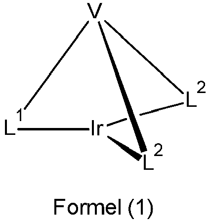
- wobei für die verwendeten Symbole gilt:
- L1
- ist ein Teilligand gemäß einer der folgenden Formel (2a) bis (2d), der über die beiden Gruppen D an das Iridium koordiniert und der über die gestrichelte Bindung an V gebunden ist,

R' ist eine Gruppe der folgenden Formel (3),
R" ist gleich oder verschieden bei jedem Auftreten H, D, F, CN, eine geradkettige Alkylgruppe mit 1 bis 10 C-Atomen, in der auch ein oder mehrere H-Atome durch D oder F ersetzt sein können, oder eine verzweigte oder cyclische Alkylgruppe mit 3 bis 10 C-Atomen, in der auch ein oder mehrere H-Atome durch D oder F ersetzt sein können, oder eine Alkenylgruppe mit 2 bis 10 C-Atomen, in der auch ein oder mehrere H-Atome durch D oder F ersetzt sein können; dabei können auch zwei benachbarte Reste R" bzw. zwei Reste R" an benachbarten Phenylgruppen mitein-ander ein Ringsystem bilden; oder zwei R" an benachbarten Phenylgruppen stehen zusammen für eine Gruppe ausgewählt aus O oder S, so dass die beiden Phenylringe zusammen mit der verbrückenden Gruppe für ein Dibenzofuran oder Dibenzothiophen stehen, und die weiteren R" sind wie vorstehend definiert;
n ist 0, 1, 2, 3, 4 oder 5; - L2
- ist gleich oder verschieden bei jedem Auftreten ein bidentater, monoanionischer Teilligand, der über ein Kohlenstoffatom und ein Stickstoffatom oder über zwei Kohlenstoffatome oder über zwei Stickstoffatome an das Iridium koordiniert und der mit einem oder mehreren Resten R substituiert sein kann;
- V
- ist eine Gruppe der Formel (6b) oder (7b), wobei die gestrichelten Bindungen die Position der Verknüpfung der Teilliganden L1 und L2 darstellen,

- R
- ist bei jedem Auftreten gleich oder verschieden H, D, F, Cl, Br, I, N(R1)2, OR1, SR1, CN, NO2, COOH, C(=O)N(R1)2, Si(R1)3, B(OR1)2, C(=O)R1, P(=O)(R1)2, S(=O)R1, S(=O)2R1, OSO2R1, eine geradkettige Alkylgruppe mit 1 bis 20 C-Atomen oder eine Alkenyl- oder Alkinylgruppe mit 2 bis 20 C-Atomen oder eine verzweigte oder cyclische Alkylgruppe mit 3 bis 20 C-Atomen, wobei die Alkyl-, Alkenyl- oder Alkinylgruppe jeweils mit einem oder mehreren Resten R1 substituiert sein kann und wobei eine oder mehrere nicht benachbarte CH2-Gruppen durch Si(R1)2, C=O, NR1, O, S oder CONR1 ersetzt sein können, oder eine Aryl- oder Heteroarylgruppe mit 5 bis 10 aromatischen Ringatomen, die jeweils durch einen oder mehrere nicht-aromatische Reste R1 substituiert sein kann; dabei können zwei Reste R auch miteinander ein aliphatisches oder heteroaliphatisches Ringsystem bilden;
- R1
- ist bei jedem Auftreten gleich oder verschieden H, D, F, Cl, Br, I, N(R2)2, OR2, SR2, CN, NO2, Si(R2)3, B(OR2)2, C(=O)R2, P(=O)(R2)2, S(=O)R2, S(=O)2R2, OSO2R2, eine geradkettige Alkylgruppe mit 1 bis 20 C-Atomen oder eine Alkenyl- oder Alkinylgruppe mit 2 bis 20 C-Atomen oder eine verzweigte oder cyclische Alkylgruppe mit 3 bis 20 C-Atomen, wobei die Alkyl-, Alkenyl- oder Alkinylgruppe jeweils mit einem oder mehreren Resten R2 substituiert sein kann und wobei eine oder mehrere nicht benachbarte CH2-Gruppen durch Si(R2)2, C=O, NR2, O, S oder CONR2 ersetzt sein können, oder eine Aryl- oder Heteroarylgruppe mit 5 bis 10 aromatischen Ringatomen, die jeweils durch einen oder mehrere Reste R2 substituiert sein kann; dabei können zwei oder mehrere Reste R1 miteinander ein aliphatisches oder heteroaliphatisches Ringsystem bilden;
- R2
- ist bei jedem Auftreten gleich oder verschieden H, D, F oder ein aliphatischer organischer Rest, insbesondere ein Kohlenwasserstoffrest, mit 1 bis 20 C-Atomen, in dem auch ein oder mehrere H-Atome durch F ersetzt sein können;
- dabei können die drei bidentaten Teilliganden L1 und L2 außer durch die Brücke V auch noch durch eine weitere Brücke zu einem Kryptat geschlossen sein;
- dabei ist die folgende Verbindung von der Erfindung ausgenommen:

- Bei dem Liganden handelt es sich erfindungsgemäß somit um einen hexadentaten, tripodalen Liganden mit einem bidentaten Teilliganden L1 und zwei bidentaten Teilliganden L2. Dabei bedeutet bidentat, dass der jeweilige Teilligand im Komplex über zwei Koordinationsstellen an das Iridium koordiniert bzw. bindet. Tripodal bedeutet, dass der Ligand drei Teilliganden aufweist, die an die Brücke V bzw. die Brücke der Formel (6b) bzw. (7b) gebunden sind. Da der Ligand drei bidentate Teilliganden aufweist, ergibt sich insgesamt ein hexadentater Ligand, also ein Ligand, der über sechs Koordinationsstellen an das Iridium koordiniert bzw. bindet. Der Begriff "bidentater Teilligand" bedeutet im Sinne dieser Anmeldung, dass es sich bei L1 bzw. L2 jeweils um einen bidentaten Liganden handeln würde, wenn die Brücke V bzw. die Brücke der Formel (6b) bzw. (7b) nicht vorhanden wäre. Durch die formale Abstraktion eines Wasserstoffatoms von diesem bidentaten Liganden und die Anknüpfung an die Brücke V bzw. die Brücke der Formel (6b) bzw. (7b) ist dieser jedoch kein separater Ligand mehr, sondern ein Teil des so entstehenden hexadentaten Liganden, so dass hierfür der Begriff "Teilligand" verwendet wird.
- Wenn in der vorliegenden Anmeldung die Rede davon ist, dass der Ligand bzw. ein Teilligand an das Iridium koordiniert oder bindet, so bezeichnet dies im Sinne der vorliegenden Anmeldung jede Art der Bindung von dem Liganden bzw. Teilliganden an das Iridium, unabhängig vom kovalenten Anteil der Bindung.
- Wenn zwei Reste R bzw. R1 miteinander ein Ringsystem bilden, so kann dieses mono- oder polycyclisch, aliphatisch oder heteroaliphatisch sein. Dabei können diese Reste, die miteinander ein Ringsystem bilden, benachbart sein, d. h. dass diese Reste an dasselbe Kohlenstoffatom oder an Kohlenstoffatome, die direkt aneinander gebunden sind, gebunden sind, oder sie können weiter voneinander entfernt sein. Bevorzugt ist eine solche Ringbildung bei Resten, die an direkt aneinander gebundene Kohlenstoffatome gebunden sind. Wenn zwei Reste R" in Formel (3) miteinander ein Ringsystem bilden, dann handelt es sich dabei um ein aliphatisches Ringsystem. Bei Ringbildung von zwei Substituenten R" an benachbarten Phenylgruppen entsteht ein Fluoren bzw. ein Phenanthren bzw. ein Triphenylen. Ebenso können, wie vorne beschrieben, zwei R" an benachbarten Phenylgruppen zusammen für eine Gruppe ausgewählt aus O oder S stehen, so dass die beiden Phenylringe zusammen mit der verbrückenden Gruppe für ein Dibenzofuran oder Dibenzothiophen stehen.
- Unter der Formulierung, dass zwei oder mehr Reste miteinander einen Ring bilden können, soll im Rahmen der vorliegenden Beschreibung unter anderem verstanden werden, dass die beiden Reste miteinander durch eine chemische Bindung unter formaler Abspaltung von zwei Wasserstoffatomen verknüpft sind. Dies wird durch das folgende Schema verdeutlicht.

- Weiterhin soll unter der oben genannten Formulierung auch verstanden werden, dass für den Fall, dass einer der beiden Reste Wasserstoff darstellt, der zweite Rest unter Bildung eines Rings an die Position, an die das Wasserstoffatom gebunden war, bindet. Dies soll durch das folgende Schema verdeutlicht werden:

- Weiterhin soll unter der oben genannten Formulierung auch verstanden werden, dass für den Fall, dass die beiden Reste Alkenylgruppen darstellen, die Reste unter Bildung einer ankondensierten Arylgruppe miteinander einen Ring bilden. Analog ist bei einem Aryloxy-Substituenten die Bildung einer ankondensierten Benzofurangruppe und bei einem Arylamino-Substituenten die Bildung einer ankondensierten Indolgruppe möglich. Dies soll durch die folgenden Schemata verdeutlicht werden:


- Unter einer cyclischen Alkyl-, Alkoxy- oder Thioalkoxygruppe im Sinne dieser Erfindung wird eine monocyclische, eine bicyclische oder eine polycyclische Gruppe verstanden.
- Im Rahmen der vorliegenden Erfindung werden unter einer C1-bis C20-Alkylgruppe, in der auch einzelne H-Atome oder CH2-Gruppen durch die oben genannten Gruppen substituiert sein können, beispielsweise die Reste Methyl, Ethyl, n-Propyl, i-Propyl, Cyclopropyl, n-Butyl, i-Butyl, s-Butyl, t-Butyl, Cyclobutyl, 2-Methylbutyl, n-Pentyl, s-Pentyl, t-Pentyl, 2-Pentyl, neo-Pentyl, Cyclopentyl, n-Hexyl, s-Hexyl, t-Hexyl, 2-Hexyl, 3-Hexyl, neo-Hexyl, Cyclohexyl, 1-Methylcyclopentyl, 2-Methylpentyl, n-Heptyl, 2-Heptyl, 3-Heptyl, 4-Heptyl, Cycloheptyl, 1-Methylcyclohexyl, n-Octyl, 2-Ethylhexyl, Cyclooctyl, 1-Bicyclo[2,2,2]octyl, 2-Bicyclo[2,2,2]-octyl, 2-(2,6-Dimethyl)octyl, 3-(3,7-Dimethyl)octyl, Adamantyl, Trifluormethyl, Pentafluorethyl, 2,2,2-Trifluorethyl, 1,1-Dimethyl-n-hex-1-yl-, 1,1-Dimethyl-n-hept-1-yl-, 1,1-Dimethyl-n-oct-1-yl-, 1,1-Dimethyl-n-dec-1 -yl-, 1,1-Dimethyl-n-dodec-1-yl-, 1,1-Dimethyl-n-tetradec-1-yl-, 1,1-Dimethyl-n-hexadec-1-yl-, 1,1-Dimethyl-n-octadec-1-yl-, 1,1-Diethyl-n-hex-1-yl-, 1,1-Diethyl-n-hept-1-yl-, 1,1-Diethyl-n-oct-1-yl-, 1,1-Diethyl-n-dec-1-yl-, 1,1-Diethyl-n-dodec-1-yl-, 1,1-Diethyl-n-tetradec-1-yl-, 1,1-Diethyln-n-hexadec-1-yl-, 1,1-Diethyl-n-octadec-1-yl-, 1-(n-Propyl)-cyclohex-1-yl-, 1-(n-Butyl)-cyclohex-1-yl-, 1-(n-Hexyl)-cyclohex-1-yl-, 1-(n-Octyl)-cyclohex-1-yl- und 1-(n-Decyl)-cyclohex-1-yl- verstanden. Unter einer Alkenylgruppe werden beispielsweise Ethenyl, Propenyl, Butenyl, Pentenyl, Cyclopentenyl, Hexenyl, Cyclohexenyl, Heptenyl, Cycloheptenyl, Octenyl, Cyclooctenyl oder Cyclooctadienyl verstanden. Unter einer Alkinylgruppe werden beispielsweise Ethinyl, Propinyl, Butinyl, Pentinyl, Hexinyl, Heptinyl oder Octinyl verstanden. Unter einer Gruppe OR1 werden beispielsweise Methoxy, Trifluormethoxy, Ethoxy, n-Propoxy, i-Propoxy, n-Butoxy, i-Butoxy, s-Butoxy, t-Butoxy oder 2-Methylbutoxy verstanden.
- Eine Arylgruppe im Sinne dieser Erfindung enthält 6 bis 10 C-Atome; eine Heteroarylgruppe im Sinne dieser Erfindung enthält 2 bis 10 C-Atome und mindestens ein Heteroatom, mit der Maßgabe, dass die Summe aus C-Atomen und Heteroatomen mindestens 5 ergibt. Die Heteroatome sind bevorzugt ausgewählt aus N, O und/oder S. Dabei enthält die Heteroarylgruppe bevorzugt maximal drei Heteroatome. Unter einer Arylgruppe bzw. Heteroarylgruppe wird entweder ein einfacher aromatischer Cyclus bzw. ein einfacher heteroaromatischer Cyclus oder eine kondensierte Aryl- oder Heteroarylgruppe verstanden. Beispiele für erfindungsgemäße Aryl- bzw. Heteroarylgruppen sind Gruppen, die abgeleitet sind von Benzol, Naphthalin, Furan, Benzofuran, Thiophen, Benzothiophen, Pyrrol, Indol, Pyridin, Pyridazin, Pyrimidin, Pyrazin, Chinolin, Isochinolin, Chinazolin, Chinoxalin, Pyrazol, Imidazol, Benzimidazol, Pyridimidazol, Pyrazinimidazol, Oxazol, Benzoxazol, 1,2-Thiazol, 1,3-Thiazol und Benzothiazol.
- Im Folgenden werden die bidentaten Teilliganden L1 beschrieben. Wie oben beschrieben, weist der Teilligand L1 eine Struktur gemäß einer der Formeln (2a) bis (2d) auf und ist mit genau einer Gruppe der Formel (3) substituiert.
- Besonders bevorzugt weist der Teilligand der Formel (2a) bis (2d) eine Struktur gemäß einer der folgenden Formeln (2a') bis (2d') auf,

- Die Reste R am Teilliganden L1 der Formeln (2a) bis (2d) bzw. Formeln (2a') bis (2d') sind bevorzugt ausgewählt aus der Gruppe bestehend aus H, D, CN, OR1, einer geradkettigen Alkylgruppe mit 1 bis 6 C-Atomen, bevorzugt mit 1 bis 3 C-Atomen, oder einer verzweigten oder cyclischen Alkylgruppe mit 3 bis 6 C-Atomen oder einer Alkenylgruppe mit 2 bis 6 C-Atomen, bevorzugt mit 2 bis 4 C-Atomen, die jeweils durch einen oder mehrere Reste R1 substituiert sein kann, oder einer Phenylgruppe, die durch einen oder mehrere nicht-aromatische Reste R1 substituiert sein kann. Dabei können zwei oder mehrere benachbarte Reste R auch miteinander ein Ringsystem bilden.
- Dabei ist der Substituent R, der in ortho-Position sowohl zu dem koordinierenden Atom wie auch zur Verknüpfung zu V bzw. zur Gruppe der Formel (6b) bzw. (7b) gebunden ist, bevorzugt ausgewählt aus der Gruppe bestehend aus H, D, F oder Methyl, besonders bevorzugt H, D oder Methyl und insbesondere H oder D.
- Weiterhin ist es bevorzugt, wenn alle Substituenten R, die in ortho-Position zu R' stehen, für H oder D stehen.
- Wie oben beschrieben, ist R' eine Gruppe der Formel (3), welche in der para-Position mit dem Teilliganden L1 verknüpft ist.
- In einer bevorzugten Ausführungsform der Erfindung ist n = 0, 1 oder 2, bevorzugt 0 oder 1 und ganz besonders bevorzugt 0.
- In einer weiteren bevorzugten Ausführungsform der Erfindung sind beide Substituenten R", welche in den ortho-Positionen zu dem Kohlenstoffatom gebunden sind, mit dem die Gruppe der Formel (3) an den Phenylpyridinliganden gebunden ist, gleich oder verschieden H oder D.
- Bevorzugte Ausführungsformen der Struktur der Formel (3) sind die Strukturen der Formeln (3a) bis (3n),


- Bevorzugte Substituenten R" an den Gruppen der Formel (3) bzw. den bevorzugten Ausführungsformen sind gewählt aus der Gruppe bestehend aus der Gruppe bestehend aus H, D, CN und einer Alkylgruppe mit 1 bis 4 C-Atomen, besonders bevorzugt H, D oder Methyl.
- Im Folgenden werden die bidentaten Teilliganden L2 beschrieben. Wie oben beschrieben koordinieren die Teilliganden L2 an das Iridium über ein Kohlenstoffatom und ein Stickstoffatom oder über zwei Kohlenstoffatome oder über zwei Stickstoffatome. Wenn L2 über zwei Kohlenstoffatome an das Iridium koordiniert, ist eines der beiden Kohlenstoffatome ein Carben-Kohlenstoffatom. Wenn L2 über zwei Stickstoffatome an das Iridium koordiniert, ist eines der beiden Stickstoffatome neutral und das andere anionisch. Weiterhin ist L2 verschieden von L1, da L1 einen Substituenten der Formel (3) aufweist, während L2 nur durch eine kleinere Aryl- oder Heteroarylgruppe substituiert sein kann, nicht jedoch durch eine Biphenylgruppe oder eine Oligophenylengruppe. In einer bevorzugten Ausführungsform der Erfindung sind die beiden Teilliganden L2 identisch.
- Bevorzugt weist mindestens einer der Teilliganden L2 ein Kohlenstoffatom und ein Stickstoffatom oder zwei Kohlenstoffatome als koordinierende Atome auf. Besonders bevorzugt weisen beide Teilliganden L2 ein Kohlenstoffatom und ein Stickstoffatom oder zwei Kohlenstoffatome als koordinierende Atome auf. Ganz besonders bevorzugt weisen beide Teilliganden L2 jeweils ein Kohlenstoffatom und ein Stickstoffatom als koordinierende Atome auf.
- Es ist weiterhin bevorzugt, wenn es sich bei dem Metallacyclus, der aus dem Iridium und dem Teilliganden L2 aufgespannt wird, um einen Fünfring handelt. Dies wird im Folgenden schematisch dargestellt:
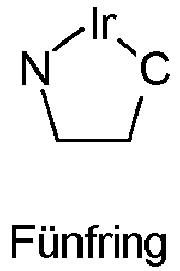
- In einer bevorzugten Ausführungsform der Erfindung weist das Strukturfragment Ir(L2) eine höhere Triplettenergie auf als das Strukturfragment Ir(L1). Dadurch wird erreicht, dass die Emission des Komplexes überwiegend aus dem Strukturfragment Ir(L1) kommt, was zu einer höheren Effizienz führt. Die Triplettenergie wird durch quantenchemische Rechnung bestimmt, wie nachfolgend im Beispielteil allgemein beschrieben. Dabei ist es bevorzugt, wenn die Triplettenergie des Strukturfragments Ir(L2) mindestens 0.025 eV größer ist als die des Strukturfragments Ir(L1), besonders bevorzugt mindestens 0.05 eV größer, ganz besonders bevorzugt mindestens 0.1 eV und noch mehr bevorzugt mindestens 0.2 eV.
- In einer bevorzugten Ausführungsform der Erfindung stehen die Teilliganden L2 gleich oder verschieden bei jedem Auftreten, bevorzugt gleich, für eine Struktur gemäß den folgenden Formeln (L-1), (L-2) oder (L-3),

- wobei die gestrichelte Bindung die Bindung des Teilliganden an die Brücke V, also die Brücke der Formel (5), darstellt und für die weiteren verwendeten Symbole gilt:
- CyC
- ist gleich oder verschieden bei jedem Auftreten eine durch R substituierte oder unsubstituierte Aryl- oder Heteroarylgruppe mit 5 bis 14 aromatischen Ringatomen, welche jeweils über ein Kohlenstoffatom an das Metall koordiniert und welche über eine kovalente Bindung mit CyD verbunden ist;
- CyD
- ist gleich oder verschieden bei jedem Auftreten eine durch R substituierte oder unsubstituierte Heteroarylgruppe mit 5 bis 14 aromatischen Ringatomen, welche über ein Stickstoffatom oder über ein Carben-Kohlenstoffatom an das Metall koordiniert und welche über eine kovalente Bindung mit CyC verbunden ist;
- dabei können mehrere der Substituenten R miteinander ein aliphatisches oder heteroaliphatisches Ringsystem bilden, und CyC und CyD können miteinander durch eine Gruppe gemäß einer der Formeln (17) bis (26) verknüpft sein,


- wobei R1 die oben genannten Bedeutungen aufweist und die gestrichelten Bindungen die Bindungen an CyC bzw. CyD andeuten.
- Dabei koordiniert CyD in (L-1) und (L-2) über ein neutrales Stickstoffatom oder über ein Carben-Kohlenstoffatom und in (L-3) über ein neutrales und ein anionisches Stickstoffatom. Weiterhin koordiniert CyC über ein anionisches Kohlenstoffatom.
- Bevorzugt weisen beide Teilliganden L2 eine Struktur der Formel (L-1) auf, oder beide Teilliganden L2 weisen eine Struktur der Formel (L-2) auf, oder einer der Teilliganden L2 weist eine Struktur der Formel (L-1), und der andere der Teilliganden weist eine Struktur der Formel (L-2) auf, oder beide Teilliganden L2 weisen eine Struktur der Formel (L-3) auf. Bevorzugt sind die beiden Teilliganden L2 gleich.
- In einer bevorzugten Ausführungsform der vorliegenden Erfindung ist CyC eine Aryl- oder Heteroarylgruppe mit 6 bis 13 aromatischen Ringatomen, besonders bevorzugt mit 6 bis 10 aromatischen Ringatomen, ganz besonders bevorzugt mit 6 aromatischen Ringatomen, welche über ein Kohlenstoffatom an das Metall koordiniert, welche mit einem oder mehreren Resten R substituiert sein kann und welche über eine kovalente Bindung mit CyD verbunden ist.
- Bevorzugte Ausführungsformen der Gruppe CyC sind die Strukturen der folgenden Formeln (CyC-1) bis (CyC-19), wobei die Gruppe CyC jeweils an der durch # gekennzeichneten Position an CyD bindet und an der durch * gekennzeichneten Position an das Iridium koordiniert,


- wobei R die oben genannten Bedeutungen aufweist und für die weiteren verwendeten Symbole gilt:
- X
- ist bei jedem Auftreten gleich oder verschieden CR oder N mit der Maßgabe, dass maximal zwei Symbole X pro Cyclus für N stehen;
- W
- ist bei jedem Auftreten gleich oder verschieden NR, O oder S;
- mit der Maßgabe, dass, wenn die Brücke V bzw. die Brücke der Formel (6b) bzw. (7b) an CyC gebunden ist, ein Symbol X für C steht und die Brücke der Formel (6b) bzw. (7b) an dieses Kohlenstoffatom gebunden ist. Wenn die Gruppe CyC an die Brücke der Formel (6b) bzw. (7b) gebunden ist, so erfolgt die Bindung bevorzugt über die mit "o" markierte Position der oben abgebildeten Formeln, so dass dann bevorzugt das mit "o" markierte Symbol X für C steht. Die oben abgebildeten Strukturen, die kein mit "o" markiertes Symbol X enthalten, sind bevorzugt nicht direkt an die Brücke V bzw. die Brücke der Formel (6b) bzw. (7b) gebunden, da eine solche Bindung an die Brücke aus sterischen Gründen nicht vorteilhaft ist.
- Bevorzugt stehen insgesamt maximal zwei Symbole X in CyC für N, besonders bevorzugt steht maximal ein Symbol X in CyC für N, ganz besonders bevorzugt stehen alle Symbole X für CR, mit der Maßgabe, dass, wenn die Brücke V bzw. die Brücke der Formel (6b) bzw. (7b) an CyC gebunden ist, ein Symbol X für C steht und die Brücke V bzw. die Brücke der Formel (6b) bzw. (7b) an dieses Kohlenstoffatom gebunden ist.
- Besonders bevorzugte Gruppen CyC sind die Gruppen der folgenden Formeln (CyC-1 a) bis (CyC-20a),


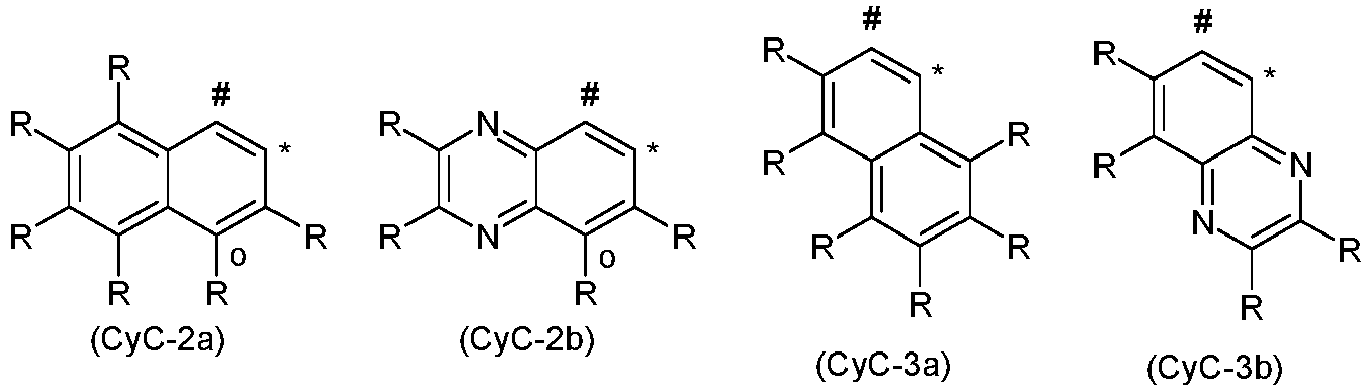


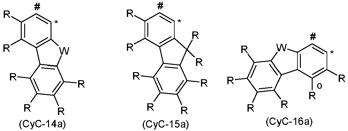

- Bevorzugte Gruppen unter den Gruppen (CyC-1) bis (CyC-19) sind die Gruppen (CyC-1), (CyC-3), (CyC-8), (CyC-10), (CyC-12), (CyC-13) und (CyC-16), und besonders bevorzugt sind die Gruppen (CyC-1 a), (CyC-3a), (CyC-8a), (CyC-10a), (CyC-12a), (CyC-13a) und (CyC-16a).
- In einer weiteren bevorzugten Ausführungsform der Erfindung ist CyD eine Heteroarylgruppe 5 bis 13 aromatischen Ringatomen, besonders bevorzugt mit 6 bis 10 aromatischen Ringatomen, welche über ein neutrales Stickstoffatom oder über ein Carben-Kohlenstoffatom an das Metall koordiniert und welche mit einem oder mehreren Resten R substituiert sein kann und welche über eine kovalente Bindung mit CyC verbunden ist.
- Bevorzugte Ausführungsformen der Gruppe CyD sind die Strukturen der folgenden Formeln (CyD-1) bis (CyD-14), wobei die Gruppe CyD jeweils an der durch # gekennzeichneten Position an CyC bindet und an der durch * gekennzeichneten Position an das Iridium koordiniert,


- Dabei koordinieren die Gruppen (CyD-1) bis (CyD-4) und (CyD-7) bis (CyD-12) über ein neutrales Stickstoffatom und (CyD-5) und (CyD-6) über ein Carben-Kohlenstoffatom an das Iridium. Die Gruppen (CyD-13) und (CyD-14) koordinieren über ein anionisches Stickstoffatom an das Iridium.
- Bevorzugt stehen insgesamt maximal zwei Symbole X in CyD für N, besonders bevorzugt steht maximal ein Symbol X in CyD für N, insbesondere bevorzugt stehen alle Symbole X für CR, mit der Maßgabe, dass, wenn die Brücke der Formel (6b) bzw. (7b) an CyD gebunden ist, ein Symbol X für C steht und die Brücke der Formel (6b) bzw. (7b) an dieses Kohlenstoffatom gebunden ist.
- Besonders bevorzugte Gruppen CyD sind die Gruppen der folgenden Formeln (CyD-1 a) bis (CyD-14b),


- Bevorzugte Gruppen unter den Gruppen (CyD-1) bis (CyD-12) sind die Gruppen (CyD-1), (CyD-2), (CyD-3), (CyD-4), (CyD-5) und (CyD-6), insbesondere (CyD-1), (CyD-2) und (CyD-3), und besonders bevorzugt sind die Gruppen (CyD-1 a), (CyD-2a), (CyD-3a), (CyD-4a), (CyD-5a) und (CyD-6a), insbesondere (CyD-1 a), (CyD-2a) und (CyD-3a).
- In einer bevorzugten Ausführungsform der vorliegenden Erfindung ist CyC eine Aryl- oder Heteroarylgruppe mit 6 bis 13 aromatischen Ringatomen, und gleichzeitig ist CyD eine Heteroarylgruppe mit 5 bis 13 aromatischen Ringatomen. Besonders bevorzugt ist CyC eine Aryl- oder Heteroarylgruppe mit 6 bis 10 aromatischen Ringatomen, und gleichzeitig ist CyD eine Heteroarylgruppe mit 5 bis 10 aromatischen Ringatomen. Ganz besonders bevorzugt ist CyC eine Aryl- oder Heteroarylgruppe mit 6 aromatischen Ringatomen und CyD eine Heteroarylgruppe mit 6 bis 10 aromatischen Ringatomen. Dabei können CyC und CyD mit einem oder mehreren Resten R substituiert sein.
- Die oben genannten bevorzugten Gruppen (CyC-1) bis (CyC-20) und (CyD-1) bis (CyD-12) können beliebig miteinander kombiniert werden, sofern mindestens eine der Gruppen CyC bzw. CyD eine geeignete Anknüpfungsstelle an die Brücke V bzw. die Brücke der Formel (6b) bzw. (7b) aufweist, wobei geeignete Anknüpfungsstellen in den oben genannten Formeln mit "o" gekennzeichnet sind.
- Insbesondere bevorzugt ist es, wenn die oben als besonders bevorzugt genannten Gruppen CyC und CyD, also die Gruppen der Formeln (CyC-1 a) bis (CyC-20a) und die Gruppen der Formeln (CyD1-a) bis (CyD-14b) miteinander kombiniert werden, sofern mindestens eine der bevorzugten Gruppen CyC bzw. CyD eine geeignete Anknüpfungsstelle an die Brücke V bzw. die Brücke der Formel (6b) bzw. (7b) aufweist, wobei geeignete Anknüpfungsstellen in den oben genannten Formeln mit "o" gekennzeichnet sind. Kombinationen, in denen weder CyC noch CyD eine solche geeignete Anknüpfungsstelle für die Brücke der Formel (6b) bzw. (7b) aufweist, sind daher nicht bevorzugt.
- Ganz besonders bevorzugt ist es, wenn eine der Gruppen (CyC-1), (CyC-3), (CyC-8), (CyC-10), (CyC-12), (CyC-13) und (CyC-16), insbesondere die Gruppen (CyC-1 a), (CyC-3a), (CyC-8a), (CyC-10a), (CyC-12a), (CyC-13a) und (CyC-16a), mit einer der Gruppen (CyD-1), (CyD-2) und (CyD-3), insbesondere mit einer der Gruppen (CyD-1 a), (CyD-2a) und (CyD-3a), kombiniert wird.
- Bevorzugte Teilliganden (L-1) sind die Strukturen der Formeln (L-1-1) und (L-1-2), und bevorzugte Teilliganden (L-2) sind die Strukturen der Formeln (L-2-1) bis (L-2-4),

- Besonders bevorzugte Teilliganden (L-1) sind die Strukturen der Formeln (L-1-1a) und (L-1-2b), und besonders bevorzugte Teilliganden (L-2) sind die Strukturen der Formeln (L-2-1 a) bis (L-2-4a),
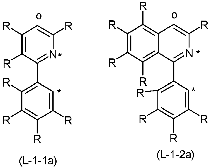

- Wenn zwei Reste R, von denen einer an CyC und der andere an CyD gebunden sind, miteinander ein aromatisches Ringsystem bilden, können sich überbrückte Teilliganden ergeben, wobei manche dieser überbrückten Teilliganden dann insgesamt eine einzige größere Heteroarylgruppe darstellen, wie beispielsweise Benzo[h]chinolin, etc.. Die Ringbildung zwischen den Substituenten an CyC und CyD erfolgt dabei wie oben beschrieben durch eine Gruppe gemäß einer der oben abgebildeten Formeln (17) bis (26). Dabei können die unsymmetrischen der oben genannten Gruppen in jeder der beiden Möglichkeiten eingebaut werden. So kann beispielsweise bei der Gruppe der Formel (26) das Sauerstoffatom an die Gruppe CyC und die Carbonylgruppe an die Gruppe CyD binden, oder das Sauerstoffatom kann an die Gruppe CyD und die Carbonylgruppe an die Gruppe CyC binden.
- Dabei ist die Gruppe der Formel (23) besonders dann bevorzugt, wenn sich dadurch die Ringbildung zu einem Sechsring ergibt, wie beispielsweise unten durch die Formeln (L-21) und (L-22) dargestellt.
- Bevorzugte Liganden, die durch Ringbildung zweier Reste R an den unterschiedlichen Cyclen entstehen, sind die im Folgenden aufgeführten Strukturen der Formeln (L-3) bis (L-30),


- In einer bevorzugten Ausführungsform der Teilliganden der Formeln (L-3) bis (L-30) steht insgesamt ein Symbol X für N, und die anderen Symbole X stehen für CR, oder alle Symbole X stehen für CR.
- In einer weiteren Ausführungsform der Erfindung ist es bevorzugt, falls in den Gruppen (CyC-1) bis (CyC-20) oder (CyD-1) bis (CyD-14) oder in den Teilliganden (L-3) bis (L-30) eines der Atome X für N steht, wenn benachbart zu diesem Stickstoffatom eine Gruppe R als Substituent gebunden ist, welche ungleich Wasserstoff oder Deuterium ist. Dies gilt analog für die bevorzugten Strukturen (CyC-1 a) bis (CyC-20a) oder (CyD-1 a) bis (CyD-14b), in denen bevorzugt benachbart zu einem nicht koordinierenden Stickstoffatom eine Gruppe R als Substituent gebunden ist, welche ungleich Wasserstoff oder Deuterium ist.
- Dabei ist dieser Substituent R bevorzugt eine Gruppe, ausgewählt aus CF3, OCF3, Alkylgruppen mit 1 bis 10 C-Atomen, insbesondere verzweigten oder cyclischen Alkylgruppen mit 3 bis 10 C-Atomen, OR1, wobei R1 für eine Alkylgruppe mit 1 bis 10 C-Atomen, insbesondere eine verzweigte oder cyclische Alkylgruppe mit 3 bis 10 C-Atomen steht, Dialkylaminogruppen mit 2 bis 10 C-Atomen oder Aryl- bzw. Heteroarylgruppen mit 5 bis 10 aromatischen Ringatomen. Es handelt sich bei diesen Gruppen um sterisch anspruchsvolle Gruppen. Weiterhin bevorzugt kann dieser Rest R auch mit einem benachbarten Rest R einen aliphatischen oder heteroaliphatischen Cyclus bilden.
- Ein weiterer geeigneter bidentater Teilligand ist ein Teilligand der folgenden Formel (L-31) oder (L-32),

- X
- ist bei jedem Auftreten gleich oder verschieden CR oder N mit der Maßgabe, dass maximal ein Symbol X pro Cyclus für N steht.
- In einer bevorzugten Ausführungsform der Erfindung stehen im Teilliganden der Formel (L-31) und (L-32) insgesamt 0, 1 oder 2 der Symbole X und, falls vorhanden, Y für N. Besonders bevorzugt stehen insgesamt 0 oder 1 der Symbole X und, falls vorhanden, Y für N.
- Bevorzugte Ausführungsformen der Formeln (L-31) und (L-32) sind die Strukturen der folgenden Formeln (L-33a) bis (L-34d),


- In einer bevorzugten Ausführungsform der Erfindung steht die Gruppe X, die in ortho-Position zur Koordination an das Metall vorliegt, für CR. Dabei ist in dieser Rest R, der in ortho-Position zur Koordination an das Metall gebunden ist, bevorzugt ausgewählt aus der Gruppe bestehend aus H, D, F und Methyl.
- In einer weiteren Ausführungsform der Erfindung ist es bevorzugt, falls eines der Atome X oder, wenn vorhanden, Y für N steht, wenn benachbart zu diesem Stickstoffatom eine Gruppe R als Substituent gebunden ist, welche ungleich H oder D ist. Dabei ist dieser Substituent R bevorzugt eine Gruppe, ausgewählt aus CF3, OCF3, Alkylgruppen mit 1 bis 10 C-Atomen, insbesondere verzweigten oder cyclischen Alkylgruppen mit 3 bis 10 C-Atomen, OR1, wobei R1 für eine Alkylgruppe mit 1 bis 10 C-Atomen, insbesondere eine verzweigte oder cyclische Alkylgruppe mit 3 bis 10 C-Atomen steht, Dialkylaminogruppen mit 2 bis 10 C-Atomen oder Aryl- bzw. Heteroarylgruppen mit 5 bis 10 aromatischen Ringatomen. Es handelt sich bei diesen Gruppen um sterisch anspruchsvolle Gruppen. Weiterhin bevorzugt kann dieser Rest R auch mit einem benachbarten Rest R einen aliphatischen oder heteroaliphatischen Cyclus bilden.
- Im Folgenden werden bevorzugte Substituenten beschrieben, wie sie an den oben beschriebenen Teilliganden L1 und/oder L2 vorliegen können.
- In einer weiteren Ausführungsform der Erfindung enthält der erfindungsgemäße Metallkomplex zwei Substituenten R oder zwei Substituenten R1, die an benachbarte Kohlenstoffatome gebunden sind und die miteinander einen aliphatischen Ring gemäß einer der nachfolgend beschriebenen Formeln bilden. Dabei können die beiden Substituenten R, die diesen aliphatischen Ring bilden, an einem oder mehreren der bidentaten Teilliganden vorliegen. Der aliphatische Ring, der durch die Ringbildung von zwei Substituenten R miteinander oder von zwei Substituenten R1 miteinander gebildet wird, wird bevorzugt durch eine der folgenden Formeln (27) bis (33) beschrieben,


- wobei R1 und R2 die oben genannten Bedeutungen aufweisen, die gestrichelten Bindungen die Verknüpfung der beiden Kohlenstoffatome im Liganden andeuten und weiterhin gilt:
- A1, A3
- ist gleich oder verschieden bei jedem Auftreten C(R3)2, O, S, NR3 oder C(=O);
- A2
- ist C(R1)2, O, S, NR3 oder C(=O);
- G
- ist eine Alkylengruppe mit 1, 2 oder 3 C-Atomen, welche mit einem oder mehreren Resten R2 substituiert sein kann, -CR2=CR2- oder eine ortho-verknüpfte Arylen- oder Heteroarylengruppe mit 5 oder 6 aromatischen Ringatomen, welche durch einen oder mehrere Reste R2 substituiert sein kann;
- R3
- ist gleich oder verschieden bei jedem Auftreten H, F, OR2, eine geradkettige Alkylgruppe mit 1 bis 10 C-Atomen, eine verzweigte oder cyclische Alkylgruppe mit 3 bis 10 C-Atomen, wobei die Alkylgruppe jeweils mit einem oder mehreren Resten R2 substituiert sein kann, wobei eine oder mehrere nicht benachbarte CH2-Gruppen durch R2C=CR2, C=C, Si(R2)2, C=O, NR2, O, S oder CONR2 ersetzt sein können, oder eine Aryl- oder Heteroarylgruppe mit 5 oder 6 aromatischen Ringatomen, das jeweils durch einen oder mehrere Reste R2 substituiert sein kann; dabei können zwei Reste R3, welche an dasselbe Kohlenstoffatom gebunden sind, miteinander ein aliphatisches Ringsystem bilden und so ein Spirosystem aufspannen; weiterhin kann R3 mit einem benachbarten Rest R oder R1 ein aliphatisches Ringsystem bilden;
- mit der Maßgabe, dass in diesen Gruppen nicht zwei Heteroatome direkt aneinander gebunden sind und nicht zwei Gruppen C=O direkt aneinander gebunden sind.
- In den oben abgebildeten Strukturen der Formeln (27) bis (33) sowie den weiteren als bevorzugt genannten Ausführungsformen dieser Strukturen wird formal eine Doppelbindung zwischen den zwei Kohlenstoffatomen abgebildet. Dies stellt eine Vereinfachung der chemischen Struktur dar, wenn diese beiden Kohlenstoffatome in ein aromatisches oder heteroaromatisches System eingebunden sind und somit die Bindung zwischen diesen beiden Kohlenstoffatomen formal zwischen dem Bindungsgrad einer Einfachbindung und dem einer Doppelbindung liegt. Das Einzeichnen der formalen Doppelbindung ist somit nicht limitierend für die Struktur auszulegen, sondern es ist für den Fachmann offensichtlich, dass es sich hier um eine aromatische Bindung handelt.
- Wenn benachbarte Reste in den erfindungsgemäßen Strukturen ein aliphatisches Ringsystem bilden, dann ist es bevorzugt, wenn dieses keine aziden benzylischen Protonen aufweist. Unter benzylischen Protonen werden Protonen verstanden, die an ein Kohlenstoffatom binden, welches direkt an den Liganden gebunden sind. Dies kann dadurch erreicht werden, dass die Kohlenstoffatome des aliphatischen Ringsystems, die direkt an eine Aryl- oder Heteroarylgruppe binden, vollständig substituiert sind und keine Wasserstoffatome gebunden enthalten. So wird die Abwesenheit von aziden benzylischen Protonen in den Formeln (27) bis (29) dadurch erreicht, dass A1 und A3, wenn diese für C(R3)2 stehen, so definiert sind, dass R3 ungleich Wasserstoff ist. Dies kann weiterhin auch dadurch erreicht werden, dass die Kohlenstoffatome des aliphatischen Ringsystems, die direkt an eine Aryl- oder Heteroarylgruppe binden, die Brückenköpfe einer bi- oder polycyclischen Struktur sind. Die an Brückenkopfkohlenstoffatome gebundenen Protonen sind aufgrund der räumlichen Struktur des Bi- oder Polycyclus wesentlich weniger azide als benzylische Protonen an Kohlenstoffatomen, die nicht in einer bi- oder polycyclischen Struktur gebunden sind, und werden im Sinne der vorliegenden Erfindung als nicht-azide Protonen angesehen. So wird die Abwesenheit von aziden benzylischen Protonen ist in Formeln (30) bis (33) dadurch erreicht, dass es sich dabei um eine bicyclische Struktur handelt, wodurch R1, wenn es für H steht, deutlich weniger azide als benzylische Protonen, da das korrespondierende Anion der bicyclischen Struktur nicht mesomeriestabilisiert ist. Auch wenn R1 in Formeln (30) bis (33) für H steht, handelt es sich dabei daher um ein nicht-azides Proton im Sinne der vorliegenden Anmeldung.
- In einer bevorzugten Ausführungsform der Erfindung ist R3 ungleich H.
- In einer bevorzugten Ausführungsform der Struktur gemäß Formel (27) bis (33) steht maximal eine der Gruppen A1, A2 und A3 für ein Heteroatom, insbesondere für O oder NR3, und die anderen Gruppen stehen für C(R3)2 bzw. C(R1)2 oder A1 und A3 stehen gleich oder verschieden bei jedem Auftreten für O oder NR3 und A2 steht für C(R1)2. In einer besonders bevorzugten Ausführungsform der Erfindung stehen A1 und A3 gleich oder verschieden bei jedem Auftreten für C(R3)2 und A2 steht für C(R1)2 und besonders bevorzugt für C(R3)2 oder CH2.
- Bevorzugte Ausführungsformen der Formel (27) sind somit die Strukturen der Formel (27-A), (27-B), (27-C) und (27-D), und eine besonders bevorzugte Ausführungsform der Formel (27-A) sind die Strukturen der Formel (27-E) und (27-F),


- Bevorzugte Ausführungsformen der Formel (28) sind die Strukturen der folgenden Formeln (28-A) bis (28-F),


- Bevorzugte Ausführungsformen der Formel (29) sind die Strukturen der folgenden Formeln (29-A) bis (29-E),


- In einer bevorzugten Ausführungsform der Struktur gemäß Formel (30) stehen die Reste R1, die an den Brückenkopf gebunden sind, für H, D, F oder CH3. Weiterhin bevorzugt steht A2 für C(R1)2 oder O, und besonders bevorzugt für C(R3)2. Bevorzugte Ausführungsformen der Formel (48) sind somit eine Strukturen der Formel (30-A) und (30-B), und eine besonders bevorzugte Ausführungsform der Formel (30-A) ist eine Struktur der Formel (30-C),

- In einer bevorzugten Ausführungsform der Struktur gemäß Formel (31), (32) und (33) stehen die Reste R1, die an den Brückenkopf gebunden sind, für H, D, F oder CH3. Weiterhin bevorzugt steht A2 für C(R1)2. Bevorzugte Ausführungsformen der Formel (31), (32) und (33) sind somit die Strukturen der Formeln (31-A), (32-A) und (33-A),

- Weiterhin bevorzugt steht die Gruppe G in den Formeln (30), (30-A), (30-B), (30-C), (31), (31-A), (32), (32-A), (33) und (33-A) für eine 1,2-Ethylengruppe, welche mit einem oder mehreren Resten R2 substituiert sein kann, wobei R2 bevorzugt gleich oder verschieden bei jedem Auftreten für H oder eine Alkylgruppe mit 1 bis 4 C-Atomen steht, oder eine ortho-Arylengruppe mit 6 bis 10 C-Atomen, welche mit einem oder mehreren Resten R2 substituiert sein kann, bevorzugt aber unsubstituiert ist, insbesondere eine ortho-Phenylengruppe, welche mit einem oder mehreren Resten R2 substituiert sein kann, bevorzugt aber unsubstituiert ist.
- In einer weiteren bevorzugten Ausführungsform der Erfindung steht R3 in den Gruppen der Formel (27) bis (33) und in den bevorzugten Ausführungsformen gleich oder verschieden bei jedem Auftreten für F, eine geradkettige Alkylgruppe mit 1 bis 10 C-Atomen oder eine verzweigte oder cyclische Alkylgruppe mit 3 bis 20 C-Atomen, wobei jeweils eine oder mehrere nicht benachbarte CH2-Gruppen durch R2C=CR2 ersetzt sein können und ein oder mehrere H-Atome durch D oder F ersetzt sein können, oder Phenylgruppe, die durch einen oder mehrere Reste R2 substituiert sein kann; dabei können zwei Reste R3, welche an dasselbe Kohlenstoffatom gebunden sind, miteinander ein aliphatisches oder aromatisches Ringsystem bilden und so ein Spirosystem aufspannen; weiterhin kann R3 mit einem benachbarten Rest R oder R1 ein aliphatisches Ringsystem bilden.
- In einer besonders bevorzugten Ausführungsform der Erfindung steht R3 in den Gruppen der Formeln (27) bis (33) und in den bevorzugten Ausführungsformen gleich oder verschieden bei jedem Auftreten für F, eine geradkettige Alkylgruppe mit 1 bis 3 C-Atomen, insbesondere Methyl, oder eine Phenylgruppe, die durch einen oder mehrere Reste R2 substituiert sein kann, bevorzugt aber unsubstituiert ist; dabei können zwei Reste R3, welche an dasselbe Kohlenstoffatom gebunden sind, miteinander ein aliphatisches oder aromatisches Ringsystem bilden und so ein Spirosystem aufspannen; weiterhin kann R3 mit einem benachbarten Rest R oder R1 ein aliphatisches Ringsystem bilden.
- Beispiele für besonders geeignete Gruppen der Formel (27) sind die im Folgenden aufgeführten Strukturen:


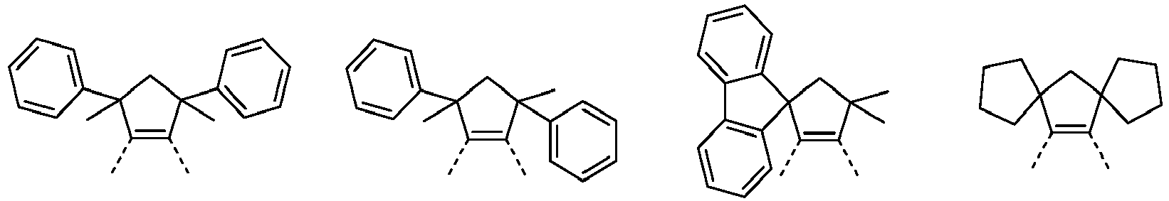


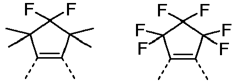


- Beispiele für besonders geeignete Gruppen der Formel (28) sind die im Folgenden aufgeführten Strukturen:


- Beispiele für besonders geeignete Gruppen der Formel (29), (32) und (33) sind die im Folgenden aufgeführten Strukturen:

- Beispiele für besonders geeignete Gruppen der Formel (30) sind die im Folgenden aufgeführten Strukturen:
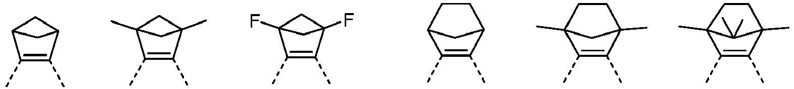

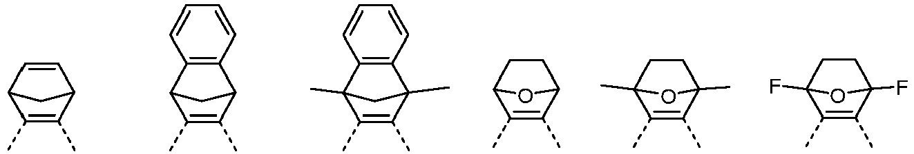

- Beispiele für besonders geeignete Gruppen der Formel (31) sind die im Folgenden aufgeführten Strukturen:

- Wenn in den bidentaten Teilliganden L1 bzw. L2 Reste R gebunden sind, so sind diese Reste R bei jedem Auftreten gleich oder verschieden bevorzugt ausgewählt aus der Gruppe bestehend aus H, D, F, Br, I, N(R1)2, CN, Si(R1)3, B(OR1)2, C(=O)R1, einer geradkettigen Alkylgruppe mit 1 bis 10 C-Atomen oder einer Alkenylgruppe mit 2 bis 10 C-Atomen oder einer verzweigten oder cyclischen Alkylgruppe mit 3 bis 10 C-Atomen, wobei die Alkyl oder Alkenylgruppe jeweils mit einem oder mehreren Resten R1 substituiert sein kann, oder einer Phenylgruppe, die durch einen oder mehrere nicht-aromatische Reste R1 substituiert sein kann, oder einer Heteroarylgruppe mit 5 oder 6 aromatischen Ringatomen, die durch einen oder mehrere nicht-aromatische Reste R1 substituiert sein kann; dabei können zwei benachbarte Rest R oder R mit R1 auch miteinander ein mono- oder polycyclisches, aliphatisches Ringsystem bilden. Besonders bevorzugt sind diese Reste R bei jedem Auftreten gleich oder verschieden ausgewählt aus der Gruppe bestehend aus H, D, F, N(R1)2, einer geradkettigen Alkylgruppe mit 1 bis 6 C-Atomen oder einer verzweigten oder cyclischen Alkylgruppe mit 3 bis 10 C-Atomen, wobei ein oder mehrere H-Atome durch D oder F ersetzt sein können, oder einer Phenylgruppe, die durch einen oder mehrere nicht-aromatische Reste R1 substituiert sein kann, oder einer Heteroarylgruppe mit 6 aromatischen Ringatomen, die durch einen oder mehrere nicht-aromatische Reste R1 substituiert sein kann; dabei können zwei benachbarte Reste R oder R mit R1 auch miteinander ein mono- oder polycyclisches, aliphatisches Ringsystem bilden.
- Bevorzugte Reste R1, die an R gebunden sind, sind bei jedem Auftreten gleich oder verschieden H, D, F, N(R2)2, CN, eine geradkettige Alkylgruppe mit 1 bis 10 C-Atomen oder eine Alkenylgruppe mit 2 bis 10 C-Atomen oder eine verzweigte oder cyclische Alkylgruppe mit 3 bis 10 C-Atomen, wobei die Alkylgruppe jeweils mit einem oder mehreren Resten R2 substituiert sein kann, oder eine Phenylgruppe, die durch einen oder mehrere Reste R2 substituiert sein kann, oder eine Heteroarylgruppe mit 5 oder 6 aromatischen Ringatomen, die durch einen oder mehrere Reste R2 substituiert sein kann; dabei können zwei oder mehrere benachbarte Reste R1 miteinander ein mono- oder polycyclisches, aliphatisches Ringsystem bilden. Besonders bevorzugte Reste R1, die an R gebunden sind, sind bei jedem Auftreten gleich oder verschieden H, F, CN, eine geradkettige Alkylgruppe mit 1 bis 5 C-Atomen oder eine verzweigte oder cyclische Alkylgruppe mit 3 bis 5 C-Atomen, die jeweils mit einem oder mehreren Resten R2 substituiert sein kann, oder eine Phenylgruppe, die durch einen oder mehrere Reste R2 substituiert sein kann, oder eine Heteroarylgruppe mit 5 oder 6 aromatischen Ringatomen, die durch einen oder mehrere Reste R2 substituiert sein kann; dabei können zwei oder mehrere benachbarte Reste R1 miteinander ein mono- oder polycyclisches, aliphatisches Ringsystem bilden.
- Bevorzugte Reste R2 sind bei jedem Auftreten gleich oder verschieden H, F oder ein aliphatischer Kohlenwasserstoffrest mit 1 bis 5 C-Atomen oder ein aromatischer Kohlenwasserstoffrest mit 6 bis 12 C-Atomen; dabei können zwei oder mehrere Substituenten R2 auch miteinander ein mono- oder polycyclisches, aliphatisches Ringsystem bilden.
- Die oben genannten bevorzugten Ausführungsformen sind beliebig innerhalb der Grenzen des Anspruches 1 miteinander kombinierbar. In einer besonders bevorzugten Ausführungsform der Erfindung gelten die oben genannten bevorzugten Ausführungsformen gleichzeitig.
- Beispiele für geeignete erfindungsgemäße Strukturen sind die nachfolgend abgebildeten Verbindungen.


1 2 

3 4 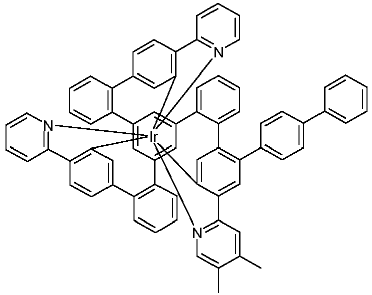

5 6 

7 8 

9 10 

11 12 

13 14 

15 16 

17 18 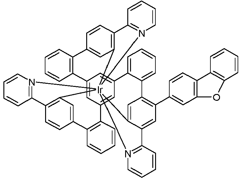
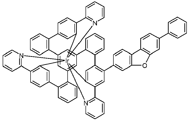
19 20 

21 22 

23 24 

25 26 

29 30 

31 32 

33 34 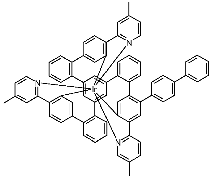

35 36 

37 38 

39 40 

41 42 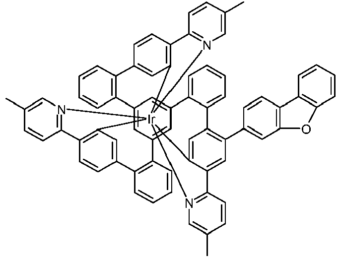

43 44 

45 46 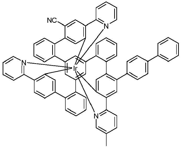

51 52 
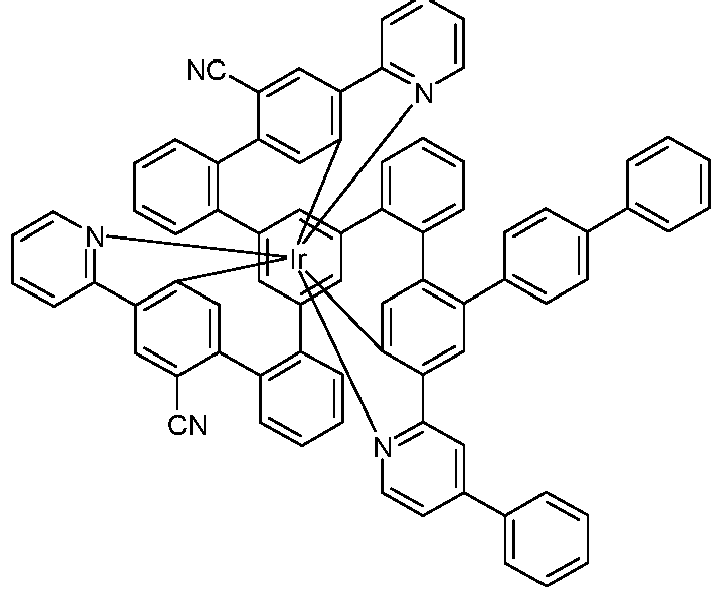
53 54 

60 61 

63 64 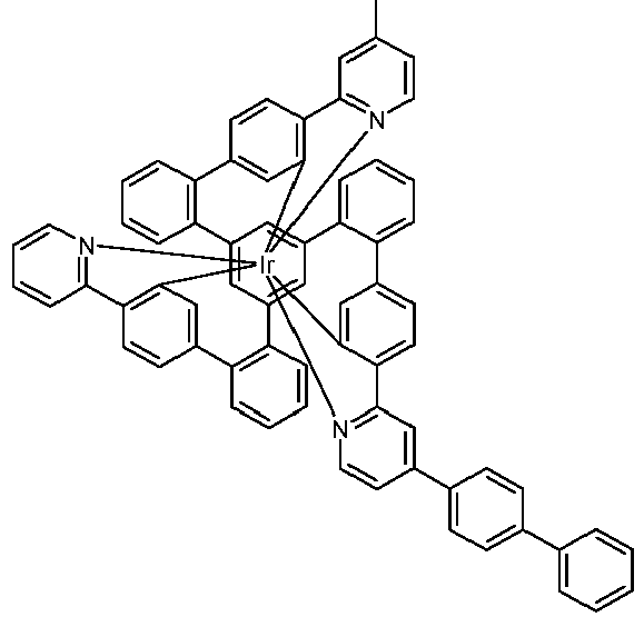

84 86 
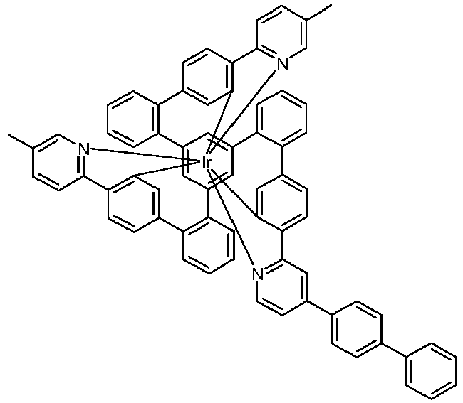
87 88 
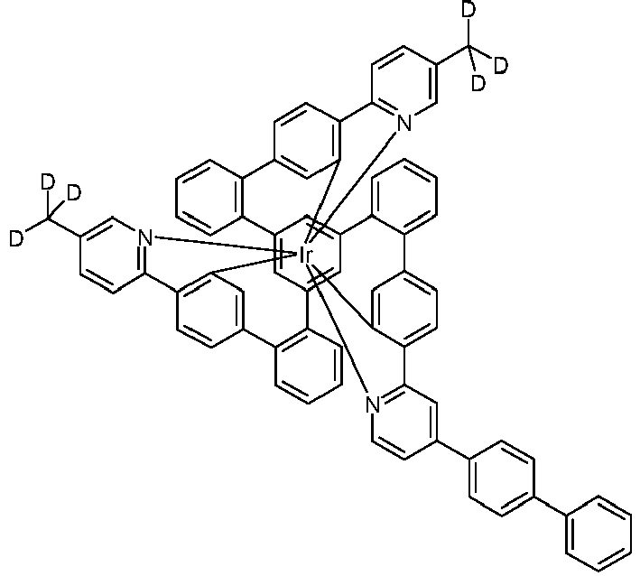
89 90 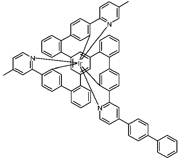

91 92 

93 94 

95 96 

101 102 

103 104 

105 106 
114 

117 118 

119 120 

121 122 

123 124 

125 126 

129 130 

131 132 

133 134 

135 136 

137 138 
139 
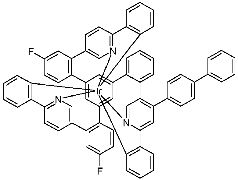
141 142 

143 144 

145 146 

147 148 

149 150 
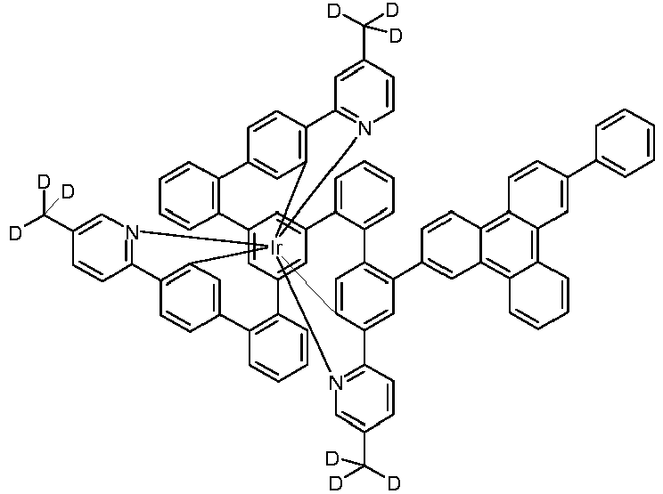
151 152 
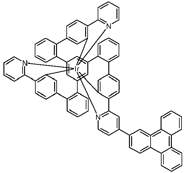
153 154 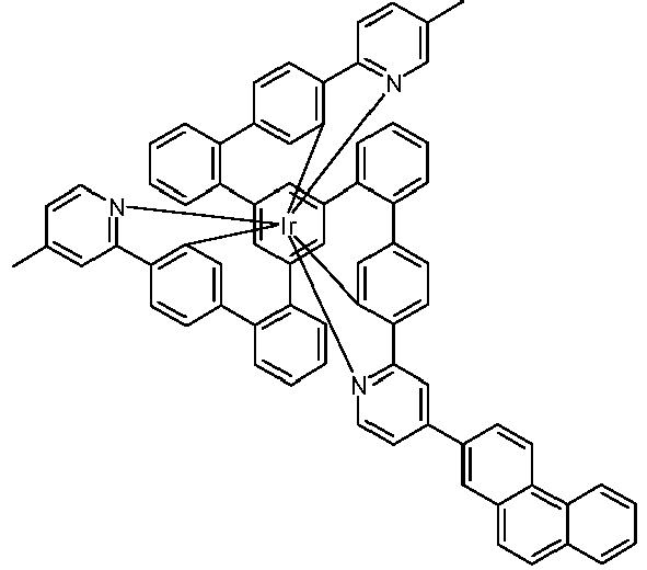
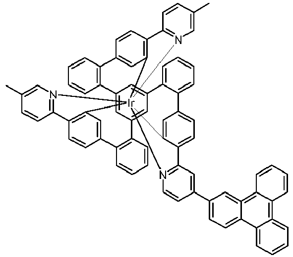
155 156 

157 158 

159 160 
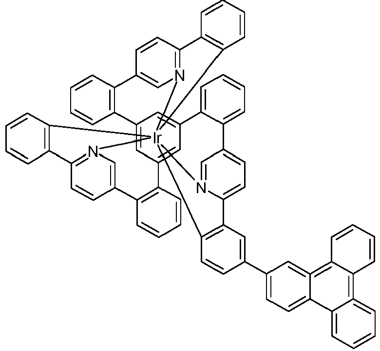
161 162 

163 164 

165 166 

167 168 

169 170 

171 172 

173 174 

175 176 

177 178 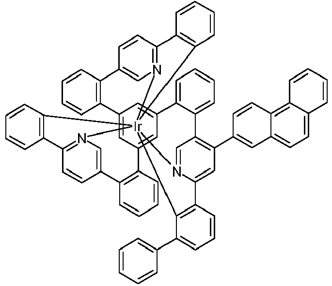

179 180 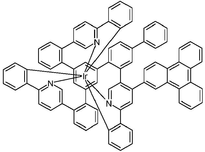

181 182 
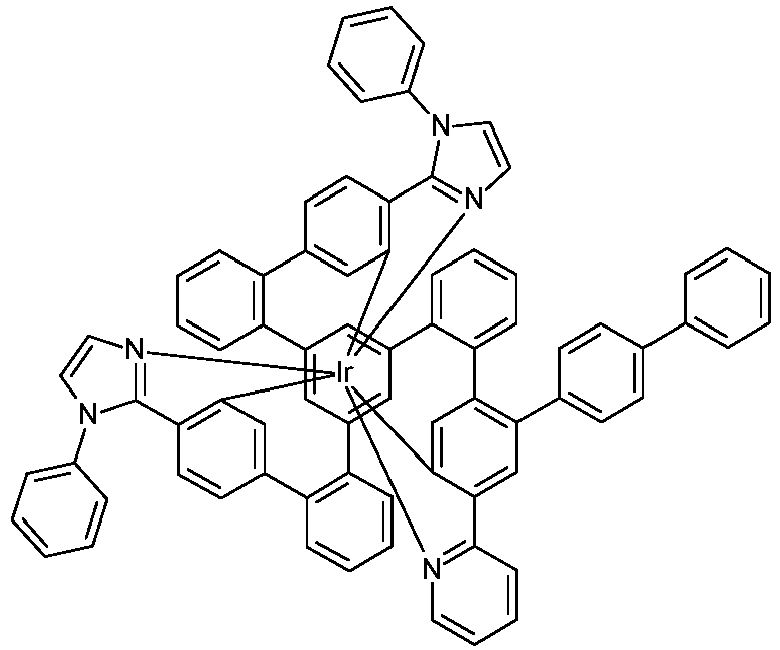
183 184 

185 186 

187 188 

189 190 

192 192 
193 

194 196 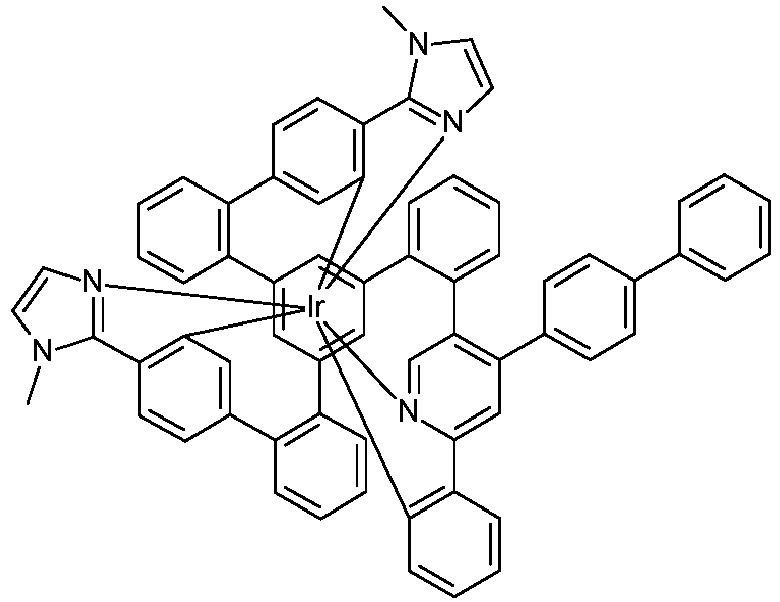

197 198 

199 200 

201 202 

203 204 

205 206 

207 208 

209 210 

211 212 

213 214 

217 218 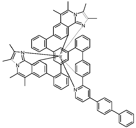

219 220 
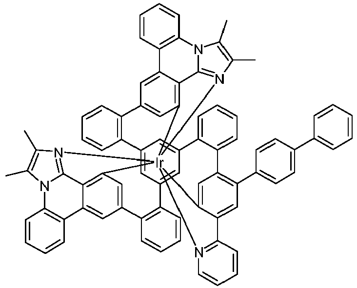
221 222 

223 224 

225 226 
227 228 

229 230 

231 232 
233 234 

235 236 

237 238 

239 240 

241 242 

243 244 

245 246 

247 248 
249 250 

251 252 

253 254 
255 256 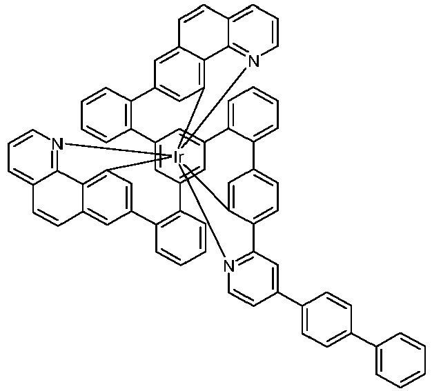

257 258 
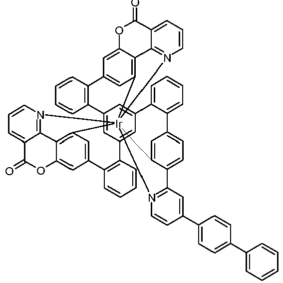
259 260 

261 262 
263 

277 278 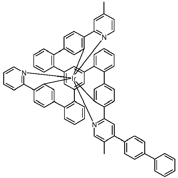

289 290 

291 292 

293 294 

295 296 

297 298 

299 300 

301 302 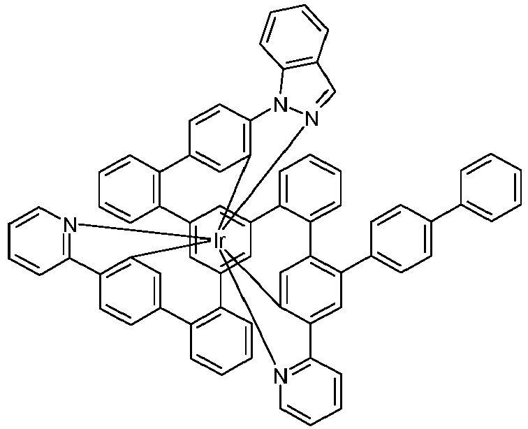

303 304 

305 306 
307 

309 310 

311 312 

313 314 

315 316 
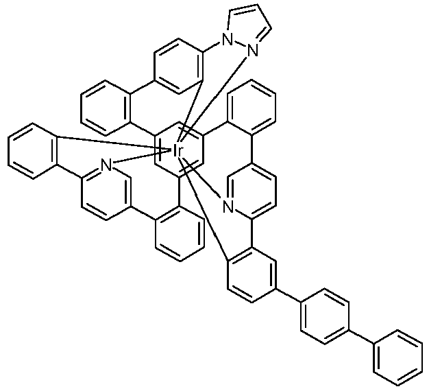
317 318 

319 320 

321 322 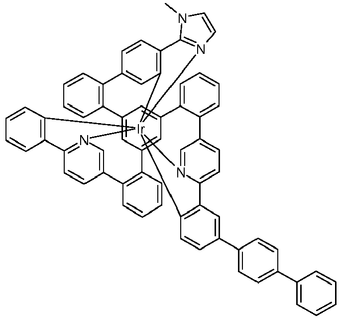

323 324 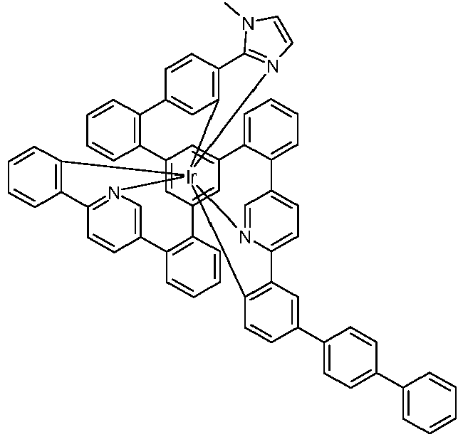

325 326 

327 328 

329 330 

331 332 
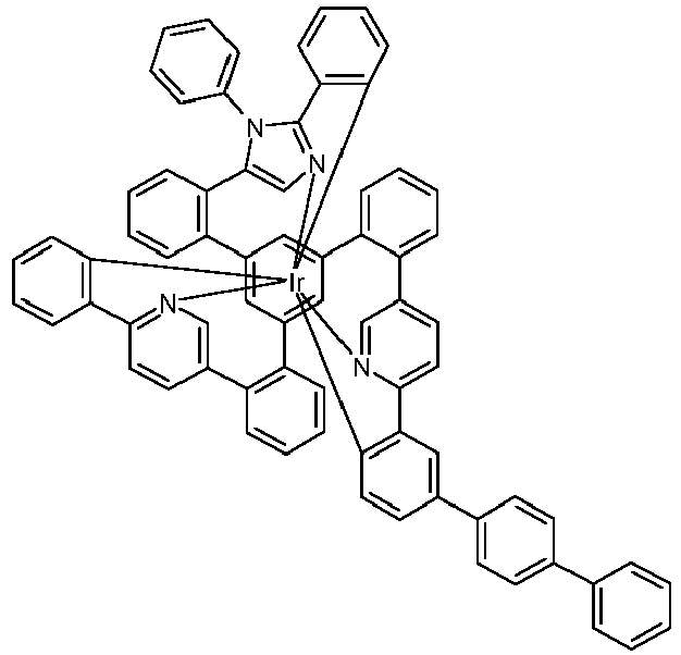
333 334 

335 336 

337 338 

339 340 
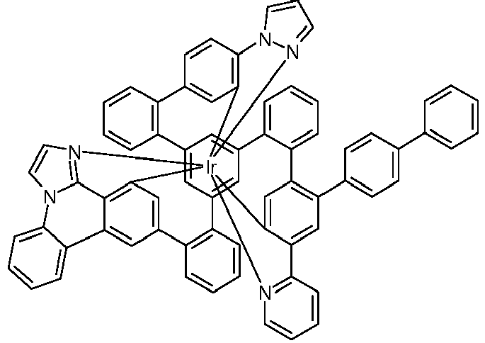
341 342 

343 344 - Bei den erfindungsgemäßen Metallkomplexen handelt es sich um chirale Strukturen. Wenn zusätzlich auch der tripodale Ligand des Komplexes chiral ist, ist die Bildung von Diastereomeren und mehreren Enantiomerenpaaren möglich. Die erfindungsgemäßen Komplexe umfassen dann sowohl die Mischungen der verschiedenen Diastereomere bzw. die entsprechenden Racemate wie auch die einzelnen isolierten Diastereomere bzw. Enantiomere.
- Werden in der ortho-Metallierung Liganden mit zwei identischen Teilliganden L2 eingesetzt, fällt üblicherweise ein racemisches Gemisch der C1-symmetrischen Komplexe, also des Δ- und des Λ-Enantiomers, an. Diese können durch gängige Methoden (Chromatographie an chiralen Materialien / Säulen oder Racemattrennung durch Kristallisation) getrennt werden, wie in Schema 1 dargestellt, wobei R für eine Gruppe der Formel (3) oder (4) steht.

- Die Racemattrennung via fraktionierter Kristallisation von diastereomeren Salzpaaren kann nach üblichen Methoden erfolgen. Hierzu bietet es sich an, die neutralen Ir(III)-Komplexe zu oxidieren (z. B. mit Peroxiden, H2O2 oder elektrochemisch), die so erzeugten kationischen Ir(IV)-Komplexe mit dem Salz einer enantiomerenreinen, monoanionischen Base (chirale Base) zu versetzen, die so erzeugten diasteromeren Salze durch fraktionierte Kristallisation zu trennen und diese dann mit Hilfe eines Reduktionsmittels (z. B. Zink, Hydrazinhydrat, Ascorbinsäure, etc.) zu den enantiomerenreinen neutralen Komplex zu reduzieren, wie in Schema 2 dargestellt.

- Daneben ist eine enantiomerenreine bzw. enantiomerenanreichernde Synthese durch Komplexierung in einem chiralen Medium (z. B. R- oder S-1,1-Binaphthol) möglich.
- Werden in der Komplexierung Liganden mit drei unterschiedlichen Teilliganden L1 und L2 eingesetzt, fällt üblicherweise ein Diastereomerengemisch der Komplexe an, das durch gängige Methoden (Chromatographie, Kristallisation, etc.) getrennt werden kann.
- Enantiomerenreine C1-symmetrische Komplexe können auch gezielt synthetisiert werden, wie in Schema 3 dargestellt. Dazu wird ein enantiomerenreiner, C1-symmetrischer Ligand dargestellt, komplexiert, das erhaltene Diastereomerengemisch wird getrennt und anschließend wird die chirale Gruppe abgespalten.


- Die erfindungsgemäßen Verbindungen sind prinzipiell durch verschiedene Verfahren darstellbar. Generell wird hierzu ein Iridiumsalz mit dem entsprechenden freien Liganden umgesetzt.
- Daher ist ein weiterer Gegenstand der vorliegenden Erfindung ein Verfahren zur Herstellung der erfindungsgemäßen Verbindungen durch Umsetzung der entsprechenden freien Liganden mit Iridiumalkoholaten der Formel (34), mit Iridiumketoketonaten der Formel (35), mit Iridiumhalogeniden der Formel (36) oder mit Iridiumcarboxylaten der Formel (37),

- Es können ebenfalls Iridiumverbindungen, die sowohl Alkoholat- und/oder Halogenid- und/oder Hydroxy- wie auch Ketoketonatreste tragen, verwendet werden. Diese Verbindungen können auch geladen sein. Entsprechende Iridiumverbindungen, die als Edukte besonders geeignet sind, sind in
WO 2004/085449 offenbart. Besonders geeignet sind [IrCl2(acac)2]-, beispielsweise Na[IrCl2(acac)2], Metallkomplexe mit Acetylacetonat-Derivaten als Ligand, beispielsweise Ir(acac)3 oder Tris(2,2,6,6-Tetramethylheptan-3,5-dionato)iridium, und IrCl3·xH2O, wobei x üblicherweise für eine Zahl zwischen 2 und 4 steht. - Die Synthese der Komplexe wird bevorzugt durchgeführt wie in
WO 2002/060910 und inWO 2004/085449 beschrieben. Dabei kann die Synthese beispielsweise auch thermisch, photochemisch und/oder durch Mikrowellenstrahlung aktiviert werden. Weiterhin kann die Synthese auch im Autoklaven bei erhöhtem Druck und/oder erhöhter Temperatur durchgeführt werden. - Die Reaktionen können ohne Zusatz von Lösemitteln oder Schmelzhilfen in einer Schmelze der entsprechenden zu o-metallierenden Liganden durchgeführt werden. Gegebenenfalls können auch Lösemittel oder Schmelzhilfen zugesetzt werden. Geeignete Lösemittel sind protische oder aprotische Lösemittel, wie aliphatische und / oder aromatische Alkohle (Methanol, Ethanol, iso-Propanol, t-Butanol, etc.), Oligo- und Polyalkohole (Ethylenglykol, 1,2-Propandiol, Glycerin, etc.), Alkoholether (Ethoxyethanol, Diethylenglykol, Triethylenglycol, Polyethylenglykol, etc.), Ether (Di- und Triethylenglykoldimethylether, Diphenylether, etc.), aromatische, heteroaromatische und oder aliphatische Kohlenwasserstoffe (Toluol, Xylol, Mesitylen, Chlorbenzol, Pyridin, Lutidin, Chinolin, Isochinolin, Tridecan, Hexadecan, etc.), Amide (DMF, DMAC, etc.), Lactame (NMP), Sulfoxide (DMSO) oder Sulfone (Dimethylsulfon, Sulfolan, etc.). Geeignete Schmelzhilfen sind Verbindungen, die bei Rautemperatur fest vorliegen, jedoch beim Erwärmen der Reaktionsmischung schmelzen und die Reaktanden lösen, so dass eine homogene Schmelze entsteht. Besonders geeignet sind Biphenyl, m-Terphenyl, Triphenylen, R- oder S-Binaphthol oder auch das entsprechende Racemat, 1,2-, 1,3-, 1,4-Bisphenoxybenzol, Triphenylphosphinoxid, 18-Krone-6, Phenol, 1-Naphthol, Hydrochinon, etc.. Dabei ist die Verwendung von Hydrochinon besonders bevorzugt.
- Durch diese Verfahren, gegebenenfalls gefolgt von Aufreinigung, wie z. B. Umkristallisation oder Sublimation, lassen sich die erfindungsgemäßen Verbindungen gemäß Formel (1) in hoher Reinheit, bevorzugt mehr als 99 % (bestimmt mittels 1H-NMR und/oder HPLC) erhalten.
- Die erfindungsgemäßen Verbindungen können auch durch geeignete Substitution, beispielsweise durch längere Alkylgruppen (ca. 4 bis 20 C-Atome), insbesondere verzweigte Alkylgruppen, löslich gemacht werden. Insbesondere auch die Verwendung von ankondensierten aliphatischen Gruppen, wie sie beispielsweise durch die oben offenbarten Formeln (27) bis (33) dargestellt werden, führt zu einer deutlichen Verbesserung der Löslichkeit der Metallkomplexe. Solche Verbindungen sind dann in gängigen organischen Lösemitteln, wie beispielsweise Toluol oder Xylol bei Raumtemperatur in ausreichender Konzentration löslich, um die Komplexe aus Lösung verarbeiten zu können. Diese löslichen Verbindungen eignen sich besonders gut für die Verarbeitung aus Lösung, beispielsweise durch Druckverfahren.
- Für die Verarbeitung der erfindungsgemäßen Iridiumkomplexe aus flüssiger Phase, beispielsweise durch Spin-Coating oder durch Druckverfahren, sind Formulierungen der erfindungsgemäßen Iridiumkomplexe erforderlich. Diese Formulierungen können beispielsweise Lösungen, Dispersionen oder Emulsionen sein. Es kann bevorzugt sein, hierfür Mischungen aus zwei oder mehr Lösemitteln zu verwenden. Geeignete und bevorzugte Lösemittel sind beispielsweise Toluol, Anisol, o-, m- oder p-Xylol, Methylbenzoat, Mesitylen, Tetralin, Veratrol, THF, Methyl-THF, THP, Chlorbenzol, Dioxan, Phenoxytoluol, insbesondere 3-Phenoxytoluol, (-)-Fenchon, 1,2,3,5-Tetramethylbenzol, 1,2,4,5-Tetramethylbenzol, 1-Methylnaphthalin, 2-Methylbenzothiazol, 2-Phenoxyethanol, 2-Pyrrolidinon, 3-Methylanisol, 4-Methylanisol, 3,4-Dimethylanisol, 3,5-Dimethylanisol, Acetophenon, α-Terpineol, Benzothiazol, Butylbenzoat, Cumol, Cyclohexanol, Cyclohexanon, Cyclohexylbenzol, Decalin, Dodecylbenzol, Ethylbenzoat, Indan, NMP, p-Cymol, Phenetol, 1,4-Diisopropylbenzol, Dibenzylether, Diethylenglycolbutylmethylether, Triethylenglycolbutylmethylether, Diethylenglycoldibutylether, Triethylenglycoldimethylether, Diethylenglycolmonobutylether, Tripropyleneglycoldimethylether, Tetraethylenglycoldimethylether, 2-Isopropylnaphthalin, Pentylbenzol, Hexylbenzol, Heptylbenzol, Octylbenzol, 1,1-Bis(3,4-dimethylphenyl)ethan, Hexamethylindan, 2-Methylbiphenyl, 3-Methylbiphenyl, 1-Methylnaphthalin, 1-Ethylnaphthalin, Ethyloctanoat, Sebacinsäure-diethylester, Octyloctanoat, Heptylbenzol, Menthyl-isovalerat, Cyclohexylhexanoat oder Mischungen dieser Lösemittel.
- Ein weiterer Gegenstand der vorliegenden Erfindung ist daher eine Formulierung, enthaltend mindestens eine erfindungsgemäßen Verbindung und mindestens eine weitere Verbindung. Die weitere Verbindung kann beispielsweise ein Lösemittel sein, insbesondere eines der oben genannten Lösemittel oder eine Mischung dieser Lösemittel. Die weitere Verbindung kann aber auch eine weitere organische oder anorganische Verbindung sein, die ebenfalls in der elektronischen Vorrichtung eingesetzt wird, beispielsweise ein Matrixmaterial. Diese weitere Verbindung kann auch polymer sein.
- Die erfindungsgemäße Verbindung kann in der elektronischen Vorrichtung als aktive Komponente, bevorzugt als Emitter in der emissiven Schicht oder als Loch- oder Elektronentransportmaterial in einer loch- bzw. elektronentransportierenden Schicht, oder als Sauerstoff-Sensibilisatoren oder als Photoinitiator oder Photokatalysator verwendet werden. Ein weiterer Gegenstand der vorliegenden Erfindung ist somit die Verwendung einer erfindungsgemäßen Verbindung in einer elektronischen Vorrichtung oder als Sauerstoff-Sensibilisator oder als Photoinitiator oder Photokatalysator. Enantiomerenreine erfindungsgemäße Iridiumkomplexe eignen sich als Photokatalysatoren für chirale photoinduzierte Synthesen.
- Nochmals ein weiterer Gegenstand der vorliegenden Erfindung ist eine elektronische Vorrichtung enthaltend mindestens eine erfindungsgemäße Verbindung.
- Unter einer elektronischen Vorrichtung wird eine Vorrichtung verstanden, welche Anode, Kathode und mindestens eine Schicht enthält, wobei diese Schicht mindestens eine organische bzw. metallorganische Verbindung enthält. Die erfindungsgemäße elektronische Vorrichtung enthält also Anode, Kathode und mindestens eine Schicht, welche mindestens einen erfindungsgemäßen Iridiumkomplex enthält. Dabei sind bevorzugte elektronische Vorrichtungen ausgewählt aus der Gruppe bestehend aus organischen Elektrolumineszenzvorrichtungen (OLEDs, PLEDs), organischen integrierten Schaltungen (O-ICs), organischen Feld-Effekt-Transistoren (O-FETs), organischen Dünnfilmtransistoren (O-TFTs), organischen lichtemittierenden Transistoren (O-LETs), organischen Solarzellen (O-SCs), wobei hierunter sowohl rein organische Solarzellen wie auch farbstoffsensibilisierte Solarzellen verstanden werden, organischen optischen Detektoren, organischen Photorezeptoren, organischen Feld-Quench-Devices (O-FQDs), lichtemittierenden elektrochemischen Zellen (LECs), Sauerstoff-Sensoren oder organischen Laserdioden (O-Laser), enthaltend in mindestens einer Schicht mindestens eine erfindungsgemäße Verbindung. Verbindungen, die im Infraroten emittieren, eignen sich für den Einsatz in organischen Infrarot-Elektrolumineszenzvorrichtungen und Infrorot-Sensoren. Besonders bevorzugt sind organische Elektrolumineszenzvorrichtungen. Aktive Komponenten sind generell die organischen oder anorganischen Materialien, welche zwischen Anode und Kathode eingebracht sind, beispielsweise Ladungsinjektions-, Ladungstransport- oder Ladungsblockiermaterialien, insbesondere aber Emissionsmaterialien und Matrixmaterialien. Die erfindungsgemäßen Verbindungen zeigen besonders gute Eigenschaften als Emissionsmaterial in organischen Elektrolumineszenzvorrichtungen. Eine bevorzugte Ausführungsform der Erfindung sind daher organische Elektrolumineszenzvorrichtungen. Weiterhin können die erfindungsgemäßen Verbindungen zur Erzeugung von Singulett-Sauerstoff oder in der Photokatalyse eingesetzt werden.
- Die organische Elektrolumineszenzvorrichtung enthält Kathode, Anode und mindestens eine emittierende Schicht. Außer diesen Schichten kann sie noch weitere Schichten enthalten, beispielsweise jeweils eine oder mehrere Lochinjektionsschichten, Lochtransportschichten, Lochblockierschichten, Elektronentransportschichten, Elektroneninjektionsschichten, Exzitonenblockierschichten, Elektronenblockierschichten, Ladungserzeugungsschichten und/oder organische oder anorganische p/n-Übergänge. Dabei ist es möglich, dass eine oder mehrere Lochtransportschichten p-dotiert sind, beispielsweise mit Metalloxiden, wie MoO3 oder WO3, oder mit (per)fluorierten elektronenarmen Aromaten oder mit elektronenarmen Cyano-substituieren Heteroaromaten (z. B. gemäß
JP 4747558 JP 2006-135145 US 2006/0289882 ,WO 2012/095143 ), oder mit chinoiden Systemen (z. B. gemäßEP1336208 ) oder mit LewisSäuren, oder mit Boranen (z. B. gemäßUS 2003/0006411 , -
WO 2002/051850 ,WO 2015/049030 ) oder mit Carboxylaten der Elemente der 3. , 4. oder 5. Hauptgruppe (WO 2015/018539 ) und/oder dass eine oder mehrere Elektronentransportschichten n-dotiert sind. - Ebenso können zwischen zwei emittierende Schichten Interlayers eingebracht sein, welche beispielsweise eine Exzitonen-blockierende Funktion aufweisen und/oder die Ladungsbalance in der Elektrolumineszenzvorrichtung steuern und/oder Ladungen erzeugen (Charge-Generation-Layer, z. B. in Schichtsystemen mit mehreren emittierenden Schichten, z. B. in weiß emittierenden OLED-Bauteilen) . Es sei aber darauf hingewiesen, dass nicht notwendigerweise jede dieser Schichten vorhanden sein muss.
- Dabei kann die organische Elektrolumineszenzvorrichtung eine emittierende Schicht enthalten, oder sie kann mehrere emittierende Schichten enthalten. Wenn mehrere Emissionsschichten vorhanden sind, weisen diese bevorzugt insgesamt mehrere Emissionsmaxima zwischen 380 nm und 750 nm auf, so dass insgesamt weiße Emission resultiert, d. h. in den emittierenden Schichten werden verschiedene emittierende Verbindungen verwendet, die fluoreszieren oder phosphoreszieren können. Insbesondere bevorzugt sind Dreischichtsysteme, wobei die drei Schichten blaue, grüne und orange oder rote Emission zeigen (für den prinzipiellen Aufbau siehe z. B.
WO 2005/011013 ) bzw. Systeme, welche mehr als drei emittierende Schichten aufweisen. Es kann sich auch um ein Hybrid-System handeln, wobei eine oder mehrere Schichten fluoreszieren und eine oder mehrere andere Schichten phosphoreszieren. Eine bevorzugte Ausführungsform sind Tandem-OLEDs. Weiß emittierende organische Elektrolumineszenzvorrichtungen können für Beleuchtungsanwendungen oder mit Farbfilter auch für Vollfarb-Displays verwendet werden. - In einer bevorzugten Ausführungsform der Erfindung enthält die organische Elektrolumineszenzvorrichtung den erfindungsgemäßen Iridiumkomplex als emittierende Verbindung in einer oder mehreren emittierenden Schichten.
- Wenn der erfindungsgemäße Iridiumkomplex als emittierende Verbindung in einer emittierenden Schicht eingesetzt wird, wird er bevorzugt in Kombination mit einem oder mehreren Matrixmaterialien eingesetzt. Die Mischung aus dem erfindungsgemäßen Iridiumkomplex und dem Matrixmaterial enthält zwischen 0.1 und 99 Vol.-%, vorzugsweise zwischen 1 und 90 Vol.-%, besonders bevorzugt zwischen 3 und 40 Vol.-%, insbesondere zwischen 5 und 15 Vol.-% des erfindungsgemäßen Iridiumkomplexes bezogen auf die Gesamtmischung aus Emitter und Matrixmaterial. Entsprechend enthält die Mischung zwischen 99.9 und 1 Vol.-%, vorzugsweise zwischen 99 und 10 Vol.-%, besonders bevorzugt zwischen 97 und 60 Vol.-%, insbesondere zwischen 95 und 85 Vol.-% des Matrixmaterials bezogen auf die Gesamtmischung aus Emitter und Matrixmaterial.
- Als Matrixmaterial können generell alle Materialien eingesetzt werden, die gemäß dem Stand der Technik hierfür bekannt sind. Bevorzugt ist das Triplett-Niveau des Matrixmaterials höher als das Triplett-Niveau des Emitters.
- Geeignete Matrixmaterialien für die erfindungsgemäßen Verbindungen sind Ketone, Phosphinoxide, Sulfoxide und Sulfone, z. B. gemäß
WO 2004/013080 ,WO 2004/093207 ,WO 2006/005627 oderWO 2010/006680 , Triarylamine, Carbazolderivate, z. B. CBP (N,N-Bis-carbazolylbiphenyl), m-CBP oder die inWO 2005/039246 ,US 2005/0069729 ,JP 2004/288381 EP 1205527 ,WO 2008/086851 oderUS 2009/0134784 offenbarten Carbazolderivate, Biscarbazolderivate, Indolocarbazolderivate, z. B. gemäßWO 2007/063754 oderWO 2008/056746 , Indenocarbazolderivate, z. B. gemäßWO 2010/136109 oderWO 2011/000455 , Azacarbazole, z. B. gemäßEP 1617710 ,EP 1617711 ,EP 1731584 ,JP 2005/347160 WO 2007/137725 , Silane, z. B. gemäßWO 2005/111172 , Azaborole oder Boronester, z. B. gemäßWO 2006/117052 , Diazasilolderivate, z. B. gemäßWO 2010/054729 , Diazaphospholderivate, z. B. gemäßWO 2010/054730 , Triazinderivate, z. B. gemäßWO 2010/015306 ,WO 2007/063754 oderWO 2008/056746 , Zinkkomplexe, z. B. gemäßEP 652273 WO 2009/062578 , Dibenzofuranderivate, z. B. gemäßWO 2009/148015 ,WO 2015/169412 ,WO 2017/148564 oderWO 2017/148565 , oder verbrückte Carbazolderivate, z. B. gemäßUS 2009/0136779 ,WO 2010/050778 ,WO 2011/042107 oderWO 2011/088877 . - Es kann auch bevorzugt sein, mehrere verschiedene Matrixmaterialien als Mischung einzusetzen, insbesondere mindestens ein elektronenleitendes Matrixmaterial und mindestens ein lochleitendes Matrixmaterial. Eine bevorzugte Kombination ist beispielsweise die Verwendung eines aromatischen Ketons, eines Triazin-Derivats oder eines Phosphinoxid-Derivats mit einem Triarylamin-Derivat oder einem Carbazol-Derivat als gemischte Matrix für den erfindungsgemäßen Metallkomplex. Ebenso bevorzugt ist die Verwendung einer Mischung aus einem ladungstransportierenden Matrixmaterial und einem elektrisch inerten Matrixmaterial (so genannter "wide bandgap host"), welches nicht bzw. nicht in wesentlichem Maße am Ladungstransport beteiligt ist, wie z. B. in
WO 2010/108579 oderWO 2016/184540 beschrieben. Ebenso bevorzugt ist die Verwendung von zwei elektronentransportierenden Matrixmaterialien, beispielsweise Triazinderivaten und Lactamderivaten, wie z. B. inWO 2014/094964 beschrieben. - Nachfolgend sind Beispiele für Verbindungen abgebildet, die sich als Matrixmaterialien für die erfindungsgemäßen Verbindungen eignen.
- Beispiele für Triazine und Pyrimidine, welche als elektronentransportierende Matrixmaterialien eingesetzt werden können, sind die folgenden Strukturen:


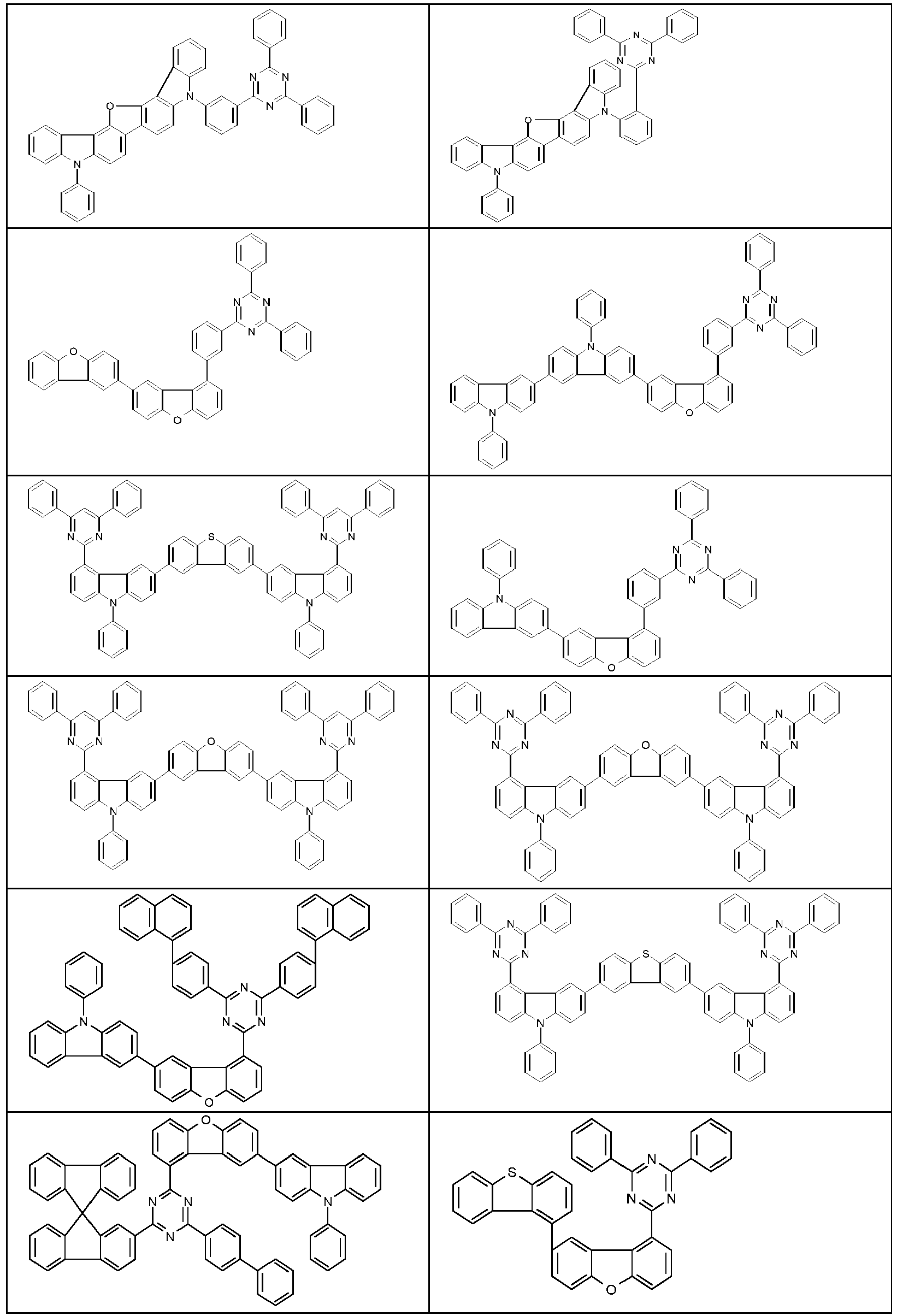


- Beispiele für Lactame, welche als elektronentransportierende Matrixmaterialien eingesetzt werden können, sind die folgenden Strukturen:


- Beispiele für Indolo- und Indenocarbazolderivate im weitesten Sinn, welche je nach Substitutionsmuster als loch- oder elektronentransportierende Matrixmaterialien eingesetzt werden können, sind die folgenden Strukturen:


- Beispiele für Carbazolderivate, welche je nach Substitutionsmuster als loch- oder elektronentransportierende Matrixmaterialien eingesetzt werden können, sind die folgenden Strukturen:


- Beispiele für verbrückte Carbazolderivate, welche als lochtransportierende Matrixmaterialien eingesetzt werden können:


- Beispiele für Biscarbazolderivate, welche als lochtransportierende Matrixmaterialien eingesetzt werden können:


- Beispiele für Amine, welche als lochtransportierende Matrixmaterialien eingesetzt werden können:


- Beispiele für Materialien, welche als Wide Bandgap Matrixmaterialien eingesetzt werden können:


- Weiterhin bevorzugt ist es, eine Mischung aus zwei oder mehr Triplett-Emittern, insbesondere zwei oder drei Triplettemittern, zusammen mit einem oder mehreren Matrixmaterialien einzusetzen. Dabei dient der Triplett-Emitter mit dem kürzerwelligen Emissionsspektrum als Co-Matrix für den Triplett-Emitter mit dem längerwelligen Emissionsspektrum. So können beispielsweise die erfindungsgemäßen Metallkomplexe mit einem kürzerwelligen, z.B. blau, grün oder gelb emittierenden, Metallkomplex als Co-Matrix kombiniert werden. Es können beispislweise auch erfindungsgemäße Metallkomplexe als Co-Matrix für längerwellig emittierende Triplettemitter, beispielsweise für rot emittierende Triplettemitter, eingesetzt werden. Dabei kann es auch bevorzugt sein, wenn sowohl der kürzerwellig wie auch der längerwellig emittierende Metallkomplex eine erfindungsgemäße Verbindung ist. Eine bevorzugte Ausführungsform bei Verwendung einer Mischung aus drei Triplett-Emittern ist, wenn zwei als Co-Host und einer als emittierendes Material eingesetzt werden. Dabei weisen diese Triplett-Emitter bevorzugt die Emissionsfarben Grün, Gelb und Rot oder Blau, Grün und Orange auf.
- Eine bevorzugte Mischung in der emittierenden Schicht enthält ein elektronentransportierendes Hostmaterial, ein so genanntes "wide bandgap" Hostmaterial, das aufgrund seiner elektronischen Eigenschaften nicht oder nicht in wesentlichem Umfang am Ladungstransport in der Schicht beteiligt ist, einen Co-Dotanden, welcher ein Triplettemitter ist, welcher bei einer kürzeren Wellenlänge als die erfindungsgemäße Verbindung emittiert, sowie eine erfindungsgemäße Verbindung.
- Eine weitere bevorzugte Mischung in der emittierenden Schicht enthält ein elektronentransportierendes Hostmaterial, ein so genanntes "wide band gap" Hostmaterial, das aufgrund seiner elektronischen Eigenschaften nicht oder nicht in wesentlichem Umfang am Ladungstransport in der Schicht beteiligt ist, ein lochtransportierendes Hostmaterial, einen Co-Dotanden, welcher ein Triplettemitter ist, welcher bei einer kürzeren Wellenlänge als die erfindungsgemäße Verbindung emittiert, sowie eine erfindungsgemäße Verbindung.
- Die erfindungsgemäßen Verbindungen lassen sich auch in anderen Funktionen in der elektronischen Vorrichtung einsetzen, beispielsweise als Lochtransportmaterial in einer Lochinjektions- oder -transportschicht, als Ladungserzeugungsmaterial, als Elektronenblockiermaterial, als Lochblockiermaterial oder als Elektronentransportmaterial, beispielsweise in einer Elektronentransportschicht. Ebenso lassen sich die erfindungsgemäßen Verbindungen als Matrixmaterial für andere phosphoreszierende Metallkomplexe in einer emittierenden Schicht einsetzen.
- Als Kathode sind Metalle mit geringer Austrittsarbeit, Metalllegierungen oder mehrlagige Strukturen aus verschiedenen Metallen bevorzugt, wie beispielsweise Erdalkalimetalle, Alkalimetalle, Hauptgruppenmetalle oder Lanthanoide (z. B. Ca, Ba, Mg, Al, In, Mg, Yb, Sm, etc.). Weiterhin eignen sich Legierungen aus einem Alkali- oder Erdalkalimetall und Silber, beispielsweise eine Legierung aus Magnesium und Silber. Bei mehrlagigen Strukturen können auch zusätzlich zu den genannten Metallen weitere Metalle verwendet werden, die eine relativ hohe Austrittsarbeit aufweisen, wie z. B. Ag, wobei dann in der Regel Kombinationen der Metalle, wie beispielsweise Mg/Ag, Ca/Ag oder Ba/Ag verwendet werden. Es kann auch bevorzugt sein, zwischen einer metallischen Kathode und dem organischen Halbleiter eine dünne Zwischenschicht eines Materials mit einer hohen Dielektrizitätskonstante einzubringen. Hierfür kommen beispielsweise Alkalimetall- oder Erdalkalimetallfluoride, aber auch die entsprechenden Oxide oder Carbonate in Frage (z. B. LiF, Li2O, BaF2, MgO, NaF, CsF, Cs2CO3, etc.). Ebenso kommen hierfür organische Alkalimetallkomplexe in Frage, z. B. Liq (Lithiumchinolinat). Die Schichtdicke dieser Schicht beträgt bevorzugt zwischen 0.5 und 5 nm.
- Als Anode sind Materialien mit hoher Austrittsarbeit bevorzugt. Bevorzugt weist die Anode eine Austrittsarbeit größer 4.5 eV vs. Vakuum auf. Hierfür sind einerseits Metalle mit hohem Redoxpotential geeignet, wie beispielsweise Ag, Pt oder Au. Es können andererseits auch Metall/Metalloxid-Elektroden (z. B. Al/Ni/NiOx, Al/PtOx) bevorzugt sein. Für einige Anwendungen muss mindestens eine der Elektroden transparent oder teiltransparent sein, um entweder die Bestrahlung des organischen Materials (O-SC) oder die Auskopplung von Licht (OLED/PLED, O-LASER) zu ermöglichen. Bevorzugte Anodenmaterialien sind hier leitfähige gemischte Metalloxide. Besonders bevorzugt sind Indium-Zinn-Oxid (ITO) oder Indium-Zink-Oxid (IZO). Bevorzugt sind weiterhin leitfähige, dotierte organische Materialien, insbesondere leitfähige dotierte Polymere, z. B. PEDOT, PANI oder Derivate dieser Polymere. Bevorzugt ist weiterhin, wenn auf die Anode ein p-dotiertes Lochtransportmaterial als Lochinjektionsschicht aufgebracht wird, wobei sich als p-Dotanden Metalloxide, beispielsweise MoO3 oder WO3, oder (per)fluorierte elektronenarme Aromaten eignen. Weitere geeignete p-Dotanden sind HAT-CN (Hexacyano-hexaazatriphenylen) oder die Verbindung NPD9 von Novaled. Eine solche Schicht vereinfacht die Lochinjektion in Materialien mit einem tiefen HOMO, also einem betragsmäßig großen HOMO.
- In den weiteren Schichten können generell alle Materialien verwendet werden, wie sie gemäß dem Stand der Technik für die Schichten verwendet werden, und der Fachmann kann ohne erfinderisches Zutun jedes dieser Materialien in einer elektronischen Vorrichtung mit den erfindungsgemäßen Materialien kombinieren.
- Geeignete Ladungstransportmaterialien, wie sie in der Lochinjektions- bzw. Lochtransportschicht bzw. Elektronenblockierschicht oder in der Elektronentransportschicht der erfindungsgemäßen organischen Elektrolumineszenzvorrichtung verwendet werden können, sind beispielsweise die in Y. Shirota et al., Chem. Rev. 2007, 107(4), 953-1010 offenbarten Verbindungen oder andere Materialien, wie sie gemäß dem Stand der Technik in diesen Schichten eingesetzt werden. Bevorzugt sind als Lochtransportmaterialien, die in einer Lochtransport-, Lochinjektions- oder Elektronenblockierschicht in der erfindungsgemäßen Elektrolumineszenzvorrichtung verwendet werden können, Indenofluorenamin-Derivate (z. B. gemäß
WO 06/122630 WO 06/100896 EP 1661888 offenbarten Aminderivate, Hexaazatriphenylenderivate (z. B. gemäßWO 01/049806 US 5,061,569 ), die inWO 95/09147 WO 08/006449 WO 07/140847 WO 2012/034627 ,WO2014/056565 ), Fluoren-Amine (z. B. gemäßEP 2875092 ,EP 2875699 undEP 2875004 ), Spiro-Dibenzopyran-Amine (z. B.EP 2780325 ) und Dihydroacridin-Derivate (z. B. gemäßWO 2012/150001 ). - Die Vorrichtung wird entsprechend (je nach Anwendung) strukturiert, kontaktiert und schließlich hermetisch versiegelt, da sich die Lebensdauer derartiger Vorrichtungen bei Anwesenheit von Wasser und/oder Luft drastisch verkürzt.
- Weiterhin bevorzugt ist eine organische Elektrolumineszenzvorrichtung, dadurch gekennzeichnet, dass eine oder mehrere Schichten mit einem Sublimationsverfahren beschichtet werden. Dabei werden die Materialien in Vakuum-Sublimationsanlagen bei einem Anfangsdruck von üblicherweise kleiner 10-5 mbar, bevorzugt kleiner 10-6 mbar aufgedampft. Es ist auch möglich, dass der Anfangsdruck noch geringer oder noch höher ist, beispielsweise kleiner 10-7 mbar.
- Bevorzugt ist ebenfalls eine organische Elektrolumineszenzvorrichtung, dadurch gekennzeichnet, dass eine oder mehrere Schichten mit dem OVPD (Organic Vapour Phase Deposition) Verfahren oder mit Hilfe einer Trägergassublimation beschichtet werden. Dabei werden die Materialien bei einem Druck zwischen 10-5 mbar und 1 bar aufgebracht. Ein Spezialfall dieses Verfahrens ist das OVJP (Organic Vapour Jet Printing) Verfahren, bei dem die Materialien direkt durch eine Düse aufgebracht und so strukturiert werden.
- Weiterhin bevorzugt ist eine organische Elektrolumineszenzvorrichtung, dadurch gekennzeichnet, dass eine oder mehrere Schichten aus Lösung, wie z. B. durch Spincoating, oder mit einem beliebigen Druckverfahren, wie z. B. Siebdruck, Flexodruck, Offsetdruck oder Nozzle-Printing, besonders bevorzugt aber LITI (Light Induced Thermal Imaging, Thermotransferdruck) oder Ink-Jet Druck (Tintenstrahldruck), hergestellt werden. Hierfür sind lösliche Verbindungen nötig, welche beispielsweise durch geeignete Substitution erhalten werden.
- Die organische Elektrolumineszenzvorrichtung kann auch als Hybridsystem hergestellt werden, indem eine oder mehrere Schichten aus Lösung aufgebracht werden und eine oder mehrere andere Schichten aufgedampft werden. So ist es beispielsweise möglich, eine emittierende Schicht enthaltend einen erfindungsgemäßen Metallkomplex und ein Matrixmaterial aus Lösung aufzubringen und darauf eine Lochblockierschicht und/oder eine Elektronentransportschicht im Vakuum aufzudampfen.
- Diese Verfahren sind dem Fachmann generell bekannt und können von ihm ohne Probleme auf organische Elektrolumineszenzvorrichtungen enthaltend Verbindungen gemäß Formel (1) bzw. die oben aufgeführten bevorzugten Ausführungsformen angewandt werden.
- Die erfindungsgemäßen elektronischen Vorrichtungen, insbesondere organische Elektrolumineszenzvorrichtungen, zeichnen sich durch einen oder mehrere der folgenden überraschenden Vorteile gegenüber dem Stand der Technik aus:
- 1. Die erfindungsgemäßen Metallkomplexe weisen bei Verwendung als Emitter in einer organischen Elektrolumineszenzvorrichtung eine sehr hohe EQE (externe Quanteneffizienz) und eine sehr hohe Leistungseffizienz auf und zeigen orientierte Emission. Insbesondere ist die Effizienz deutlich höher im Vergleich zu Metallkomplexen, die ansonsten die gleiche Ligandenstruktur aufweisen, jedoch keinen Substituenten der Formel (3) aufweisen. Ebenso ist die Effizienz deutlich höher im Vergleich zu Metallkomplexen, die ansonsten die gleiche Ligandenstruktur aufweisen, die jedoch an jedem der drei Teilliganden einen Substituenten der Formel (3) aufweisen.
- 2. Die erfindungsgemäßen Metallkomplexe weisen bei Verwendung als Emitter in einer organischen Elektrolumineszenzvorrichtung eine sehr gute Lebensdauer auf. Insbesondere ist die Lebensdauer bei konstanter Leuchtdichte höher im Vergleich zu Metallkomplexen, die ansonsten die gleiche Ligandenstruktur aufweisen, jedoch keinen Substituenten der Formel (3) aufweisen. Ebenso ist die Lebensdauer höher im Vergleich zu Metallkomplexen, die ansonsten die gleiche Ligandenstruktur aufweisen, die jedoch an jedem der drei Teilliganden einen Substituenten der Formel (3) aufweisen.
- Diese oben genannten Vorteile gehen nicht mit einer Verschlechterung der weiteren elektronischen Eigenschaften einher.
- Die Erfindung wird durch die nachfolgenden Beispiele näher erläutert, ohne sie dadurch einschränken zu wollen. Der Fachmann kann aus den Schilderungen ohne erfinderisches Zutun weitere erfindungsgemäße elektronische Vorrichtungen herstellen und somit die Erfindung im gesamten beanspruchten Bereich ausführen.
- Die nachfolgenden Synthesen werden, sofern nicht anders angegeben, unter einer Schutzgasatmosphäre in getrockneten Lösungsmitteln durchgeführt. Die Metallkomplexe werden zusätzlich unter Ausschluss von Licht bzw. unter Gelblicht gehandhabt. Die Lösungsmittel und Reagenzien können z. B. von Sigma-ALDRICH bzw. ABCR bezogen werden. Die jeweiligen Angaben in eckigen Klammern bzw. die zu einzelnen Verbindungen angegebenen Nummern beziehen sich auf die CAS-Nummern der literaturbekannten Verbindungen. Bei Verbinden die mehrere tautomere Formen ausweisen können wird eine tautomere Form stellvertretend gezeigt.
- Für die Bestimmung, ob das Strukturfragment Ir(L2) eine höhere Triplettenergie aufweist als das Strukturfragment Ir(L1), wird eine quantenchemische Rechnung durchgeführt. Dafür wird die Triplettenergie der jeweiligen pseudohomoleptischen Komplexe bestimmt, also eines Komplexes der Formel (1), der jedoch drei Teilliganden L1 aufweist, und eines Komplexes der Formel (1), der jedoch drei Teilliganden L2 aufweist, wobei die Komplexe außer den Teilliganden L1 bzw. L2 die jeweils gleiche Struktur aufweisen.
- Das Triplettniveau (= Triplettenergie = E(T1)) der C3-symmetrischen, trispseudo-homoleptischen Metallkomplexe wird über quantenchemische Rechnungen bestimmt. Die hierin beschriebene Methode ist jedoch unabhängig von dem verwendeten Softwarepaket und liefert immer dieselben Ergebnisse. Beispiele oft benutzter Programme für diesen Zweck sind "Gaussian09" (Gaussian Inc.) und Q-Chem 4.1 (Q-Chem, Inc.). Vorliegend wird zur Berechnung der Energien das Programmpaket "Gaussian09, Revision D.01" (Gaussian Inc.) verwendet.
- Die Geometrie wird mit der Methode Hartree-Fock und dem Basissatz LanL2MB (Gaussian-Eingabezeile"# HF/LanL2MB opt") optimiert (Ladung 0, Multiplizität 1). Im Anschluss erfolgt auf Grundlage der optimierten Geometrie eine Energierechnung (single point) für den elektronischen Grundzustand und das Triplett-Niveau.
- Hierbei wird die TDDFT-Methode (time dependent density functional theory) B3PW91 mit dem Basissatz 6-31G(d) (Gaussian-Eingabezeile"# B3PW91/6-31G(d) td=(50-50,nstates=4)") verwendet (Ladung 0, Multiplizität 1) für alle Atome außer Iridium. Für das Iridiumatom wird der Basissatz "LanL2DZ" verwendet (Gaussian-Eingabezeile "#B3PW91/gen pseudo=lanl2 td=(50-50,nstates=4)").
- Das Triplettniveau eines Materials ist definiert als die relative Anregungsenergie (in eV) des Triplettzustands mit der niedrigsten Energie, der sich aus der quantenchemischen Energierechnung ergibt.
- Wenn die Triplettenergie, die aus der Rechnung erhalten wird, des pseudohomoleptischen Komplexes enthaltend den Teilliganden L2 größer ist als die Triplettenergie des pseudohomoleptischen Komplexes enthaltend den Teilliganden L1, dann weist im Sinne der vorliegenden Erfindung das Strukturfragment Ir(L2) eine höhere Triplettenergie auf als das Strukturfragment Ir(L1).
-

- Ein Gemisch aus 26.9 g (100 mmol) 2-(4-Chlor-3-methoxyphenyl)-4,4,5,5-tetramethyl-1,3,2-dioxaborolan [627525-96-6], 19.0 g (120 mmol) 2-Brompyridin, 21.2 g (200 mmol) Natriumcarbonat, 200 ml Toluol, 50 ml Ethanol und 100 ml Wasser wird unter sehr gutem Rühren mit 1.2 g (1 mmol) Tetrakis-triphenylphosphino-palladium(0) versetzt und dann 24 h unter Rückfluss erhitzt. Nach Erkalten trennt man die org. Phase ab, wäscht diese einmal mit 300 ml Wasser, einmal mit 300 ml ges. Kochsalzlösung und trocknet über Magnesiumsulfat. Man filtriert vom Trockenmittel ab, engt das Filtrat um Vakuum vollständig ein und unterzieht den Rückstand einer Kugelrohrdestillation (p ∼ 10-2 mbar, T ∼ 200 °C). Ausbeute: 19.8 g (90 mmol), 90 %; Reinheit: ca. 95 %ig n. 1H-NMR.
- Ein Gemisch aus 23.7 g (100 mmol) 2,5-Dibrompyridin [624-28-2], 23.4 g (100 mmol) 2-(3-Methoxyphenyl)-4,4,5,5-tetramethyl-1,3,2-dioxaborolan [325142-84-5], 27.6 g (200 mmol) Kaliumcarbonat, 50 g Glaskugeln (3 mm Durchmesser), 526 mg (2 mmol) Triphenylphosphin, 225 mg (1 mmol) Palladium(II)acetat, 200 ml Acetonitril und 100 ml Methanol wird unter gutem Rühren 16 h unter Rückfluss erhitzt. Nach Erkalten entfernt man das Lösungsmittel weitgehend im Vakuum, nimmt den Rückstand in 500 ml Ethylacetat auf, wäscht dreimal mit je 200 ml Wasser und einmal mit 300 ml ges. Kochsalzlösung und trocknet über Magnesiumsulfat. Man filtriert vom Trockenmittel ab, engt das Filtrat zur Trockene ein und kristallisiert den Feststoff aus Acetonitril um. Ausbeute: 18.3 g (68 mmol), 68 %; Reinheit: ca. 95 %ig n. 1H-NMR.
- Analog können folgende Verbindungen dargestellt werden.
Bsp. Edukte Variante Produkt Ausbeute S2 

83% 627525-96-6 A S3 

85% 627525-96-6 A S4 

88% 627525-96-6 A S5 

74% 89488-29-9 
195062-61-4 A S6 

70% 1227574-33-5 195062-61-4 A S7 

65% 624-28-2 
325142-84-5 B S8 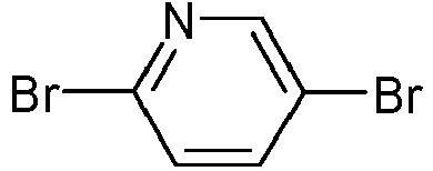

69% 624-28-2 
1417036-28-2 B S9 

67% 1381937-40-1 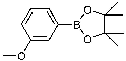
325142-84-5 B S10 

65% 1211520-71-6 
24388-23-6 B S11 

70% 1211520-71-6 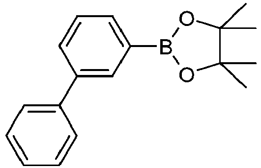
912844-88-3 B S12 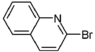

73% 2005-43-8 627525-96-6 A S13 

77% 857206-12-3S 627525-96-6 A S14 
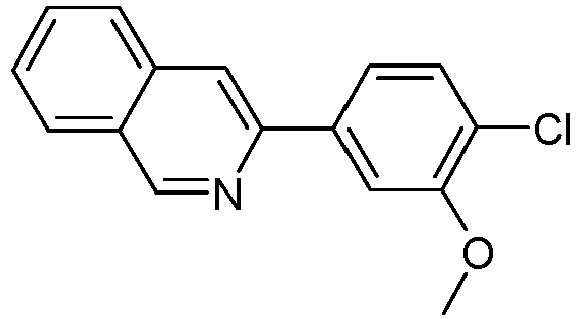
77% 34784-02-6 627525-96-6 A S15 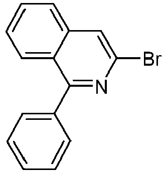

77% 2073111-76-7 627525-96-6 A S16 

73% 1195563-58-6 627525-96-6 A -

- Ein Gemisch aus 22.0 g (100 mmol) S1, 26.7 g (105 mmol) Bis(pinacolato)diboran, 29.4 g (300 mmol) Kaliumacetat (wasserfrei), 50 g Glaskugeln (3 mm Durchmesser) und 300 ml THF wird unter gutem Rühren mit 821 mg (2 mmol) SPhos und dann mit 225 mg (1 mmol) Palladium(II)-acetat versetzt und 16 h unter Rückfluss erhitzt. Nach Erkalten saugt man von den Salzen und Glaskugeln über ein mit THF vorgeschlämmtes Celite-Bett ab, wäscht dieses mit etwas THF nach und engt das Filtrat zur Trockene ein. Man nimmt den Rückstand in 100 ml MeOH auf, rührt warm aus, saugt vom auskristallisierten Produkt ab, wäscht zweimal mit je 30 ml Methanol nach und trocknet im Vakuum. Ausbeute: 27.4 g (88 mmol), 88 %; Reinheit: ca. 95 %ig n. 1H-NMR.
- Durchführung analog zu Variante A, jedoch wird das SPhos durch Tricyclohexylphosphin ersetzt.
- Analog können folgende Verbindungen dargestellt werden.
Bsp. Edukt Variante Produkt Ausbeute S51 S2 
90% A S52 S3 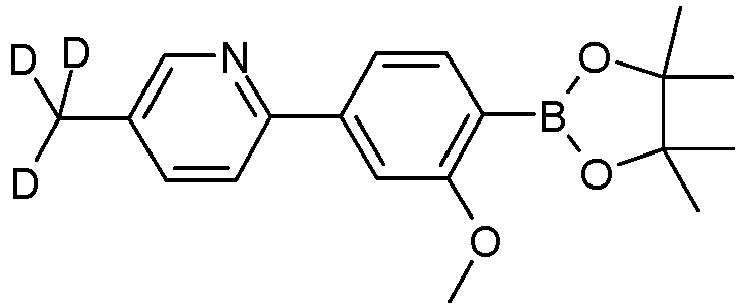
89% A S53 S4 
87% A S54 S5 
90% A S55 S6 
87% A S56 S7 
84% A S57 S8 
88% A S58 S9 
85% B S59 S10 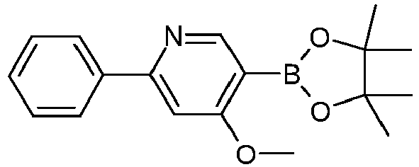
87% A S60 S11 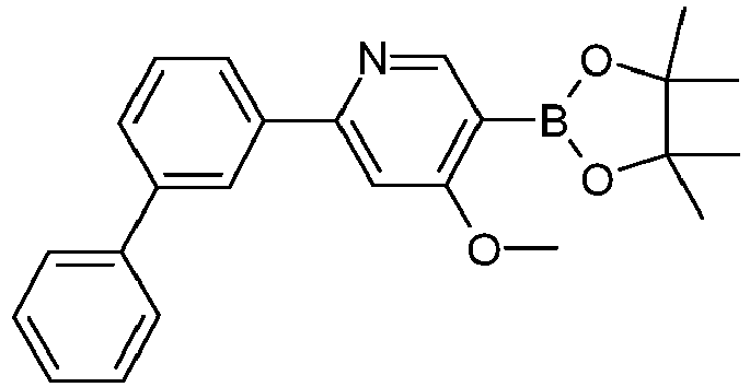
90% A S61 S12 
94% A S62 S13 
91% A S63 S14 
90% A S64 S15 
90% A S65 S16 
90% A S66 

55% 1434057-17-6 A -

- Ein Gemisch aus 31.1 g (100 mmol) S50, 28.3 g (100 mmol) 1-Brom-2-iodbenzol, 31.8 g (300 mmol) Natriumcarbonat, 200 ml Toluol, 70 ml Ethanol und 200 ml Wasser wird unter sehr gutem Rühren mit 788 mg (3 mmol) Triphenylphosphin und dann mit 225 mg (1 mmol) Palladium(II)-acetat versetzt und 48 h unter Rückfluss erhitzt. Nach Erkalten trennt man die org. Phase ab, wäscht diese einmal mit 300 ml Wasser und einmal mit 300 ml ges. Kochsalzlösung und trocknet über Magnesiumsulfat. Man filtriert vom Trockenmittel ab und engt das Filtrat um Vakuum vollständig ein. Der Rückstand wird Flash-chromatographiert (Säulenautomat Torrent der Fa. A. Semrau). Ausbeute: 32.3 g (95 mmol), 95 %; Reinheit: ca. 97 %ig n. 1H-NMR.
- Analog können folgende Verbindungen dargestellt werden.
Bsp. Edukt Produkt Ausbeute S101 S51 
90% S102 S52 
87% S103 S53 
91% S104 S54 
86% S105 S55 
93% S106 S56 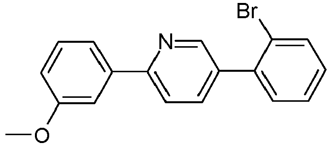
86% S107 S57 
86% S108 S58 
89% S109 S59 
87% S110 S60 
90% S111 S61 
88% S112 S62 
85% S113 S63 
8ß% S114 S64 
80% S115 S65 
76% S116 

80% S117 

89% S118 
86% S119 

85% S120 

77% S121 

80% S122 S66 
67% S123 

85% -

- Ein Gemisch aus 66.3 g (100 mmol) 2,2'-[5"-(4,4,5,5-tetramethyl-1,3,2-dioxaborolan-2-yl)[1,1':2', 1":3", 1'":2"', 1""-quinquephenyl]-4,4""-diyl]bis-pyridine [1989597-72-9], 34.0 g (100 mmol) S100, 63.7 g (300 mmol) Trikaliumphosphat, 300 ml Toluol, 150 ml Dioxan und 300 ml Wasser wird unter gutem Rühren mit 1.64 g (4 mmol) SPhos und dann mit 449 mg (2 mmol) Palladium(II)acetat versetzt und anschließend 24 h unter Rückfluss erhitzt. Nach Erkalten trennt man die org. Phase ab, wäscht diese zweimal mit je 300 ml Wasser und einmal mit 300 ml ges. Kochsalzlösung und trocknet über Magnesiumsulfat. Man filtriert vom Trockenmittel ab, engt das Filtrat im Vakuum zur Trockene ein und kristallisiert das glasartige Rohprodukt in der Siedehitze aus Acetonitril (∼100 ml) unter Zusatz von Ethylacetat (∼20 ml) und dann ein zweites mal aus Butylacetat um. Ausbeute: 68.5 g (86 mmol), 86 %; Reinheit: ca. 95 %ig n. 1H-NMR.
- Analog können folgende Verbindungen dargestellt werden.
Bsp. Edukte Produkt Ausbeute S151 1989597-72-9 
83% S101 S152 1989597 -72-9 
80% S102 S153 1989597-72-9 
85% S103 S154 

87% Darstellung analog zu 1989597-72-9 gemäß WO 2016/124304 durch Einsatz von 2-Brom-5-methyl pyridinS101 S155 

85% Darstellung analog zu 1989597-72-9 gemäß WO 2016/124304 durch Einsatz von 2-Brom-4-methyl pyridinS103 S156 

88% S100 S157 1989597-72-9 
81% S104 S158 1989597-72-9 
78% S105 S159 

80% S105 S160 

80% 1989597-70-7 S106 S161 1989597-70-7 
78% S107 S162 1989597-70-7 
86% S108 S163 

77% 1989597-71-8 S106 S164 

81% 1989597-74-1 S106 S165 1989597-70-7 
80% S109 S166 1989597-70-7 
82% S110 S167 1989597-71-8 
86% S109 S168 1989597-72-9 
80% S111 S169 

86% S112 S170 

88% S113 S171 1989597-72-9 
85% S114 S172 1989597-72-9 
83% S115 S173 S350 
77% S100 S174 S350 
80% S104 S175 S351 
83% S100 S176 S351 
85% S105 S177 S352 
79% S105 S178 S353 
83% S104 S179 S354 
74% S104 S180 S355 
86% S101 S181 S355 
86% S104 S182 S355 
80% S110 S183 S356 
67% S104 Extraktion der Wasserphase mit DCM S184 S357 
81% S104 -

- Analog können folgende Verbindungen dargestellt werden.
Bsp. Edukte Produkt Ausbeute S201 S151 
90% S202 S152 
92% S203 S153 
94% S204 S154 
90% S205 S155 
94% S206 S156 
90% S207 S157 
95% S208 S158 
95% S209 S159 
95% S210 S160 
90% S211 S161 
90% S212 S162 
89% S213 S163 
90% S214 S164 
93% S215 S165 
90% S216 S166 
91% S217 S167 
95% S218 S168 
92% S219 S169 
95% S220 S170 
92% S221 S171 
95% S222 S172 
93% S223 S173 
90% S224 S174 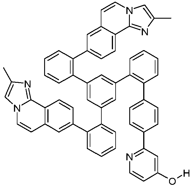
90% S225 S175 
92% S226 S176 
89% S227 S177 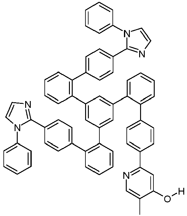
90% S228 S178 
93% S229 S179 
91% S230 S180 
90$ S231 S181 
95% S232 S182 
93% S233 S183 
62% S234 S184 
90% -

- Eine Suspension von 78.2 g (100 mmol) S200 in 1000 ml DCM wird unter Eiskühlung bei 0 °C und gutem Rühren mit 23.7 ml (300 mmol) Pyridin und dann tropfenweise mit 33.6 ml (200 mmol) Trifluormethansulfonsäureanhydrid versetzt. Man rührt 1 h bei 0 °C und dann 4 h bei Raumtemperatur nach. Man gießt die Reaktionslösung auf 3 I Eiswasser, rührt 15 min. nach, trennt die org. Phase ab, wäscht diese einmal mit 300 ml Eiswasser und einmal mit 300 ml ges. Kochsalzlösung, trocknet über Magnesiumsulfat, filtriert vom Trockenmittel ab, engt das Filtrat zur Trockene und kristallisiert den Schaum aus Ethylacetat in der Siedehitze um. Ausbeute: 68.6 g (75 mmol), 75 %; Reinheit: ca. 95 %ig n. 1H-NMR.
- Analog können folgende Verbindungen dargestellt werden.
Bsp. Edukt Produkt Ausbeute S251 S201 
79% S252 S202 
75% S253 S203 
77% S254 S204 
70% S255 S205 
68% S256 S206 
73% S257 S207 
80% S258 S208 
77% S259 S209 
76% S260 S210 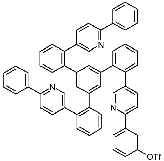
91% S261 S211 
84% S262 S212 
86% S263 S213 
80% S264 S214 
81% S265 S215 
79% S266 S216 
76% S267 S217 
78% S268 S218 
76% S269 S219 
79% S270 S220 
82% S271 S221 
85% S272 S222 
80% S273 S223 
85% S274 S224 
80% S275 S225 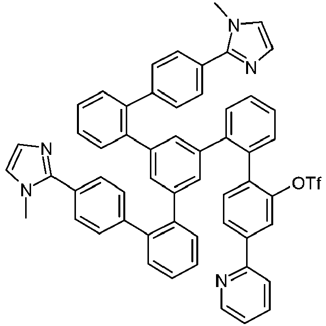
78% S276 S226 
84% S277 S227 
79% S278 S228 
83% S279 S229 
75% S280 S230 
80% S281 S231 
88% S282 S232 
79% S283 S233 
80% S284 S234 
82% -

- Ein gut gerührtes Gemisch aus 67.4 g (200 mmol) S116, 36.5 g (100 mmol) 2,2'-(5-Chlor-1,3-phenylen)bis[4,4,5,5-tetramethyl-1,3,2-dioxaborolan [1417036-49-7], 63.6 g (600 mmol) Natriumcarbonat, 500 ml Toluol, 250 ml Ethanol und 500 ml Wasser wird mit 1.57 g (6 mmol) Triphenylphosphin und dann mit 449 mg (2 mmol) Palladiumacetat versetzt und 24 h unter Rückfluss erhitzt. Nach Erkalten trennt man die org. Phase ab, wäscht diese zweimal mit je 300 ml Wasser und einmal mit 300 ml ges. Kochsalzlösung und trocknet über Magnesiumsulfat. Man filtriert vom Trockenmittel ab, engt das Filtrat im Vakuum zur Trockene ein und kristallisiert das glasartige Rohprodukt in der Siedehitze aus Acetonitril (ca. 150 ml) unter Zusatz von Ethylacetat (ca. 20 ml) um. Ausbeute: 55.0 g (88 mmol), 88 %; Reinheit: ca. 95 %ig n. 1H-NMR.
- Analog können folgende Verbindungen dargestellt werden:
Bsp. Edukt Produkt Ausbeute S301 S117 
83% S302 S118 
83% S303 S119 
85% S304 S120 
89% S305 S121 
88% S306 S122 
60% S307 S123 
86% -

- Darstellung analog zu Beispiel S50, Variante A. Einsatz von 62.5 g (100 mmol) S300. Ausbeute: 64.5 g (90 mmol) 90%; Reinheit: ca. 95 %ig n. 1H-NMR.
- Analog können folgende Verbindungen dargestellt werden:
Bsp. Edukt Produkt Ausbeute S351 S301 
87% S352 S302 
84% S353 S303 
86% S354 S304 
89% S355 S305 
86% S356 S306 
56% S357 S307 
90% -

- Ein Gemisch aus 91.4 g (100 mmol) S250, 30.6 g (110 mmol) 2-[1,1'-Biphenyl]-4-yl-4,4,5,5-tetramethyl-1,3,2-dioxaborolan [144432-80-4], 53.1 g (250 mmol) Trikaliumphosphat, 800 ml THF und 200 ml Wasser wird unter kräftigem Rühren mit 1.64 g (4 mmol) SPhos und dann mit 449 mg (2 mmol) Palladium(II)acetat versetzt und 16 h unter Rückfluss erhitzt. Nach Erkalten trennt man die wässrige Phase ab, engt die org. Phase weitgehend ein, nimmt den Rückstand in 500 ml Ethylacetat auf, wäscht die org. Phase zweimal mit je 300 ml Wasser, einmal mit 2%iger, wässriger N-Acetylcystein-Lösung und einmal mit 300 ml ges. Kochsalzlösung und trocknet über Magnesiumsulfat. Man filtriert vom Trockenmittel über ein mit Ethylacetat vorgeschlämmtes Kieselgel-Bett ab, wäscht mit Ethylacetat nach, engt das Filtrat zur Trockene ein und kristallisiert den Rückstand aus ca. 200 ml Acetonitril unter Zugabe von ca. 50 ml Ethylacetat in der Siedehitze um. Ausbeute: 70.5 g (77 mmol), 77 %; Reinheit: ca. 97 %ig n. 1H-NMR.
- Analog können folgende Verbindungen dargestellt werden.
Bsp. Edukt Produkt Ausbeute L2 

75% L6 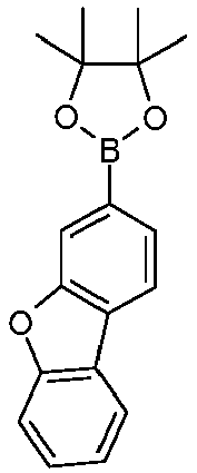

83% L7 

85% L8 

80% L9 
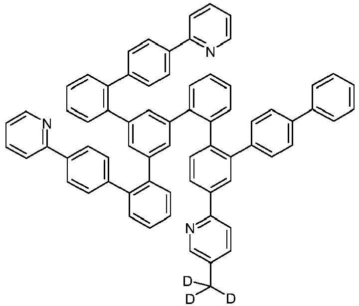
74% L11 

77% L12 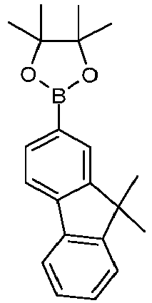

80% L13 

70% L14 

88% L16 

80% L17 

76% L18 

74% L19 

84% L20 

79% L21 
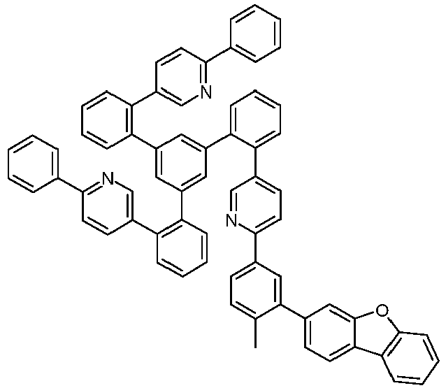
78% L22 

83% L23 

85% L24 

79% L25 

75% L27 

76% L28 
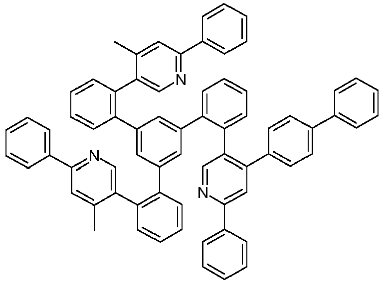
75% L29 

77% L35 

70% L36 
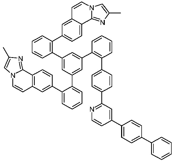
74% L37 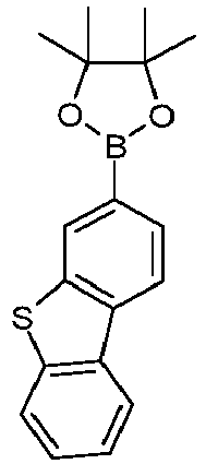

76% L38 

71% L39 

68% L40 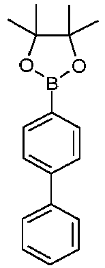

70% L41 

74% L42 

77% L43 

76% L44 

75% L45 

57% L46 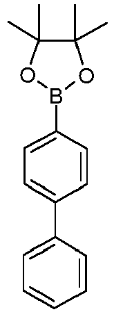
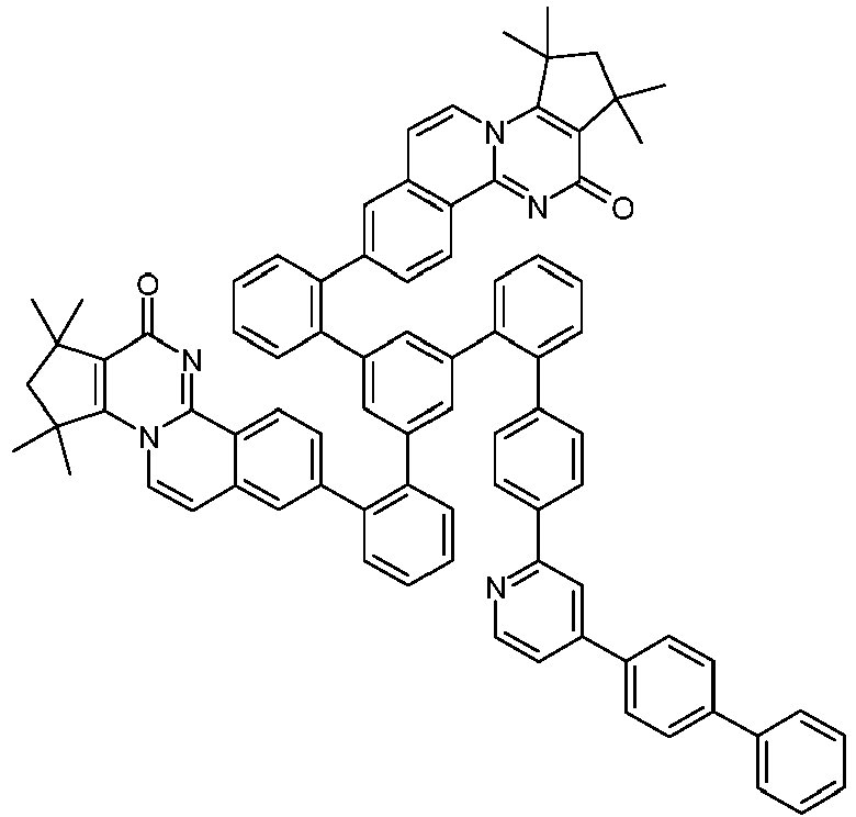
72% -

- Ein Gemisch aus 9.18 g (10 mmol) des Liganden L1, 4.90 g (10 mmol) Tris-acetylacetonato-iridium(III) [15635-87-7] und 120 g Hydrochinon [123-31-9] werden in einem 1000 mL Zweihalsrundkolben mit einem glasummantelten Magnetkern vorgelegt. Der Kolben wird mit einem Wasserabscheider (für Medien geringerer Dichte als Wasser) und einem Luftkühler mit Argonüberlagerung versehen. Der Kolben wird in einer Metallheizschale platziert und die Apparatur über die Argonüberlagerung von oben her 15 min. mit Argon gespült, wobei man das Argon aus dem Seitenhals des Zweihalskolbens ausströmen lässt. Über den Seitenhals des Zweihalskolbens führt man ein glasummanteltes Pt-100 Thermoelement in den Kolben ein und platziert das Ende kurz oberhalb des Magnetrührkerns. Die Apparatur wird mit mehreren lockeren Wicklungen von Haushaltsaluminiumfolie thermisch isoliert, wobei die Isolation bis zur Mitte des Steigrohres des Wasserabscheiders geführt wird. Dann wird die Apparatur schnell mit einem Laborheizrührwerk auf 250-255 °C, gemessen am Pt-100 Thermofühler, der in die aufgeschmolzene, gerührte Reaktionsmischung eintaucht, erhitzt. Während der nächsten 1 h wird das Reaktionsgemisch bei 250-255 °C gehalten, wobei wenig Kondensat abdestilliert und sich im Wasserabscheider sammelt. Nach 1 h lässt man auf 190 °C abkühlen, entfernt die Heizschale und tropft dann 100 ml Ethylenglycol zu. Nach Erkalten auf 100 °C tropft man langsam 400 ml Methanol zu. Die so erhaltene beige Suspension wird über eine Umkehrfritte filtriert. Der beige Feststoff wird dreimal mit 50 ml Methanol gewaschen und dann im Vakuum getrocknet (Rohausbeute: quantitativ). Der so erhaltene Feststoff wird in 200 ml Dichlormethan gelöst und über ca. 1 kg mit Dichlormethan vorgeschlämmtes Kieselgel (Säulendurchmesser ca. 18 cm) unter Luft- und Lichtausschluss filtriert, wobei dunkle Anteile am Start liegen bleiben. Die Kernfraktion wird herausgeschnitten und am Rotationsverdampfer eingeengt, wobei gleichzeitig kontinuierlich MeOH bis zur Kristallisation zugetropft wird. Nach Absaugen, Waschen mit wenig MeOH und Trocknen im Vakuum erfolgt die weitere Reinigung des orangenfarbenen Produkts durch viermalige kontinuierliche Heißextraktion mit Dichlormethan/iso-Propanol 1:1 (vv) und dann viermalige Heißextraktion mit Dichlormethan/Acetonitril (Vorlagemenge jeweils ca. 200 ml, Extraktionshülse: Standard Soxhletthülsen aus Cellulose der Fa. Whatman) unter sorgfältigem Luft- und Lichtausschluss. Über das Verhältnis Dichlormethan (Niedersieder und Gutlöser) : iso-Propanol bzw. Acetonitril (Hochsieder und Schlechtlöser) kann der Verlust in die Mutterlauge eingestellt werden. Typischerweise sollte er 3-6 Gew.-% der eingesetzten Menge betragen. Es können zur Heißextration auch andere Lösungsmittel wie Toluol, Xylol, Essigester, Butylacetat, etc. verwendet werden. Abschließend wird das Produkt im Hochvakuum bei p ∼ 10-6 mbar und T ∼ 400 - 450 °C fraktioniert sublimiert. Ausbeute: 6.65 g (6.0 mmol), 60 %; Reinheit: > 99.9 %ig nach HPLC.
- Durchführung analog Ir(L1) Variante A, jedoch werden statt 120 g Hydrochinon 300 ml Ethylenglycol [111-46-6] verwendet, und es wird 16 h bei 190 °C gerührt. Nach Erkalten auf 70 °C wird mit 300 ml Ethanol verdünnt, der Feststoff wird abgesaugt (P3), dreimal mit je 100 ml Ethanol gewaschen und dann im Vakuum getrocknet. Die weitere Reinigung erfolgt wie unter Variante A beschrieben. Ausbeute: 6.32 g (5.7 mmol), 57 %; Reinheit: > 99.9 %ig nach HPLC.
- Durchführung analog Ir(L1) Variante B, jedoch werden statt 4.90 g (10 mmol) Tris-acetylacetonato-iridium(III) [15635-87-7] 3.53 g (10 mmol) Iridium(III)chlorid x n H2O (n ca. 3) und statt 120 g Hydrochinon 300 ml 2-Ethoxyethanol/Wasser (3:1, vv) verwendet, und es wird 30 h im Rührautoklaven bei 190 °C gerührt. Nach Erkalten wird der Feststoff abgesaugt (P3), dreimal mit je 30 ml Ethanol gewaschen und dann im Vakuum getrocknet. Die weitere Reinigung erfolgt wie unter Variante B beschrieben. Ausbeute: 6.01 g (5.5 mmol), 55 %; Reinheit: > 99.9 %ig nach HPLC.
- Die Metallkomplexe fallen üblicherweise als 1:1 Mischung der A- und Δ-Isomere/Enantiomere an. Die im Folgenden aufgeführten Abbildungen der Komplexen zeigen üblicherweise nur ein Isomer. Werden Liganden mit drei verschiedenen Teilliganden eingesetzt, bzw. werden chirale Liganden als Racemat eingesetzt, fallen die abgeleiteten Metallkomplexe als Diastereomerenmischung an. Diese können durch fraktionierte Kristallisation oder chromatographisch getrennt werden, z. B. mit einem Säulenautomaten (CombiFlash der Fa. A. Semrau). Werden chirale Liganden enantiomerenrein eingesetzt, fallen die abgeleiteten Metallkomplexe als Diastereomerenmischung an, deren Trennung durch fraktionierte Kristallisation oder Chromatographie zu reinen Enantiomeren führt. Die getrennten Diastereomeren bzw. Enantiomeren können wie oben beschrieben z. B. durch Heißextraktion weiter gereinigt werden.
- Analog können folgende Verbindungen dargestellt werden:
Bsp. Ligand Produkt Ausbeute Variante / Extraktionsmittel* Ir(L2) L2 
65% Ir(L6) L6 
60% Ir(L7) L7 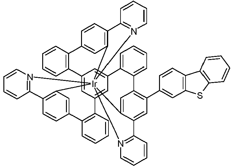
61% Ir(L8) L8 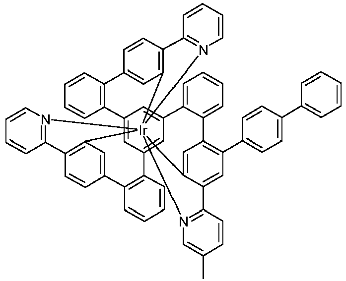
65% Ir(L9) L9 
59% Ir(L11) L11 
62% Ir(L12) L12 
60% Ir(L13) L13 
58% Ir(L14) L14 
64% Ir(L16) L16 
63% Ir(L17) L17 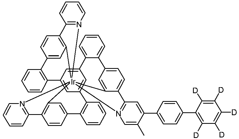
64% Ir(L18) L18 
61% Ir(L19) L19 
70% Ir(L20) L20 
67% Ir(L21) L21 
64% Ir(L22) L22 
71% Ir(L23) L23 
63% Ir(L24) L24 
60% Ir(L25) L25 
65% Ir(L27) L27 
68% Ir(L28) L28 
62% Ir(L29) L29 
64% Ir(L35) L35 
69% Ir(L36) L36 
67% Ir(L37) L37 
63% Ir(L38) L38 
68% Ir(L39) L39 
64% Ir(L40) L40 
65% Ir(L41) L41 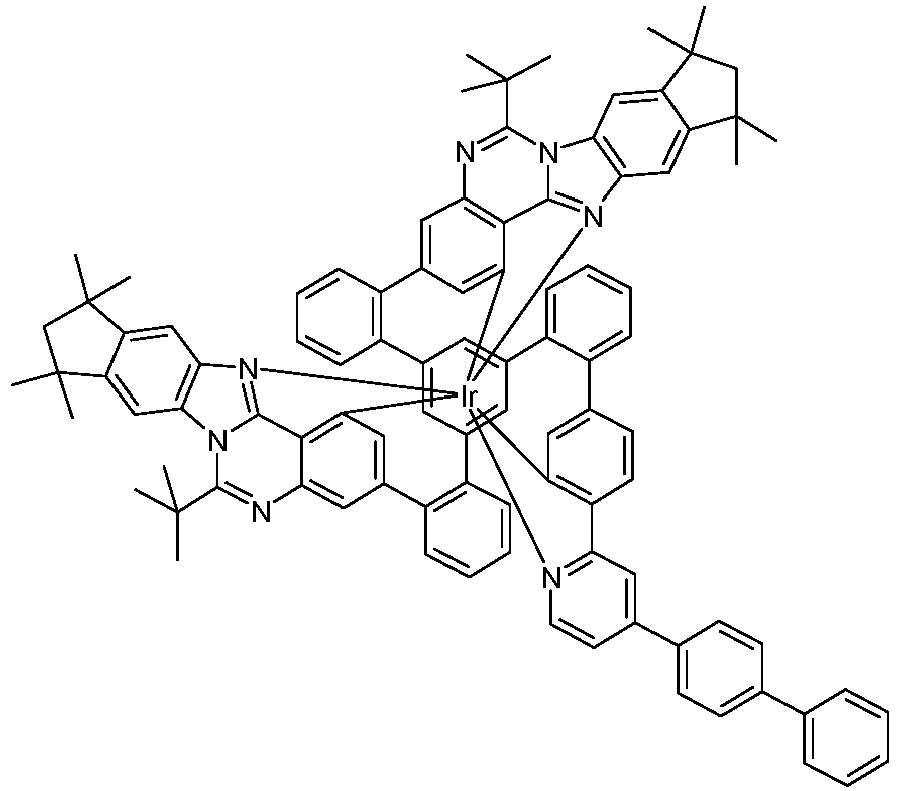
67% Ir(L42) L42 
70% Ir(L43) L43 
68% Ir(L44) L44 
66% Ir(L45) L45 
46% Ir(L46) L46 
65% * sofern abweichend von Standarddurchführung - Eine Suspension von 1 mmol des sauberen Komplexes (Reinheit > 99.9 %) mit x Methylgruppen (x = 1, 2, 3) in einem Gemisch aus 50 ml DMSO-d6 (Deuterierungsgrad > 99.8 %) und 5 ml Methanol-d1 (Deuterierungsgrad > 99.8 %) wird mit 0.2 mmol Natriumhydrid versetzt und dann unter Rühren erhitzt (ca. 100 °C), bis eine klare gelb-orange Lösung entstanden ist. Man rührt weitere 5 min. für Komplexe mit Methylgruppen para zum Pyridin-Stickstoff bzw. weitere 30 min. für Komplexe mit Methylgruppen meta zum Pyridin-Stickstoff nach, kühlt mit Hilfe eines Kaltwasserbades ab, versetzt tropfenweise ab ca. 60 °C mit 5 ml 1N DCl in D2O, rührt 1 h nach, saugt vom Feststoff ab und wäscht diesen dreimal mit je 10 ml H2O/MeOH (1:1, vv) und dann dreimal mit je 10 ml MeOH und trocknet im Vakuum. Der Feststoff wird mit DCM über Kieselgel filtriert. Das Filtrat wird im Vakuum eingeengt, gleichzeitig tropfenweise mit MeOH versetzt und dadurch zur Kristallisation gebracht. Abschließend wird fraktioniert sublimiert, wie unter "C: Darstellung der Metallkomplexe, Variante A" beschrieben. Ausbeute typischerweise 80-90%, Deuterierungsgrad > 95 %.
- Auf die oben beschriebene Weise können folgende deuterierte Komplexe dargestellt werden:
Bsp. Edukt Produkt Ausbeute Ir(L11-D9) Ir(L11) 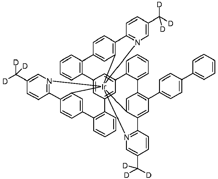
92% Ir(L23-D6) Ir(L23) 
94% Ir(L28-D6) Ir(L28) 
90% - Eine Suspension von 1 mmol des sauberen Komplexes (Reinheit > 99.9 %) in einem Gemisch aus 50 ml DMSO-d6 (Deuterierungsgrad > 99.8 %) und 0.5 ml Methanol-d1 (Deuterierungsgrad > 99.8 %) wird mit 3 mmol Natriumhydrid versetzt und dann unter Rühren auf 140 °C erhitzt. Man rührt 6 h bei 140 °C nach, kühlt die klare orange Lösung mit Hilfe eines Kaltwasserbades ab, versetzt tropfenweise ab ca. 60 °C mit 5 ml 1N DCl in D2O, rührt 1 h nach, saugt vom Feststoff ab, wäscht diesen dreimal mit je 10 ml H2O/MeOH (1:1, vv) und dann dreimal mit je 10 ml MeOH und trocknet im Vakuum. Der Feststoff wird mit DCM über Kieselgel filtriert. Das Filtrat wird im Vakuum eingeengt, gleichzeitig tropfenweise mit MeOH versetzt und dadurch zur Kristallisation gebracht. Abschließend wird fraktioniert sublimiert, wie unter "C: Darstellung der Metallkomplexe, Variante A" beschrieben. Ausbeute typischerweise 80-90 %.
- Auf die oben beschriebene Weise können folgende deuterierte Komplexe dargestellt werden:
Bsp. Edukt Produkt Ausbeute Ir(L1-D9) Ir(L1) 
93% Ir(L6-D9) Ir(L6) 
95% Ir(L19-D3) Ir(L19) 
89% - Eine Lösung bzw. Suspension von 10 mmol eines Komplexes, der in para-Position zum Iridium A x C-H-Gruppen (mit A = 1, 2, 3) trägt, in 500 ml bis 2000 ml Dichlormethan, je nach Löslichkeit der Metallkomplexe, wird unter Licht- und Luftausschluss bei -30 bis +30 °C mit A x 10.5 mmol N-Halogen-succinimid (Halogen: Cl, Br, I) versetzt und 20 h gerührt. In DCM schlecht lösliche Komplexe können auch in anderen Lösemitteln (TCE, THF, DMF, Chlorbenzol, etc.) und bei erhöhter Temperatur umgesetzt werden. Anschließend wird das Lösungsmittel im Vakuum weitgehend entfernt. Der Rückstand wird mit 100 ml Methanol ausgekocht. Der Feststoff wird abgesaugt, dreimal mit 30 ml Methanol gewaschen und im Vakuum getrocknet. Man erhält so die in para-Position zum Iridium bromierten Komplexe. Komplexe mit einem HOMO (CV) von ca. -5.1 bis -5.0 eV und betragsmäßig kleiner neigen zur Oxidation (Ir(III) → Ir(IV)), wobei das Oxidationsmittel Brom, freigesetzt aus NBS, ist. Diese Oxidationsreaktion ist durch eine deutliche Grünfärbung der ansonsten gelben bis roten Lösungen bzw. Suspensionen der Emitter zu erkennen. In solchen Fällen wird ein weiteres Äquivalent NBS zugesetzt. Zur Aufarbeitung setzt man 300-500 ml Methanol und 2 ml Hydrazin Hydrat als Reduktionsmittel zu, wodurch sich die grünen Lösungen bzw. Suspensionen gelb verfärben (Reduktion Ir(IV) → Ir(III). Dann zieht man im Vakuum das Lösemittel weitgehend ab, versetzt mit 300 ml Methanol, saugt den Feststoff ab, wäscht dreimal mit je 100 ml Methanol und trocknet im Vakuum.
- Unterstöchiometrische Bromierungen, z. B. Mono- und Dibromierungen, von Komplexen mit 3 C-H-Gruppen in para-Position zum Iridium verlaufen meist weniger selektiv als die stöchiometrischen Bromierungen. Die Rohprodukte dieser Bromierungen können chromatographisch (CombiFlash Torrent der Fa. A. Semrau) getrennt werden.
-

- Eine bei 0 °C gerührte Suspension von 11.1 g (10 mmol) Ir(L1) in 500 ml DCM wird auf einmal mit 3.7 g (21.0 mmol) N-Bromsuccinimid versetzt und 20 h gerührt. Nach Entfernen von ca. 450 ml des DCMs im Vakuum wird die gelbe Suspension mit 100 ml Methanol versetzt. Der Feststoff wird abgesaugt, dreimal mit ca. 50 ml Methanol gewaschen und im Vakuum getrocknet. Ausbeute: 12.3 g (9.7 mmol), 97 %; Reinheit: > 99.0 %ig nach NMR.
- Analog können folgende Verbindungen dargestellt werden:
Bsp. Edukt Bromierungsprodukt Ausbeute Ir(L6-2Br) Ir(L6) 95% 
I(L11-2Br) Ir(L11) 95% 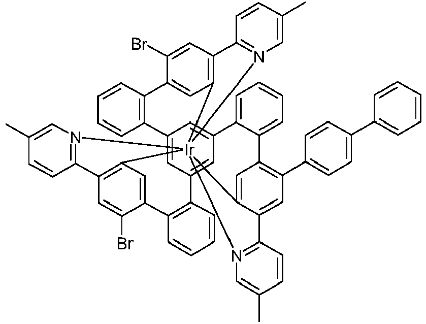
Ir(L14-3Br) Ir(L14) 92% 
Ir(L16-3Br) Ir(I16) 96% 
Ir(L18-3Br) Ir(L18) 94% 
Ir(L19-2Br) Ir(L19) 95% 
Ir(I22-2Br) Ir(L22) 95% 
Ir(L28-3Br) Ir(L28) 93% 
- Ein Gemisch aus 10 mmol des bromierten Komplexes, 20 mmol Kupfer(I)-cyanid pro Brom-Funktion und 300 ml NMP wird 40 h bei 180 °C gerührt. Nach Erkalten entfernt man das Lösemittel im Vakuum, nimmt den Rückstand in 500 ml Dichlormethan auf, filtriert über Celite von den Kupfersalzen ab, engt das Dichlormethan im Vakuum fast bis zur Trockene ein, gibt 100 ml Ethanol zu, saugt vom ausgefallenen Feststoff ab, wäscht diesen zweimal mit je 50 ml Ethanol und trocknet im Vakuum. Das Rohprodukt wird durch Chromatographie und/oder Heißextraktion gereinigt. Das Tempern erfolgt im Hochvakuum (p ca. 10-6 mbar) im Temperaturbereich von ca. 200-300 °C. Die Sublimation erfolgt im Hochvakuum (p ca. 10-6 mbar) im Temperaturbereich von ca. 350-450 °C, wobei die Sublimation bevorzugt in Form einer fraktionierten Sublimation durchgeführt wird.
-

- Einsatz von 12.7 g (10 mmol) Ir(L1-2Br) und 3.6 g (40 mmol) Kupfer(I)-cyanid. Chromatographie an Kieselgel mit Dichlormethan, viermalige Heißextraktion mit Dichlormethan/Acetonitril (2:1, vv), Sublimation. Ausbeute: 6.4 g (5.5 mmol), 55 %; Reinheit: ca. 99.9 %ig nach HPLC.
- Analog können folgende Verbindungen dargestellt werden:
Bsp. Edukt Cyanierungsprodukt Ir(L6-2CN) Ir(L6-2Br) 58% 
Ir(L11-2CN) Ir(L11-2Br) 55% 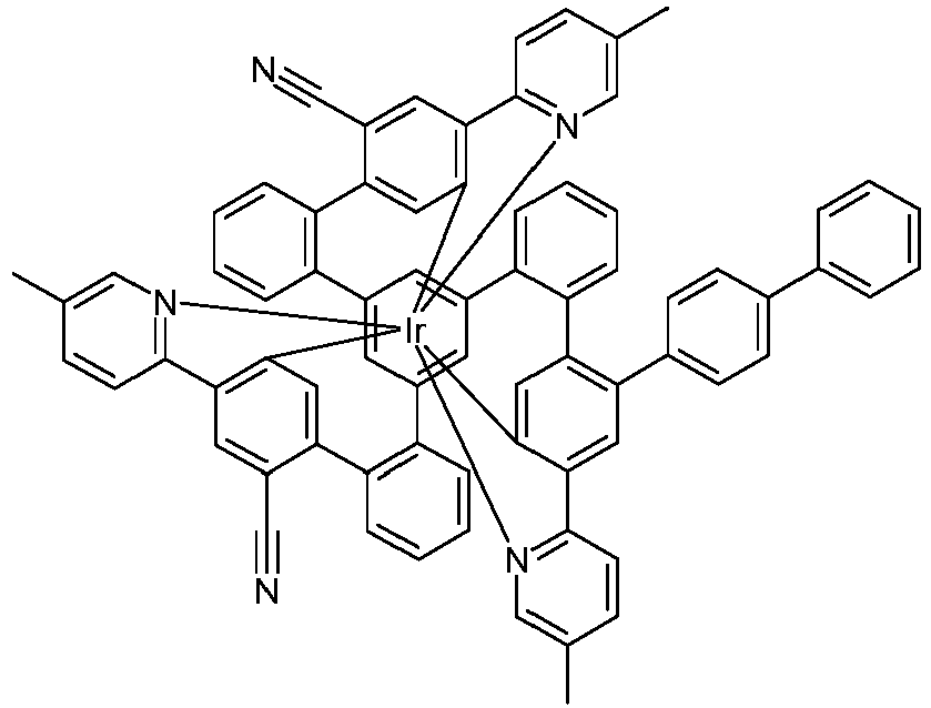
Ir(L14-3CN) Ir(L14-3Br) 51% 
Ir(I16-3CN) Ir(I16-3Br) 56% 
Ir(L18-3CN) Ir(L18-3Br) 53% 
Ir(L19-2CN) Ir(L19-2Br) 60% 
Ir(L22-2CN) Ir(L22-2Br) 58% 
Ir(L28-3CN) Ir(L28-3Br) 59% 
- Die Herstellung von erfindungsgemäßen OLEDs sowie OLEDs nach dem Stand der Technik erfolgt nach einem allgemeinen Verfahren gemäß
WO 2004/058911 , das auf die hier beschriebenen Gegebenheiten (Schichtdickenvariation, verwendete Materialien) angepasst wird. - In den folgenden Beispielen werden die Ergebnisse verschiedener OLEDs vorgestellt. Gereinigte Glasplättchen (Reinigung in Miele Laborspülmaschine, Reiniger Merck Extran), die mit strukturiertem ITO (Indium Zinn Oxid) der Dicke 50 nm beschichtet sind, werden 25 Minuten mit UV-Ozon vorbehandelt (UV-Ozon Generator PR-100, Firma UVP) und innerhalb 30 min. zur verbesserten Prozessierung mit 20 nm PEDOT:PSS beschichtet (Poly(3,4-ethylendioxythiophen)poly(styrolsulfonat), bezogen als CLEVIOS™ P VP Al 4083 von Heraeus Precious Metals GmbH Deutschland, aus wässriger Lösung aufgeschleudert) und anschließend bei 180 °C 10 min. lang ausgeheizt. Diese beschichteten Glasplättchen bilden die Substrate, auf welche die OLEDs aufgebracht werden. Die OLEDs haben prinzipiell folgenden Schichtaufbau: Substrat / Lochinjektionsschicht 1 (HIL1) bestehend aus HTM1 dotiert mit 5 % NDP-9 (kommerziell erhältlich von der Fa. Novaled), 20 nm / Lochtransportschicht 1 (HTL1) bestehend aus HTM1, 220 nm für grüne/gelbe Devices, 110 nm für rote Devices / Lochtransportschicht 2 (HTL2) / Emissionsschicht (EML) / Lochblockierschicht (HBL) / Elektronentransportschicht (ETL) / optionale Elektroneninjektionsschicht (EIL) und abschließend eine Kathode. Die Kathode wird durch eine 100 nm dicke Aluminiumschicht gebildet.
- Zunächst werden vakuum-prozessierte OLEDs beschrieben. Hierfür werden alle Materialien in einer Vakuumkammer thermisch aufgedampft. Dabei besteht die Emissionsschicht immer aus mindestens einem Matrixmaterial (Hostmaterial, Wirtsmaterial) und einem emittierenden Dotierstoff (Dotand, Emitter), der dem Matrixmaterial bzw. den Matrixmaterialien durch Co-Verdampfung in einem bestimmten Volumenanteil beigemischt wird. Eine Angabe wie M1:M2:Ir(L2) (55%:35%:10%) bedeutet hierbei, dass das Material M1 in einem Volumenanteil von 55%, M2 in einem Volumenanteil von 35% und Ir(L1) in einem Volumenanteil von 10% in der Schicht vorliegt. Analog kann auch die Elektronentransportschicht aus einer Mischung zweier Materialien bestehen. Der genaue Aufbau der OLEDs ist Tabelle 1 zu entnehmen. Die zur Herstellung der OLEDs verwendeten Materialien sind in Tabelle 4 gezeigt.
- Die OLEDs werden standardmäßig charakterisiert. Hierfür werden die Elektrolumineszenzspektren, die Stromeffizienz (gemessen in cd/A), die Leistungseffizienz (gemessen in Im/W) und die externe Quanteneffizienz (EQE, gemessen in Prozent) in Abhängigkeit der Leuchtdichte, berechnet aus Strom-Spannungs-Leuchtdichte-Kennlinien (IUL-Kennlinien) unter Annahme einer lambertschen Abstrahlcharakteristik, sowie die Lebensdauer bestimmt. Die Elektrolumineszenzspektren werden bei einer Leuchtdichte von 1000 cd/m2 bestimmt und daraus die CIE 1931 x und y Farbkoordinaten berechnet. Als Lebensdauer LD90 wird die Zeit definiert, nach der die Leuchtdichte bei Betrieb mit einer Starthelligkeit von 10000 cd/m2 auf 90 % der Startleuchtdichte abgesunken ist. Die OLEDs können initital auch bei anderen Startleuchtdichten betrieben werden. Die Werte für die Lebensdauer können dann mit Hilfe dem Fachmann bekannten Umrechnungsformeln auf eine Angabe für andere Startleuchtdichten umgerechnet werden.
- Die erfindungsgemäßen Verbindungen lassen sich unter anderem als phosphoreszierende Emittermaterialien in der Emissionsschicht in OLEDs einsetzen. Als Vergleich gemäß dem Stand der Technik werden die Iridiumkomplexe gemäß Tabelle 4 verwendet. Die Ergebnisse der OLEDs sind in Tabelle 2 zusammengefasst.
Tabelle 1: Aufbau der OLEDs Bsp. HTL2 Dicke EML Dicke HBL Dicke ETL Dicke Ref.D1 HTM2 10 nm M1:M2:Ir-Ref.1 (59%:29%:12%) 30 nm ETM1 10 nm ETM1:ETM2 (50%:50%) 30 nm Ref.D2 HTM2 10 nm M1:M2:Ir-Ref.2 (59%:29%:12%) 30 nm ETM1 10 nm ETM1:ETM2 (50%:50%) 30 nm Ref.D3 HTM2 10 nm M1:M2:Ir-Ref.3 (59%:29%:12%) 30 nm ETM1 10 nm ETM1:ETM2 (50%:50%) 30 nm Ref.D4 HTM2 10 nm M1:M2:Ir-Ref.4 (59%:29%:12%) 30 nm ETM1 10 nm ETM1:ETM2 (50%:50%) 30 nm Ref.D5 HTM2 10 nm M1:M2:Ir-Ref.5 (59%:29%:12%) 30 nm ETM1 10 nm ETM1:ETM2 (50%:50%) 30 nm Ref.D6 HTM2 10 nm M6:Ir-Ref.6 (88%:12%) 40 nm ETM1 10nm ETM1:ETM2 (50%:50%) 30 nm D1A HTM2 10 nm M1:M2:Ir(L1) (59%:29%:12%) 30 nm ETM1 10 nm ETM1:ETM2 (50%:50%) 30 nm D1B HTM2 10 nm M1:M7:Ir(L1) (49%:29%:22%) 30 nm ETM1 10nm ETM1:ETM2 (50%:50%) 30 nm D1C HTM2 10 nm M1:M8:Ir(L1) (68%:25%:7%) 30 nm ETM1 10 nm ETM1:ETM2 (50%:50%) 30 nm D1D HTM2 10 nm M1:M9:Ir(L1) (58%:35%:7%) 30 nm ETM1 10 nm ETM1:ETM2 (50%:50%) 30 nm D1E HTM2 10 nm M1:M9:Ir(L1) (46%:50%:4%) 30 nm ETM1 10 nm ETM1:ETM2 (50%:50%) 30 nm D1-D9 HTM2 10 nm M1:M2:Ir(L1-D9) (59%:29%:12%) 30 nm ETM1 10 nm ETM1:ETM2 (50%:50%) 30 nm D2 HTM2 10 nm M1:M2:Ir(L2) (59%:29%:12%) 30 nm ETM1 10 nm ETM1:ETM2 (50%:50%) 30 nm D6 HTM2 10 nm M1:M2:Ir(L6) (59%:29%:12%) 30 nm ETM1 10 nm ETM1:ETM2 (50%:50%) 30 nm D6-D9 HTM2 10 nm M1:M2:Ir(L6-D9) (59%:29%:12%) 30 nm ETM1 10 nm ETM1:ETM2 (50%:50%) 30 nm D6-2CN HTM2 10 nm M1:M2:Ir(L6-2CN) (29%:59%:12%) 30 nm ETM1 10 nm ETM1:ETM2 (50%:50%) 30 nm D7 HTM2 10 nm M1:M2:Ir(L7) (59%:29%:12%) 30 nm ETM1 10 nm ETM1:ETM2 (50%:50%) 30 nm D8 HTM2 10 nm M1:M2:Ir(L8) (59%:29%:12%) 30 nm ETM1 10 nm ETM1:ETM2 (50%:50%) 30 nm D9 HTM2 10 nm M1:M2:Ir(L9) (59%:29%:12%) 30 nm ETM1 10 nm ETM1:ETM2 (50%:50%) 30 nm D11 HTM2 10 nm M1:M2:Ir(L11) (59%:29%:12%) 30 nm ETM1 10 nm ETM1:ETM2 (50%:50%) 30 nm D11-D9 HTM2 10 nm M1:M2:Ir(L11-D9) (59%:29%:12%) 30 nm ETM1 10 nm ETM1:ETM2 (50%:50%) 30 nm D12 HTM2 10 nm M1:M2:Ir(L12) (59%:29%:12%) 30 nm ETM1 10 nm ETM1:ETM2 (50%:50%) 30 nm D13 HTM2 10 nm M1:M2:Ir(L13) (59%:29%:12%) 30 nm ETM1 10 nm ETM1:ETM2 (50%:50%) 30 nm D14A HTM2 10 nm M1:M2:Ir(L14) (62%:31%:7%) 30 nm ETM1 10 nm ETM1:ETM2 (50%:50%) 30 nm D14B HTM2 10 nm M1:M2:Ir(L14) (59%:29%:12%) 30 nm ETM1 10 nm ETM1:ETM2 (50%:50%) 30 nm D14C HTM2 10 nm M1:M2:Ir(L14) (56%:27%:17%) 30 nm ETM1 10 nm ETM1:ETM2 (50%:50%) 30 nm D14D HTM2 10 nm M1:M2:Ir(L14) (41.5%:41.5%:17%) 30 nm ETM1 10 nm ETM1:ETM2 (50%:50%) 30 nm D14E HTM2 10 nm M1:M7:Ir(L14) (26%:52%:22%) 30 nm ETM1 10 nm ETM1:ETM2 (50%:50%) 30 nm D14-3CN HTM2 10 nm M1:M2:Ir(L14-3CN) (29%:59%:12%) 30 nm ETM1 10 nm ETM1:ETM2 (50%:50%) 30 nm D16 HTM2 10 nm M1:M2:Ir(L16) (59%:29%:12%) 30 nm ETM1 10 nm ETM1:ETM2 (50%:50%) 30 nm D17 HTM2 10 nm M1:M2:Ir(L17) (59%:29%:12%) 30 nm ETM1 10 nm ETM1:ETM2 (50%:50%) 30 nm D18 HTM2 10 nm M1:M2:Ir(L18) (59%:29%:12%) 30 nm ETM1 10 nm ETM1:ETM2 (50%:50%) 30 nm D19 HTM2 10 nm M1:M2:Ir(L19) (41.5%:41.5%:17%) 30 nm ETM1 10 nm ETM1:ETM2 (50%:50%) 30 nm D19-D3 HTM2 10 nm M1:M2:Ir(L19-D3) (41.5%:41.5%:17%) 30 nm ETM1 10 nm ETM1:ETM2 (50%:50%) 30 nm D20 HTM2 10 nm M1:M2:Ir(L20) (41.5%:41.5%:17%) 30 nm ETM1 10 nm ETM1:ETM2 (50%:50%) 30 nm D21 HTM2 10 nm M1:M2:Ir(L21) (41.5%:41.5%:17%) 30 nm ETM1 10 nm ETM1:ETM2 (50%:50%) 30 nm D22 HTM2 10 nm M1:M2:Ir(L22) (41.5%:41.5%:17%) 30 nm ETM1 10 nm ETM1:ETM2 (50%:50%) 30 nm D23 HTM2 10 nm M1:M2:Ir(L23) (41.5%:41.5%:17%) 30 nm ETM1 10 nm ETM1:ETM2 (50%:50%) 30 nm D23-D6 HTM2 10 nm M1:M2:Ir(L23-D6) (41.5%:41.5%:17%) 30 nm ETM1 10 nm ETM1:ETM2 (50%:50%) 30 nm D24 HTM2 10 nm M1:M2:Ir(L24) (41.5%:41.5%:17%) 30 nm ETM1 10 nm ETM1:ETM2 (50%:50%) 30 nm D25 HTM2 10 nm M1:M2:Ir(L25) (41.5%:41.5%:17%) 30 nm ETM1 10 nm ETM1:ETM2 (50%:50%) 30 nm D27 HTM2 10 nm M1:M2:Ir(L27) (41.5%:41.5%:17%) 30 nm ETM1 10 nm ETM1:ETM2 (50%:50%) 30 nm D28 HTM2 10 nm M1:M2:Ir(L28) (41.5%:41.5%:17%) 30 nm ETM1 10 nm ETM1:ETM2 (50%:50%) 30 nm D28-D6 HTM2 10 nm M1:M2:Ir(L28-D6) (41.5%:41.5%:17%) 30 nm ETM1 10 nm ETM1:ETM2 (50%:50%) 30 nm D29 HTM2 10 nm M1:M2:Ir(L29) (41.5%:41.5%:17%) 30 nm ETM1 10 nm ETM1:ETM2 (50%:50%) 30 nm D35 HTM2 10 nm M1:M2:Ir(L35) (59%:29%:12%) 30 nm ETM1 10 nm ETM1:ETM2 (50%:50%) 30 nm D36 HTM2 10 nm M1:M2:Ir(L36) (59%:29%:12%) 30 nm ETM1 10 nm ETM1:ETM2 (50%:50%) 30 nm D37 HTM2 10 nm M1 :M2:lr(L37) (59%:29%:12%) 30 nm ETM1 10 nm ETM1:ETM2 (50%:50%) 30 nm D38 HTM2 10 nm M1:M2:Ir(L38) (59%:29%:12%) 30 nm ETM1 10 nm ETM1:ETM2 (50%:50%) 30 nm D39 HTM2 10 nm M1:M2:Ir(L39) (59%:29%:12%) 30 nm ETM1 10 nm ETM1:ETM2 (50%:50%) 30 nm D40 HTM2 10 nm M1:M2:Ir(L40) (59%:29%:12%) 30 nm ETM1 10 nm ETM1:ETM2 (50%:50%) 30 nm D41 HTM2 10 nm M1:M2:Ir(L41) (59%:29%:12%) 30 nm ETM1 10 nm ETM1:ETM2 (50%:50%) 30 nm D42 HTM2 10 nm M1:M2:Ir(L42) (59%:29%:12%) 30 nm ETM1 10 nm ETM1:ETM2 (50%:50%) 30 nm D43 HTM2 10 nm M1:M2:Ir(L43) (59%:29%:12%) 30 nm ETM1 10 nm ETM1:ETM2 (50%:50%) 30 nm D44 HTM2 10 nm M1:M2:Ir(L44) (59%:29%:12%) 30 nm ETM1 10 nm ETM1:ETM2 (50%:50%) 30 nm D45 HTM2 10 nm M1:M2:Ir(L45) (59%:29%:12%) 30 nm ETM1 10 nm ETM1:ETM2 (50%:50%) 30 nm D46 HTM2 10 nm M1:M2:Ir(L46) (59%:29%:12%) 30 nm ETM1 10 nm ETM1:ETM2 (50%:50%) 30 nm Tabelle 2: Ergebnisse der Vakuum-prozessierten OLEDs Bsp. EQE (%) 1000 cd/m2 Spannung (V) 1000 cd/m2 CIE x/y 1000 cd/m2 LD90 (h) 10000 cd/m2 Ref.D1 17.5 3.2 0.31/0.63 60 Ref.D2 20.2 3.1 0.32/0.64 250 Ref.D3 19.3 3.1 0.40/0.59 150 Ref.D4 24.0 3.1 0.45/0.55 400 Ref.D5 20.9 3.2 0.34/0.62 120 Ref.D6 17.5 3.0 0.41/0.52 120 D1A 22.3 3.2 0.34/0.64 850 D1B 22.6 3.3 0.34/0.64 1200 D1C 20.4 2.8 0.34/0.64 900 D1D 22.6 3.1 0.33/0.64 1000 D1E 22.9 3.0 0.33/0.65 700 D1-D6 22.2 3.2 0.33/0.64 1000 D2 23.5 3.1 0.34/0.63 850 D6 22.8 3.2 0.34/0.64 960 D6-D6 23.8 3.2 0.33/0.64 990 D6-2CN 21.5 3.5 0.27/0.62 280 D7 24.0 3.2 0.34/0.64 940 D8 23.0 3.2 0.34/0.63 920 D9 23.4 3.2 0.34/0.63 950 D11 22.5 3.2 0.35/0.63 850 D11-D9 22.9 3.2 0.34/0.63 900 D12 21.2 3.2 0.34/0.64 820 D13 23.5 3.2 0.34/0.64 920 D14A 29.0 3.0 0.46/0.53 800 D14B 28.8 3.1 0.48/0.52 1100 D14C 27.8 3.2 0.49/0.51 1400 D14D 27.9 3.1 0.49/0.51 1800 D14E 25.3 3.1 0.49/0.50 4400 D14-3CN 26.6 3.6 0.35/0.62 250 D16 29.1 3.1 0.50/0.49 1200 D17 24.8 3.2 0.36/0.62 450 D18 24.9 3.3 0.35/0.63 400 D19 23.7 3.3 0.37/0.61 900 D19-D3 22.8 3.3 0.37/0.61 1000 D20 23.2 3.3 0.35/0.62 550 D21 21.5 3.2 0.36/0.62 4500 D22 22.7 3.3 0.36/0.62 1300 D23 23.7 3.3 0.35/0.62 1100 D23-D6 23.9 3.3 0.35/0.63 1150 D24 22.6 3.2 0.38/0.61 900 D25 24.0 3.1 0.41/0.58 1100 D27 25.4 3.2 0.42/0.57 1200 D28 24.3 3.2 0.40/0.59 1400 D28-D6 24.5 3.1 0.39/0.60 1500 D29 22.7 3.2 0.38/0.61 900 D35 22.4 3.1 0.40/0.60 440 D36 22.3 3.0 0.44/0.55 600 D37 23.1 3.1 0.40/0.60 540 D38 25.8 3.2 0.33/0.62 700 D39 24.0 3.1 0.41/0.58 500 D40 25.1 3.1 0.40/0.59 600 D41 21.5 3.1 0.34/0.63 500 D42 24.5 3.1 0.33/0.63 700 D43 25.5 3.0 0.40/0.58 800 D44 24.9 3.0 0.49/0.50 1100 D45 21.8 3.1 0.27/0.64 500 D46 23.9 3.1 0.48/0.50 550 - Die erfindungsgemäßen Iridiumkomplexe können auch aus Lösung verarbeitet werden und führen dort zu prozesstechnisch wesentlich einfacheren OLEDs, im Vergleich zu den vakuumprozessierten OLEDs, mit dennoch guten Eigenschaften. Die Herstellung solcher Bauteile lehnt sich an die Herstellung polymerer Leuchtdioden (PLEDs) an, die in der Literatur bereits vielfach beschrieben ist (z. B. in der
WO 2004/037887 ). Der Aufbau setzt sich zusammen aus Substrat / ITO / Lochinjektionsschicht (60 nm) / Interlayer (20 nm) / Emissionsschicht (60 nm) / Lochblockierschicht (10 nm) / Elektronentransportschicht (40 nm) / Kathode. Dazu werden Substrate der Firma Technoprint (Sodalimeglas) verwendet, auf welche die ITO-Struktur (Indium-Zinn-Oxid, eine transparente, leitfähige Anode) aufgebracht wird. Die Substrate werden im Reinraum mit DI Wasser und einem Detergens (Deconex 15 PF) gereinigt und dann durch eine UV/Ozon-Plasmabehandlung aktiviert. Danach wird ebenfalls im Reinraum eine 20 nm Lochinjektionsschicht durch Spin-Coating aufgebracht. Die benötigte Spinrate hängt vom Verdünnungsgrad und der spezifischen Spin-Coater-Geometrie ab. Um Restwasser aus der Schicht zu entfernen, werden die Substrate für 30 Minuten bei 200 °C auf einer Heizplatte ausgeheizt. Die verwendete Interlayer dient dem Lochtransport, in diesem Fall wird HL-X von Merck verwendet. Die Interlayer kann alternativ auch durch eine oder mehrere Schichten ersetzt werden, die lediglich die Bedingung erfüllen müssen, durch den nachgelagerten Prozessierungsschritt der EML-Abscheidung aus Lösung nicht wieder abgelöst zu werden. Zur Herstellung der Emissionsschicht werden die erfindungsgemäßen Triplettemitter zusammen mit den Matrixmaterialien in Toluol oder Chlorbenzol gelöst. Der typische Feststoffgehalt solcher Lösungen liegt zwischen 16 und 25 g/L, wenn, wie hier, die für eine Device typische Schichtdicke von 60 nm mittels Spincoating erzielt werden soll. Die lösungsprozessierten Devices vom Typ1 enthalten eine Emissionsschicht aus M4:M5:IrL (18%:60%:22%), die vom Typ2 enthalten eine Emissionsschicht aus M4:M5:IrLa:IrLb (30%:34%:28%:8%), d. h. sie enthalten zwei verschiedene Iridiumkomplexe. Die Emissionsschicht wird in einer Inertgasatmosphäre, im vorliegenden Fall Argon, aufgeschleudert und 10 min bei 160 °C ausgeheizt. Darüber wird die Lochblockierschicht (10 nm ETM1) und die Elektronentransportschicht (40 nm ETM1 (50%) / ETM2 (50%)) aufgedampft (Aufdampfanlagen von Lesker o. a., typischer Aufdampfdruck 5 x 10⁻⁶ mbar). Zuletzt wird eine Kathode aus Aluminium (100 nm) (hochreines Metall von Aldrich) aufgedampft. Um das Device vor Luft und Luftfeuchtigkeit zu schützen, wird die Vorrichtung abschließend verkapselt und dann charakterisiert. Die genannten OLED-Beispiele sind noch nicht optimiert, Tabelle 3 fasst die erhaltenen Daten zusammen. Als Lebensdauer LD50 wird die Zeit definiert, nach der die Leuchtdichte bei Betrieb mit einer Starthelligkeit von 1000 cd/m2 auf 50 % der Startleuchtdichte absinkt.Tabelle 3: Ergebnisse mit aus Lösung prozessierten Materialien Bsp. Emitter Device EQE (%) 1000 cd/m2 Spannung (V) 1000 cd/m2 CIE x/y LD50 (h) 1000 cd/m2 Grüne, Gelbe, Orange und Rote OLEDs Sol-Ref.GreenD1 Ir-Sol-Ref.1 21.8 4.5 0.34/0.62 360000 Sol-GreenD2 Ir(L18) Typ1 23.2 4.2 0.34/0.63 390000 Sol-GreenD3 Ir(L11-2CN) Typ1 M9:M5:IrL (25%:55%:20%) 21.9 4.5 0.27/0.61 60000 Sol-GreenD4 Ir(L14-3CN) M9:M5:IrL (25%:55%:20%) 22.0 4.8 0.23/0.53 40000 Tabelle 4: Strukturformeln der verwendeten Materialien 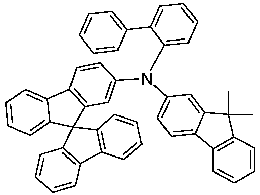

HTM1 [136463-07-5] HTM2 [1450933-44-4] 

M2 M1 [1357150-54-9] [1257248-13-7] 

M5 1246496-85-4 M4 1616231-60-7 

M6 M7 1398395-92-0 1915695-76-5 
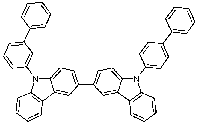
M8 1257248-72-8 M9 1643479-47-3 

ETM2 [25387-93-3] ETM1 = M10 [1233200-52-6] 
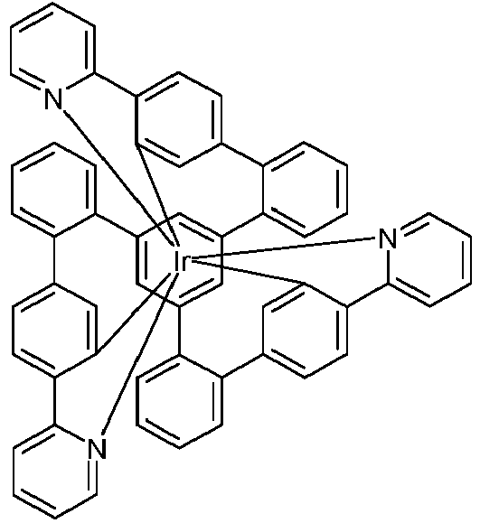
Ir-Ref.1 [94928-86-6] Ir-Ref.2 [1989600-78-3] 

Ir-Ref.4 Ir-Ref.3 Darstellung analog zu [1215281-24-5] nach [1989600-75-0] WO 2010/027583 unterVerwendung von [1810861-59-6] 

Ir-Ref.5 Ir-Ref.6 Darstellung nach WO 1327278-60-3 2004/026886 unter Verwendung von [454454-89-8] und [5122-94-1]
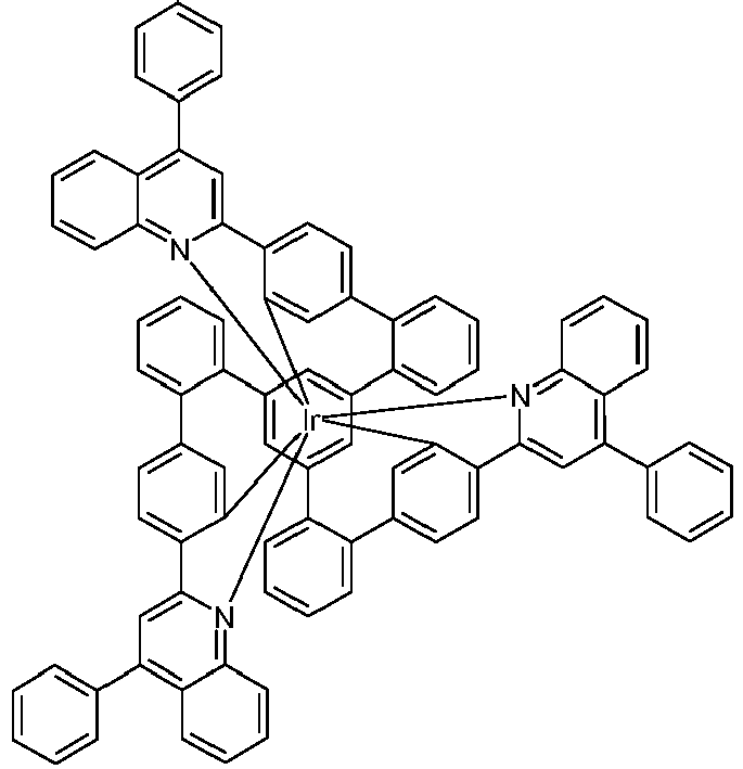
Ir-Sol-Ref.1 Ir-Sol-Ref.2 [1989601-89-9] [1989605-98-2]
Claims (13)
- Verbindung der Formel (1),
 wobei für die verwendeten Symbole gilt:L1 ist ein Teilligand gemäß einer der Formeln (2a) bis (2d), der über die beiden Gruppen D an das Iridium koordiniert und der über die gestrichelte Bindung an V gebunden ist,
 R' ist eine Gruppe der Formel (3),
 wobei die gestrichelte Bindung die Verknüpfung der Gruppe andeutet;R" ist gleich oder verschieden bei jedem Auftreten H, D, F, CN, eine geradkettige Alkylgruppe mit 1 bis 10 C-Atomen, in der auch ein oder mehrere H-Atome durch D oder F ersetzt sein können, oder eine verzweigte oder cyclische Alkylgruppe mit 3 bis 10 C-Atomen, in der auch ein oder mehrere H-Atome durch D oder F ersetzt sein können, oder eine Alkenylgruppe mit 2 bis 10 C-Atomen, in der auch ein oder mehrere H-Atome durch D oder F ersetzt sein können; dabei können auch zwei benachbarte Reste R" bzw. zwei Reste R" an benachbarten Phenylgruppen miteinander ein Ringsystem bilden; oder zwei R" an benachbarten Phenylgruppen stehen zusammen für eine Gruppe ausgewählt aus O oder S, so dass die beiden Phenylringe zusammen mit der verbrückenden Gruppe für ein Dibenzofuran oder Dibenzothiophen stehen, und die weiteren R" sind wie vorstehend definiert;n ist 0, 1, 2, 3, 4 oder 5;L2 ist gleich oder verschieden bei jedem Auftreten ein bidentater, monoanionischer Teilligand, der über ein Kohlenstoffatom und ein Stickstoffatom oder über zwei Kohlenstoffatome oder über zwei Stickstoffatome an das Iridium koordiniert und der mit einem oder mehreren Resten R substituiert sein kann;V ist eine Gruppe der Formel (6b) oder (7b), wobei die gestrichelten Bindungen die Position der Verknüpfung der Teilliganden L1 und L2 darstellen,
 R ist bei jedem Auftreten gleich oder verschieden H, D, F, Cl, Br, I, N(R1)2, OR1, SR1, CN, NO2, COOH, C(=O)N(R1)2, Si(R1)3, B(OR1)2, C(=O)R1, P(=O)(R1)2, S(=O)R1, S(=O)2R1, OSO2R1, eine geradkettige Alkylgruppe mit 1 bis 20 C-Atomen oder eine Alkenyl- oder Alkinylgruppe mit 2 bis 20 C-Atomen oder eine verzweigte oder cyclische Alkylgruppe mit 3 bis 20 C-Atomen, wobei die Alkyl-, Alkenyl- oder Alkinylgruppe jeweils mit einem oder mehreren Resten R1 substituiert sein kann und wobei eine oder mehrere nicht benachbarte CH2-Gruppen durch Si(R1)2, C=O, NR1, O, S oder CONR1 ersetzt sein können, oder eine Aryl- oder Heteroarylgruppe mit 5 bis 10 aromatischen Ringatomen, die jeweils durch einen oder mehrere nicht-aromatische Reste R1 substituiert sein kann; dabei können zwei Reste R auch miteinander ein aliphatisches oder heteroaliphatisches Ringsystem bilden;R1 ist bei jedem Auftreten gleich oder verschieden H, D, F, Cl, Br, I, N(R2)2, OR2, SR2, CN, NO2, Si(R2)3, B(OR2)2, C(=O)R2, P(=O)(R2)2, S(=O)R2, S(=O)2R2, OSO2R2, eine geradkettige Alkylgruppe mit 1 bis 20 C-Atomen oder eine Alkenyl- oder Alkinylgruppe mit 2 bis 20 C-Atomen oder eine verzweigte oder cyclische Alkylgruppe mit 3 bis 20 C-Atomen, wobei die Alkyl-, Alkenyl- oder Alkinylgruppe jeweils mit einem oder mehreren Resten R2 substituiert sein kann und wobei eine oder mehrere nicht benachbarte CH2-Gruppen durch Si(R2)2, C=O, NR2, O, S oder CONR2 ersetzt sein können, oder eine Aryl- oder Heteroarylgruppe mit 5 bis 10 aromatischen Ringatomen, die jeweils durch einen oder mehrere Reste R2 substituiert sein kann; dabei können zwei oder mehrere Reste R1 miteinander aliphatisches oder heteroaliphatisches ein Ringsystem bilden;R2 ist bei jedem Auftreten gleich oder verschieden H, D, F oder ein aliphatischer organischer Rest, insbesondere ein Kohlenwasserstoffrest, mit 1 bis 20 C-Atomen, in dem auch ein oder mehrere H-Atome durch F ersetzt sein können;dabei können die drei bidentaten Teilliganden L1 und L2 außer durch die Brücke V auch noch durch eine weitere Brücke zu einem Kryptat geschlossen sein;dabei ist die folgende Verbindung von der Erfindung ausgenommen:
- Verbindung nach Anspruch 1, dadurch gekennzeichnet, dass L1 eine Struktur gemäß einer der Formeln (2a') bis (2d') aufweist,
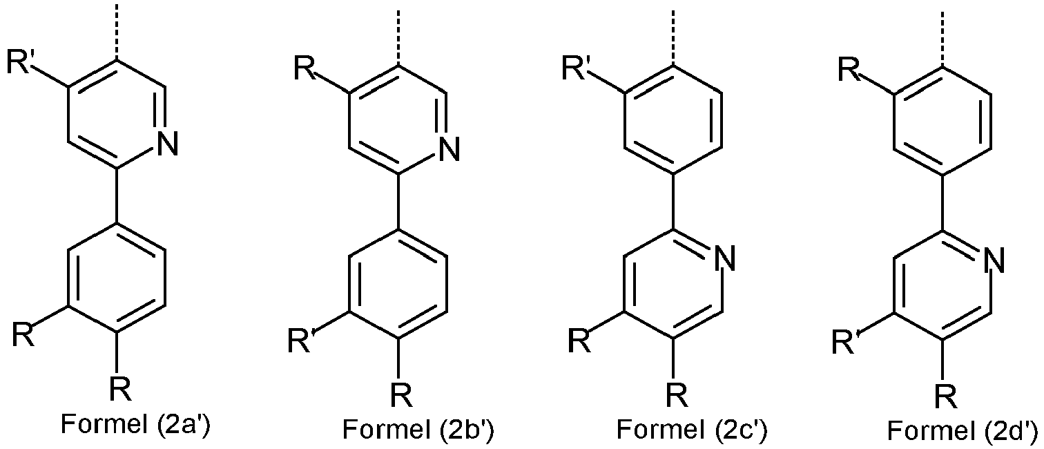
- Verbindung nach Anspruch 1 oder 2, dadurch gekennzeichnet, dass in der Gruppe der Formel (3) beide Substituenten R", welche in den ortho-Positionen zu dem Kohlenstoffatom gebunden sind, mit dem diese Gruppe an den Phenylpyridinliganden gebunden ist, gleich oder verschieden H oder D sind.
- Verbindung nach einem oder mehreren der Ansprüche 1 bis 3, dadurch gekennzeichnet, dass die Struktur der Formel (3) ausgewählt ist aus den Strukturen der Formeln (3a) bis (3n),


- Verbindung nach einem oder mehreren der Ansprüche 1 bis 4, dadurch gekennzeichnet, dass die Substituenten R" gleich oder verschieden bei jedem Auftreten ausgewählt sind aus der Gruppe bestehend aus H, D, CN und einer Alkylgruppe mit 1 bis 4 C-Atomen.
- Verbindung nach einem oder mehreren der Ansprüche 1 bis 5, dadurch gekennzeichnet, dass das Strukturfragment Ir(L2) eine höhere Triplettenergie aufweist als das Strukturfragment Ir(L1).
- Verbindung nach einem oder mehreren der Ansprüche 1 bis 6, dadurch gekennzeichnet, dass L2 gleich oder verschieden bei jedem Auftreten für eine Struktur gemäß den Formeln (L-1), (L-2) oder (L-3) steht,
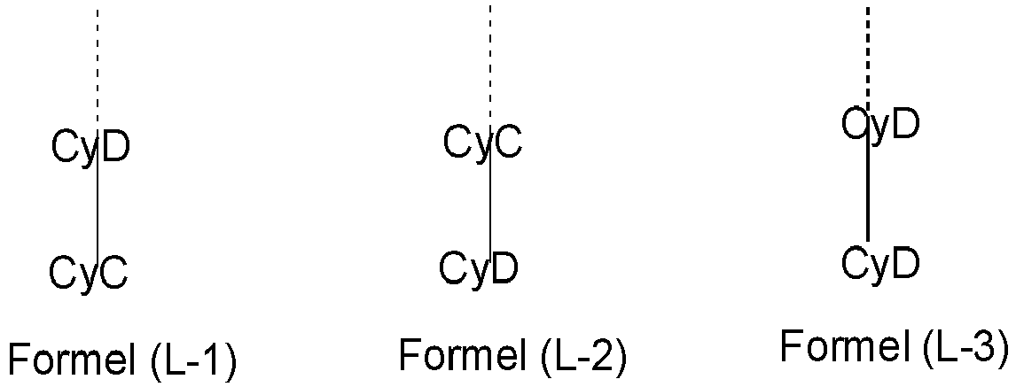 wobei die gestrichelte Bindung die Bindung des Teilliganden an V darstellt und für die weiteren verwendeten Symbole gilt:CyC ist gleich oder verschieden bei jedem Auftreten eine durch R substituierte oder unsubstituierte Aryl- oder Heteroarylgruppe mit 5 bis 14 aromatischen Ringatomen, welche jeweils über ein Kohlenstoffatom an das Metall koordiniert und welche über eine kovalente Bindung mit CyD verbunden ist;CyD ist gleich oder verschieden bei jedem Auftreten eine durch R substituierte oder unsubstituierte Heteroarylgruppe mit 5 bis 14 aromatischen Ringatomen, welche über ein Stickstoffatom oder über ein Carben-Kohlenstoffatom an das Metall koordiniert und welche über eine kovalente Bindung mit CyC verbunden ist;dabei können mehrere der Substituenten R miteinander ein aliphatisches oder heteroaliphatisches Ringsystem bilden, und CyC und CyD können miteinander durch eine Gruppe gemäß einer der Formeln (17) bis (26) verknüpft sein,
 wobei R1 die in Anspruch 1 genannten Bedeutungen aufweist und die gestrichelten Bindungen die Bindungen an CyC bzw. CyD andeuten.
 - Verbindung nach einem oder mehreren der Ansprüche 1 bis 7, dadurch gekennzeichnet, dass die Verbindung zwei Substituenten R oder zwei Substituenten R1 enthält, die an benachbarte Kohlenstoffatome gebunden sind und die miteinander einen Ring gemäß einer der Formeln (27) bis (33) bilden,

 A1, A3 ist gleich oder verschieden bei jedem Auftreten C(R3)2, O, S, NR3 oder C(=O);A2 ist C(R1)2, O, S, NR3 oder C(=O);G ist eine Alkylengruppe mit 1, 2 oder 3 C-Atomen, welche mit einem oder mehreren Resten R2 substituiert sein kann, -CR2=CR2- oder eine ortho-verknüpfte Arylen- oder Heteroarylengruppe mit 5 oder 6 aromatischen Ringatomen, welche durch einen oder mehrere Reste R2 substituiert sein kann;R3 ist gleich oder verschieden bei jedem Auftreten H, F, OR2, eine geradkettige Alkylgruppe mit 1 bis 10 C-Atomen, eine verzweigte oder cyclische Alkylgruppe mit 3 bis 10 C-Atomen, wobei die Alkylgruppe jeweils mit einem oder mehreren Resten R2 substituiert sein kann, wobei eine oder mehrere nicht benachbarte CH2-Gruppen durch R2C=CR2, C≡C, Si(R2)2, C=O, NR2, O, S oder CONR2 ersetzt sein können, oder eine Aryl- oder Heteroarylgruppe mit 5 oder 6 aromatischen Ringatomen, das jeweils durch einen oder mehrere Reste R2 substituiert sein kann; dabei können zwei Reste R3, welche an dasselbe Kohlenstoffatom gebunden sind, miteinander ein aliphatisches Ringsystem bilden und so ein Spirosystem aufspannen; weiterhin kann R3 mit einem benachbarten Rest R oder R1 ein aliphatisches Ringsystem bilden; mit der Maßgabe, dass nicht zwei Heteroatome und nicht zwei Gruppe C=O direkt aneinander gebunden sind.
 - Verfahren zur Herstellung einer Verbindung nach einem oder mehreren der Ansprüche 1 bis 8 durch Umsetzung des entsprechenden Liganden mit Iridiumalkoholaten der Formel (34), Iridiumketoketonaten der Formel (35), Iridiumhalogeniden der Formel (36), Iridiumcarboxylaten der Formel (37) oder Iridiumverbindungen, die sowohl Alkoholat- und/oder Halogenid- und/oder Hydroxy- wie auch Ketoketonatreste tragen,
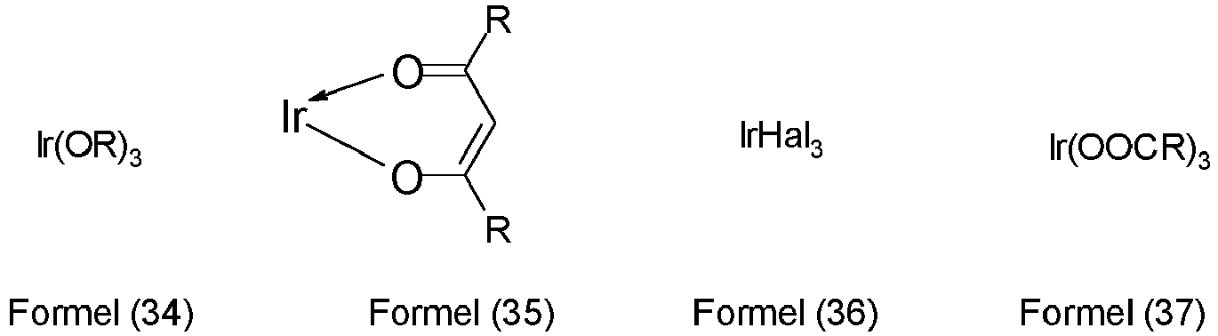
- Formulierung enthaltend mindestens eine Verbindung nach einem oder mehreren der Ansprüche 1 bis 8 und mindestens ein Lösemittel und/oder eine weitere organische oder anorganische Verbindung.
- Verwendung einer Verbindung nach einem oder mehreren der Ansprüche 1 bis 8 in einer elektronischen Vorrichtung oder als Sauerstoff-Sensibilisator oder als Photoinitiator oder Photokatalysator.
- Elektronische Vorrichtung enthaltend mindestens eine Verbindung nach einem oder mehreren der Ansprüche 1 bis 8.
- Elektronische Vorrichtung nach Anspruch 12, dadurch gekennzeichnet, dass es sich um eine organische Elektrolumineszenzvorrichtung handelt und die Verbindung nach einem oder mehreren der Ansprüche 1 bis 8 zusammen mit einem Matrixmaterial in einer oder mehreren emittierenden Schichten vorliegt.
Applications Claiming Priority (3)
| Application Number | Priority Date | Filing Date | Title |
|---|---|---|---|
| EP17163531 | 2017-03-29 | ||
| EP17205103 | 2017-12-04 | ||
| PCT/EP2018/057621 WO2018178001A1 (de) | 2017-03-29 | 2018-03-26 | Metallkomplexe |
Publications (2)
| Publication Number | Publication Date |
|---|---|
| EP3601304A1 EP3601304A1 (de) | 2020-02-05 |
| EP3601304B1 true EP3601304B1 (de) | 2021-10-27 |
Family
ID=61692019
Family Applications (1)
| Application Number | Title | Priority Date | Filing Date |
|---|---|---|---|
| EP18712235.3A Active EP3601304B1 (de) | 2017-03-29 | 2018-03-26 | Metallkomplexe |
Country Status (7)
| Country | Link |
|---|---|
| US (1) | US11569458B2 (de) |
| EP (1) | EP3601304B1 (de) |
| JP (1) | JP7138654B2 (de) |
| KR (1) | KR102603562B1 (de) |
| CN (1) | CN110461859A (de) |
| TW (1) | TWI769231B (de) |
| WO (1) | WO2018178001A1 (de) |
Families Citing this family (87)
| Publication number | Priority date | Publication date | Assignee | Title |
|---|---|---|---|---|
| EP3649213B1 (de) * | 2017-07-05 | 2021-06-23 | Merck Patent GmbH | Zusammensetzung für organische elektronische vorrichtungen |
| TWI776926B (zh) | 2017-07-25 | 2022-09-11 | 德商麥克專利有限公司 | 金屬錯合物 |
| CN111699192B (zh) * | 2018-02-13 | 2024-03-08 | Udc爱尔兰有限公司 | 金属络合物 |
| WO2020011686A1 (de) | 2018-07-09 | 2020-01-16 | Merck Patent Gmbh | Materialien für organische elektrolumineszenzvorrichtungen |
| CN112867709A (zh) | 2018-11-06 | 2021-05-28 | 默克专利有限公司 | 作为用于oled的有机电致发光材料的5,6-二苯基-5,6-二氢-二苯并[c,e][1,2]氮杂磷杂苯和6-苯基-6h-二苯并[c,e][1,2]噻嗪-5,5-二氧化物衍生物及类似化合物 |
| TW202035345A (zh) | 2019-01-17 | 2020-10-01 | 德商麥克專利有限公司 | 用於有機電致發光裝置之材料 |
| TWI850329B (zh) * | 2019-02-11 | 2024-08-01 | 愛爾蘭商Udc愛爾蘭責任有限公司 | 金屬錯合物 |
| EP3938367A1 (de) | 2019-03-12 | 2022-01-19 | Merck Patent GmbH | Materialien für organische elektrolumineszenzvorrichtungen |
| KR20210141593A (ko) | 2019-03-20 | 2021-11-23 | 메르크 파텐트 게엠베하 | 유기 전계 발광 디바이스용 재료 |
| EP3947372A1 (de) | 2019-03-25 | 2022-02-09 | Merck Patent GmbH | Materialien für organische elektrolumineszenzvorrichtungen |
| CN114144421A (zh) | 2019-07-22 | 2022-03-04 | 默克专利有限公司 | 制备邻位金属化金属化合物的方法 |
| EP4021903A1 (de) | 2019-08-26 | 2022-07-06 | Merck Patent GmbH | Materialien für organische elektrolumineszenzvorrichtungen |
| KR20220056223A (ko) | 2019-09-02 | 2022-05-04 | 메르크 파텐트 게엠베하 | 유기 전계발광 디바이스용 재료 |
| CN114401945A (zh) | 2019-09-20 | 2022-04-26 | 默克专利有限公司 | 作为用于电子器件的材料的迫位缩合杂环化合物 |
| US20220416172A1 (en) | 2019-10-22 | 2022-12-29 | Merck Patent Gmbh | Materials for organic electroluminescent devices |
| WO2021078831A1 (de) | 2019-10-25 | 2021-04-29 | Merck Patent Gmbh | In einer organischen elektronischen vorrichtung einsetzbare verbindungen |
| TW202136471A (zh) | 2019-12-17 | 2021-10-01 | 德商麥克專利有限公司 | 有機電致發光裝置用的材料 |
| JP7620631B2 (ja) | 2019-12-18 | 2025-01-23 | メルク パテント ゲゼルシャフト ミット ベシュレンクテル ハフツング | 有機エレクトロルミネッセンス素子のための芳香族化合物 |
| US12552818B2 (en) | 2019-12-19 | 2026-02-17 | Merck Patent Gmbh | Polycyclic compounds for organic electroluminescent devices |
| JP7419865B2 (ja) * | 2020-02-17 | 2024-01-23 | 東ソー株式会社 | 芳香族ハロゲン化合物、その用途、及び製造方法 |
| CN115135741A (zh) | 2020-02-25 | 2022-09-30 | 默克专利有限公司 | 杂环化合物在有机电子器件中的用途 |
| WO2021175706A1 (de) | 2020-03-02 | 2021-09-10 | Merck Patent Gmbh | Verwendung von sulfonverbindungen in einer organischen elektronischen vorrichtung |
| EP4121432A1 (de) | 2020-03-17 | 2023-01-25 | Merck Patent GmbH | Heteroaromatische verbindungen für organische elektrolumineszenzvorrichtungen |
| EP4122028B1 (de) | 2020-03-17 | 2024-10-16 | Merck Patent GmbH | Heterocyclische verbindungen für organische elektrolumineszenzvorrichtungen |
| EP4126868A1 (de) | 2020-03-24 | 2023-02-08 | Merck Patent GmbH | Materialien für elektronische vorrichtungen |
| KR20220158771A (ko) | 2020-03-26 | 2022-12-01 | 메르크 파텐트 게엠베하 | 유기 전계 발광 디바이스용 환형 화합물 |
| KR20220162156A (ko) | 2020-04-02 | 2022-12-07 | 메르크 파텐트 게엠베하 | 유기 전계 발광 디바이스용 재료 |
| EP4132939B1 (de) | 2020-04-06 | 2024-01-31 | Merck Patent GmbH | Polycyclische verbindungen für organische elektrolumineszenzvorrichtungen |
| WO2021239772A1 (de) | 2020-05-29 | 2021-12-02 | Merck Patent Gmbh | Organische elektrolumineszierende vorrichtung |
| KR102914927B1 (ko) | 2020-06-23 | 2026-01-19 | 메르크 파텐트 게엠베하 | 혼합물의 제조 방법 |
| KR20230028315A (ko) | 2020-06-29 | 2023-02-28 | 메르크 파텐트 게엠베하 | 유기 전계 발광 디바이스용 복소환 화합물 |
| KR20230029927A (ko) | 2020-06-29 | 2023-03-03 | 메르크 파텐트 게엠베하 | 유기 전계 발광 디바이스용 헤테로방향족 화합물 |
| US11267788B2 (en) | 2020-07-16 | 2022-03-08 | Dermavant Sciences GmbH | Isoquinoline compounds and their use in treating AhR imbalance |
| EP4192832A1 (de) | 2020-08-06 | 2023-06-14 | Merck Patent GmbH | Materialien für organische elektrolumineszenzvorrichtungen |
| CN116134113B (zh) | 2020-08-13 | 2025-12-26 | Udc爱尔兰有限公司 | 金属络合物 |
| EP4200294A1 (de) | 2020-08-18 | 2023-06-28 | Merck Patent GmbH | Materialien für organische elektrolumineszenzvorrichtungen |
| US20230295104A1 (en) | 2020-08-19 | 2023-09-21 | Merck Patent Gmbh | Materials for organic electroluminescent devices |
| TW202222748A (zh) | 2020-09-30 | 2022-06-16 | 德商麥克專利有限公司 | 用於結構化有機電致發光裝置的功能層之化合物 |
| TW202229215A (zh) | 2020-09-30 | 2022-08-01 | 德商麥克專利有限公司 | 用於有機電致發光裝置功能層之結構化的化合物 |
| WO2022079068A1 (de) | 2020-10-16 | 2022-04-21 | Merck Patent Gmbh | Heterocyclische verbindungen für organische elektrolumineszenzvorrichtungen |
| CN116406414A (zh) | 2020-10-16 | 2023-07-07 | 默克专利有限公司 | 用于有机电致发光器件的包含杂原子的化合物 |
| KR20230118615A (ko) | 2020-12-10 | 2023-08-11 | 메르크 파텐트 게엠베하 | 유기 전계발광 디바이스용 재료 |
| US20240101560A1 (en) | 2020-12-18 | 2024-03-28 | Merck Patent Gmbh | Nitrogenous heteroaromatic compounds for organic electroluminescent devices |
| US20240114782A1 (en) | 2020-12-18 | 2024-04-04 | Merck Patent Gmbh | Indolo[3.2.1-jk]carbazole-6-carbonitrile derivatives as blue fluorescent emitters for use in oleds |
| WO2022129114A1 (de) | 2020-12-18 | 2022-06-23 | Merck Patent Gmbh | Stickstoffhaltige verbindungen für organische elektrolumineszenzvorrichtungen |
| KR20230129470A (ko) | 2021-01-05 | 2023-09-08 | 메르크 파텐트 게엠베하 | 유기 전계발광 디바이스용 재료 |
| KR102654812B1 (ko) | 2021-03-08 | 2024-04-03 | 주식회사 엘지화학 | 유기 발광 소자 |
| KR20240005782A (ko) | 2021-04-29 | 2024-01-12 | 메르크 파텐트 게엠베하 | 유기 전계 발광 디바이스용 재료 |
| EP4330240B1 (de) | 2021-04-29 | 2025-10-15 | Merck Patent GmbH | Materialien für organische elektrolumineszenzvorrichtungen |
| CN117425655A (zh) | 2021-04-30 | 2024-01-19 | 默克专利有限公司 | 用于有机电致发光器件的含氮杂环化合物 |
| KR20240012506A (ko) | 2021-05-21 | 2024-01-29 | 메르크 파텐트 게엠베하 | 적어도 하나의 기능성 물질의 연속 정제 방법 및 적어도 하나의 기능성 물질의 연속 정제를 위한 디바이스 |
| DE112022003409A5 (de) | 2021-07-06 | 2024-05-23 | MERCK Patent Gesellschaft mit beschränkter Haftung | Materialien für organische elektrolumineszenzvorrichtungen |
| KR20240058919A (ko) | 2021-09-13 | 2024-05-03 | 메르크 파텐트 게엠베하 | 유기 전계 발광 디바이스용 재료 |
| CN117980439A (zh) | 2021-09-14 | 2024-05-03 | 默克专利有限公司 | 用于有机电致发光器件的含硼杂环化合物 |
| EP4409620A1 (de) | 2021-09-28 | 2024-08-07 | Merck Patent GmbH | Materialien für elektronische vorrichtungen |
| WO2023052313A1 (de) | 2021-09-28 | 2023-04-06 | Merck Patent Gmbh | Materialien für elektronische vorrichtungen |
| KR20240075872A (ko) | 2021-09-28 | 2024-05-29 | 메르크 파텐트 게엠베하 | 전자 디바이스용 재료 |
| EP4410071A1 (de) | 2021-09-28 | 2024-08-07 | Merck Patent GmbH | Materialien für elektronische vorrichtungen |
| KR20240091021A (ko) | 2021-10-27 | 2024-06-21 | 메르크 파텐트 게엠베하 | 유기 전계발광 디바이스용 붕소 및 질소 복소환 화합물 |
| WO2023094412A1 (de) | 2021-11-25 | 2023-06-01 | Merck Patent Gmbh | Materialien für elektronische vorrichtungen |
| CN118401524A (zh) | 2021-12-13 | 2024-07-26 | 默克专利有限公司 | 用于有机电致发光器件的材料 |
| EP4452909A1 (de) | 2021-12-21 | 2024-10-30 | Merck Patent GmbH | Verfahren zur herstellung von deuterierten organischen verbindungen |
| EP4476215A1 (de) | 2022-02-09 | 2024-12-18 | Merck Patent GmbH | Materialien für organische elektrolumineszenzvorrichtungen |
| US20250160204A1 (en) | 2022-02-14 | 2025-05-15 | Merck Patent Gmbh | Materials for electronic devices |
| EP4482843A1 (de) | 2022-02-23 | 2025-01-01 | Merck Patent GmbH | Aromatische heterocyclen für organische elektrolumineszenzvorrichtungen |
| EP4719022A3 (de) | 2022-02-23 | 2026-04-15 | UDC Ireland Limited | Stickstoffhaltige heterocyclen für organische elektrolumineszenzvorrichtungen |
| WO2023222559A1 (de) | 2022-05-18 | 2023-11-23 | Merck Patent Gmbh | Verfahren zur herstellung von deuterierten organischen verbindungen |
| WO2023247663A1 (de) | 2022-06-24 | 2023-12-28 | Merck Patent Gmbh | Zusammensetzung für organische elektronische vorrichtungen |
| US20250386665A1 (en) | 2022-06-24 | 2025-12-18 | Merck Patent Gmbh | Composition for organic electronic devices |
| CN119452060A (zh) | 2022-07-11 | 2025-02-14 | 默克专利有限公司 | 用于电子器件的材料 |
| KR20250044774A (ko) | 2022-08-09 | 2025-04-01 | 메르크 파텐트 게엠베하 | 유기 전계발광 디바이스용 재료 |
| CN120380877A (zh) | 2022-12-19 | 2025-07-25 | 默克专利有限公司 | 用于电子器件的材料 |
| TW202438505A (zh) | 2022-12-19 | 2024-10-01 | 德商麥克專利有限公司 | 有機電致發光裝置之材料 |
| KR20250126107A (ko) | 2022-12-20 | 2025-08-22 | 메르크 파텐트 게엠베하 | 중수소화 방향족 화합물을 제조하기 위한 방법 |
| EP4683925A1 (de) | 2023-03-20 | 2026-01-28 | Merck Patent GmbH | Materialien für organische elektrolumineszenzvorrichtungen |
| WO2024218109A1 (de) | 2023-04-20 | 2024-10-24 | Merck Patent Gmbh | Materialien für elektronische vorrichtungen |
| EP4720070A1 (de) | 2023-05-25 | 2026-04-08 | Merck Patent GmbH | Tris[1,2,4]triazolo[1,5-a:1',5'-c:1'',5''-e][1,3,5]triazin-derivate zur verwendung in organischen elektrolumineszenzvorrichtungen |
| EP4486099B1 (de) | 2023-06-30 | 2026-04-29 | UDC Ireland Limited | Verbindungen für organische elektrolumineszenzvorrichtungen |
| KR20260044229A (ko) | 2023-07-27 | 2026-04-01 | 메르크 파텐트 게엠베하 | 유기 발광 디바이스 및 유기 센서를 위한 재료 |
| CN121753522A (zh) | 2023-08-30 | 2026-03-27 | 默克专利有限公司 | 用于有机发光器件的材料 |
| WO2025045851A1 (de) | 2023-08-30 | 2025-03-06 | Merck Patent Gmbh | Materialien für organische lichtemittierende vorrichtungen |
| WO2025045843A1 (de) | 2023-08-30 | 2025-03-06 | Merck Patent Gmbh | Materialien für organische lichtemittierende vorrichtungen |
| WO2025132551A1 (de) | 2023-12-22 | 2025-06-26 | Merck Patent Gmbh | Materialien für elektronische vorrichtungen |
| WO2026008710A1 (de) | 2024-07-05 | 2026-01-08 | Merck Patent Gmbh | Cyclische siliciumverbindungen für organische elektrolumineszenzvorrichtungen |
| WO2026022016A1 (de) | 2024-07-22 | 2026-01-29 | Merck Patent Gmbh | Materialien für organische lichtemittierende vorrichtungen |
| WO2026041632A1 (de) | 2024-08-21 | 2026-02-26 | Merck Patent Gmbh | Heterocyclische materialien für organische lichtemittierende vorrichtungen |
| WO2026073855A1 (de) | 2024-10-01 | 2026-04-09 | Merck Patent Gmbh | Siliciumverbindungen für organische elektrolumineszenz-vorrichtungen |
Family Cites Families (11)
| Publication number | Priority date | Publication date | Assignee | Title |
|---|---|---|---|---|
| KR100933225B1 (ko) * | 2007-11-27 | 2009-12-22 | 다우어드밴스드디스플레이머티리얼 유한회사 | 신규한 인광 화합물 및 이를 발광재료로서 채용하고 있는유기발광소자 |
| JP6204453B2 (ja) | 2012-03-23 | 2017-09-27 | イー・アイ・デュポン・ドウ・ヌムール・アンド・カンパニーE.I.Du Pont De Nemours And Company | 緑色発光材料 |
| WO2014023377A2 (de) | 2012-08-07 | 2014-02-13 | Merck Patent Gmbh | Metallkomplexe |
| KR20150132438A (ko) * | 2013-03-16 | 2015-11-25 | 메르크 파텐트 게엠베하 | Oled 로서의 사용을 위한, 통상적인 질소 또는 인 원자로 상호연결된 폴리포달 리간드를 갖는 금속 착물 |
| CN105980519B (zh) * | 2014-02-05 | 2019-06-14 | 默克专利有限公司 | 金属络合物 |
| JP6772188B2 (ja) | 2015-02-03 | 2020-10-21 | メルク、パテント、ゲゼルシャフト、ミット、ベシュレンクテル、ハフツングMerck Patent GmbH | 金属錯体 |
| US11031562B2 (en) | 2015-08-25 | 2021-06-08 | Merck Patent Gmbh | Metal complexes |
| KR102404836B1 (ko) * | 2016-06-30 | 2022-06-02 | 메르크 파텐트 게엠베하 | 금속 착물로부터의 거울상이성질체 혼합물의 분리 방법 |
| CN109476691B (zh) | 2016-07-25 | 2023-09-12 | Udc爱尔兰有限公司 | 用作有机电致发光器件中的发光体的金属络合物 |
| WO2018019687A1 (de) | 2016-07-25 | 2018-02-01 | Merck Patent Gmbh | Di- und oligonukleare metallkomplexe mit tripodalen bidentaten teilliganden sowie deren verwendung in elektronischen vorrichtungen |
| TWI780134B (zh) | 2017-03-29 | 2022-10-11 | 德商麥克專利有限公司 | 芳族化合物 |
-
2018
- 2018-03-26 EP EP18712235.3A patent/EP3601304B1/de active Active
- 2018-03-26 TW TW107110258A patent/TWI769231B/zh active
- 2018-03-26 CN CN201880022021.XA patent/CN110461859A/zh active Pending
- 2018-03-26 JP JP2019553487A patent/JP7138654B2/ja active Active
- 2018-03-26 KR KR1020197031886A patent/KR102603562B1/ko active Active
- 2018-03-26 WO PCT/EP2018/057621 patent/WO2018178001A1/de not_active Ceased
- 2018-03-26 US US16/499,710 patent/US11569458B2/en active Active
Non-Patent Citations (1)
| Title |
|---|
| None * |
Also Published As
| Publication number | Publication date |
|---|---|
| JP7138654B2 (ja) | 2022-09-16 |
| US11569458B2 (en) | 2023-01-31 |
| JP2020515604A (ja) | 2020-05-28 |
| CN110461859A (zh) | 2019-11-15 |
| EP3601304A1 (de) | 2020-02-05 |
| WO2018178001A1 (de) | 2018-10-04 |
| TW201840813A (zh) | 2018-11-16 |
| KR102603562B1 (ko) | 2023-11-20 |
| KR20190127945A (ko) | 2019-11-13 |
| TWI769231B (zh) | 2022-07-01 |
| US20200083463A1 (en) | 2020-03-12 |
Similar Documents
| Publication | Publication Date | Title |
|---|---|---|
| EP3601304B1 (de) | Metallkomplexe | |
| EP3752512B1 (de) | Metallkomplexe | |
| EP3658564B1 (de) | Metallkomplexe | |
| EP3768692B1 (de) | Metallkomplexe | |
| EP3724202B1 (de) | Metallkomplexe | |
| EP3526228B1 (de) | Metallkomplexe | |
| EP3478698B1 (de) | Verfahren zur auftrennung von enantiomerenmischungen von metallkomplexen | |
| EP3487864B1 (de) | Metallkomplexe für den einsatz als emitter in organischen elektrolumineszenzvorrichtungen | |
| EP3526226B1 (de) | Metallkomplexe | |
| EP3484868B1 (de) | Metallkomplexe | |
| EP3341385B1 (de) | Metallkomplexe | |
| EP2935293B1 (de) | Iridiumkomplexe und deren verwendung in elektronischen vorrichtungen insbesondere in elektrolumineszenzvorrichtungen | |
| EP2726490B1 (de) | Metallkomplexe | |
| WO2018041769A1 (de) | Bl- und trinukleare metallkomplexe aufgebaut aus zwei miteinander verknüpften tripodalen hexadentaten liganden zur verwendung in elektrolumineszenzvorrichtungen | |
| EP3526227A1 (de) | Binukleare metallkomplexe sowie elektronische vorrichtungen, insbesondere organische elektrolumineszenzvorrichtungen, enthaltend diese metallkomplexe | |
| WO2018054798A1 (de) | Binukleare metallkomplexe für den einsatz als emitter in organischen elektrolumineszenzvorrichtungen | |
| EP3507294A1 (de) | Bl- und trinukleare metallkomplexe aufgebaut aus zwei miteinander verknüpften tripodalen hexadentaten liganden zur verwendung in elektrolumineszenzvorrichtungen | |
| EP3532480B1 (de) | Metallkomplexe | |
| WO2018050583A1 (de) | Verbindungen mit carbazol-strukturen | |
| EP4069709B1 (de) | Metallkomplexe | |
| EP4079742B1 (de) | Metallkomplexe | |
| EP4222155A1 (de) | Mononukleare tripodale hexadentate iridium komplexe zur verwendung in oleds |
Legal Events
| Date | Code | Title | Description |
|---|---|---|---|
| STAA | Information on the status of an ep patent application or granted ep patent |
Free format text: STATUS: UNKNOWN |
|
| STAA | Information on the status of an ep patent application or granted ep patent |
Free format text: STATUS: THE INTERNATIONAL PUBLICATION HAS BEEN MADE |
|
| PUAI | Public reference made under article 153(3) epc to a published international application that has entered the european phase |
Free format text: ORIGINAL CODE: 0009012 |
|
| STAA | Information on the status of an ep patent application or granted ep patent |
Free format text: STATUS: REQUEST FOR EXAMINATION WAS MADE |
|
| 17P | Request for examination filed |
Effective date: 20190923 |
|
| AK | Designated contracting states |
Kind code of ref document: A1 Designated state(s): AL AT BE BG CH CY CZ DE DK EE ES FI FR GB GR HR HU IE IS IT LI LT LU LV MC MK MT NL NO PL PT RO RS SE SI SK SM TR |
|
| AX | Request for extension of the european patent |
Extension state: BA ME |
|
| DAV | Request for validation of the european patent (deleted) | ||
| DAX | Request for extension of the european patent (deleted) | ||
| STAA | Information on the status of an ep patent application or granted ep patent |
Free format text: STATUS: EXAMINATION IS IN PROGRESS |
|
| 17Q | First examination report despatched |
Effective date: 20200721 |
|
| GRAP | Despatch of communication of intention to grant a patent |
Free format text: ORIGINAL CODE: EPIDOSNIGR1 |
|
| STAA | Information on the status of an ep patent application or granted ep patent |
Free format text: STATUS: GRANT OF PATENT IS INTENDED |
|
| RIC1 | Information provided on ipc code assigned before grant |
Ipc: H01L 51/00 20060101ALI20210531BHEP Ipc: H01L 51/50 20060101ALI20210531BHEP Ipc: C09K 11/06 20060101ALI20210531BHEP Ipc: C07F 15/00 20060101AFI20210531BHEP |
|
| INTG | Intention to grant announced |
Effective date: 20210705 |
|
| GRAS | Grant fee paid |
Free format text: ORIGINAL CODE: EPIDOSNIGR3 |
|
| GRAA | (expected) grant |
Free format text: ORIGINAL CODE: 0009210 |
|
| STAA | Information on the status of an ep patent application or granted ep patent |
Free format text: STATUS: THE PATENT HAS BEEN GRANTED |
|
| AK | Designated contracting states |
Kind code of ref document: B1 Designated state(s): AL AT BE BG CH CY CZ DE DK EE ES FI FR GB GR HR HU IE IS IT LI LT LU LV MC MK MT NL NO PL PT RO RS SE SI SK SM TR |
|
| REG | Reference to a national code |
Ref country code: GB Ref legal event code: FG4D Free format text: NOT ENGLISH |
|
| REG | Reference to a national code |
Ref country code: CH Ref legal event code: EP |
|
| REG | Reference to a national code |
Ref country code: DE Ref legal event code: R096 Ref document number: 502018007585 Country of ref document: DE |
|
| REG | Reference to a national code |
Ref country code: AT Ref legal event code: REF Ref document number: 1441731 Country of ref document: AT Kind code of ref document: T Effective date: 20211115 |
|
| REG | Reference to a national code |
Ref country code: IE Ref legal event code: FG4D Free format text: LANGUAGE OF EP DOCUMENT: GERMAN |
|
| REG | Reference to a national code |
Ref country code: LT Ref legal event code: MG9D |
|
| REG | Reference to a national code |
Ref country code: NL Ref legal event code: MP Effective date: 20211027 |
|
| PG25 | Lapsed in a contracting state [announced via postgrant information from national office to epo] |
Ref country code: RS Free format text: LAPSE BECAUSE OF FAILURE TO SUBMIT A TRANSLATION OF THE DESCRIPTION OR TO PAY THE FEE WITHIN THE PRESCRIBED TIME-LIMIT Effective date: 20211027 Ref country code: LT Free format text: LAPSE BECAUSE OF FAILURE TO SUBMIT A TRANSLATION OF THE DESCRIPTION OR TO PAY THE FEE WITHIN THE PRESCRIBED TIME-LIMIT Effective date: 20211027 Ref country code: FI Free format text: LAPSE BECAUSE OF FAILURE TO SUBMIT A TRANSLATION OF THE DESCRIPTION OR TO PAY THE FEE WITHIN THE PRESCRIBED TIME-LIMIT Effective date: 20211027 Ref country code: BG Free format text: LAPSE BECAUSE OF FAILURE TO SUBMIT A TRANSLATION OF THE DESCRIPTION OR TO PAY THE FEE WITHIN THE PRESCRIBED TIME-LIMIT Effective date: 20220127 |
|
| RAP4 | Party data changed (patent owner data changed or rights of a patent transferred) |
Owner name: MERCK PATENT GMBH |
|
| PG25 | Lapsed in a contracting state [announced via postgrant information from national office to epo] |
Ref country code: IS Free format text: LAPSE BECAUSE OF FAILURE TO SUBMIT A TRANSLATION OF THE DESCRIPTION OR TO PAY THE FEE WITHIN THE PRESCRIBED TIME-LIMIT Effective date: 20220227 Ref country code: SE Free format text: LAPSE BECAUSE OF FAILURE TO SUBMIT A TRANSLATION OF THE DESCRIPTION OR TO PAY THE FEE WITHIN THE PRESCRIBED TIME-LIMIT Effective date: 20211027 Ref country code: PT Free format text: LAPSE BECAUSE OF FAILURE TO SUBMIT A TRANSLATION OF THE DESCRIPTION OR TO PAY THE FEE WITHIN THE PRESCRIBED TIME-LIMIT Effective date: 20220228 Ref country code: PL Free format text: LAPSE BECAUSE OF FAILURE TO SUBMIT A TRANSLATION OF THE DESCRIPTION OR TO PAY THE FEE WITHIN THE PRESCRIBED TIME-LIMIT Effective date: 20211027 Ref country code: NO Free format text: LAPSE BECAUSE OF FAILURE TO SUBMIT A TRANSLATION OF THE DESCRIPTION OR TO PAY THE FEE WITHIN THE PRESCRIBED TIME-LIMIT Effective date: 20220127 Ref country code: NL Free format text: LAPSE BECAUSE OF FAILURE TO SUBMIT A TRANSLATION OF THE DESCRIPTION OR TO PAY THE FEE WITHIN THE PRESCRIBED TIME-LIMIT Effective date: 20211027 Ref country code: LV Free format text: LAPSE BECAUSE OF FAILURE TO SUBMIT A TRANSLATION OF THE DESCRIPTION OR TO PAY THE FEE WITHIN THE PRESCRIBED TIME-LIMIT Effective date: 20211027 Ref country code: HR Free format text: LAPSE BECAUSE OF FAILURE TO SUBMIT A TRANSLATION OF THE DESCRIPTION OR TO PAY THE FEE WITHIN THE PRESCRIBED TIME-LIMIT Effective date: 20211027 Ref country code: GR Free format text: LAPSE BECAUSE OF FAILURE TO SUBMIT A TRANSLATION OF THE DESCRIPTION OR TO PAY THE FEE WITHIN THE PRESCRIBED TIME-LIMIT Effective date: 20220128 Ref country code: ES Free format text: LAPSE BECAUSE OF FAILURE TO SUBMIT A TRANSLATION OF THE DESCRIPTION OR TO PAY THE FEE WITHIN THE PRESCRIBED TIME-LIMIT Effective date: 20211027 |
|
| REG | Reference to a national code |
Ref country code: DE Ref legal event code: R097 Ref document number: 502018007585 Country of ref document: DE |
|
| PG25 | Lapsed in a contracting state [announced via postgrant information from national office to epo] |
Ref country code: SM Free format text: LAPSE BECAUSE OF FAILURE TO SUBMIT A TRANSLATION OF THE DESCRIPTION OR TO PAY THE FEE WITHIN THE PRESCRIBED TIME-LIMIT Effective date: 20211027 Ref country code: SK Free format text: LAPSE BECAUSE OF FAILURE TO SUBMIT A TRANSLATION OF THE DESCRIPTION OR TO PAY THE FEE WITHIN THE PRESCRIBED TIME-LIMIT Effective date: 20211027 Ref country code: RO Free format text: LAPSE BECAUSE OF FAILURE TO SUBMIT A TRANSLATION OF THE DESCRIPTION OR TO PAY THE FEE WITHIN THE PRESCRIBED TIME-LIMIT Effective date: 20211027 Ref country code: EE Free format text: LAPSE BECAUSE OF FAILURE TO SUBMIT A TRANSLATION OF THE DESCRIPTION OR TO PAY THE FEE WITHIN THE PRESCRIBED TIME-LIMIT Effective date: 20211027 Ref country code: DK Free format text: LAPSE BECAUSE OF FAILURE TO SUBMIT A TRANSLATION OF THE DESCRIPTION OR TO PAY THE FEE WITHIN THE PRESCRIBED TIME-LIMIT Effective date: 20211027 Ref country code: CZ Free format text: LAPSE BECAUSE OF FAILURE TO SUBMIT A TRANSLATION OF THE DESCRIPTION OR TO PAY THE FEE WITHIN THE PRESCRIBED TIME-LIMIT Effective date: 20211027 |
|
| PLBE | No opposition filed within time limit |
Free format text: ORIGINAL CODE: 0009261 |
|
| STAA | Information on the status of an ep patent application or granted ep patent |
Free format text: STATUS: NO OPPOSITION FILED WITHIN TIME LIMIT |
|
| 26N | No opposition filed |
Effective date: 20220728 |
|
| PG25 | Lapsed in a contracting state [announced via postgrant information from national office to epo] |
Ref country code: MC Free format text: LAPSE BECAUSE OF FAILURE TO SUBMIT A TRANSLATION OF THE DESCRIPTION OR TO PAY THE FEE WITHIN THE PRESCRIBED TIME-LIMIT Effective date: 20211027 Ref country code: AL Free format text: LAPSE BECAUSE OF FAILURE TO SUBMIT A TRANSLATION OF THE DESCRIPTION OR TO PAY THE FEE WITHIN THE PRESCRIBED TIME-LIMIT Effective date: 20211027 |
|
| REG | Reference to a national code |
Ref country code: CH Ref legal event code: PL |
|
| GBPC | Gb: european patent ceased through non-payment of renewal fee |
Effective date: 20220326 |
|
| PG25 | Lapsed in a contracting state [announced via postgrant information from national office to epo] |
Ref country code: SI Free format text: LAPSE BECAUSE OF FAILURE TO SUBMIT A TRANSLATION OF THE DESCRIPTION OR TO PAY THE FEE WITHIN THE PRESCRIBED TIME-LIMIT Effective date: 20211027 |
|
| REG | Reference to a national code |
Ref country code: BE Ref legal event code: MM Effective date: 20220331 |
|
| PG25 | Lapsed in a contracting state [announced via postgrant information from national office to epo] |
Ref country code: LU Free format text: LAPSE BECAUSE OF NON-PAYMENT OF DUE FEES Effective date: 20220326 Ref country code: LI Free format text: LAPSE BECAUSE OF NON-PAYMENT OF DUE FEES Effective date: 20220331 Ref country code: IE Free format text: LAPSE BECAUSE OF NON-PAYMENT OF DUE FEES Effective date: 20220326 Ref country code: GB Free format text: LAPSE BECAUSE OF NON-PAYMENT OF DUE FEES Effective date: 20220326 Ref country code: FR Free format text: LAPSE BECAUSE OF NON-PAYMENT OF DUE FEES Effective date: 20220331 Ref country code: CH Free format text: LAPSE BECAUSE OF NON-PAYMENT OF DUE FEES Effective date: 20220331 |
|
| PG25 | Lapsed in a contracting state [announced via postgrant information from national office to epo] |
Ref country code: BE Free format text: LAPSE BECAUSE OF NON-PAYMENT OF DUE FEES Effective date: 20220331 |
|
| PG25 | Lapsed in a contracting state [announced via postgrant information from national office to epo] |
Ref country code: IT Free format text: LAPSE BECAUSE OF FAILURE TO SUBMIT A TRANSLATION OF THE DESCRIPTION OR TO PAY THE FEE WITHIN THE PRESCRIBED TIME-LIMIT Effective date: 20211027 |
|
| P01 | Opt-out of the competence of the unified patent court (upc) registered |
Effective date: 20230519 |
|
| REG | Reference to a national code |
Ref country code: DE Ref legal event code: R081 Ref document number: 502018007585 Country of ref document: DE Owner name: UDC IRELAND LTD., IE Free format text: FORMER OWNER: MERCK PATENT GESELLSCHAFT MIT BESCHRAENKTER HAFTUNG, 64293 DARMSTADT, DE |
|
| P03 | Opt-out of the competence of the unified patent court (upc) deleted | ||
| P01 | Opt-out of the competence of the unified patent court (upc) registered |
Effective date: 20240207 |
|
| PG25 | Lapsed in a contracting state [announced via postgrant information from national office to epo] |
Ref country code: MK Free format text: LAPSE BECAUSE OF FAILURE TO SUBMIT A TRANSLATION OF THE DESCRIPTION OR TO PAY THE FEE WITHIN THE PRESCRIBED TIME-LIMIT Effective date: 20211027 Ref country code: CY Free format text: LAPSE BECAUSE OF FAILURE TO SUBMIT A TRANSLATION OF THE DESCRIPTION OR TO PAY THE FEE WITHIN THE PRESCRIBED TIME-LIMIT Effective date: 20211027 |
|
| REG | Reference to a national code |
Ref country code: AT Ref legal event code: MM01 Ref document number: 1441731 Country of ref document: AT Kind code of ref document: T Effective date: 20230326 |
|
| PG25 | Lapsed in a contracting state [announced via postgrant information from national office to epo] |
Ref country code: HU Free format text: LAPSE BECAUSE OF FAILURE TO SUBMIT A TRANSLATION OF THE DESCRIPTION OR TO PAY THE FEE WITHIN THE PRESCRIBED TIME-LIMIT; INVALID AB INITIO Effective date: 20180326 |
|
| PG25 | Lapsed in a contracting state [announced via postgrant information from national office to epo] |
Ref country code: AT Free format text: LAPSE BECAUSE OF NON-PAYMENT OF DUE FEES Effective date: 20230326 |
|
| PG25 | Lapsed in a contracting state [announced via postgrant information from national office to epo] |
Ref country code: AT Free format text: LAPSE BECAUSE OF NON-PAYMENT OF DUE FEES Effective date: 20230326 |
|
| PG25 | Lapsed in a contracting state [announced via postgrant information from national office to epo] |
Ref country code: MT Free format text: LAPSE BECAUSE OF FAILURE TO SUBMIT A TRANSLATION OF THE DESCRIPTION OR TO PAY THE FEE WITHIN THE PRESCRIBED TIME-LIMIT Effective date: 20211027 |
|
| PG25 | Lapsed in a contracting state [announced via postgrant information from national office to epo] |
Ref country code: TR Free format text: LAPSE BECAUSE OF FAILURE TO SUBMIT A TRANSLATION OF THE DESCRIPTION OR TO PAY THE FEE WITHIN THE PRESCRIBED TIME-LIMIT Effective date: 20211027 |
|
| PGFP | Annual fee paid to national office [announced via postgrant information from national office to epo] |
Ref country code: DE Payment date: 20260327 Year of fee payment: 9 |
|
| PGFP | Annual fee paid to national office [announced via postgrant information from national office to epo] |
Ref country code: AT Payment date: 20260410 Year of fee payment: 5 |