EP3601909B1 - Kühlgerät - Google Patents
Kühlgerät Download PDFInfo
- Publication number
- EP3601909B1 EP3601909B1 EP18722674.1A EP18722674A EP3601909B1 EP 3601909 B1 EP3601909 B1 EP 3601909B1 EP 18722674 A EP18722674 A EP 18722674A EP 3601909 B1 EP3601909 B1 EP 3601909B1
- Authority
- EP
- European Patent Office
- Prior art keywords
- enclosure
- chamber
- air
- opening
- temperature
- Prior art date
- Legal status (The legal status is an assumption and is not a legal conclusion. Google has not performed a legal analysis and makes no representation as to the accuracy of the status listed.)
- Active
Links
Images

Classifications
-
- G—PHYSICS
- G01—MEASURING; TESTING
- G01N—INVESTIGATING OR ANALYSING MATERIALS BY DETERMINING THEIR CHEMICAL OR PHYSICAL PROPERTIES
- G01N1/00—Sampling; Preparing specimens for investigation
- G01N1/28—Preparing specimens for investigation including physical details of (bio-)chemical methods covered elsewhere, e.g. G01N33/50, C12Q
- G01N1/42—Low-temperature sample treatment, e.g. cryofixation
-
- B—PERFORMING OPERATIONS; TRANSPORTING
- B02—CRUSHING, PULVERISING, OR DISINTEGRATING; PREPARATORY TREATMENT OF GRAIN FOR MILLING
- B02C—CRUSHING, PULVERISING, OR DISINTEGRATING IN GENERAL; MILLING GRAIN
- B02C17/00—Disintegrating by tumbling mills, i.e. mills having a container charged with the material to be disintegrated with or without special disintegrating members such as pebbles or balls
- B02C17/18—Details
- B02C17/1815—Cooling or heating devices
-
- F—MECHANICAL ENGINEERING; LIGHTING; HEATING; WEAPONS; BLASTING
- F25—REFRIGERATION OR COOLING; COMBINED HEATING AND REFRIGERATION SYSTEMS; HEAT PUMP SYSTEMS; MANUFACTURE OR STORAGE OF ICE; LIQUEFACTION SOLIDIFICATION OF GASES
- F25D—REFRIGERATORS; COLD ROOMS; ICE-BOXES; COOLING OR FREEZING APPARATUS NOT OTHERWISE PROVIDED FOR
- F25D17/00—Arrangements for circulating cooling fluids; Arrangements for circulating gas, e.g. air, within refrigerated spaces
- F25D17/04—Arrangements for circulating cooling fluids; Arrangements for circulating gas, e.g. air, within refrigerated spaces for circulating air, e.g. by convection
- F25D17/06—Arrangements for circulating cooling fluids; Arrangements for circulating gas, e.g. air, within refrigerated spaces for circulating air, e.g. by convection by forced circulation
-
- F—MECHANICAL ENGINEERING; LIGHTING; HEATING; WEAPONS; BLASTING
- F25—REFRIGERATION OR COOLING; COMBINED HEATING AND REFRIGERATION SYSTEMS; HEAT PUMP SYSTEMS; MANUFACTURE OR STORAGE OF ICE; LIQUEFACTION SOLIDIFICATION OF GASES
- F25D—REFRIGERATORS; COLD ROOMS; ICE-BOXES; COOLING OR FREEZING APPARATUS NOT OTHERWISE PROVIDED FOR
- F25D3/00—Devices using other cold materials; Devices using cold-storage bodies
- F25D3/12—Devices using other cold materials; Devices using cold-storage bodies using solidified gases, e.g. carbon-dioxide snow
-
- G—PHYSICS
- G01—MEASURING; TESTING
- G01N—INVESTIGATING OR ANALYSING MATERIALS BY DETERMINING THEIR CHEMICAL OR PHYSICAL PROPERTIES
- G01N1/00—Sampling; Preparing specimens for investigation
- G01N1/28—Preparing specimens for investigation including physical details of (bio-)chemical methods covered elsewhere, e.g. G01N33/50, C12Q
- G01N1/286—Preparing specimens for investigation including physical details of (bio-)chemical methods covered elsewhere, e.g. G01N33/50, C12Q involving mechanical work, e.g. chopping, disintegrating, compacting, homogenising
- G01N2001/2866—Grinding or homogeneising
Definitions
- the present invention relates in particular to the field of cooling devices, more particularly for devices for grinding biological samples.
- cooling means around the zone of. oscillation of the tubes.
- the cold supply is generally carried out by connecting the cooling means to a specific city pipe which supplies cold filtered air without humidity.
- the absence of humidity in the cooling air turns out to be an important factor in preventing the formation of frost inside the chamber housing the tubes.
- connection to a cooling network can prove to be difficult or even impossible in certain geographical locations, which prevents optimal use of the grinding device.
- a device in particular for an apparatus for grinding biological samples, comprising a first enclosure comprising an internal chamber intended to receive a material capable of producing cold by sublimation under normal temperature and temperature conditions. pressure and comprising an opening allowing fluid communication with an internal chamber of a second enclosure through an opening of said second enclosure, the device further comprising an air circuit communicating the outside air with the internal chamber of the first enclosure, blowing means allowing air to circulate in the air circuit from the outside into the internal chamber of the first enclosure.
- Means can be provided for measuring the temperature in the chamber of the second enclosure and there may also be provided means for controlling the air blowing means as a function of the temperature in the chamber of the second enclosure.
- the first enclosure and the second enclosure are fluidly connected to each other by openings and the control of the air flow supplying the chamber of the first enclosure, that is to say intended to come into contact.
- the material capable of producing cold by sublimation makes it possible to supply the chamber of the second enclosure with a flow of cold air controlled as a function of the temperature therein.
- the sublimation of the material makes it possible to reduce the partial water saturation pressure of the cold air supplying the chamber of the second enclosure, which makes it possible to reduce the dew temperature in the chamber of the second enclosure.
- the device operates by lowering the dew temperature in the chamber of the second enclosure since the minimum admissible temperature for the walls of the second enclosure in contact with the cold air is lowered, these walls not condensing the water vapor. contained in the air because their temperature is higher than the dew point.
- the material capable of producing cold by sublimation can be CO2 in the solid form, more specifically dry ice.
- normal temperature and pressure conditions refers to an ambient temperature and pressure of use of the device, in a laboratory in particular, the temperature being close to 20 ° C and the pressure close to standard atmospheric pressure, from the order of 1 atm, that is to say 1.01325 bar.
- This document also relates to a device comprising a first enclosure comprising an internal chamber intended to receive a material capable of producing cold by sublimation under normal temperature and pressure conditions and comprising an opening.
- the device may further include an air circuit communicating the outside air with the internal chamber of the first enclosure. It can also include blowing means allowing air to circulate in the air circuit from the outside into the internal chamber of the first enclosure.
- the opening of the first enclosure is for example capable of allowing fluid communication with an internal chamber of a second enclosure through an opening of said second enclosure.
- the air circuit can house the air blowing means and can include an outlet opening into an upper part of the first enclosure.
- the air circuit comprises an upstream duct, an upstream end of which opens into the outside air.
- a downstream end of the duct may open into a cavity of a double-walled cover, which cover may include an internal wall which may include a plurality of passages opening into the internal chamber of the first enclosure.
- Said upstream duct can house the air blowing means and can be integral with the second enclosure.
- the air blowing means can also be connected to electrical supply means also carried by the second enclosure. This type of configuration makes it possible to design the first enclosure without constraints linked to the use of electricity since the latter does not include any electrical component.
- the air blowing means comprise a fan arranged at the inlet of the air circuit.
- a cup for receiving said material is mounted fixed or removable inside the internal chamber of the first enclosure and may include a bottom wall comprising a plurality of orifices, the cup being positioned at a distance from a bottom wall of the chamber.
- first enclosure in which said opening of the first enclosure is formed.
- Thermal insulation means can be arranged between the cup and the bottom wall of the first enclosure around the opening of the first enclosure, so as to ensure confinement of the cold air and limit thermal conduction towards the exterior of the first enclosure.
- the first enclosure is arranged, for example removably, above the second enclosure and the opening of the first enclosure may be formed in a bottom or bottom wall thereof, the opening of the second enclosure which can for example be formed in an upper wall of the second enclosure.
- the means for measuring the temperature comprise a temperature sensor carried by an internal face of the second enclosure and preferably near the opening of the second enclosure.
- a support plate for tubes intended to contain biological samples means for driving the plate in oscillatory movement around a center of rotation being for example provided.
- the cold generated with the device and which circulates around the tubes comprises a humidity level which is sufficiently low so that the dew point temperature can be lowered below the desired temperature in the internal chamber of the second enclosure.
- the chamber of the second enclosure is fluidly connected to the outside air, which enables the chamber to be brought to the outside pressure.
- increasing the partial pressure of the material capable of sublimating while retaining the total pressure at the external pressure makes it possible to lower the partial pressure of vapor in the chamber of the second enclosure.
- the blowing of outside air on the carbon dioxide in solid form towards the chamber of the second enclosure allows the temperature of the latter to drop and the lowering of the dew point temperature by introducing CO 2 which prevents the appearance of condensation or frost in the chamber of the second chamber by inducing a sharp decrease in the vapor pressure, the total pressure of the chamber of the second enclosure remaining equal to the atmospheric one through openings to the outside.
- the grinding cycle begins. Maintaining the temperature in the chamber of the second chamber during the grinding cycle is guaranteed by the blowing on the carbon dioxide but also by the stirring of the air inside the second chamber by the support plate tubes and by the significant thermal inertia of the tube support plate itself, an imposing metal part.
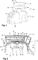
- the figure 1 which shows an assembly 10 comprising a device for grinding biological samples 12 and a cooling device 14 arranged above the device 12 for grinding samples.
- the assembly 10 includes a panel 16 for controlling the sample grinding device 12 and the cold generating device 14.
- the cold production device 14 comprises a first enclosure 18 arranged above the second enclosure 20 belonging to the sample grinding device 12. As can be seen in the figures. figures 1 and 2 , the first enclosure 18 or upper enclosure is carried so removable by a second enclosure 20 or lower enclosure ( figure 6 ). The first enclosure 18 can be locked in the mounting position on the second enclosure 20 by means of locking members 22 ( figure 7 ).
- the first enclosure 18 comprises a lateral annular wall 24 extending in a vertical direction A and a bottom wall 26 connected to the lower edge of the lateral annular wall 24 and of substantially complementary shape to an upper wall 28 of the second enclosure 20. or lower enclosure.
- the bottom wall 26 or lower wall of the upper enclosure 18 comprises an outlet opening 30 establishing fluid communication between an internal chamber 32 of the upper enclosure 18 and an internal chamber 34 of the lower enclosure 20 via an inlet opening 36 of the upper wall 28 of the lower enclosure 20.
- the upper wall 28 of the lower enclosure 20 is connected on its periphery to a lateral annular wall 38 extending substantially in the vertical direction A
- the lower wall 26 or the bottom wall of the upper enclosure 18 is applied to an adapter piece 39 making it possible to achieve a form coupling between the first enclosure 18 and the second enclosure 20.
- This adapter piece 39 allows the connection to be made. of the upper enclosure 18 on the lower enclosure 20 by means of the locking members 22.
- This part 39 may comprise a central tubular part 40 which is engaged in the opening 36 of the lower enclosure 20 and which receives a tightening nut 42. Note that this nut 42 makes it possible to tighten together the upper wall 28, an upper wall 41 internally delimiting the chamber 34 and the wall 39.
- the second enclosure 20 is double-walled.
- the internal chamber 34 of the lower enclosure 20 comprises means 44 for measuring the temperature in the chamber 34, which means 44 for measuring the temperature may be a sensor of the digital type and are carried by a face internal of a wall of the enclosure 20 internally delimiting the chamber 34 and are arranged near the opening 36 of the enclosure lower 20.
- the means 44 for measuring the temperature are connected to means 46 for controlling a flow rate of supply air to the chamber 32 of the upper enclosure 18.
- the lower enclosure 20 is formed by a removable cover and a part 47 of the frame.
- the removable cover can be pivotally mounted on the faired lower frame 48 of the assembly 10 ( figure 1 ).
- the lower enclosure 20 delimits an internal chamber 34 in which is arranged a plate 50 carrying sample tubes 52 at its periphery and mounted at the end of a shaft 54 driven in oscillating movement around a center of rotation located on the axis of the shaft 54.
- An electric motor is housed inside the faired frame 48 and allows the oscillation drive of the plate 50 and therefore of the tubes 52.
- the lower edge of the side wall 38 of the second enclosure 20 or lower enclosure rests on the frame 47 and thus covers the plate 50 and the tubes 52 for grinding the samples contained in the tubes 52.
- the first enclosure 18 or upper enclosure comprises a cover 56 pivoting about a substantially horizontal axis.
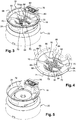
- the outer annular wall 24, the bottom wall 26 and the cover 56 together define the internal chamber 32 in which is removably mounted a cup 58 intended to receive a material 57 capable of producing cold by sublimation under normal temperature conditions. and pressure.
- the material 57 capable of sublimating is preferably CO 2 in the solid or dry ice form which has the advantage of being easily handled in the laboratory.
- the cup 58 comprises a frustoconical annular wall 60, the internal annular edge of which is connected to a rounded wall 62 comprising a concave internal face and a convex external face.
- the convexity of the curved or rounded wall 62 is turned outwards, that is to say towards the internal chamber 34 of the second enclosure.
- the rounded wall 62 or lower wall comprises a plurality of orifices 64.
- the outer annular edge of the frustoconical annular wall 60 is connected to a side annular wall 66 carrying an annular flange 68 intended to bear on the upper end of the side wall 24.
- the annular flange 68 comprises holes for the passage of screws for fixing the flange on the end. upper side wall 24 of the first enclosure 18.
- the collar 68 also includes lugs 71 distributed over its circumference, in this case three in number. These lugs 71 allow clipping of the retaining member carried by the cover 56.
- Curved or curved fins 70 are formed inside the cup 58 and extend from the curved wall 62 to the side annular wall 66 of the cup 58. These fins 70 provide retention of the material 57 capable of settling. sublimate substantially uniformly distributed in the cup 58 during handling thereof.
- the cup 58 is carried by structural elements 72 formed projecting from the bottom wall 26 of the first enclosure 18 ( figure 5 ).
- Thermal insulation means are preferably arranged between the cup 58 and the bottom wall 26 of the first enclosure 18 around the opening 30 of the first enclosure 18 and between the cup 58 and the side wall 24, in the housings. spacers 74 in order to limit heat loss by conduction of cold to the outside.
- the device In order to establish an air circulation from the outside into the internal chamber 32 of the first enclosure 18 upper enclosure, the device according to the invention comprises an air circuit as well as blowing means 76 making it possible to establish the desired air flow direction ( figures, 2 , 3 , 5 and 7 ).
- the air circuit for supplying air to the internal chamber 32 of the first enclosure 18 is made in two parts, an upstream part formed by a duct 78 integral with the lower enclosure 20 and more particularly with the upper wall 28 of the lower enclosure 20 and a downstream part formed by the cover 56.
- the upstream duct 78 houses the blowing means 76 in the vicinity of its upstream end opening into the outside air.
- the air blowing means 76 are thus carried by the lower enclosure 20 and that their electrical supply can thus be carried out by means of the electrical supply means of the device 12 for grinding samples.
- the upper enclosure 18, which is optional to the operation of the grinding device 12 can be designed without an electrical connection member or element, which greatly simplifies its manufacture.
- the duct 78 of the lower enclosure 20 is formed around the periphery of the upper wall 28 of the enclosure 20 and has a shape substantially complementary to that of a recess of the lateral annular wall 24 of the upper enclosure 18.
- the downstream end of duct 78 is engaged in an opening in cover 56 in order to establish air communication between the outside air and a cavity in cover 56 ( figures 8 and 9 ).
- This cavity of the cover 56 is delimited between an outer wall 80 and an inner wall 82, the inner wall comprising a first central passage 84 which is circular and second passages 86 of oblong shape, the largest dimension of which extends substantially radially with respect to at the first passage 84.
- a third passage 88 is formed between the opening or recess of the internal wall 82 of the cover 56 and the first passage 84.
- the cover 56 may have a substantially circular shape.
- Air circulation takes place as follows.
- the blowing means 76 impel a direction of air circulation in the upstream duct 78 as far as the cavity of the cover 56.
- the air then passes through the passages of the internal wall of the cover 56, the air then circulating in contact with the material.
- 57 capable of sublimating housed in the cup 58 which is mounted in the chamber of the upper enclosure.
- the material 57 sublimates more or less depending on the air flow entering the internal chamber 32.
- the cold air resulting from the sublimation of the material 57 then circulates through the orifices 64 of the cup 58. in the opening 30 of the upper enclosure 18 and in the opening 36 of the second enclosure 20 up to the chamber 34 in order to cool the tubes there when the latter are subjected to a crushing action of the samples housed in the tubes 52.
- the blowing means 76 are controlled by control means 46 making it possible to control the flow of outside air impelled into the air circuit by depending on the temperature in the chamber 34 of the lower enclosure 18.
- the fan can be controlled with a PWM type control which designates the acronym for “pulse width modulation” for pulse width modulation.
- the supply of air into the chamber 34 of the upper enclosure 20 does not induce any appreciable overpressure in this chamber 34 because the increase in pressure generated by the blowing means is low and that there is air outlet orifices to the outside, the dimensions of which are sufficient to evacuate the air to the outside air and to maintain the total pressure in the chamber 34 at the outside pressure.
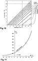
- the pressure in the chamber 34 is always equal to the external pressure, that is to say the atmospheric pressure, 1013 mbar to l inside the chamber, which makes it possible to reduce the dew point temperature during the addition of CO2 by sublimation of the dry ice.
- the vapor pressure will drop sharply, for example to 1 mbar, resulting in a very low saturation pressure, for example 200 Pa for a laboratory environment with a relative humidity of 50% and a negative dew point.
- the invention is particularly advantageous in a configuration in which the first enclosure is arranged above the second enclosure, in order to have good compactness of the device and a flow of cold air from the top to the bottom, it is understood that the invention can operate with a first enclosure and a second enclosure arranged relatively to each other in space in a different manner and for example side by side.
- the invention also covers embodiments in which the outlet opening 30 and the inlet opening 36 are connected to each other by a flexible or rigid conduit, generally by any means making it possible to establish a flow of cold air between the chamber 32 of the first enclosure 18 and the chamber 34 of the second enclosure 20.
Landscapes
- Engineering & Computer Science (AREA)
- Chemical & Material Sciences (AREA)
- Physics & Mathematics (AREA)
- General Health & Medical Sciences (AREA)
- Immunology (AREA)
- Health & Medical Sciences (AREA)
- Analytical Chemistry (AREA)
- Biochemistry (AREA)
- Pathology (AREA)
- General Physics & Mathematics (AREA)
- Life Sciences & Earth Sciences (AREA)
- Combustion & Propulsion (AREA)
- Mechanical Engineering (AREA)
- Thermal Sciences (AREA)
- General Engineering & Computer Science (AREA)
- Chemical Kinetics & Catalysis (AREA)
- Food Science & Technology (AREA)
- Sampling And Sample Adjustment (AREA)
Claims (13)
- Vorrichtung, insbesondere für ein Gerät zum Zerkleinern von biologischen Proben, umfassend eine erste Umwandung (18), die eine Innenkammer (32) umfasst, die dazu bestimmt ist, ein Material (57) aufzunehmen, das geeignet ist, Kälte durch Sublimation unter normalen Temperatur- und Druckbedingungen zu erzeugen, und die eine Öffnung (30) umfasst, die eine Fluidkommunikation mit einer Innenkammer einer zweiten Umwandung (20) durch eine Öffnung (36) der zweiten Umwandung (20) ermöglicht, wobei die Vorrichtung weiter einen Luftkreislauf umfasst, der die Außenluft mit der Innenkammer (32) der ersten Umwandung (18) kommunizieren lässt, Gebläsemittel (76), die eine Luftzirkulation in dem Luftkreislauf von außerhalb bis in die Innenkammer (32) der ersten Umwandung (18) ermöglichen, sowie Mittel (44) zum Messen der Temperatur in der Kammer der zweiten Umwandung (20) und Mittel zum Steuern (46) der Luftgebläsemittel (76) in Abhängigkeit von der Temperatur in der Kammer der zweiten Umwandung (20), und wobei eine Schale (58) zur Aufnahme des Materials (57) festsitzend oder abnehmbar im Inneren der Innenkammer (32) der ersten Umwandung (18) angebracht ist und eine untere Wand (26) umfasst, die eine Vielzahl von Löchern (64) umfasst, wobei die Schale (58) entfernt von einer Bodenwand (26) der ersten Umwandung (18) positioniert ist, in der die Öffnung (30) der ersten Umwandung (18) gebildet ist.
- Vorrichtung nach Anspruch 1, wobei der Luftkreislauf Luftgebläsemittel (76) beherbergt und einen Ausgang umfasst, der in einen oberen Teil der ersten Umwandung (18) mündet.
- Vorrichtung nach Anspruch 1 oder 2, wobei der Luftkreislauf einen stromaufwärtigen Kanal (78) umfasst, von dem ein stromaufwärtiges Ende in die Außenluft mündet.
- Vorrichtung nach Anspruch 3, wobei ein stromabwärtiges Ende des stromaufwärtigen Kanals (78) in einen Hohlraum eines doppelwandigen Deckels (56) mündet, von dem eine Innenwand (82) ein Vielzahl von Durchlässen (84, 86, 88) umfasst, die in die Innenkammer (32) der ersten Umwandung (18) münden.
- Vorrichtung nach Anspruch 3 oder 4, wobei der stromaufwärtige Kanal (78) die Luftgebläsemittel (76) beherbergt und fest mit der zweiten Umwandung (20) verbunden ist, wobei die Luftgebläsemittel (76) mit Stromversorgungsmitteln verbunden sind, die ebenfalls von der zweiten Umwandung (20) getragen werden.
- Vorrichtung nach einem der vorstehenden Ansprüche, wobei die Luftgebläsemittel (76) einen Lüfter umfassen, der am Eingang des Luftkreislaufes angeordnet ist.
- Vorrichtung nach einem der vorstehenden Ansprüche, wobei Wärmeisolationsmittel zwischen der Schale (58) und der Bodenwand (26) der ersten Umwandung (18) rund um die Öffnung (30) der ersten Umwandung (18) angeordnet sind.
- Vorrichtung nach einem der Ansprüche 1 bis 7, wobei die erste Umwandung (18) über der zweiten Umwandung (20) angeordnet ist und die Öffnung der ersten Umwandung (18) in der Bodenwand (26) der ersten Umwandung (18) gebildet ist und wobei die Öffnung (36) der zweiten Umwandung (20) in einer oberen Wand (28) der zweiten Umwandung (20) gebildet ist.
- Vorrichtung nach Anspruch 8, wobei die erste Umwandung (18) abnehmbar auf der zweiten Umwandung (20) angebracht ist.
- Vorrichtung nach einem der vorstehenden Ansprüche, wobei die Mittel (44) zum Messen der Temperatur einen Temperaturfühler umfassen, der von einer Innenfläche der zweiten Umwandung (20) und in der Nähe der Öffnung (36) der zweiten Umwandung (20) getragen wird.
- Vorrichtung nach einem der vorstehenden Ansprüche, wobei eine Platte (50) zum Tragen von Röhren (52), die dazu bestimmt sind, biologische Proben zu enthalten, im Inneren der Kammer der zweiten Umwandung (20) angeordnet ist, wobei Mittel zum Antreiben der Platte (50) in eine Schwingbewegung rund um einen Drehpunkt ebenfalls vorgesehen sind.
- Vorrichtung nach einem der vorstehenden Ansprüche, wobei sich die Kammer (34) der zweiten Umwandung (20) in Fluidverbindung mit der Außenluft befindet.
- Verfahren zur Anwendung der Vorrichtung nach einem der vorstehenden Ansprüche, umfassend folgende Schritte:- Füllen der Innenkammer (32) der ersten Umwandung (18) mit einem Material (57), das geeignet ist, Kälte durch Sublimation unter normalen Temperatur- und Druckbedingungen zu erzeugen, wie etwa Kohlendioxid in fester Form, wobei der Schritt des Füllens der Innenkammer (32) das Anbringen einer Schale (58) zur Aufnahme des Materials (57) im Inneren der Innenkammer (32) der ersten Umwandung (18) umfasst, wobei die Schale eine untere Wand (26) umfasst, die eine Vielzahl von Löchern (64) umfasst, und entfernt von einer Bodenwand (26) der ersten Umwandung (18) positioniert ist, in der die Öffnung (30) der ersten Umwandung (18) gebildet ist;- Bestimmen einer zu erreichenden Solltemperatur für die Kammer (34) der zweiten Umwandung (20),- Inbetriebsetzen der Vorrichtung, sodass die Temperatur der Kammer (34) der zweiten Umwandung (20) auf der Solltemperatur gehalten wird, indem der Luftdurchsatz, mit dem die Kammer (32) der ersten Umwandung (18) versorgt wird, gesteuert wird.
Applications Claiming Priority (2)
| Application Number | Priority Date | Filing Date | Title |
|---|---|---|---|
| FR1752810A FR3064729B1 (fr) | 2017-03-31 | 2017-03-31 | Dispositif de refroidissement |
| PCT/FR2018/050813 WO2018178602A1 (fr) | 2017-03-31 | 2018-03-30 | Dispositif de refroidissement |
Publications (2)
| Publication Number | Publication Date |
|---|---|
| EP3601909A1 EP3601909A1 (de) | 2020-02-05 |
| EP3601909B1 true EP3601909B1 (de) | 2021-04-21 |
Family
ID=59031159
Family Applications (1)
| Application Number | Title | Priority Date | Filing Date |
|---|---|---|---|
| EP18722674.1A Active EP3601909B1 (de) | 2017-03-31 | 2018-03-30 | Kühlgerät |
Country Status (5)
| Country | Link |
|---|---|
| US (1) | US11959843B2 (de) |
| EP (1) | EP3601909B1 (de) |
| CN (1) | CN110892214B (de) |
| FR (1) | FR3064729B1 (de) |
| WO (1) | WO2018178602A1 (de) |
Families Citing this family (2)
| Publication number | Priority date | Publication date | Assignee | Title |
|---|---|---|---|---|
| DE102019120550B4 (de) * | 2019-07-30 | 2023-07-20 | Awas Fee Gmbh | Verfahren zum explosionsgeschützten Auftauen von schüttguttransportierenden Transportmitteln |
| US12090481B2 (en) * | 2020-11-03 | 2024-09-17 | Applied Cells Inc. | Microfluidic system including cooling device |
Family Cites Families (6)
| Publication number | Priority date | Publication date | Assignee | Title |
|---|---|---|---|---|
| US7266965B2 (en) * | 2000-06-21 | 2007-09-11 | Blackstone Ralf W | Air cooling device |
| FR2903026B1 (fr) | 2006-06-30 | 2008-12-26 | Bertin Technologies Soc Par Ac | Appareil de broyage d'echantillons biologiques |
| JP2011007472A (ja) * | 2009-06-29 | 2011-01-13 | Nippon Buroaa Kk | 保冷輸送用コンテナ及びその制御方法 |
| US9303912B1 (en) * | 2010-05-11 | 2016-04-05 | The Boeing Company | Passively cooled container system and method |
| US9340839B2 (en) * | 2013-04-04 | 2016-05-17 | Forward Biotech, Inc. | Integrated temperature control of laboratory instrument |
| US20150375932A1 (en) * | 2014-06-25 | 2015-12-31 | David King ANDERSON, III | Temperature Controlled Container For Storing And Transporting Core Samples |
-
2017
- 2017-03-31 FR FR1752810A patent/FR3064729B1/fr active Active
-
2018
- 2018-03-30 EP EP18722674.1A patent/EP3601909B1/de active Active
- 2018-03-30 WO PCT/FR2018/050813 patent/WO2018178602A1/fr not_active Ceased
- 2018-03-30 US US16/499,109 patent/US11959843B2/en active Active
- 2018-03-30 CN CN201880030840.9A patent/CN110892214B/zh active Active
Also Published As
| Publication number | Publication date |
|---|---|
| CN110892214B (zh) | 2022-04-01 |
| US11959843B2 (en) | 2024-04-16 |
| CN110892214A (zh) | 2020-03-17 |
| EP3601909A1 (de) | 2020-02-05 |
| FR3064729A1 (fr) | 2018-10-05 |
| US20210310914A1 (en) | 2021-10-07 |
| WO2018178602A1 (fr) | 2018-10-04 |
| FR3064729B1 (fr) | 2021-01-01 |
Similar Documents
| Publication | Publication Date | Title |
|---|---|---|
| CA2655711C (fr) | Appareil de broyage d'echantillons biologiques | |
| EP0628723B1 (de) | Selbstkühlende integrierte Pumpe für kryogene Flüssigkeit | |
| EP2180583B1 (de) | Gerät mit Rührbottich | |
| EP3601909B1 (de) | Kühlgerät | |
| FR2971093A1 (fr) | Batterie thermiquement regulee ou refroidie et vehicule equipe d'une telle batterie | |
| EP3194075A1 (de) | Einheit zum schleifen von biologischen proben | |
| WO2006061517A1 (fr) | Dispositif de depot sous vide a reservoir de recharge et procédé de dépôt sous vide correspondant | |
| EP2103565B1 (de) | Getränkeautomat, der mit einem Kühlmittel- oder Wärmeübertragungselement ausgestattet ist | |
| EP2387921B1 (de) | Gerät zum Erwärmen von Lebensmitteln mit zwei übereinanderliegenden Kammern und Entlüftung. | |
| CA2898870C (fr) | Cellule de trempe sous gaz | |
| EP1740898B1 (de) | Entwässerungsinstallation unter verwendung von zeolithen | |
| FR3105316A1 (fr) | Support d’un groupe moto-ventilateur pour un véhicule automobile | |
| EP3610942B1 (de) | Antikontaminationsflansch für parylen-maschine | |
| EP1790922B1 (de) | Kühlgerät mit Eiswürfelbehälter | |
| FR2928665A1 (fr) | Four industriel pour la fabrication d'un lingot de materiau cristallin | |
| EP2647931A1 (de) | Speichervorrichtung für Produkte bei kryogenen Temperaturen | |
| FR2893706A1 (fr) | Bac a glacons, notamment pour appareil electromenager du type refrigerateur | |
| FR2916524A1 (fr) | Dispositif de regulation de la circulation d'un fluide dans un echangeur de chaleur,et module d'admission d'air associe | |
| EP1373604A1 (de) | Behälter für eine epitaxie-anlage und anlage mit solchem behälter | |
| BE819132A (fr) | Installation pour le transport de poissons vivants |
Legal Events
| Date | Code | Title | Description |
|---|---|---|---|
| STAA | Information on the status of an ep patent application or granted ep patent |
Free format text: STATUS: UNKNOWN |
|
| STAA | Information on the status of an ep patent application or granted ep patent |
Free format text: STATUS: THE INTERNATIONAL PUBLICATION HAS BEEN MADE |
|
| PUAI | Public reference made under article 153(3) epc to a published international application that has entered the european phase |
Free format text: ORIGINAL CODE: 0009012 |
|
| STAA | Information on the status of an ep patent application or granted ep patent |
Free format text: STATUS: REQUEST FOR EXAMINATION WAS MADE |
|
| 17P | Request for examination filed |
Effective date: 20190926 |
|
| AK | Designated contracting states |
Kind code of ref document: A1 Designated state(s): AL AT BE BG CH CY CZ DE DK EE ES FI FR GB GR HR HU IE IS IT LI LT LU LV MC MK MT NL NO PL PT RO RS SE SI SK SM TR |
|
| AX | Request for extension of the european patent |
Extension state: BA ME |
|
| DAV | Request for validation of the european patent (deleted) | ||
| DAX | Request for extension of the european patent (deleted) | ||
| GRAP | Despatch of communication of intention to grant a patent |
Free format text: ORIGINAL CODE: EPIDOSNIGR1 |
|
| STAA | Information on the status of an ep patent application or granted ep patent |
Free format text: STATUS: GRANT OF PATENT IS INTENDED |
|
| INTG | Intention to grant announced |
Effective date: 20210125 |
|
| GRAS | Grant fee paid |
Free format text: ORIGINAL CODE: EPIDOSNIGR3 |
|
| GRAA | (expected) grant |
Free format text: ORIGINAL CODE: 0009210 |
|
| STAA | Information on the status of an ep patent application or granted ep patent |
Free format text: STATUS: THE PATENT HAS BEEN GRANTED |
|
| AK | Designated contracting states |
Kind code of ref document: B1 Designated state(s): AL AT BE BG CH CY CZ DE DK EE ES FI FR GB GR HR HU IE IS IT LI LT LU LV MC MK MT NL NO PL PT RO RS SE SI SK SM TR |
|
| REG | Reference to a national code |
Ref country code: GB Ref legal event code: FG4D Free format text: NOT ENGLISH |
|
| REG | Reference to a national code |
Ref country code: CH Ref legal event code: EP |
|
| REG | Reference to a national code |
Ref country code: DE Ref legal event code: R096 Ref document number: 602018015885 Country of ref document: DE Ref country code: IE Ref legal event code: FG4D Free format text: LANGUAGE OF EP DOCUMENT: FRENCH |
|
| REG | Reference to a national code |
Ref country code: AT Ref legal event code: REF Ref document number: 1385060 Country of ref document: AT Kind code of ref document: T Effective date: 20210515 |
|
| REG | Reference to a national code |
Ref country code: NL Ref legal event code: FP |
|
| REG | Reference to a national code |
Ref country code: LT Ref legal event code: MG9D |
|
| REG | Reference to a national code |
Ref country code: AT Ref legal event code: MK05 Ref document number: 1385060 Country of ref document: AT Kind code of ref document: T Effective date: 20210421 |
|
| PG25 | Lapsed in a contracting state [announced via postgrant information from national office to epo] |
Ref country code: BG Free format text: LAPSE BECAUSE OF FAILURE TO SUBMIT A TRANSLATION OF THE DESCRIPTION OR TO PAY THE FEE WITHIN THE PRESCRIBED TIME-LIMIT Effective date: 20210721 Ref country code: AT Free format text: LAPSE BECAUSE OF FAILURE TO SUBMIT A TRANSLATION OF THE DESCRIPTION OR TO PAY THE FEE WITHIN THE PRESCRIBED TIME-LIMIT Effective date: 20210421 Ref country code: LT Free format text: LAPSE BECAUSE OF FAILURE TO SUBMIT A TRANSLATION OF THE DESCRIPTION OR TO PAY THE FEE WITHIN THE PRESCRIBED TIME-LIMIT Effective date: 20210421 Ref country code: HR Free format text: LAPSE BECAUSE OF FAILURE TO SUBMIT A TRANSLATION OF THE DESCRIPTION OR TO PAY THE FEE WITHIN THE PRESCRIBED TIME-LIMIT Effective date: 20210421 Ref country code: FI Free format text: LAPSE BECAUSE OF FAILURE TO SUBMIT A TRANSLATION OF THE DESCRIPTION OR TO PAY THE FEE WITHIN THE PRESCRIBED TIME-LIMIT Effective date: 20210421 |
|
| PG25 | Lapsed in a contracting state [announced via postgrant information from national office to epo] |
Ref country code: IS Free format text: LAPSE BECAUSE OF FAILURE TO SUBMIT A TRANSLATION OF THE DESCRIPTION OR TO PAY THE FEE WITHIN THE PRESCRIBED TIME-LIMIT Effective date: 20210821 Ref country code: GR Free format text: LAPSE BECAUSE OF FAILURE TO SUBMIT A TRANSLATION OF THE DESCRIPTION OR TO PAY THE FEE WITHIN THE PRESCRIBED TIME-LIMIT Effective date: 20210722 Ref country code: NO Free format text: LAPSE BECAUSE OF FAILURE TO SUBMIT A TRANSLATION OF THE DESCRIPTION OR TO PAY THE FEE WITHIN THE PRESCRIBED TIME-LIMIT Effective date: 20210721 Ref country code: PL Free format text: LAPSE BECAUSE OF FAILURE TO SUBMIT A TRANSLATION OF THE DESCRIPTION OR TO PAY THE FEE WITHIN THE PRESCRIBED TIME-LIMIT Effective date: 20210421 Ref country code: LV Free format text: LAPSE BECAUSE OF FAILURE TO SUBMIT A TRANSLATION OF THE DESCRIPTION OR TO PAY THE FEE WITHIN THE PRESCRIBED TIME-LIMIT Effective date: 20210421 Ref country code: RS Free format text: LAPSE BECAUSE OF FAILURE TO SUBMIT A TRANSLATION OF THE DESCRIPTION OR TO PAY THE FEE WITHIN THE PRESCRIBED TIME-LIMIT Effective date: 20210421 Ref country code: SE Free format text: LAPSE BECAUSE OF FAILURE TO SUBMIT A TRANSLATION OF THE DESCRIPTION OR TO PAY THE FEE WITHIN THE PRESCRIBED TIME-LIMIT Effective date: 20210421 Ref country code: PT Free format text: LAPSE BECAUSE OF FAILURE TO SUBMIT A TRANSLATION OF THE DESCRIPTION OR TO PAY THE FEE WITHIN THE PRESCRIBED TIME-LIMIT Effective date: 20210823 |
|
| REG | Reference to a national code |
Ref country code: DE Ref legal event code: R097 Ref document number: 602018015885 Country of ref document: DE |
|
| PG25 | Lapsed in a contracting state [announced via postgrant information from national office to epo] |
Ref country code: SK Free format text: LAPSE BECAUSE OF FAILURE TO SUBMIT A TRANSLATION OF THE DESCRIPTION OR TO PAY THE FEE WITHIN THE PRESCRIBED TIME-LIMIT Effective date: 20210421 Ref country code: ES Free format text: LAPSE BECAUSE OF FAILURE TO SUBMIT A TRANSLATION OF THE DESCRIPTION OR TO PAY THE FEE WITHIN THE PRESCRIBED TIME-LIMIT Effective date: 20210421 Ref country code: EE Free format text: LAPSE BECAUSE OF FAILURE TO SUBMIT A TRANSLATION OF THE DESCRIPTION OR TO PAY THE FEE WITHIN THE PRESCRIBED TIME-LIMIT Effective date: 20210421 Ref country code: RO Free format text: LAPSE BECAUSE OF FAILURE TO SUBMIT A TRANSLATION OF THE DESCRIPTION OR TO PAY THE FEE WITHIN THE PRESCRIBED TIME-LIMIT Effective date: 20210421 Ref country code: SM Free format text: LAPSE BECAUSE OF FAILURE TO SUBMIT A TRANSLATION OF THE DESCRIPTION OR TO PAY THE FEE WITHIN THE PRESCRIBED TIME-LIMIT Effective date: 20210421 Ref country code: CZ Free format text: LAPSE BECAUSE OF FAILURE TO SUBMIT A TRANSLATION OF THE DESCRIPTION OR TO PAY THE FEE WITHIN THE PRESCRIBED TIME-LIMIT Effective date: 20210421 Ref country code: DK Free format text: LAPSE BECAUSE OF FAILURE TO SUBMIT A TRANSLATION OF THE DESCRIPTION OR TO PAY THE FEE WITHIN THE PRESCRIBED TIME-LIMIT Effective date: 20210421 |
|
| PLBE | No opposition filed within time limit |
Free format text: ORIGINAL CODE: 0009261 |
|
| STAA | Information on the status of an ep patent application or granted ep patent |
Free format text: STATUS: NO OPPOSITION FILED WITHIN TIME LIMIT |
|
| 26N | No opposition filed |
Effective date: 20220124 |
|
| PG25 | Lapsed in a contracting state [announced via postgrant information from national office to epo] |
Ref country code: IS Free format text: LAPSE BECAUSE OF FAILURE TO SUBMIT A TRANSLATION OF THE DESCRIPTION OR TO PAY THE FEE WITHIN THE PRESCRIBED TIME-LIMIT Effective date: 20210821 Ref country code: AL Free format text: LAPSE BECAUSE OF FAILURE TO SUBMIT A TRANSLATION OF THE DESCRIPTION OR TO PAY THE FEE WITHIN THE PRESCRIBED TIME-LIMIT Effective date: 20210421 |
|
| PG25 | Lapsed in a contracting state [announced via postgrant information from national office to epo] |
Ref country code: MC Free format text: LAPSE BECAUSE OF FAILURE TO SUBMIT A TRANSLATION OF THE DESCRIPTION OR TO PAY THE FEE WITHIN THE PRESCRIBED TIME-LIMIT Effective date: 20210421 |
|
| REG | Reference to a national code |
Ref country code: CH Ref legal event code: PL |
|
| PG25 | Lapsed in a contracting state [announced via postgrant information from national office to epo] |
Ref country code: LU Free format text: LAPSE BECAUSE OF NON-PAYMENT OF DUE FEES Effective date: 20220330 Ref country code: LI Free format text: LAPSE BECAUSE OF NON-PAYMENT OF DUE FEES Effective date: 20220331 Ref country code: IE Free format text: LAPSE BECAUSE OF NON-PAYMENT OF DUE FEES Effective date: 20220330 Ref country code: CH Free format text: LAPSE BECAUSE OF NON-PAYMENT OF DUE FEES Effective date: 20220331 |
|
| P01 | Opt-out of the competence of the unified patent court (upc) registered |
Effective date: 20230517 |
|
| PG25 | Lapsed in a contracting state [announced via postgrant information from national office to epo] |
Ref country code: MK Free format text: LAPSE BECAUSE OF FAILURE TO SUBMIT A TRANSLATION OF THE DESCRIPTION OR TO PAY THE FEE WITHIN THE PRESCRIBED TIME-LIMIT Effective date: 20210421 Ref country code: CY Free format text: LAPSE BECAUSE OF FAILURE TO SUBMIT A TRANSLATION OF THE DESCRIPTION OR TO PAY THE FEE WITHIN THE PRESCRIBED TIME-LIMIT Effective date: 20210421 |
|
| PG25 | Lapsed in a contracting state [announced via postgrant information from national office to epo] |
Ref country code: HU Free format text: LAPSE BECAUSE OF FAILURE TO SUBMIT A TRANSLATION OF THE DESCRIPTION OR TO PAY THE FEE WITHIN THE PRESCRIBED TIME-LIMIT; INVALID AB INITIO Effective date: 20180330 |
|
| PG25 | Lapsed in a contracting state [announced via postgrant information from national office to epo] |
Ref country code: MT Free format text: LAPSE BECAUSE OF FAILURE TO SUBMIT A TRANSLATION OF THE DESCRIPTION OR TO PAY THE FEE WITHIN THE PRESCRIBED TIME-LIMIT Effective date: 20210421 |
|
| PGFP | Annual fee paid to national office [announced via postgrant information from national office to epo] |
Ref country code: NL Payment date: 20260226 Year of fee payment: 9 |
|
| PGFP | Annual fee paid to national office [announced via postgrant information from national office to epo] |
Ref country code: GB Payment date: 20260323 Year of fee payment: 9 |
|
| PGFP | Annual fee paid to national office [announced via postgrant information from national office to epo] |
Ref country code: DE Payment date: 20260313 Year of fee payment: 9 |
|
| PGFP | Annual fee paid to national office [announced via postgrant information from national office to epo] |
Ref country code: BE Payment date: 20260324 Year of fee payment: 9 Ref country code: IT Payment date: 20260309 Year of fee payment: 9 |
|
| PGFP | Annual fee paid to national office [announced via postgrant information from national office to epo] |
Ref country code: FR Payment date: 20260326 Year of fee payment: 9 |
|
| PGFP | Annual fee paid to national office [announced via postgrant information from national office to epo] |
Ref country code: TR Payment date: 20260313 Year of fee payment: 9 |